1
802.11b/g/n
Wireless Broadband
Router
User’s Manual
Table of Contents
CHAPTER 1: INTRODUCTION ............................................................................................ 3
FEATURES ................................................................................................................................ 3
PACKAGE CONTENTS ............................................................................................................... 3
PHYSICAL DETAILS .................................................................................................................. 4
ABOUT THE OPERATION MODES .............................................................................................. 6
CHAPTER 2: INSTALLATION ............................................................................................. 8
REQUIREMENTS ........................................................................................................................ 8
PROCEDURE ............................................................................................................................. 8
CHAPTER 3: CONFIGURATION VIA WEB..................................................................... 10
OVERVIEW ............................................................................................................................. 10
CONFIGURATION PROGRAM ................................................................................................... 10
SETUP WIZARD ...................................................................................................................... 12
OPERATION MODE ................................................................................................................. 17
WIRELESS .............................................................................................................................. 18
TCP/IP SETTINGS................................................................................................................... 29
FIREWALL .............................................................................................................................. 33
QOS ....................................................................................................................................... 39
MANAGEMENT ....................................................................................................................... 40
LOGOUT ................................................................................................................................. 46
CHAPTER 4: PC CONFIGURATION................................................................................. 47
OVERVIEW ............................................................................................................................. 47
WINDOWS CLIENTS ................................................................................................................ 47
MACINTOSH CLIENTS ............................................................................................................. 52
LINUX CLIENTS ...................................................................................................................... 52
OTHER UNIX SYSTEMS ........................................................................................................... 52
WIRELESS STATION CONFIGURATION .................................................................................... 53
APPENDIX A: TROUBLESHOOTING.............................................................................. 54
OVERVIEW ............................................................................................................................. 54
GENERAL PROBLEMS ............................................................................................................. 54
INTERNET ACCESS.................................................................................................................. 55
WIRELESS ACCESS ................................................................................................................. 56
APPENDIX B: ABOUT WIRELESS LANS........................................................................ 57
MODES ................................................................................................................................... 57
BSS........................................................................................................................................ 57
CHANNELS ............................................................................................................................. 57
SECURITY ............................................................................................................................... 58
WIRELESS LAN CONFIGURATION .......................................................................................... 59
APPENDIX C: SPECIFICATIONS ..................................................................................... 60
802.11N/B/G WIRELESS BROADBAND ROUTER ...................................................................... 60
Federal Communication Commission
Interference Statement
This equipment has been tested and found to comply with the limits for a Class B
digital device, pursuant to Part 15 of the FCC Rules. These limits are designed to
provide reasonable protection against harmful interference in a residential installation.
This equipment generates uses and can radiate radio frequency energy and, if not
installed and used in accordance with the instructions, may cause harmful interference to radio communications. However, there is no guarantee that interference will
not occur in a particular installation. If this equipment does cause harmful interference
to radio or television reception, which can be determined by turning the equipment off
and on, the user is encouraged to try to correct the interference by one of the following
measures:
- Reorient or relocate the receiving antenna.
- Increase the separation between the equipment and receiver.
- Connect the equipment into an outlet on a circuit different from that to which the
receiver is connected.
- Consult the dealer or an experienced radio/TV technician for help.
This device complies with Part 15 of the FCC Rules. Operation is subject to the following two conditions: (1) This device may not cause harmful interference, and (2) this
device must accept any interference received, including interference that may cause
undesired operation.
FCC Caution: Any changes or modifications not expressly approved by the party
responsible for compliance could void the user's authority to operate this equipment.
IEEE 802.11b or 802.11g operation of this product in the U.S.A. is firmware-limited to
channels 1 through 11.
IMPORTANT NOTE:
FCC Radiation Exposure Statement:
This equipment complies with FCC radiation exposure limits set forth for an uncontrolled environment. This equipment should be installed and operated with minimum
distance 20cm between the radiator & your body.
This transmitter must not be co-located or operating in conjunction with any other
antenna or transmitter.
The availability of some specific channels and/or operational frequency bands are
country dependent and are firmware programmed at the factory to match the intended
destination. The firmware setting is not accessible by the end user.
2
Chapter 1: Introduction
The 802.11b/g/n Wireless Broadband Router is a draft 802.11n/b/g compliant Wireless
Broadband Router with 4-port Fast Ethernet Switch. With the advanced MIMO technology, it
can support the data transmission rate 6 times more (up to 300Mbps) and the coverage 3 times
more than IEEE 802.11b/g devices. 802.11b/g/n Wireless Broadband Router enables your
whole network sharing a high-speed cable or DSL Internet connection. The incredible speed of
802.11b/g/n Wireless Broadband Router makes it ideal for media-centric applications like
streaming video, gaming, and Voice over IP technology, ensure optimum performance and
maximum coverage with two external antennas.
With 802.11b/g/n Wireless Broadband Router, you can share a high-speed Internet connection, files, printers, and multi-player games at incredible speeds, without the hassle of stringing
wires. 802.11b/g/n Wireless Broadband Router offers easy configuration for your wireless
network in the home and presents wireless network to you home of high functionality, security,
and flexibility.
Features
•
Support the IEEE 802.11b/g/n standard, high speed date rate up to 300Mbps.
•
Support WPS (Wi-Fi Protected Setup) with physical reset button.
•
High security with built-in Security: WEP 64/128 bits, WPA, WPA2, 802.1x and
802.11i.
•
Support Router, AP, WDS (Bridge + Repeater) and Client.
•
Advanced Quality of Service (QoS) - 802.11e, WMM.
•
Easy configuration for home user setup.
Package Contents
The following items should be included:
•
The Wireless Router Unit
•
Power Adapter
•
Quick Installation Guide
•
CD-ROM containing the on-line manual
If any of the above items are damaged or missing, please contact your dealer immediately.
3
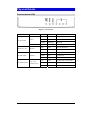
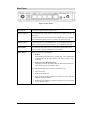
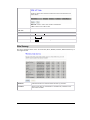
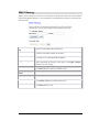
Physical Details
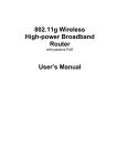
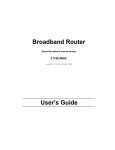
Front-mounted LEDs
Figure 1: Front Panel
LED
Printed
Power
Power/ WPS
WPS
Wireless LAN
10/100 WAN
10/100M Switch
WLAN
Internet
n (n=1~4)
LAN/Activity
Color
Behavior
Indication
N/A
Off
No power
Green
On
System powered on
Orange
Blinking
Booting
Green
Blinking
WPS link (Duration 2 min)
N/A
Off
WLAN Disabled
Green
Blinking
WLAN Enabled
N/A
Off
Link failed, or not linked
Green
On
Link active
Green
Blinking
Traffic transmitting
N/A
Off
Link failed, or not linked
Green
On
Link active
Green
Blinking
Traffic transmitting
4
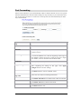
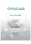
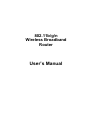
Rear Panel
Figure 2: Rear Panel
Power port
Connect the supplied power adapter here.
LAN 1~4 ports
Use standard LAN cables (RJ45 connectors) to connect your PCs to
these ports.
If required, any port can be connected to another hub. Any LAN port
will automatically function as an "Uplink" port when necessary.
Internet port
Connect the DSL or Cable Modem here. If your modem came with a
cable, use the supplied cable. Otherwise, use a standard LAN cable.
WPS Button
To enable the WPS function, keep pressing the Reset Button more
than 2 seconds, until the GREEN LED has flashed.
Reset Button
This button has two (2) functions:
• Reboot
When holding the button for 2 seconds, the power LED blinks
in ORANGE, the Wireless Router will reboot (restart) automatically.
• Restore Factory Default Setting
This button can also be used to clear all data and restore all settings back to the factory default values.
To Clear All Data and restore the factory default values:
1. After Power On.
2. Press the Reset Button.
3. Keep pressing the Reset Button more than 5 seconds, until the
GREEN LED has flashed.
4. Release the Reset Button. The Wireless Router is now using the
factory default values.
5
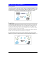
About the Operation Modes
Gateway Mode
In this mode, the device is supposed to connect to internet via ADSL/Cable Modem. The NAT
is enabled and PCs in LAN ports share the same IP to ISP through WAN port. The connection
type can be setup in WAN page by using PPPOE, DHCP client, PPTP client or static IP.
Bridge Mode
The WDS (Wireless Distributed System) function lets this access point act as a wireless LAN
access point and repeater at the same time. Users can use this feature to build up a large wireless network in a large space like airports, hotels and schools and so on. This feature is also
useful when users want to bridge networks between buildings where it is impossible to deploy
network cable connections between these buildings.
In this mode, all Ethernet ports and wireless interface are bridge together and NAT function is
disabled. All the WAN related function and firewall are not supported.
Wireless Distribution System uses wireless media to communicate with other APs, like the
Ethernet does. To do this, you must set these APs in the same channel and set MAC address of
other APs which you want to communicate with in the table and then enable the WDS.
6
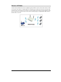
Wireless ISP Mode
In this mode, all Ethernet ports are bridged together and the wireless client will connect to ISP
access point. The NAT is enabled and PCs in Ethernet ports share the same IP to ISP through
wireless LAN. You must set the wireless to client mode first and connect to the ISP AP in SiteSurvey page. The connection type can be setup in WAN page by using PPPOE, DHCP client,
PPTP client or static IP.
7
Chapter 2: Installation
Requirements
•
Network cables. Use standard 10/100BaseT network (UTP) cables with RJ45 connectors.
•
TCP/IP protocol must be installed on all PCs.
•
For Internet Access, an Internet Access account with an ISP, and either of a DSL or Cable
modem (for WAN port usage.)
•
To use the Wireless Access Point, all wireless devices must be compliant with the
IEEE802.11b or IEEE802.11g specifications.
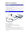
Procedure
1. Choose an Installation Site
Select a suitable place on the network to install the Wireless Router.
Ensure the Wireless Router and the DSL/Cable modem are powered OFF.
2. Connect LAN Cables
Use standard LAN cables to connect PCs to the switching hub ports on the Wireless
Router. Both 10BaseT and 100BaseT connections can be used simultaneously.
If required, connect any port to a normal port on another hub, using a standard LAN cable.
Any LAN port on the Wireless Router will automatically function as an "Uplink" port
when required.
3. Connect WAN Cable
Connect the DSL or Cable modem to the WAN port on the Wireless Router. Use the cable
supplied with your DSL/Cable modem. If no cable was supplied, use a standard cable.
4. Power Up
•
Power on the Cable or DSL modem.
•
Connect the supplied power adapter to the Wireless Router and power up.
Use only the power adapter provided. Using a different one may cause hardware damaged.
5. Check the LEDs
•
The Power LED should be ON.
•
For each LAN (PC) connection, the LAN Link/Act LED should be ON (provided the PC is
also ON.)
•
The WAN LED should be ON.
•
The WLAN LED should be ON.
For more information, refer to Front-mounted LEDs in Chapter 1.
9
Chapter 3: Configuration via Web
Overview
This chapter describes the setup procedure for:
•
Internet Access
•
LAN configuration
•
Wireless setup
•
Assigning a password to protect the configuration data
PCs on your local LAN may also require configuration. For details, see Chapter 4 - PC Configuration.
Other configuration may also be required, depending on which features and functions of the
Wireless Router you wish to use. Use the table below to locate detailed instructions for the
required functions.
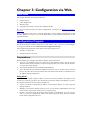
Configuration Program
The Wireless Router contains a HTTP server. This enables you to connect to it, and configure
it, using your Web Browser. Your Browser must support JavaScript.
The configuration program has been tested on the following browsers:
•
Netscape V4.08 or later
•
Internet Explorer V4 or later
Preparations
Before attempting to configure the Wireless Router, please ensure that:
•
Your PC can establish a physical connection to the Wireless Router. The PC and the
Wireless Router must be directly connected (using the Hub ports on the Wireless Router)
or on the same LAN segment.
•
The Wireless Router must be installed and powered ON.
•
If the Wireless Router's default IP Address (192.168.1.254) is already used by another
device, the other device must be turned OFF until the Wireless Router is allocated a new
IP Address during configuration.
Using UPnP
If your Windows system supports UPnP, an icon for the Wireless Router will appear in the
system tray, notifying you that a new network device has been found, and offering to create a
new desktop shortcut to the newly-discovered device.
•
Unless you intend to change the IP Address of the Wireless Router, you can accept the
desktop shortcut.
•
Whether you accept the desktop shortcut or not, you can always find UPnP devices in My
Network Places (previously called Network Neighborhood).
•
Double - click the icon for the Wireless Router (either on the Desktop, or in My Network
Places) to start the configuration. Refer to the following section Setup Wizard for details
of the initial configuration process.
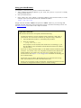
Using your Web Browser
To establish a connection from your PC to the Wireless Router:
1. After installing the Wireless Router in your LAN, start your PC. If your PC is already
running, please restart it.
2. Start your Web Browser.
3. In the Address box, enter "HTTP://" and the IP Address of the Wireless Router, as in this
example, which uses the Wireless Router's default IP Address:
HTTP://192.168.1.254
Simply enter the username "admin" and password “admin”. However, you can assign and
changed username and set the password for future security in the Password Setup section. See
the Password Setup section later in this chapter for details.
If you can't connect...
If the Wireless Router does not respond, check the following:
•
The Wireless Router is properly installed, LAN connection is OK, and it is
powered ON. You can test the connection by using the "Ping" command:
•
Open the MS-DOS window or command prompt window.
•
Enter the command:
ping 192.168.1.254
If no response is received, either the connection is not working, or your
PC's IP address is not compatible with the Wireless Router's IP Address.
(See next item.)
•
If your PC is using a fixed IP Address, its IP Address must be within the range
192.168.1.1 to 192.168.1.253 to be compatible with the Wireless Router's default IP Address of 192.168.1.254. Also, the Network Mask must be set to
255.255.255.0. See Chapter 4 - PC Configuration for details on checking your
PC's TCP/IP settings.
•
Ensure that your PC and the Wireless Router are on the same network segment. (If you don't have a router, this must be the case.)
•
Ensure you are using the wired LAN interface. The Wireless interface can only
be used if its configuration matches your PC's wireless settings.
11
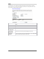
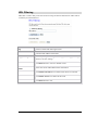
Setup Wizard
The Setup Wizard provides brief and basic configuration of this device, you may enter each
screen to change the default settings. For more detailed settings, you may refer to the
“Configuration via Web” section.
1. View the listed configuration items and click Next to continue.
2. You can setup different modes to LAN and WLAN interface for NAT and bridging function. Then click Next to continue.
12
3. You can maintain the system time by synchronizing with a public time server over the
Internet. Then click Next to continue.
4. Configure the parameters for local area network (If you want to change the default parameters) by entering New IP Address and Subnet Mask. Then click Next to continue.
5. Change the access method (Static IP, DHCP Client, PPPoE or PPTP) by selecting for the
pull-down menu. Then click Next to continue.
13
6. This page is used to configure the parameters for wireless LAN clients which may connect
to your Access Point.
7. To manage your wireless network security by selecting the encryption type (None, WEP,
WPA, WPA2 (AES) and WPA2 Mixed) from the pull-down menu. Click Finished to exit
Setup Wizard screen.
14
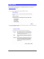
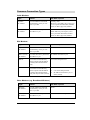
Common Connection Types
Cable Modems
Type
Details
ISP Data required
Dynamic
IP Address
Your IP Address is allocated
automatically, when you connect to you ISP.
Usually, none.
However, some ISP's may require you
to use a particular Hostname, Domain
name, or MAC (physical) address.
Static (Fixed)
IP Address
Your ISP allocates a permanent
IP Address to you.
IP Address allocated to you.
Some ISP's may also require you to
use a particular Hostname, Domain
name, or MAC (physical) address.
Type
Details
ISP Data required
Dynamic
IP Address
Your IP Address is allocated
automatically, when you connect to you ISP.
None.
Static (Fixed)
IP Address
Your ISP allocates a permanent
IP Address to you.
IP Address allocated to you.
PPPoE
You connect to the ISP only
when required. The IP address
is usually allocated automatically.
User name and password.
PPTP
Mainly used in Europe.
You connect to the ISP only
when required. The IP address
is usually allocated automatically, but may be Static (Fixed).
•
PPTP Server IP Address.
•
User name and password.
•
IP Address allocated to you, if
Static (Fixed).
DSL Modems
Other Modems (e.g. Broadband Wireless)
Type
Details
ISP Data required
Dynamic
IP Address
Your IP Address is allocated
automatically, when you connect to you ISP.
None.
Static (Fixed)
IP Address
Your ISP allocates a permanent
IP Address to you.
IP Address allocated to you.
15
16
Operation Mode
You can setup different modes to LAN and WLAN interface for NAT and bridging function.
17
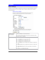
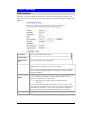
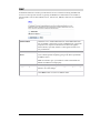
Wireless
Basic Settings
This page is used to configure the parameters for wireless LAN clients which may connect to
your Access Point. Here you may change wireless encryption settings as well as wireless
network parameters.
Disable Wireless
LAN Interface
Check to disable the Access Point function.
The wireless (WLAN) LED on front panel will remain OFF if the
Wireless interface is disabled.
Band
You can choose one mode of the following you need.
z
z
z
z
z
z
2.4GHz (B): 802.11b supported rate only.
2.4GHz (G): 802.11g supported rate only.
2.4GHz (N): 802.11n supported rate only.
2.4GHz (B+G): 802.11b supported rate and 802.11g supported
rate.
2.4GHz (G+N): 802.11g supported rate and 802.11n supported
rate.
2.4GHz (B+G+N): 802.11b, 802.11g and 802.11n supported
rate.
The default is 2.4GHz (B+G+N) mode.
18
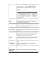
Mode
You can select AP, Client, WDS or AP+WDS mode as you need.
Under the AP mode, you can click the Multiple AP button to
display the Multiple APs list. Default Multiple AP settings are
enabled.
Network Type
Under Client mode this function will be enabled, there is Infrastructure or Ad hoc type can be selected form the pull-down menu.
SSID
A SSID is referred to a network name because essentially it is a
name that identifies a wireless network.
Channel Width
Select 20MHz channel width, the channel number will be form 1~11
and auto; Select 40Mhz channel width the channel number will be
form 1~9 and auto. Default is 20MHz.
Control Sideband
You can select Lower or Upper form the pull-down list.
Channel Number
The channel number base on the channel width you select. Default
channel is 7.
Broadcast SSID
Enabled: This wireless AP will broadcast its SSID to stations.
Disabled: This wireless AP will not broadcast its SSID to stations.
If stations want to connect to this wireless AP, this AP’s SSID
should be known in advance to make a connection.
WMM
The WiFi Multiple Media function is available under 2.4GHz (B),
2.4GHz (G) and 2.4GHz (B+G) band, and is disabled under 2.4GHz
(N), 2.4GHz (G+N) and 2.4GHz (B+G+N) band.
Data Rate
There are several data rate that you can select from the pull-down
menu.
Associated Clients
Click Show Active Clients button to show all the listed active
clients.
Enable Mac Clone
(Single Ethernet
Client)
This function will be enabled under Client mode. Check the box to
enable this function.
Enable Universal
Repeater Mode
This function will be disable under WDS mode. Check the box to
19
(Acting as AP and
client simultaneously)
enable to this function.
SSID of Extended
Interface
When the Enable Universal Repeater Mode (Acting as AP and
client simultaneously) function is enabled, the SSID of Extended
Interface can be entered.
Apply changes
After completing the settings on this page, click Apply changes
button to save the settings.
Reset
Click Reset to restore to default values.
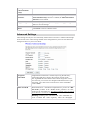
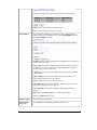
Advanced Settings
These settings are only for more technically advanced users who have a sufficient knowledge
about wireless LAN. These settings should not be changed unless you know what effect the
changes will have on your Access Point.
Fragment
Threshold
Fragmentation mechanism is used for improving the efficiency
when high traffic flows along in the wireless network. If the
802.11g MIMO Wireless Router often transmit large files in wireless network, you can enter new Fragment Threshold value to split
the packet. The value can be set from 256 to 2346. The default
value is 2346.
RTS Threshold
RTS Threshold is a mechanism implemented to prevent the “Hidden Node” problem. If the “Hidden Node” problem is an issue,
please specify the packet size. The RTS mechanism will be activated
if the data size exceeds the value you set.
Warning: Enabling RTS Threshold will cause redundant network overhead that could negatively affect the throughput
20
performance instead of providing a remedy.
This value should remain at its default setting of 2347. Should you encounter inconsistent data flow, only minor modifications of this value are
recommended.
Beacon Interval
Beacon Interval is the amount of time between beacon transmissions. Before a station enters power save mode, the station needs the
beacon interval to know when to wake up to receive the beacon.
Range 20-1024 ms, default is 100.
Preamble Type
A preamble is a signal used in wireless environment to synchronize
the transmitting timing including Synchronization and Start frame
delimiter. You can select Long or Short for the preamble type.
IAPP
Select Enabled or Disabled to execute this function.
Protection
Select Enabled or Disabled to execute the security function.
Aggregation
Select Enabled or Disabled to execute this function.
Short GI
Select Enabled or Disabled to execute this function.
RF Output Power
Select the transmitting power rate 100%, 50%, 25%, 10% or 5%.
Apply changes
After completing the settings on this page, click Apply changes
button to save the settings.
Reset
Click Reset to restore to default values.
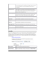
Security
Here you can configure the security of your wireless network. Selecting different method will
enable you to have different level of security. Please note that by using any encryption, by
which data packet is encrypted before transmission to prevent data packets from being eavesdropped by unrelated people, there may be a significant degradation of the data throughput on
the wireless link.
Select SSID
Select the preferred AP from pull-down list.
Apply changes
After completing the settings on this page, click Apply changes
21
button to save the settings.
Reset
Click Reset to restore to default values.
Encryption
Disable: (Encryption is set to Disable by default).
If Use 802.1x Authentication is selected, the RADIUS Server
will proceed to check the 802.1x Authentication.
RADIUS Server IP Address: Please enter the RADIUS Server
IP Address in the field.
RADIUS Server Port: Please enter the RADIUS Server Port,
default server port is 1812.
RADIUS Server Password: Please enter RADIUS Server
Password in the field.
WEP
If WEP encryption is selected, users will have to Set WEP keys
either manually or select to Use 802.1x Authentication to make
the RADIUS server to issue the WEP key dynamically.
Wireless WEP Key Setup:
Key Length: Select the key length from the pull-down menu, either
64-bit or 128-bit.
Key Format: Select Hex if you are using hexadecimal numbers
(0-9, or A-F). Select ASCII if you are using ASCII characters
(case-sensitive).
z
z
z
z
Hexadecimal (64-bit): 10 Hex characters (0~9, a-f).
Hexadecimal (128-bit): 26 Hex characters (0~9, a-f).
ASCII (64-bit): 5 ASCII characters (case-sensitive).
ASCII (128-bit): 13 ASCII characters (case-sensitive).
Encryption Key: To configure your WEP settings. WEP (Wired
Equivalent Privacy) encryption can be used to ensure the
security of your wireless network. Fill in the appropriate value or
22
phrase in Encryption Key field.
Note: You must use the same Key and Encryption settings for the
both sides of the wireless network connection.
WPA
WPA (TKIP/AES): If WPA is selected, users will have to select
the WPA Authentication Modes between Enterprise
(RADIUS) and Personal (Pre-shared Key), and select WPA
Cipher Suite for TKIP or AES. Then enter the WPA Preshared Key in the column to setup the wireless network security
if you select Personal (Pre-shared Key) authentication mode or
enter the Port, IP address and Password if you select the Enterprise (RADIUS) authentication mode.
WPA2 (AES)/WPA2 Mixed
If WPA2 (AES)/WPA2 Mixed is selected from encryption pulldown menu, users will have to select the WPA Authentication
Modes between Enterprise (RADIUS) -set the Port, IP address
and Password, and Personal (Pre-shared Key) –select
Passphrase or Hex (64 characters) then enter the WPA Preshared Key in the column to setup the wireless network security.
WPA (Pre-shared
Key) Format
The WPA (Pre-shared Key) Format will be enabled when WPA,
WPA2 (AES) and WPA2 Mixed encryption be selected.
There are two formats for choice to set the Pre-shared key,
Passphrase and Hex (64 characters). If Hex is selected, users will
have to enter a 64 characters string. For easier configuration, the
Passphrase (at least 8 characters) format is recommended.
WPA Pre-Shared Key Pre-Shared Key serves as a password. Users may key in 8 to 63
characters string if you select Passphrase Pre-shared key format to
set the passwords or leave it blank, in which the 802.1x Authentication will be activated. Make sure the same password is used on
client's end.
Enable PreAuthentication
The two most important features beyond WPA to become
standardized through 802.11i/WPA2 are pre-authentication, which
enables secure fast roaming without noticeable signal latency.
Pre-authentication provides a way to establish a PMK security
association before a client associates. The advantage is that the
client reduces the time that it's disconnected to the network.
Authentication
Port: Enter the RADIUS Server’s port number provided by your
23
RADIUS Server
ISP. The default is 1812.
IP Address: Enter the RADIUS Server’s IP Address provided by
your ISP.
Password: Enter the password that the AP shares with the
RADIUS Server.
Apply changes
After completing the settings on this page, click Apply changes
button to save the settings.
Reset
Click Reset to restore to default values.
Access Control
If you choose 'Allowed Listed', only those clients whose wireless MAC addresses are in the
access control list will be able to connect to your Access Point. When 'Deny Listed' is selected,
these wireless clients on the list will not be able to connect the Access Point.
Wireless Access
Control Mode
Select Allow Listed or Deny List form the pull-down menu to
enable access control function. Default setting is Disable.
MAC Address
Enter the MAC address of a station that is allowed to access this
Access Point.
Comment
You may enter up to 20 characters as a remark to the previous
MAC address.
Apply Changes
After completing the settings on this page, click Apply changes
button to save the settings.
Reset
Click Reset to restore to default values.
Current Access
Control List
This table displays you the station MAC information.
Delete Selected
Click Delete Selected to delete items which are selected.
24
Delete All
Click Delete All to delete all the items.
Reset
Click Reset to rest.
WDS Settings
Wireless Distribution System uses wireless media to communicate with other APs, like the
Ethernet does. To do this, you must set these APs in the same channel and set MAC address of
other APs which you want to communicate with in the table and then enable the WDS. If you
would like to setup this WDS function, please go to Wireless Basic Settings, and then select
the Mode into WDS mode.
Enable WDS
Check the box to enable the WDS function.
MAC Address
MAC Address: Enter the Wireless BSSID (MAC) of the wireless AP
that you want to connect with. To check your wireless router’s MAC
address, please go to Management > Status tab to find your MAC
address.
Data Rate
Select the data rate form the pull-down list.
Comment
Enter a description for the device.
Apply Changes
After completing the settings on this page, click Apply changes button
to save the settings.
Reset
Click Reset to restore to default values.
Set Security
Enable the WDS function and then click Set Security button to set up
the WDS security.
25
WDS Security Setup
Encryption: Select the encryption type None, WEP 64 bits, WEP 128
bits, WPA (TKIP) and WPA2 (AES) from the pull-down menu.
WEP Key Format: For WEP 64 bits and WEP 128 bits encryption
type, the selection of WEP Key Format are Hex and ASCII.
WEP Key: If select Hex if you are using hexadecimal numbers (0-9, or
A-F). Select ASCII if you are using ASCII characters (case-sensitive).
z Hexadecimal (WEP 64 bits): 10 Hex characters (0~9, a~f).
z Hexadecimal (WEP 128 bits): 26 Hex characters (0~9, a~f).
z ASCII (WEP 64 bits): 5 ASCII characters (case-sensitive).
z ASCII (WEP 128 bits): 13 ASCII characters (case-sensitive).
Pre-Shared Key Format: The Pre-shared Key Format will be
enabled when WPA (TKIP) and WPA2 (AES) encryption be selected.
There are two formats for choice to set the Pre-shared key, Passphrase
and Hex (64 characters). If Hex is selected, users will have to enter a
64 characters string. For easier configuration, the Passphrase (at least 8
characters) format is recommended.
Pre-Shared Key: Pre-Shared-Key serves as a password. Users may key
in 8 to 63 characters string to set the passwords or leave it blank, in
which the 802.1x Authentication will be activated. Make sure the same
password is used on client's end.
Apply Changes: Press to save the new settings on the screen.
Close: Click to leave the screen.
Reset: Click to restore the screen.
Show Statistics
Click to show the current WDS AP table. This table shows the MAC
address, transmission packets and errors, reception packets and Tx Rate
(Mbps) counters for each configured WDS AP.
26
Refresh: Click to renew the counters information.
Close: Click to leave the screen.
Current WDS
AP List
Here shows the current WDS AP information.
Delete Selected
Click Delete Selected to delete the selected AP information.
Delete All
Click Delete All to delete all the items.
Reset
Click Reset to restore the settings.
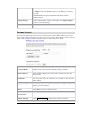
Site Survey
Site survey displays all the active Access Points, MAC, BSSID, Channel, RSSI and Security in
the neighborhood.
Refresh
Check this button to refresh all the Site Survey statistics.
Connect
Select a site that you would like to communicate, and then click
the Connect button.
27
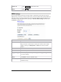
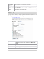
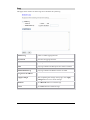
WPS
This page allows you to change the setting for WPS (Wi-Fi Protected Setup). Using this
feature could let your wireless client atomically synchronizes its setting and connect to the
Access Point in a minute without any hassle.
Disable WPS
Check the box to Disable the WPS function, default setting is Enabled.
WPS Status
Here shows the current status of the WPS function.
Self-PIN Number
Here shows the PIN code of the router itself.
Push Button
Configuration
Click Start PBC button to make a WPS connection with client.
Current Key
Information
Here shows current security status that apply on the router.
Client PIN
Number
Enter the client PIN code into the blank field then click the Start PIN
button to make a WPS connection with client.
28
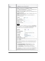
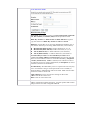
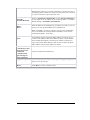
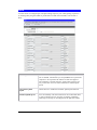
TCP/IP Settings
LAN Interface
This page is used to configure the parameters for local area network which connects to the
LAN port of your Access Point. Here you may change the setting for IP addresss, subnet mask,
DHCP, etc.
IP Address
Shows the IP address of the router.
Subnet Mask
The subnet mask of the router.
Default Gateway
Shows the default gateway IP address.
DHCP
Disabled: Select to disable this Router to distribute IP addresses.
Client: Select to enable the router works as a client.
Server: Select to enable this Router to distribute IP Addresses (DHCP
Server). And the following field will be activated for you to enter the
starting IP Address.
DHCP Client
Range
The starting address of this local IP network address pool. The pool is
a piece of continuous IP address segment. Keep the default value
192.168.1.1 should work for most cases.
•
Maximum: 253. Default value 253 should work for
most cases.
Note: If “Continuous IP address poll starts” is set at 192.168.1.1 and
the “Number of IP address in pool” is 253, the device will distribute IP
addresses from 192.168.1.1 to 192.168.1.253 to all the computers in
the network that request IP addresses from DHCP server (Router)
Show Client
Click to show Active DHCP Client Table.
29
Refresh: Click this button to refresh the table.
Close: Click this button to close the window.
Static DHCP
Select enabled or disabled form pull-down menu, default setting is
disabled. When set to enabled, user can click Static DHCP button to
set the Static DHCP function.
IP Address: Enter the fixed IP address that DHCP Server assigned to a
certain connected station.
MAC Address: Enter the MAC address of a certain station, and then
the DHCP Server will to distribute a fixed IP address to the station
automatically once they connected.
Comment: You can enter a comment to description above IP address
or MAC address.
Apply Changes: After completing the settings on this page, click
Apply changes button to save the settings.
Reset: Click Reset to restore to default values.
Static DHCP List: Here shows the static IP address that have been
assigned according to the MAC address.
Delete Selected: Click Delete Selected to delete items which are
selected.
Delete All: Click Delete All button to delete all the items.
Reset: Click Reset button to rest.
Domain Name
Enter the Domain Name here.
802.1d Spanning Tree
Select Enabled or Disabled from the pull-down menu.
30
Clone MAC
Address
This table displays you the station MAC information.
Apply Changes
After completing the settings on this page, click Apply changes button
to save the settings.
Reset
Click Reset to restore to default values.
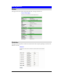
WAN Interface
This page is used to configure the parameters for Internet network which connects to the WAN
port of your Access Point. Here you may change the access method to static IP, DHCP, PPPoE
or PPTP by click the item value of WAN Access type.
WAN Access Type
Host Name
MTU Size
Select the WAN Access Type (Static IP, DHCP Client, PPPoE and
PPTP) from the pull-down menu. Default setting is DHCP Client
enabled.
Enter the host name in this field.
The most appropriate MTU (Maximum Transmission Unit) namely
the maximum packet size, the default value is 1492 for your applica-
31
tion.
Reducing the packet size can help connecting to certain web sites or
speeding up packet transfer rate. If the incorrect packet size is entered,
you may not be able to open certain web sites.
Attain DNS Automatically
Set DNS Manually
DNS 1
DNS 2
DNS 3
Select to Attain DNS Automatically or select Set DNS Manually to
set the DNS server IP address at the following DNS 1~3 columns.
Default setting is Attain DNS Automatically.
Enter the DNS server IP address(es) provided by your ISP, or you can
specify your own preferred DNS server IP address(es).
DNS 2 and DNS 3 servers are optional. You can enter another DNS
server’s IP address as a backup. DNS 2 and DNS 3 servers will be
used when the DNS 1 server fails.
Clone MAC Address
□ Enable uPNP
□ Enable Ipsec pass
through on VPN
connection
□ Enable L2TP
pass through on
VPN connection
Your ISP may require a particular MAC address in order for you to
connect to the Internet. This MAC address is the PC’s MAC address
that your ISP had originally connected your Internet connection to.
Type in this Clone MAC address in this section to replace the WAN
MAC address with the MAC address of that PC.
Check to enable the listed functions.
Apply Changes
After completing the settings on this page, click Apply changes
button to save the settings.
Reset
Click Reset to restore to default values.
32
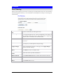
Firewall
Port Filtering
Entries in this table are used to restrict certain types of data packets from your local network to
Internet through the Gateway. Use of such filters can be helpful in securing or restricting your
local network.
Enable Port Filtering
Port Range
Protocol
Comment
Check to enable this port filtering function.
For TCP and UDP Services, enter the beginning of the range of
port numbers used by the service. If the service uses a single port
number, enter it in both the start and finish fields.
Select the protocol (TCP, UDP or Both) used to the remote system
or service.
You may key in a description for the port range.
Apply Changes
After completing the settings on this page, click Apply changes
button to save the settings.
Reset
Click Reset to restore to default values.
Current Filter
Table
Shows the current port filter information.
Delete Selected
Click Delete Selected button to delete items which are selected.
Delete All
Click Delete All button to delete all the items.
Reset
Click Reset button to rest.
33
IP Filtering
Entries in this table are used to restrict certain types of data packets from your local network to
Internet through the Gateway. Use of such filters can be helpful in securing or restricting your
local network.
Enable IP Filtering
Local IP Address
Protocol
Comment
Apply Changes
Reset
Current Filter
Table
Delete Selected
Delete All
Reset
Check to enable IP filtering function.
Enter the local server’s IP address.
Select the protocol (TCP, UDP or Both) used to the remote system
or service.
You may key in a description for the port range.
After completing the settings on this page, click Apply Changes
button to save the settings.
Click Reset button to restore to default values.
Shows the current IP filter information.
Click Delete Selected button to delete items which are selected.
Click Delete All button to delete all the items.
Click Reset button to rest.
34
MAC Filtering
Entries in this table are used to restrict certain types of data packets from your local network to
Internet through the Gateway. Use of such filters can be helpful in securing or restricting your
local network.
Enable MAC Filtering
MAC Address
Comment
Apply Changes
Reset
Current Filter
Table
Delete Selected
Delete All
Reset
Check to enable MAC filtering function.
Enter the client MAC address in the field.
You may key in a description MAC address.
After completing the settings on this page, click Apply Changes
button to save the settings.
Click Reset button to restore to default values.
Shows the current MAC filter information.
Click Delete Selected button to delete items which are selected.
Click Delete All button to delete all the items.
Click Reset button to rest.
35
Port Forwarding
Entries in this table allow you to automatically redirect common network services to a specific
machine behind the NAT firewall. These settings are only necessary if you wish to host some
sort of server like a web server or mail server on the private local network behind your Gateway's NAT firewall.
Enable Port Forwarding
IP Address
Protocol
Port Range
Comment
Apply Changes
Reset
Current Port Forwarding Table
Delete Selected
Delete All
Reset
Check to enable Port Forwarding function.
Enter the IP address in the field.
Select the protocol (TCP, UDP or Both) used to the remote
system or service.
For TCP and UDP Services, enter the beginning of the range of
port numbers used by the service. If the service uses a single
port number, enter it in both the start and finish fields.
You may key in a description MAC address.
After completing the settings on this page, click Apply
Changes button to save the settings.
Click Reset button to restore to default values.
Shows the current Port Forwarding information.
Click Delete Selected button to delete items which are selected.
Click Delete All button to delete all the items.
Click Reset button to rest.
36
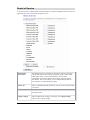
URL Filtering
URL filter is used to deny LAN users from accessing the internet. Block those URLs which
contain keywords listed below.
Enable URL Filtering
URL Address
Apply Changes
Reset
Current Filter
Table
Delete Selected
Delete All
Reset
Check to enable URL filtering function.
Enter the URL address in the field.
After completing the settings on this page, click Apply Changes
button to save the settings.
Click Reset button to restore to default values.
Shows the current URL address filter information.
Click Delete Selected button to delete items which are selected.
Click Delete All button to delete all the items.
Click Reset button to rest.
37
DMZ
A Demilitarized Zone is used to provide Internet services without sacrificing unauthorized
access to its local private network. Typically, the DMZ host contains devices accessible to
Internet traffic, such as Web (HTTP) servers, FTP servers, SMTP (e-mail) servers and DNS
servers.
Enable DMZ
Check the box to enable DMZ function. If the DMZ Host Function is enabled, it means that you set up DMZ host at a particular
computer to be exposed to the Internet so that some applications/software, especially Internet / online game can have twoway connections.
DMZ Host IP Address
Enter the IP address of a particular host in your LAN which will
receive all the packets originally going to the WAN port/Public
IP address above.
Note: You need to give your LAN PC clients a fixed/static IP
address for DMZ to work properly.
Apply Changes
Reset
After completing the settings on this page, click Apply Changes
button to save the settings.
Click Reset button to restore to default values.
38
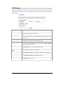
QoS
Use this section to configure QoS. The QoS settings improve your online gaming experience
by ensuring that your game traffic is prioritized over other network traffic, such as FTP or
Web.
Enable QoS
Check the box to enable QoS function. If the DMZ Host Function is enabled, it means that you set up DMZ host at a particular
computer to be exposed to the Internet so that some applications/software, especially Internet / online game can have twoway connections. You can select automatic or manual uplink
speed.
Automatic Uplink
Speed
Check the box to enable the automatic uplink speed function.
Manual Uplink Speed
You can manually enter the transmission rate in the blank field
or select transmission rate, 512 kbps, 1024 kbps, 2048 kbps,
4096 kbps, 6144 kbps or 8192 kbps form the pull-down menu.
39
Management
Status
This page shows the current status and some basic settings of the device.
Statistics
This page shows the packet counters for transmission and reception regarding to wireless and
Ethernet networks.
40
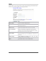
DDNS
Dynamic DNS is a service that provides you with a valid, unchanging, internet domain name
(an URL) to go with that (possibly ever changing) IP-address.
Enable DDNS
Check to enable the DDNS function.
Service Provider
Select the desired DDNS Service Provider DynDNS or TZO
from the pull-down list.
Domain Name
Here shows the domain name of the service provider.
User Name/Email
Enter your email that you registered in service provider
website. (You can refer to below Note information to apply a
account form the service provider website.)
Password/Key
Enter your passwords that you registered in service provider
website. Maximum input is 30 alphanumeric characters (case
sensitive).
Apply Change
After completing the settings on this page, click Apply
Changes button to save the settings.
Reset
Click Reset button to restore to default values.
41
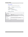
Time Zone Setting
You can maintain the system time by synchronizing with a public time server over the Internet.
Current Time
Enter the current time of this wireless router.
Time Zone Select
Select the local time zone from the pull-down menu.
Enable NTP client
update
Check to enable NTP (Network Time Protocol Server) client
update function.
Automatically Adjust
Daylight Saving
Check the box to enable this function.
NTP server
You may choose to select NTP server from the pull-down menu
or enter an IP address of a specific server manually.
Apply Change
After completing the settings on this page, click Apply Change
button to save current settings.
Reset
Click Reset button to restore to default values.
Refresh
Click Refresh button to renew current time.
42
Denial of Service
A "denial-of-service" (DoS) attack is characterized by an explicit attempt by hackers to prevent
legitimate users of a service from using that service.
Enable DoS
Prevention
DoS (Denial of Service) attacks can flood your Internet connection
with invalid packets and connection requests, using so much bandwidth and so many resources that Internet access becomes
unavailable. The Wireless Router incorporates protection against
DoS attacks. This screen allows you to configure DoS protection.
Check the box to enable the DoS settings.
Select All
After you enabled the DoS prevention, you can click to select all DoS
preventions.
Clear All
After you enabled the DoS prevention, you can click to uncheck all
DoS preventions.
Apply Changes
After completing the settings on this page, click Apply Change
button to save current settings.
43
Log
This page can be used to set remote log server and show the system log.
Enable Log
Check to enable logging function.
System all
Activates all logging functions.
Wireless
Only logs related to the wireless LAN will be recorded.
DoS
Only logs related to the DoS protection will be recorded.
Enable Remote Log
Only logs related to the Remote will be recorded.
Log Server IP address
Apply Changes
After completing the settings on this page, click Apply
Changes button to save current settings.
Refresh
Click Refresh button to renew the logs.
Clear
Click Clear button to delete the logs.
44
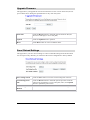
Upgrade Firmware
This page allows you upgrade the Access Point firmware to new version. Please note, do not
power off the device during the upload because it may crash the system.
Select File
Click the Browse button to find and open the firmware file (the
browser will display to correct file path.)
Upload
Click the Upload button to perform.
Reset
Click Reset button to restore to default values.
Save/ Reload Settings
This page allows you save current settings to a file or reload the settings from the file which
was saved previously. Besides, you could reset the current configuration to factory default.
Save Settings to File
Click the Save button to save the current settings file in the PC.
Load Settings form
File
Click the Browse button to find and open the previous saved file
(the browser will display to correct file path.) Then, click Upload
button to upload the previous file.
Reset Settings to
Default
Click Reset button to set the device back to default settings.
45
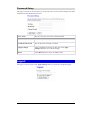
Password Setup
This page is used to set the account to access the web server of Access Point. Empty user name
and password will disable the protection.
User Name
Key in a new login user name in the blank field.
New Password
Maximum input is 36 alphanumeric characters (case sensitive.)
Confirmed Password
Key in the password again to confirm.
Apply Changes
After completing the settings on this page, click Apply
Changes button to save current settings.
Reset
Click Reset button to restore to default values.
Logout
This page is used to logout. Click Apply Change button to logout the configuration page.
46
Chapter 4: PC Configuration
Overview
For each PC, the following may need to be configured:
•
TCP/IP network settings
•
Internet Access configuration
•
Wireless configuration
Windows Clients
This section describes how to configure Windows clients for Internet access via the Wireless
Router.
The first step is to check the PC's TCP/IP settings.
The Wireless Router uses the TCP/IP network protocol for all functions, so it is essential that
the TCP/IP protocol be installed and configured on each PC.
TCP/IP Settings - Overview
If using the default Wireless Router settings and the default Windows
TCP/IP settings, no changes need to be made.
•
By default, the Wireless Router will act as a DHCP Server, automatically providing a
suitable IP Address (and related information) to each PC when the PC boots.
•
For all non-Server versions of Windows, the default TCP/IP setting is to act as a DHCP
client.
If using a Fixed (specified) IP address, the following changes are
required:
•
The Gateway must be set to the IP address of the Wireless Router.
•
The DNS should be set to the address provided by your ISP.
47
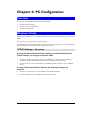
Checking TCP/IP Settings - Windows 2000:
1.
2.
Select Control Panel - Network and Dial-up Connection.
Right - click the Local Area Connection icon and select Properties. You should see a
screen like the following:
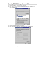
3.
4.
Select the TCP/IP protocol for your network card.
Click on the Properties button. You should then see a screen like the following.
5.
Ensure your TCP/IP settings are correct, as described below.
48
Using DHCP
To use DHCP, select Obtain an IP Address automatically. This is Windows default setting.
Using this setting is recommended. By default, the Wireless Router will act as a DHCP
Server.
Restart your PC to ensure it obtains an IP Address from the Wireless Router.
Using a fixed IP Address ("Use the following IP Address")
If your PC is already configured, check with your network administrator before making the
following changes.
•
Enter the Wireless Router's IP address in the Default gateway field and click OK. (Your
LAN administrator can advise you of the IP Address they assigned to the Wireless Router.)
•
If the DNS Server fields are empty, select Use the following DNS server addresses, and
enter the DNS address or addresses provided by your ISP, then click OK.
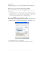
Checking TCP/IP Settings - Windows XP
1.
2.
Select Control Panel - Network Connection.
Right click the Local Area Connection and choose Properties. You should see a screen
like the following:
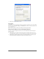
3.
4.
Select the TCP/IP protocol for your network card.
Click on the Properties button. You should then see a screen like the following.
49
5.
Ensure your TCP/IP settings are correct.
Using DHCP
To use DHCP, select the radio button Obtain an IP Address automatically. This is the default
Windows setting. Using this setting is recommended. By default, the Wireless Router will
act as a DHCP Server.
Restart your PC to ensure it obtains an IP Address from the Wireless Router.
Using a fixed IP Address ("Use the following IP Address")
If your PC is already configured, check with your network administrator before making the
following changes.
•
In the Default gateway field, enter the Wireless Router's IP address and click OK. Your
LAN administrator can advise you of the IP Address they assigned to the Wireless Router.
•
If the DNS Server fields are empty, select Use the following DNS server addresses, and
enter the DNS address or addresses provided by your ISP, then click OK.
50
Internet Access
To configure your PCs to use the Wireless Router for Internet access:
•
Ensure that the DSL modem, Cable modem, or other permanent connection is functional.
•
Use the following procedure to configure your Browser to access the Internet via the LAN,
rather than by a Dial-up connection.
For Windows 2000
1.
2.
3.
4.
5.
6.
7.
Select Start Menu - Settings - Control Panel - Internet Options.
Select the Connection tab, and click the Setup button.
Select "I want to set up my Internet connection manually, or I want to connect through a
local area network (LAN)" and click Next.
Select "I connect through a local area network (LAN)" and click Next.
Ensure all of the boxes on the following Local area network Internet Configuration screen
are unchecked.
Check the "No" option when prompted “Do you want to set up an Internet mail account
now?”
Click Finish to close the Internet Connection Wizard.
Setup is now completed.
For Windows XP
1.
2.
3.
4.
5.
6.
7.
8.
9.
Select Start Menu - Control Panel - Network and Internet Connections.
Select Set up or change your Internet Connection.
Select the Connection tab, and click the Setup button.
Cancel the pop-up "Location Information" screen.
Click Next on the "New Connection Wizard" screen.
Select "Connect to the Internet" and click Next.
Select "Set up my connection manually" and click Next.
Check "Connect using a broadband connection that is always on" and click Next.
Click Finish to close the New Connection Wizard.
Setup is now completed.
Accessing AOL
To access AOL (America On Line) through the Wireless Router, the AOL for Windows software must be configured to use TCP/IP network access, rather than a dial-up connection. The
configuration process is as follows:
•
Start the AOL for Windows communication software. Ensure that it is Version 2.5, 3.0 or
later. This procedure will not work with earlier versions.
•
Click the Setup button.
•
Select Create Location, and change the location name from "New Locality" to "Wireless
Router".
•
Click Edit Location. Select TCP/IP for the Network field. (Leave the Phone Number
blank.)
•
Click Save, then OK.
Configuration is now complete.
•
Before clicking "Sign On", always ensure that you are using the "Wireless Router" location.
51
Macintosh Clients
From your Macintosh, you can access the Internet via the Wireless Router. The procedure is as
follows.
1. Open the TCP/IP Control Panel.
2. Select Ethernet from the Connect via pop-up menu.
3. Select Using DHCP Server from the Configure pop-up menu. The DHCP Client ID field
can be left blank.
4. Close the TCP/IP panel, saving your settings.
Note:
If using manually assigned IP addresses instead of DHCP, the required changes are:
•
Set the Router Address field to the Wireless Router's IP Address.
•
Ensure your DNS settings are correct.
Linux Clients
To access the Internet via the Wireless Router, it is only necessary to set the Wireless Router
as the "Gateway".
Ensure you are logged in as "root" before attempting any changes.
Fixed IP Address
By default, most Unix installations use a fixed IP Address. If you wish to continue using a
fixed IP Address, make the following changes to your configuration.
•
Set your "Default Gateway" to the IP Address of the Wireless Router.
•
Ensure your DNS (Name server) settings are correct.
To act as a DHCP Client (recommended)
The procedure below may vary according to your version of Linux and X -windows shell.
1. Start your X Windows client.
2. Select Control Panel - Network
3. Select the "Interface" entry for your Network card. Normally, this will be called "eth0".
4. Click the Edit button, set the "protocol" to "DHCP", and save this data.
5. To apply your changes
•
Use the "Deactivate" and "Activate" buttons, if available.
•
OR, restart your system.
Other Unix Systems
To access the Internet via the Wireless Router:
• Ensure the "Gateway" field for your network card is set to the IP Address of the Wireless
Router.
•
Ensure your DNS (Name Server) settings are correct.
52
Wireless Station Configuration
This section applies to all Wireless stations wishing to use the Wireless Router's Access Point,
regardless of the operating system which is used on the client.
To use the Wireless Access Point in the Wireless Router, each Wireless Station must have
compatible settings, as follows:
Mode
The mode must be set to Infrastructure.
SSID (ESSID)
This must match the value used on the Wireless Router. The default
value is Untitled
Note! The SSID is case sensitive.
WEP
WPA
WPA2 (AES)
WPA2 Mixed
By default, WEP on the Wireless Router is disabled.
•
If WEP remains disabled on the Wireless Router, all stations must
have WEP disabled.
•
If WEP is enabled on the Wireless Router, each station must use the
same settings as the Wireless Router.
WPA (TKIP/AES)/ WPA2 (AES)/ WPA2 Mixed: If one of these
securities is enabled on the Wireless Router, each station must use the
same settings as the Wireless Router. If there is no security is enabled on
the Wireless Router, the security of each station should be disabled as
well.
Note: By default, the Wireless Router will allow both 802.11b,802.11g and
802.11n connections.
53
Appendix A:
Troubleshooting
A
Overview
This chapter covers some common problems that may be encountered while using the Wireless
Router and some possible solutions to them. If you follow the suggested steps and the Wireless
Router still does not function properly, contact your dealer for further advice.
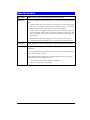
General Problems
Problem 1:
Can't connect to the Wireless Router to configure it.
Solution 1:
Check the following:
•
The Wireless Router is properly installed, LAN connections are OK,
and it is powered ON.
•
Ensure that your PC and the Wireless Router are on the same network
segment. (If you don't have a router, this must be the case.)
•
If your PC is set to "Obtain an IP Address automatically" (DHCP
client), restart it.
•
If your PC uses a Fixed (Static) IP address, ensure that it is using an IP
Address within the range 192.168.1.1 to 192.168.1.253 and thus compatible with the Wireless Router's default IP Address of 192.168.1.254.
Also, the Network Mask should be set to 255.255.255.0 to match the
Wireless Router.
In Windows, you can check these settings by using Control PanelNetwork to check the Properties for the TCP/IP protocol.
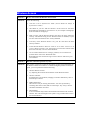
Internet Access
Problem 1:
When I enter a URL or IP address I get a time out error.
Solution 1:
A number of things could be causing this. Try the following troubleshooting
steps.
•
Check if other PCs work. If they do, ensure that your PCs IP settings
are correct. If using a Fixed (Static) IP Address, check the Network
Mask, Default gateway and DNS as well as the IP Address.
•
If the PCs are configured correctly, but still not working, check the
Wireless Router. Ensure that it is connected and ON. Connect to it and
check its settings. (If you can't connect to it, check the LAN and power
connections.)
•
If the Wireless Router is configured correctly, check your Internet
connection (DSL/Cable modem etc) to see that it is working correctly.
Problem 2:
Some applications do not run properly when using the Wireless Router.
Solution 2:
The Wireless Router processes the data passing through it, so it is not
transparent.
Use the Special Applications feature to allow the use of Internet applications
which do not function correctly.
If this does solve the problem you can use the DMZ function. This should
work with almost every application, but:
•
It is a security risk, since the firewall is disabled.
•
Only one (1) PC can use this feature.
55
Wireless Access
Problem 1:
My PC can't locate the Wireless Access Point.
Solution 1:
Check the following.
•
Your PC is set to Infrastructure Mode. (Access Points are always in
Infrastructure Mode)
•
The SSID on your PC and the Wireless Access Point are the same.
Remember that the SSID is case-sensitive. So, for example "Workgroup"
does NOT match "workgroup".
•
Both your PC and the Wireless Router must have the same setting for
security. The default setting for the Wireless Router is disabled, so your
wireless station should also have security disabled.
•
If security of the Wireless Router is on, your PC must have the same
security enabled.
•
If the Wireless Router's Wireless screen is set to Allow LAN access to
selected Wireless Stations only, then each of your Wireless stations must
have been selected, or access will be blocked.
•
To see if radio interference is causing a problem, see if connection is
possible when close to the Wireless Router.
Remember that the connection range can be as little as 100 feet in poor
environments.
Problem 2:
Wireless connection speed is very slow.
Solution 2:
The wireless system will connect at the highest possible speed, depending on
the distance and the environment. To obtain the highest possible connection
speed, you can experiment with the following:
•
Wireless Router location.
Try adjusting the location and orientation of the Wireless Router.
•
Wireless Channel
If interference is the problem, changing to another channel may show a
marked improvement.
•
Radio Interference
Other devices may be causing interference. You can experiment by
switching other devices Off, and see if this helps. Any "noisy" devices
should be shielded or relocated.
•
RF Shielding
Your environment may tend to block transmission between the wireless
stations. This will mean high access speed is only possible when close to
the Wireless Router.
56
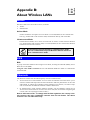
Appendix B:
About Wireless LANs
B
Modes
Wireless LANs can work in either of two (2) modes:
•
Ad-hoc
•
Infrastructure
Ad-hoc Mode
Ad-hoc mode does not require an Access Point or a wired (Ethernet) LAN. Wireless Stations (e.g. notebook PCs with wireless cards) communicate directly with each other.
Infrastructure Mode
In Infrastructure Mode, one or more Access Points are used to connect Wireless Stations
(e.g. Notebook PCs with wireless cards) to a wired (Ethernet) LAN. The Wireless Stations
can then access all LAN resources.
Access Points can only function in "Infrastructure" mode,
and can communicate only with Wireless Stations which are
set to "Infrastructure" mode.
BSS
BSS
A group of Wireless Stations and a single Access Point, all using the same ID (SSID), form a
Basic Service Set (BSS).
Using the same SSID is essential. Devices with different SSIDs are unable to communicate
with each other.
Channels
The Wireless Channel sets the radio frequency used for communication.
•
•
Access Points use a fixed Channel. You can select the Channel used. This allows you to
choose a Channel which provides the least interference and best performance. In the USA
and Canada, 11 channel are available. If using multiple Access Points, it is better if adjacent Access Points use different Channels to reduce interference.
In "Infrastructure" mode, Wireless Stations normally scan all Channels, looking for an
Access Point. If more than one Access Point can be used, the one with the strongest signal
is used. (This can only happen within an ESS.)
Note to US model owner: To comply with US FCC regulation, the country selection function has been completely removed from all US models. The above
function is for non-US models only.
Security
WEP
WEP (Wired Equivalent Privacy) is a standard for encrypting data before it is transmitted. This
is desirable because it is impossible to prevent snoopers from receiving any data which is
transmitted by your Wireless Stations. But if the data is encrypted, then it is meaningless
unless the receiver can decrypt it.
If WEP is used, the Wireless Stations and the Access Point must have the same settings
for each of the following:
WEP
64 Bits, 128 Bits.
Key
For 64 Bits encryption, the Key value must match.
For 128 Bits encryption, the Key value must match.
WEP Authentication
Open System or Shared Key.
WPA/WPA2
WPA/WPA2 (Wi-Fi Protected Access) is more secure than WEP. It uses a “Shared Key”
which allows the encryption keys to be regenerated at a specified interval. There are four
encryption options: TKIP, AES, TKIP-AES and additional setup for RADIUS is required in
this method.
WPA-PSK/WPA2-PSK
WPA/WPA2 (Wi-Fi Protected Access using Pre-Shared Key) is recommended for users who
are not using a RADIUS server in a home environment and all their clients support
WPA/WPA2. This method provides a better security.
Encryption
TKIP
AES
WEP Key 1~4
Passphrase
NOT REQUIRED
8-63 characters
802.1x
With 802.1x authentication, a wireless PC can join any network and receive any messages that
are not encrypted, however, additional setup for RADIUS to issue the WEP key dynamically
will be required.
58
Wireless LAN Configuration
To allow Wireless Stations to use the Access Point, the Wireless Stations and the Access Point
must use the same settings, as follows:
Mode
On client Wireless Stations, the mode must be set to "Infrastructure".
(The Access Point is always in "Infrastructure" mode.)
SSID (ESSID)
Wireless Stations should use the same SSID (ESSID) as the Access
Point they wish to connect to, but the SSID can not set to be null (blank).
WEP
The Wireless Stations and the Access Point must use the same settings
for WEP (64 Bit, 128 Bit).
WEP Key: If WEP is enabled, the Key must be the same on the Wireless Stations and the Access Point.
WEP Authentication: If WEP is enabled, all Wireless Stations must
use the same setting as the Access Point (either "Open System" or
"Shared Key").
WPA
WPA2 (AES)
WPA2 Mixed
WPA (TKIP/AES)/ WPA2 (AES)/ WPA2 Mixed: If one of these securities is enabled on the Wireless Router, each station must use the same
settings as the Wireless Router. If there is no security is enabled on the
Wireless Router, the security of each station should be disabled as well.
59
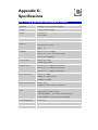
Appendix C:
Specifications
802.11n/b/g Wireless Broadband Router
Standards
IEEE 802.11 n/b/g standards compliant
Antenna
2 Dipole antennas( 2dBi)
Security
WEP 64, 128
WPA, WPA2
Frequency Range
2.400 ~ 2.4835GHz ( subject to local regulations)
Number of Selectable
Channels
USA and Canada – 11
Most European countries – 13
Japan – 14
Data Rate
802.11b: 1, 2, 5.5, 11Mbps
802.11g: 6, 9, 12, 18, 24, 36, 48, 54Mbps
802.11n: up to 300Mbps
Coverage Area
Indoor: up to 100M
Outdoor: up to 300M
Transmit Power
802.11g : 15 +/- 1.5dBm @ normal temp
802.11b : 19 +/- 1.5dBm @ normal temp
802.11n : 13 +/- 1.5dBm @ normal temp
Receiver Sensitivity
11Mbps @ -85dBm
54Mbps @ -73dBm Typtical
300Mbps @ -68dBm
Physical Specifications
Weight : 150g
Dimension : 150(L)* 106(W)* 27(H) mm
Environment Specifications
Operating Temp : 0OC to 50 OC
Storage Temp : -20 OC to 70 OC
Operating Humidity : 10% to 90% Non-Condensing
Storage Humidity : 5% to 90% Non-Condensing
Power Requirement
DC 12V/1A
Certifications:
FCC, CE
Warranty
12 months
C
Appendix B - Specifications
61