1
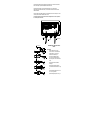
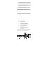
PSM INSTRUMENTATION LTD
HYDROSTATIC
LEVEL TRANSMITTERS
USER MANUAL
Issue B date: 18/04/2000
Burrell Road Industrial Estate
Haywards Heath, West Sussex RH16 1TW, UK
Tel: +44 (0)1444 410040 Fax: +44 (0)1444 410121
Http://www.psm-sensors.co.uk E-mail: [email protected]
1
Doc Ref: Man 01
CONTENTS
SECTION
TITLE
PAGE
1.0
Introduction
4
2.0
Model Designation and Options
4
3.0
General Specifications
4
4.0
Installation
5
4.1
Mechanical Installation
5
4.2
Electrical Installation
6
5.0
Commissioning
6.0
Recalibration
10
7.0
Intrinsic Safety
11
8.0
General Operation & Maintaence
13
Fault Finding
14
Sensor/Amplifier Module Replacement
16
9.0
10.0
9
Warranty Conditions
17
General Outline Drawings
17
General Do’s and Dont’s
18
3
1.0 INTRODUCTION
PSM 200/300 Series level transmitters are designed for monitoring liquid levels on a wide range
of applications. The measurement principle is based on a pressure sensitive diaphragm which is
deflected by the applied hydrostatic pressure.
Attached to the other side of the diaphragm and not exposed to the process is a ferro-magnetic core.
This core is positioned centrally within a high resolution Linear Variable Differential Transformer.
The LVDT has a central primary and a secondary coil at each end. Movement of the diaphragm is a
change in magnetic flux and hence output voltage from the secondaries.
This output signal is then processed in the remote amplifier module to provide an industry
standard 4-20mA signal with range and zero adjustment facilities.
A extensive range of design features and optional mounting components are available to meet
the differing needs of particular applications.
The product is designed and approved for use in hazardous I.S. classified duties to EEx ia llC T5
where specified and carries a number of Marine Society "Type" Approvals.
2.0 MODEL DESIGNATION
Each transmitter amplifier module bears an identification plate which carries both the model
code and a unique serial number.
Note: The sensor is also marked with the Serial Number and the units MUST be
employed as a matched pair to preserve factory calibration.
In addition, the Model Code may be suffixed by a V number. This indicates a variation from
standard product, for example a special process connection for a particular duty. Where a V code
is found the accompanying order paperwork will identify it.
GENERAL SPECIFICATIONS
3.1 Sensor Assembly
Body:
316 stainless steel construction. Optionally Hastelloy.
Diaphragm:
Hastelloy C276, Inconel X750 or 316 stainless steel
Mounting:
Internally via pole, clamp or cable suspension.
Externally via threaded or flanged process connection
Overload:
Minimum 5 x nominal range.
Operating temp:
-25 to +95oC standard. Option -80 to 150oC.
3.2. Sensor Cable
Construction:
Depending on duty either 4 core with overall screen
or 2 core and miniature coaxial with overall screen.
Integral breather tube for atmospheric reference.
Outer sheathing either in XLPE or `Hytrel' Teflon.
Maximum length: 100m. (200m to special order)
4
3.3. Electronics Module
Housing:
GRP surface mounting to IP65 (optionally IP67)
Connection:
1 x PG9 gland for sensor cable. 1 x PG9 gland for atmospheric reference
1 x PG9 gland for 4-20mA output (optionally PG11, PG13.5 or PG16)
Power requirement:
12-30 V dc.
Signal output:
2 wire 4 to 20mA.dc.
Maximum load:
Dependent on supply (1000 ohms at 30V DC)
Range adjustment:
3 to 1 electronic turndown of sensor nominal range.
Zero adjustment:
±10% of set span.
3.4. Performance
Maximum Error:
± 0.25% of full range output (Optional 0.1% some variants)
Temp Coefficient:
Less than 0.05%/deg.c. range & zero (Optional 0.02%)
INSTALLATION
Pre-installation checks
Prior to installation it is recommended that the following checks are made.
Ensure that the factory calibration is in accordance with the process parameters and tank height.
Of particular importance is the transmitter fitting position and orientation (horizontal or vertical).
Any discrepancies will result in inaccuracy.
Ensure that the correct length of cable has been fitted to the sensor
Note: The cable is factory fitted to ensure a pressure tight seal on the submersible sensors.
NO ATTEMPT SHOULD BE MADE TO REMOVE THE CABLE GLAND.
Each transducer and transmitter are factory calibrated as a matched pair and for both carry the
same serial number. It should be ensured that these match.
4.1. MECHANICAL INSTALLATION
Sensor cable
The cable which is factory fitted to the transducer is purpose designed for the application. It
contains a nylon vent tube which provides an atmospheric reference for the sensor. The cable
construction is of sufficient strenght to enable the sensor to be directly suspended in deep wells
and reservoirs. The outer sheathing is a special material suitable for continuous immersion in water,
and many oils and chemicals. When handling the cable take special care not to damage the outer
sheathing. Do not bend the cable to a radius less than 50mm.
5
When a transmitter is suspended by its cable use a proprietary suspension cleat or wind three or
four turns around a 100mm diameter pipe or drum. Where the cable is to be brought through to
the tank wall it is recommended that where possible this be done above the maximum fill line
using a suitable compression fitting. (Available from PSM)
4.1.1. Sensor fitting height
As previously stated, when a transmitter is used in tank level or volume applications it is important
to ensure that the sensor is fitted at a known position and height above the bottom of the tank. All
calibration data will be related to this fitting information.
4.1.2. Mounting
During installation the transducer should be handled with great care, especially the sensitive
diaphragm assembly. Any damage to this will affect the performance and accuracy of the
Instrument. Particular care should be taken with sensors which have a protective non-porous
coating on wetted parts. Any attempt to remove this coating or any surface scratches will
permanently damage the unit.
When mounting the unit ensure that suitable gaskets or sealants are employed to provide pressure
tight seals. The sensor should not be mounted where it will be subject to excessive or continuous
vibration, extreme temperature fluctuation or risk of mechanical damage.
Important note for Marine Duties
For shipboard applications, especially where a cathodic protection system is employed, it
is vital that the sensor body is firmly earth bonded to the hull. Failure to observethis will
result in electrolytic corrosion of the unit. Where necessary an earth strap must be
employed.
4.1.3. Electronic Transmitter
The RT168A provides the excitation supply for the sensor and amplifies and conditions the return
signal to provide a standard 4-20mA output. The unit is housed in a weatherproof GRP enclosure
suitable for wall mounting. Fixing details are given at the rear of the manual. In general this unit
should be mounted away from extremes of temperature, eg. Not in direct sunlight, vibration, or
where likely to be continuously sprayed with water. (in the last case an optional IP67 enclosure is
available)
4.2. ELECTRICAL INSTALLATION
The unit should be wired in accordance with the following diagrams. The sensor cable is
terminated in the RT168A electronic transmitter following the wire colour code marked on the
printed circuit card.
The sensor cable consists of :
Black conductor Red conductor Coaxial conductor(green)Coaxial screen -
6
connect to EXconnect to EX+
connect to OP+
connect to OP-
The overall cable screen must be terminated at the PG9 entry gland. Particular care should be
taken in this respect to preserve the RFI/EMC standards of the unit.
The cable also incorporates a nylon vent tube which should be cut to a free length of
approximately 20mm within the enclosure, it must be ensured that this tube is not blocked or
otherwise restricted.
The sensor cable will have been supplied to suit the installation, and since it forms part of a tuned
circuit any excess should be coiled rather than cut back.
The following diagrams illustrate the termination arrangements and correct procedure
for connecting the sensor cable.
TRANSDUCER
RANGE
EX- EX+ OP+ OP-
SCREEN
GREEN
RED
BLACK
A
B
C
INDICATOR
+ mA Test Points
OUTPUT SIGNAL
4 to 20 mA
10-35 Volts
DC Input
ZERO
Sensor Input
cable
(PSM supply)
Sintered Breather
Port
TERMINATION OF INPUT AND OUTPUT
CABLES
INPUT CABLE ASSY.
Fig 1
50 - 55
40
20
Screen
Input Cable:
Remove outer sheath, trim outer
screen to 20mm. Cut vent tube end at
45 deg 40mm long. Cut and strip
wires and inner screen as Fig 1.
10
vent
Black
Red
Green
Fig 2
30
Inner screen
17
Fig 3
Cable - 2 core / screen
(Customer supply)
Fit 20mm clear heatshrink tube to
inner screen. Fit bootlace ferrules to
black, red green & inner screen ends and
crimp.
bootlace
ferrules
Fit cable gland locknut and rubber
sleeve Fig 2.
Fig 4
Fit cable gland inner sleeve and fold
outer screen wires back over sleeve as Fig
3.
Fig 5
Fit cable gland body over wires & vent as
Fig 4. (‘O’ ring to outside)
Tighten cable gland in position as Fig 5.
7
Output cable:
As input cable omittng inner screen and vent tube. Output cable screen must be
earthed at supply end
Important
The case is vented. It should be positioned with the glands on the underside to prevent
direct ingress of moisture. Alternatively, an extended vent tube, (customer supply), must
be fitted in areas where flooding or hose wash down are likely.
6mm (1/4”) od plastic tube is suitable and should run to a dry area which is at the same
atmosheric pressure as within the tank.
(The sintered plug must be removed in this case)
The signal/power loop should be connected as shown in the following diagram. Two core
screened cable should be used with a minimum conductor size of 0.5mm. A larger conductor size may
be employed to reduce loop impedance. All connection should be made in series as illustrated.
The screen of the signal cable should be connected to the cable gland as described for
the sensor cable.
TRANSDUCER
RANGE
+ mA -
EX- EX+ OP+ OP-
SCREEN
GREEN
RED
BLACK
A
B
C
INDICATOR
Test Points
OUTPUT SIGNAL
4 to 20 mA
10-35 Volts
DC Input
ZERO
Sensor Input
cable
(PSM supply)
Cable - 2 core / screen
(Customer supply)
Sintered Breather
Port
screen to be terminated
to cable gland
NOTE:
24V dc
Supply
A PG9 cable gland is fitted as standard for the output signal cable.
However, if specified, a larger gland
may be fitted during manufacture.
Following wiring the lid must always
be refitted and tightly sealed
Connect cable
screen at supply
end only
Auxiliary equipment
8
4.2.1.Power Supply
The transmitter requires a nominal supply of 24V.dc. but will operate between 12V to 30 V dc.
The maximum permissible loop impedance for a given supply is derived from the following
equation:.
Supply Volts - 12
0.02
= Load in ohms.
4.2.2.Integral Indicator
The three terminals A,B,C are for connection of the lid mounted 3.1/2 digit indicator which may be
specified as an option. Where fitted this will be pre-wired, no other connection may be made to
these terminals.
N.B.This is a non-IS approved item.
4.3. Atmospheric Reference
A further central PG9 gland is fitted to the RT168A enclosure. As standard this should be fitted
with the sintered breather plug also supplied. This plug allows the enclosure to `breathe' without
allowing moisture to enter, thus providing (via the sensor cable) an atmospheric reference for the
reverse side of the sensing diaphragm.
NOTE: This reference pressure is essential to the accurate operation of the transmitter
If it is likely that the area in which the RT168A is located will be permanently wet, or at times
submerged, then the vent plug must be replaced by a 6mm O.D. breather tube of nylon, copper or
similar. This tube must be routed to, and terminated in a permanently dry area.
For certain shipboard applications eg., double bottom tanks, or where the amplifier in air
conditioned areas, it must be ensured that the atmospheric pressure at the termination
point of the vent line is always the same as that within the tank being monitored. Any
differential will cause a directly proportional error of measurement.
Note: Some units are supplied as “Absolute” devices. These do not require the atmospheric
reference pipe (although it will be present in the cable) as they are calibrated from
Absolute Zero Pressure. The monitoring system they are connected to should also include
a barometric transmitter to allow for correction of atmospheric pressure.
5.0 COMMISSIONING
Each instrument is normally manufactured and calibrated in accordance with its intended
application and should not need any further setting up. However it may be that an examination
of the actual installation reveals some differences from original design criteria. If this is the case
then the range and zero may be adjusted to suit.
9
5.1. Zero adjustment
These instruments are of the "live zero" type, therefore, with power applied and no head pressure a
4.00mA signal should be present.
NOTE: The current output should be measured using an accurate digital meter in
preference to the loop indicator since this may have been calibrated to take into account
volume below the transmitter fitting height. In this case, 4.00mA would NOT represent a
zero display.
Test pins marked + & - are provided on the RT168A terminal board to allow monitoring of the
4-20mA loop without disconnecting the signal lines. Where the signal at zero (i.e., no head
pressure) is not 4.00mA correction can be made by adjustment of the zero potentiometer which
can be found in the bottom right hand corner of the RT168 transmitter.
5.2. Range adjustments
The actual calibrated range of the instrument will be found on the identification plate of the
RT168A.
Where it is necessary to adjust the range due to changes in the installation, the liquid level should
be raised accurately to the required 100% level and the range potentiometer in the top right hand
corner of the transmitter, adjusted to provide a 20.00mA output signal.
Where it is impractical to adjust the actual liquid level, a suitable pressure source such as a dead
weight tester or mercury column may be employed. The pressure connection required for this will
depend upon the transmitter type, and PSM can provide a suitable adaptor where necessary.
NOTE: Where it is suspected that range and/or zero settings are not correct, before
making any adjustments, do first ensure that the transmitter does not have a "special"
calibration. For example, some transmitters because of their mounting position relative to
the liquid head may be calibrated with either a positively or negatively offset zero, such
that at zero head pressure the output is above 4.00mA, or a certain amount of pressure is
required before the signal moves away from the 4.00mA point.
6.0 RECALIBRATION
Where the instrument has to be recalibrated for any reason the following procedure should
be followed:i)
With no process pressure applied turn the range adjustment control fully clockwise and
then by adjustment of the zero potentiometer set the output signal to 4.00mA. For
applications where a raised zero is required it must first be established by calculation
what signal output is required for zero process pressure. This is then set using the zero
control as defined above. For applications where a suppressed zero is required again it
must be established what the process pressure should be for 4.00mA signal and this should
be applied prior to setting the zero as above.
10
ii)
Apply a pressure to the transmitter equivalent to its full nominal range which will be
found on the identification plate, and set 20.00mA output using the range potentiometer.
Release the pressure and recheck the zero point making any minor adjustment necessary.
iii)
Run the pressure up and down again checking the linearity of the instrument at 25%,
50% and 75% of nominal range. No adjustment of linearity is possible by the user, where
the instrument is thought to be out of limits refer to PSM.
iv)
Now apply a pressure equal to the full actual range required and by adjustment of the
range potentiometer set the output signal to 20.00mA.
NOTE: When determining the actual range ensure that the specific gravity of
the actual process fluid is accounted for.
7.0 INTRINSIC SAFETY
360 Series transmitters are covered by intrinsically safe certification for use in hazardous areas.
Approval certification.
RT168A Amplifier
BAS No Ex 86B2028
CODE EEx ia IIC T5
Series 300 Sensors
BAS No Ex 86B2029
CODE EEx ia IIC T6
The above approval codes are defined as follows:E-
Indicates the CENELEC standard.
Ex ia -
Indicates that the equipment cannot cause ignition in
normal operation or with any combination of up to two
faults applied. Refer to BS5501 Part 7 and EN50020.
IIC -
Indicates the group of gases/vapours defined in
BS5502 Part 1 and EN50019.
T5 -
Indicates the maximum surface temperature category as
defined in BS4683 Part 1.
The following is a reproduction of the schedule for certificate of assurance No EX86030 which
covers installation criteria. A full copy of the certificate ia available on request.
ISOLATED
POWER SUPPLY
PRESSURE SENSOR
SERIES 200/300
PRESSURE TRANSMITTER
RT168 OR RT861
Ex 86B2029
Ex 86B2028
OP+
SAFE AREA APPARATUS
INPUT+
OP-
INPUT-
SUPPLY+
APPARATUS WHICH IS UNSPECIFIED
EXCEPT THAT IT MUST NOT BE
SUPPLIED FROM NOR CONTAIN IN
NORMAL OR ABNORMAL CONDITIONS
A SOURCE OF POTENTIAL WITH
RESPECT TO EARTH IN EXCESS OF
250 VOLTS R.M.S. OR 125 VOLTS DC
SUPPLYHAZARDOUS AREA
SAFE AREA
11
NOTES
1 THE ELECTRICAL CIRCUIT IN THE HAZARDOUS AREA MUST BE CAPABLE OF WITHSTANDING AN
A.C. TEST VOLTAGE OF 500 VOLTS RMS TO EARTH OR FRAME FOR A PERIOD OF ONE MINUTE.
2 THE CAPACITANCE AND EITHER THE INDUCTANCE OR THE INDUCTANCE TO RESISTANCE (L/R)
RATIO OF THE HAZARDOUS AREA CABLE MUST NOT EXCEED THE VALUES GIVEN IN TABLE 1.
3 THE INSTALLATION MUST COMPLY WITH THE INSATALLION REQUIREMENTS AS SPECIFIED IN
BSEN 60079-14 1997
4 ANY ONE OF THE FOLLOWING POWER SUPPLIES MAY BE USED:
AN MTL2441B REPEATER POWER SUPPLY,BASEEFA CERTIFICATE NO Ex92C2462
AN MTL3041 REPEATER POWER SUPPLY,BASEEFA CERTIFICATE NO Ex86B2031
AN MTL4041 REPEATER POWER SUPPLY,4-20mA,BASEEFA CERTIFICATE NO Ex92C2003
AN MTL5041 REPEATER POWER SUPPLY,4-20mA,BASEEFA CERTIFICATE NO Ex95D2339
A CAMILLE BAUER AG SUPPLY UNIT SINEAX B811 TYPE B811-13 OR TYPE B811-14.
CERTIFICATE NO. PTB 97 ATEX 2083
N.B. THE CAMILLE BAUER AG SUPPLY UNIT SINEAX B811 TYPE B811-1... , ALTHOUGH MEETING THE
SEGREGATION REQUIREMENTS FOR UNSPECIFIED SAFE AREA APPARATUS OF 375V PEAK, IS SUBJECT
TO OPERATIONAL LIMITATIONS OF VOLTAGE. FOR DETAILS SEE THE CERTIFICATE
SEE TABLE 2 FOR CONNECTION DETAILS.
TABLE 1
GROUP
CAPACITANCE uF
INDUCTANCE mH OR L/R RATIO (MICROHENRIES/OHM)
IIC
0.13
0.37
IIB
0.39
1.11
24
72
IIC
1.04
2.96
192
TABLE 2
TERMINAL NUMBERS
POWER SUPPLY
HAZARDOUS
AREA
CONNECTIONS
SAFE AREA CONNECTIONS
REFERENCE N0.
SUPPLY+ SUPPLY- OUTPUT+ OUTPUT- INPUT+ INPUTMTL2441B
15
16
13
14
3
5
MTL3041
3
4
1
2
5
6
MTL4041
CON2
PIN14
CON2
PIN13
CON2
PIN9
CON2
PIN11
CON1
PIN2
CON1
PIN5
MTL5041
CON5
PIN14
CON5
PIN13
CON4
PIN12
CON4
PIN11
CON1
PIN2
CON1
PIN1
9
4
6
1
SINEAX B811
TYPE B811-13 OR
TYPE B811-14
10
5
12
8. GENERAL OPERATION & MAINTENANCE
Where correctly installed, satisfactory continuous performance over a long period may be expected
from these transmitters. None of the units have any specific maintenance requirement. However,
following periodic checks are recommended to good working order.
I)
The system components should be checked visually for good condition of the housings
(ensuring that doors and lids are kept firmly closed). Check that weatherproof gasketsand
seals are in good condition and secure.
ii)
Electrical cable runs between the system components should be inspected for condition
and security and that cable glands are securely fastened.
iii)
If the sensor is to be used in an application where the accumulation of sludge may be
formed in transmitter pressure chamber after a period of time, cleaning may be
necessary, otherwise a slow response to level changes or an inaccurate reading may
result.
The cleaning procedure is as follows:
a)
Remove the transmitter from service. Clean and dry the unit externally using clean
water or suitable solvents.
b)
Where fitted, by hand only, carefully unscrew the pressure sensors end cover or flange plate
from the front of the transducer. If the `0' ring seal has stuck use a hide faced hammer to
lightly tap around the rim. Never attempt to use sharp or hard steel tools to remove this
cover.
DO NOT INSERT ANY TOOLS OR OBJECTS THROUGH THE SENSOR
END CAP OR THE FRONT PROTECTION GUARD.
When unscrewed keep the assembly parallel and gently lift away from the body exposing
the diaphragm.
13
c)
Using suitable solvents or clean water only, carefully clean the sludge deposits from the
exposed diaphragm or pressure chamber (depending upon model). Great care must be
taken not to damage, distort, or otherwise manipulate the diaphragm.
d)
Clean and inspect any gaskets or seals and ensure that the seating is thoroughly cleaned.
Replace seals if necessary.
e)
When refitting the end cover or flange plate ensure that it is kept parallel and clear of the
diaphragm. The assembly should be hand tight only.
It is further recommended that system calibration should be checked at least once a year following
the procedure given under section 6.0, entitled ‘Recalibration’
9.0. FAULT FINDING
Each instrument is exercised and calibrated in accordance with the application requirements. As
such it is fully tested prior to shipment. If, however, on installation or subsequently in service, the
system is considered to be providing an incorrect reading or no reading at all, the following
checklist should be followed:
1.
Check that the actual installation details are as the original manufacturing specification
i.e. all tank dimensions including the transmitter fitting height, and specific gravity of the
fluid.
2.
Is the system wired in accordance with the instructions given in the electrical installation
section.
3.
Is the power connected and working? Is the correct 24 V dc signal present across the
transmitter terminals? Connect a voltmeter suitable for 24V DC across the units positive
and negative terminals offering correct polarities.
4.
Does the current output from the transmitter appear at the indicator terminals? Connect
an ammeter suitable for 4 to 20mA in series in place of the loop indicator.
5.
Confirm by visual inspection or by using a dipstick that the actual liquid within the vessel is
actually at the level it is thought to be.
6.
Check that vessel contents are fluid at the transmitter ie., no solids or other blockages are
affecting the reading.
7.
For externally mounted transmitters check that any isolating valves are open.
8.
Where a number of systems have been installed check that each sensor is installed on its
intended vessel and has the correct electronic transmitter connected.
9.
Where the transmitter has an indicator connected check that this is not fitted with shipping
stops or bridge.
10.
Confirm that the vessel is freely ventilated.
14
11.
Confirm that the atmospheric reference for the sensor is unobstructed and that the
atmospheric pressure at the same as within the vessel.
12.
Where there is more than one transmitter connected to a common power supply
check that there is no cross channel interference or ground loop problems. How
this is actually done will depend on each particular application but, in general, each
transmitter should be connected individually to the supply (or a temporary supply to see if
its output signal changes.)
If the fault still exists after the foregoing have been checked the transmitter should be
removed from service for further examination.
With the instrument throroughly cleaned and on the bench the following checks may be made:
Disconnect the sensor from the amplifier module and measure the resistance on the sensor signal
cable which should be:
Black to Red -
Approximately 56 ohms
Green to Inner -
Approximately 2200 ohms
Check that the following are all open circuit:
Black to Green
Black to Outer Screen
Black to Sensor Body
Green to Outer Screen
Green to Sensor Body
If any of the above tests fail the sensor is faulty and will require factory repair or replacement.
Assuming the above to be OK, reconnect the sensor and the amplifier and connect a suitable
24V DC supply to the transmitter. Connect an ammeter across the test pins on the amplifier
to monitor the 4 - 20mA loop.
A suitable pressure source will also be required.
Check for the following conditions:
1.
Responding to applied pressure ie. the output signal increases but unable to set 4mA output
at zero using the zero potentiometer. Disconnect the Black and Red sensor wires.
Can 4mA now be set?
If YES, the sensor has a mechanical shift and will need replacing.
If NO, a component failure in the amplifier module is indicated. The amplifier should be
replaced.
15
2.
Not responding to applied pressure. Dissconnect the Red and Black sensor wires
Is it now possible to set 4mA output on the zero pot?
If YES, it indicates a sensor problem or no exitation voltage being supplied by the
amplifier module. To check the exitation voltage connect an AC voltmeter across the
Ex+ & Ex- terminals. Output should read 0.7V @ 1.3KHz. If an oscilloscope is available
the frequency can also be verified.
If NO, there is a problem with the amplifier module. To check the supply rails the
amplifier must be removed from its housing to gain access to the lower board. Check that
the voltage across Diode Z1 is 5.2V. Z1 is located in the centre of the board and its
unbanded end is 0V. Measure also from this 0V to pin 13 of IC4. This should be 1.9V.
Any variation from these two values indicates a problem with the amplifier module.
Where the foregoing do not clearly indicate the faulty element, careful visual inspection of the
sensor body/diaphragm should be made for signs of damage/corrosion, the sensor cable for signs of
damage to the outer sheathing, and the circuit board for component failure or breakage, may
indicate where the problem lies. If this is the case and a spare sensor or amplifier module is
available, the following matching procedure should be undertaken.
10.0 SENSOR/AMPLIFIER MODULE REPLACEMENT
1.
To access the potentiometers on the lower PCB of the RT168 amplifier module it is
necessary to remove the assembly from its enclosure. Take care not to damage the
boards or interconnecting ribbon cable.
2.
Connect sensor to transmitter and apply power as previously described.
3.
Set the potentiometer controls as follows:RV1 - Phase control - fully anti-clockwise. (Lower PCB)
RV2 - Zero control - mid-position. (Upper PCB)
RV3 - Gain control - fully anti-clockwise. (Lower PCB)
RV4 - Range control - fully anti-clockwise. (Upper PCB)
4.
With no pressure applied adjust the zero control RV2 to give an output signal of 4.00mA.
5.
Apply the full nominal pressure of the instrument and adjust RV3 gain control to give an
output signal of 18.4mA.
6.
Release the pressure and recheck zero output adjusting RV2 if necessary to give 4.00mA.
7.
Re-apply the full nominal pressure and check output signal adjusting to 18.4mA using
RV3 as necessary.
8.
Now apply the actual calibration pressure for full scale and adjust RV4 to give 20.00mA
output.
9.
Release the pressure and recheck zero output. If it requires correction check span
afterwards. Repeat this process until a 4-20mA output is achieved.
16
WARRANTY CONDITIONS
PSM products are covered for 12 months from the date of despatch against arising from faulty
manufacture. Warranty terms are return to base. Shipping costs are to the account of the user.
Should it prove necessary to return any equipment it must be accompanied by clear instructions as
to the reason and what actions are requested of PSM.
An explanation of the apparent fault together with details of the service conditions are also
requested. Health & Safety requirements mean that we must be fully aware of any potential
hazards prior to working on returns. Where this information is not included with the return, PSM
will issue a contamination questionnaire which must be completed prior to examination.
GENERAL OUTLINE DRAWINGS
General outline drawings for all models covered by this manual are available from PSM. Please
request be specific model code and serial number.
17
18
Burrell Road Industrial Estate
Haywards Heath, West Sussex RH16 1TW, UK
Tel: +44 (0)1444 410040 Fax: +44 (0)1444 410121
Http://www.psm-sensors.co.uk E-mail: [email protected]
20


![ユーザーズマニュアル [PDF形式]](http://vs1.manualzilla.com/store/data/006585855_3-9740afd391b22c0ca202682cfffb3858-150x150.png)