1
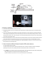
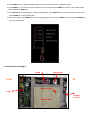
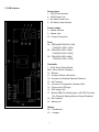
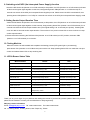
SF-1000R Security Smoke Generator (Wireless Control)
User Manual
Warning!
* Hot nozzle! Keep at least 50 cm distance from nozzle.
* The heater of the generator is extremely hot. Please be careful when the front cover is open.
* No user serviceable parts inside. Please contact with an authorized dealer when maintenance is required.
* Please disconnect power before changing fuse.
* Please operate only with adult supervision.
* Only Weiyang security specific smoke liquid should be used. Other fluid may damage the equipment or cause dangers to
human physical safety.
* Do not use without smoke liquid.
* For indoor use only. Please keep dry.
* Please clear smoke away from room after a smoke ejectment. Otherwise, residue might be caused.
Package
Before starting installation Weiyang security smoke generator, please make sure that you have all the following equipments:
● 1 × security smoke generator
● 1 × 500c.c. Smoke fluid bladder
● 1 × Mounting set (Hanging Bracket and Screws)
● 1 x Wireless 4-key controller
● 1 x Wireless PIR (Motion Detector)
1. Prior to installation:
Open packing carton and check whether smoke generator and all accessories are intact. Please check the technical
label in the back of machine and make sure to operate the unit at rated voltage and frequency.
2. Machine installation instruction:
Once plug in the unit, the build-in buzzer will keep beeping for 30seconds. Also, the orange LED light in the side of
machine will flash. (When smoke liquid bladder is not installed) It takes about 20 minutes for machine to complete
heat-up process. (The exact needed time depends on power offered and surrounding temperature.
3. Smoke liquid bladder installation and replacement:
● The 500c.c. smoke liquid is packed by a specific bladder and it is put inside of machine (upside of heater)
Please do plug in power before install and replace bladder. By doing this, the timer can be reset automatically and
the timer can record the operation time and warn Low Fluid Level correctly.
● Please release the bag clamp and take out the old bladder when replacing bladder.
● Please insert the needle (Fluid pipe connecter) into bladder completely (Note: needle should go into OUT position)
and then place bladder into the bladder chamber well. Make sure the neck of bladder reset the micro switch inside
the chamber, and screw the bag clamp firmly.
1
4. Function instruction
● This model can be controlled by wireless control only.
● The source of wireless control can be wireless PIR (motion detector), wireless window sensor, and wireless remote
controller…etc.
● This unit is a dual power model. Therefore, when the AC main power is cut-off, the power from UPS (Un-interrupted
Power Supply) can provide power to the PC board and pump of the unit to make it keep working. However, it can not
provide power to heater. Thus, if the main power is cut-off and the smoke machine is set off once, the smoke machine
can not offer second smoke output.
● When the smoke liquid is run out, the LED and buzzer will flash and beep to remind users (Please see below LED and
buzzer status table) and stop producing smoke (In order to protect pump and ensure a longer lifespan of pump)
※ Please place a whole new full smoke liquid bladder when replacing bladders. Otherwise, it will cause the timer record
wrong operation time and damage pump.
5. Action instruction: (Wireless Remote Controller & PIR, motion detector)
The 4-key wireless remote controller:
In order to avoid incorrect actions caused by unintentional touch, the buttons of wireless controller are designed
specifically hard to press. Thus, please press buttons hard and press at least 2 seconds per time.
1. Press AWAY key can make the machine enter guarding status. (LED green light flash slowly under guarding status)
Under guarding status, the wireless PIR (motion detector) starts to work.
※ Please remember to open the front cover of the PIR and switch on the PIR power.
2
2. Press HOME key can release guarding status or stop smoke output which is triggered by PIR.
3. Press PANIC key can force the smoke machine to eject smoke and press PANIC key again to stop smoke output
which is set off by PANIC key.
4. The UNLOCK key is the testing key. Under guarding status, press UNLOCK key can test the smoke machine and
press HOME key to stop smoking test.
5. After smoke output, press AWAY key can re-enter guarding status and press AWAY key and than press HOME key
can enter ready status.
6. Inner structure design:
PUMP
Thermostat
UP
DOWN
Smoke Outlet
PCB
Fluid Bag
Heater Block
3
Chamber
7. PCB Schema
Power input:
1‧UPS Power Neutral
2‧UPS Power Line
3‧AC Main Power Line
4‧AC Main Power Neutral
Power output:
5‧Heater Neutral
6‧Heater Line
23‧Pump Connection
Fuse:
24‧F800mA/250V(220V~240)
F1A/250V(100V~120V)
25‧F2A/250V(100V~120V)
F1A/250V(220V~240V)
26‧T5A/250V(220V~240V)
T7A/250V(100V~120V)
Terminals:
7‧Fluid Timer Reset Switch
8&9‧Micro Switch (Tamper)
10‧Buzzer
11‧Jumper (Switch off buzzer)
19‧Connect to Wireless Remote Receiver
13‧No Function
14‧Connect to Temperature Sensor Wire
15‧Three-color LED light
16‧DIP Switch 1&2
17‧Button PB2 (For Switching on / off UPS Function)
18‧Button PB1
(For Testing & Setting Smoke Output Duration)
20‧No Function
21‧Memory IC
Others:
22‧Transformer
12‧ Jumper
4
8. Switching on/off UPS (Un-interrupted Power Supply) function
Switch the DIP Switch #2 (Number 16 on PCB schema) to ON position, the LED (Number 15 on PCB schema) will start
to flash red and green lights together. At this time, keep pressing button PB2 (Number 17 on PCB schema) for 5
seconds can switch off the UPS (Un-interrupted Power Supplier) mode. Please note if the UPS is switched off, then
pressing button PB2 (Number 17 on PCB) for 5 seconds can switch on the UPS (Un-interrupted Power Supply) mode
9. Setting Smoke Output Duration Time
Switch the DIP Switch #2 (Number 16 on PCB schema) to ON position, the LED (Number 15 on PCB schema) will start
to flash red and green lights together. At this moment, keep pressing button PB1 (Number 18 on PCB schema) for 10
seconds can reset the smoke output duration time (The original setting is at 15 seconds per ejection). Pressing PB1
once can add 15 seconds smoke output duration. The maximum is to press 23 times PB1 to set a 6-minute non-stop
smoke output duration.
※ Please note when switching the DIP Switch #2 (Number 16 on PCB schema) to OFF position, the button PB 2
(Number 17 on PCB schema) is no function.
10. Testing Machine
When the machine is well installed and completes the heating process (LED green light on permanently),
press button PB 1 (Number 18 on PCB schema) can test the unit. Keep pressing button PB1 can make the unit eject
smoke and release button PB1 to stop smoking test.
11. LED & Buzzer Status Table
Machine Status
Buzzer
LED
Normal
No buzzer
Permanent green
Guarding
No buzzer
Green light flashes slowly
Machine Overheating
1 short beep every 5 sec.
Red flash twice every 2 sec.
Side Cover Opened
1 long beep every 1 min.
Red flash once every 2 sec.
UPS Power Cut
3 short beeps every 30 sec.
Red flash twice every 5 sec.
AC Power Cut
2 short beeps every 30 sec.
Red flash once every 5 sec.
Heater Fault
1 long beep every 10 sec.
Red flash rapidly
Fluid Level Empty
1 long and 1 short beep every 5 min.
Orange flash
Fluid Level Low
1 short beep every 5 min.
Permanent orange
Heating Process incomplete
Long beep for 30 sec. and then 3 short
Permanent red
beeps every 5 min.
DIP 2 switch to ON
No buzzer
Red and green flash together
Thank you very much again for your patience and reading this manual. If you have any further question about our products,
please do not hesitate to contact your local distributor or Weiyang directly.
Weiyang contact information
Email: [email protected] Tel: +886-2-2269-3323 Fax:+886-2-2269-3325
No. 13, Datong Street, Tucheng District, New Taipei City, Taiwan
5
NOTE
6