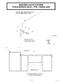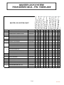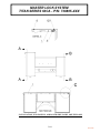
1
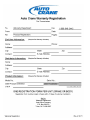
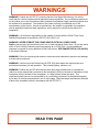
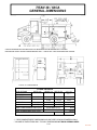
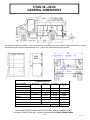
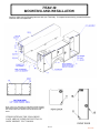
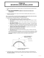
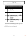
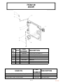
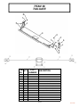
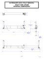
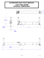
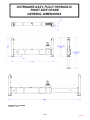
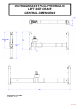
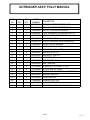
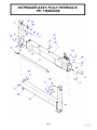
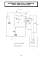
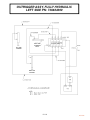
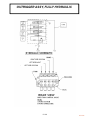
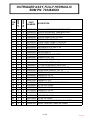
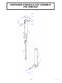
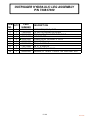
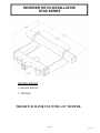
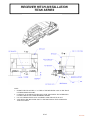
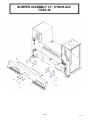
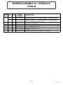
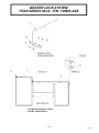
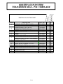
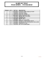
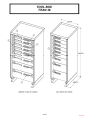
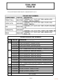
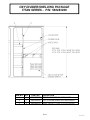
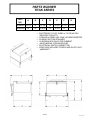
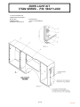
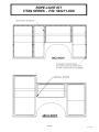
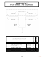
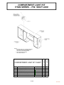
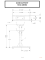
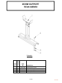
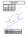
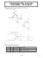
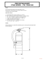
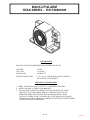
38 OWNERS MANUAL Serial No. __________________ Mailing Address: P.O. Box 580697 Tulsa, OK 74158-0697 Physical Address: 4707 N. Mingo Rd. Tulsa, OK 74117-5904 Phone 1-800-777-2760 Fax 1-888-848-5445 http://www.autocrane.com TITAN 38 OWNER’S MANUAL REVISION RECORD Revision Date Section(s) Or Page(s) Description of Change 3/18/2012 All New Manual 8/03/2012 8-6 Added items to ToolBox Service Part Numbers BOM 1/22/13 1-4 Revised General Dimensions on Rear View Notes: 1. The information contained in this manual is in effect at the time of this printing. It does not cover all instructions, configurations, accessories, etc. If you require additional information, please contact Auto Crane Company. 2. Auto Crane Company reserves the right to update this material without notice or obligation. NOTES WARNINGS WARNING! Federal law (49 CFR 571) requires that the Final Stage Manufacturer of a vehicle certify that the vehicle complies with all applicable federal regulations. Any modifications performed on the vehicle prior to the final state are also considered intermediate stage manufacturing and must be certified as to compliance. The installer of this crane and body is considered one of the manufacturers of the vehicle. As such a manufacturer, the installer is responsible for compliance with all applicable federal and state regulations, and is required to certify that the vehicle is in compliance. WARNING! It is the further responsibility of the installer to comply with the OSHA Truck Crane Stability Requirements as specified by 29 CFR 1910.180 (C) (1). WARNING! NEVER OPERATE THE CRANE NEAR ELECTRICAL POWER LINES! Death or serious injury will result from boom, line, or load contacting electric lines. Do not use crane within 10 feet (3.05m) of electric power lines carrying up to 50,000 volts. One-foot additional clearance is required for every additional 30,000 volts or less. SEE DANGER DECAL (P/N 040529) in this Owner's Manual. WARNING! Failure to correctly plumb and wire crane can cause inadvertent operation and damage to crane and/or personnel! WARNING! Vehicle must meet Federal law (49 CFR 393) which states the required parts and accessories necessary for safe operation. This includes lighting, reflectors, etc… WARNING! Federal law (49 CFR 568) requires each final-stage manufacturer to complete the vehicle in such a manner that it conforms to the standards in effect on the date of manufacture of the incomplete vehicle, the date of final completion, or a date between those two dates. This requirement shall, however, be superseded by any conflicting provisions of a standard that applies by its terms to vehicles manufactured in two or more stage. Each final-stage manufacturer shall affix a label to the completed vehicle in accordance with 49 CFR 567.5. READ THIS PAGE 02/14/12 TABLE OF CONTENTS TITAN 38 BODY TITAN BODY INTRODUCTION GENERAL DIMENSIONS MOUNTING AND INSTALLATION VEHICLE OPERATION AND PREPARATIONS TITAN 38 DOOR TITAN 38 TAILGATE OUTRIGGER, FULLY MANUAL, RIGHT SIDE DIMENSIONAL OUTRIGGER, FULLY MANUAL, LEFT SIDE DIMENSIONAL OUTRIGGER, FULLY HYDRAULIC, RIGHT SIDE DIMENSIONAL OUTRIGGER, FULLY HYDRAULIC, LEFT SIDE DIMENSIONAL OUTRIGGER SHIP KIT OUTRIGGER INSTALLATION OUTRIGGER ASSY, FULLY MANUAL OUTRIGGER ASSY, FULLY HYDRAULIC OUTRIGGER HYDRAULIC LEG ASSEMBLY RECEIVER HITCH INSTALLATION BUMPER INSTALLATION BUMPER ASSEMBLY 12" BUMPER ASSEMBLY 24" MASTER LOCK SYSTEM SHELF LOCATION SLIDE OUT TRAY TOOL BOX OXY/ACET ASSY OXY DIVIDER/SHELVING PACKAGE DROP WELL PARTS WASHER ROPE LIGHT KIT COMPARTMENT LIGHT KIT FLOOD LIGHT KIT BOOM SUPPORT BULKHEAD RESERVOIR AIR RECEIVER TANK 30 GALLON FIRE EXTINGUISHER BACK UP ALARM BODY PREVENTIVE MAINTENANCE 1‐1.0 1‐2.0 2‐1.0 3‐1.0 4‐1.0 4‐2.0 5‐1.0 5‐2.0 5‐3.0 5‐4.0 5‐5.0 5‐6.0 5‐7.0 5‐9.0 5‐15.0 6‐1.0 6‐4.0 6‐6.0 6‐8.0 7‐1.0 8‐1.0 8‐3.0 8‐5.0 9‐1.0 9‐2.0 9‐3.0 9‐4.0 10‐1.0 10‐4.0 11‐1.0 12‐1.0 13‐1.0 13‐2.0 14‐1.0 15‐1.0 16‐1.0 03/12/12 TITAN BODY INTRODUCTION Auto Crane products are designed to provide many years of safe, trouble-free, dependable service when properly used and maintained. To assist you in obtaining the best service from your crane and to avoid untimely crane and/or vehicle failure, this manual provides the following operating and service instructions. It is specifically recommended that all operating and service personnel consider this manual as mandatory material for reading and study before operating or servicing Auto Crane products. It is highly recommended that crane owners, equipment managers, and supervisors also read this manual. For your convenience the overall dimensions of the Titan are included on the General Dimension Drawing. Center of gravity and door openings are also shown. Remember, the body adds weight to the vehicle. Adding weight may change the driving and riding characteristics of the vehicle unless the appropriate overload spring(s) are installed on the truck. The payload of the vehicle is reduced by the weight of the body. The operator should exercise care when loading the vehicle. Distributing the payload on the vehicle evenly will greatly improve the driving and riding characteristics of the vehicle. Auto Crane will not assume responsibility or liability for any modifications or changes made to unit, or installation of component parts without authorization. Auto Crane maintains a strong distributor network and a knowledgeable Customer Service Department. In most cases, an equipment problem is solved via phone conversation with our customer service department. The customer service department also has the ability to bring a local distributor, a regional sales manager, or a factory serviceman into the solution of an equipment problem. If, through no fault of Auto Crane Company, it is necessary to send an experienced factory serviceman on a field service call the rates stated in the Auto Crane Distributor's Flat Rate Manual will apply. Auto Crane Company's extensive Research and Development Program allow our customers to use the best equipment on the market. Our Engineering Staff and our knowledgeable sales people are always available to our customers in solving crane and winch-type application problems. When in doubt, call the Auto Crane factory. Note: This manual should remain with the body at all times. DISTRIBUTOR ASSISTANCE: Auto Crane Company issues a limited warranty certificate with each unit sold. See last page for warranty. It has always been Auto Crane Company policy to handle all warranty claims we receive as promptly as possible. If a warranty claim involves discrepant material or workmanship, Auto Crane will take immediate corrective action. It is understandable that Auto Crane Company cannot assume responsibility of liability when it is obvious that our products have been abused, misused, overloaded or otherwise damaged by inexperienced persons trying to operate the equipment without reading the manual. Should you require any assistance not given in this manual, we recommend that you consult your nearest Auto Crane Distributor. Our distributors sell authorized parts and have service departments that can solve almost any needed repair. This manual does not cover all maintenance, operating, or repair instructions pertinent to all possible situations. If you require additional information, please contact the Auto Crane Company. The information contained in the manual is in effect at the time of this printing. Auto Crane Company reserves the right to update this material without notice or obligation. 1-1.0 03/12/12 NOTES TITAN 38 / 60CA GENERAL DIMENSIONS * CHECK CHASSIS BODY BUILDER BOOK FOR REQUIRED GAP BETWEEN BODY & CHASSIS **DEPARTURE ANGLE SHOWN FOR REFERENCE ONLY. ANGLE WILL VARY DEPENDING ON CHASSIS. TYPICAL ALL COMPARTMENTS TITAN 38 60CA DOOR OPENING WIDTH (W) HEIGHT (H) DEPTH (D) VOL. CU. FT.^ FRONT STD. 34 5/8 46 21 7/8 20.16 FRONT TALL 34 5/8 HORIZONTAL 44 25.31 11.98 17.43 INSIDE COMPARTMENT SIZES (STD) 57 3/4 21 7/8 21 1/2 21 7/8 46 21 7/8 TOTAL BODY CU. FT. INSIDE COMPARTMENT SIZES (TALL) TOTAL BODY CU. FT. SIZES/DEPTH REAR*** 29 15/16 WEIGHT 99.14 104.29 2685 LBS *** REAR COMPARTMENT DIMENSIONS/VOLUME ARE FOR NON CRANE BOX ONLY ^ VOLUME IS TAKEN FROM WALL TO WALL DIMENSIONS NOT DOOR OPENING SIZES 1-3.0 03/12/12 TITAN 38—84CA GENERAL DIMENSIONS * STANDARD GAP USING 84CA BODY. CHECK CHASSIS BODY BUILDER BOOK FOR REQUIRED GAP BETWEEN BODY & CHASSIS **DEPARTURE ANGLE SHOWN FOR REFERENCE ONLY. ANGLE WILL VARY DEPENDING ON CHASSIS. TITAN 38 84CA DOOR OPENING WIDTH (W) HEIGHT (H) DEPTH (D) VOL. CU. FT^. FRONT STD. 36 1/4 46 21 7/8 21.11 FRONT TALL 36 1/4 MID 22 1/4 26.5 12.96 11.98 17.43 INSIDE COMPARTMENT SIZES (STD) 57 3/4 21 7/8 46 21 7/8 21 1/2 21 7/8 46 21 7/8 TOTAL BODY CU. FT. INSIDE COMPARTMENT SIZES (TALL) TOTAL BODY CU. FT. SIZES/DEPTH HORIZONTAL REAR*** 44 29 15/16 WEIGHT 126.95 132.34 3330 LBS *** REAR COMPARTMENT DIMENSIONS/VOLUME ARE FOR NON CRANE BOX ONLY ^ VOLUME IS TAKEN FROM WALL TO WALL DIMENSIONS NOT DOOR OPENING SIZES 1-4.0 01/22/13 TITAN 38 MOUNTING AND INSTALLATION Check to make sure the following items are with your Titan body. If components are missing, contact AutoCrane Customer Service Department. NOTE: APPLY ATV SEALANT TO ONE END OF DOOR GASKET. PRESS BOTH ENDS TOGETHER AFTER INSTALLING. SMEAR ANY EXCESS SEALANT AROUND THE SEAM WHEN COMPLETE. ITEMS LISTED ON THE FOLLOWING PAGE ARE INCLUDED IN THE TITAN 38 BODY SHIP KIT. P/N 739408010 2-1.0 03/12/12 TITAN 38 MOUNTING AND INSTALLATION ITEM PART QTY DESCRIPTION NO. NUMBER 1 2 3 4 5 6 7 8 9 10 11 12 13 14 15 16 17 18 19 20 21 22 23 24 25 26 27 28 29 30 31 32 33 34 6 4 2 1 4 2 2 2 4 1 2 2 2 1 168in 12 12 32in 2 20 14 8 6 8 8 8 4 4 2 1 1 8 4 4 739408005 739408003 739408004 560106003 560449000 560450000 560451000 560452000 560453000 752221000 752222000 738706000 739408002 738597001 750740000 750737000 750738000 750736000 560510000 754028000 020200000 015900000 005901000 006020000 019600000 015400000 560540000 739209000 760629000 750980000 560114000 560525000 739408008 739408007 GROMMET, LIGHT OVAL LIGHT, STOP/TURN/TAIL OVAL LIGHT, BACK-UP OVAL HARNESS, BODY WIRING 3-LIGHT BRACKET MOUNTING CLEARANCE MARKER AMBER CLEARANCE MARKER RED REFLECTOR AMBER REFLECTOR RED PANEL LOUVER PANEL BLANK F/ MID VENT OPENING COVER FUEL LINE GUARD, ROCK ALUMINUM TITAN FENDERETTE INSTL KIT TITAN 38 GASKET FL 1in X 1/8 TIE WRAP PUSH-IN STICK-ON, CABLE TIE MOUNT LOOM, CONVOLUTED, 7/16 ID DECAL "TITAN" RIVET POP 3/16 DIA X 1/4 - 3/8 GRIP SS WASHER SP LK 1/4 NUT HX 1/4-20UNC SS SCREW HX HD 1/4-20UNC X 1/2 LG SCREW PN HD #6-32UNC X 1LG WASHER SP LK #6 NUT HX #6-32UNC GROMMET, NYLON CAPLUG, 1" DIA HANDLE, GRAB PLASTIC BLACK W/GRIP LAMP, LICENCE W/BRACKET GASKET, DOOR 2003 T-HANDLE ASSY SCREW, FLAT 1/4-20UNC 1-3/8LG SCREW, FLAT 1/4-20UNC 1-3/4LG 2-2.0 03/12/12 TITAN 38 MOUNTING AND INSTALLATION !! WARNINGS !! DO NOT WELD TO TRUCK FRAME. REFER TO BODY-BUILDERS MANUAL FOR FUTHER INFORMATION INSTALLATION INSTRUCTIONS BELOW ARE COMMON MOUNTING PRACTICES, ALWAYS REFER TO CHASSIS BODY-BUILDERS MANUAL FOR ACCEPTABLE MOUNTING OPTIONS CUTTING AFTER-FRAME MAY BE REQUIRED. REFER TO CHASSIS BODY-BUILDERS MANUAL FOR PROPER CUTTING PROCEDURE. MINIMUM CHASSIS REQUIREMENTS 11,400 LBS GVWR 34” FRAME WIDTH HEAVY-DUTY REINFORCED FRAME ALL DIMENSIONS SHOWN ARE IN INCHES. MOUNTING INSTRUCTIONS: AVAILABLE MOUNTING KIT—560580000 INCLUDES HARDWARE & SHEAR PLATES 1. Pick up body using a 4-point choke chain rated for the body weight shown in Gen. Dimension page. Use the tie down locations in bed for lifting points. 2. Center body along the width of the chassis and center the wheel well with the tires. NOTE: MAKE SURE YOU HAVE ENOUGH CLEARANCE BETWEEN BODY AND CHASSIS CAB PER THE MANUFACTURERS REQUIREMENTS. 3. Locate the shear plates as shown in the above diagram. Drill (2) 21/32Ø holes into each shear plate and chassis frame. NOTE: LOCATE HOLE FOR BOLT SO THAT THE BOLT, WASHER, AND NUT WILL NOT INTERFERE WITH ANY CHASSIS COMPONENTS. LOCATIONS OF SHEAR PLATES SHOWN ABOVE ARE PREFERRED LOCATIONS. THEY MAY NEED TO BE MOVED TO ACCOMMODATE COMPONENTS ON THE CHASSIS RAILS. 2-3.0 03/12/12 TITAN 38 MOUNTING AND INSTALLATION 4. Using the pre-drilled holes in the outrigger support, drill (3)21/32”Ø holes into chassis rail per side. 5. Weld shear plates to the body frame. NOTE: FOLLOW CHASSIS RECOMMENDATIONS WHEN WELDING BODY COMPONENTS. 6. Bolt Body to Chassis Frame using 5/8” UNC Grade 8 Hardware (Bolt, Washer, Nut, Etc…) Torque to 180 Ft-Lbs Note: If you would like to mount the body using another method, please refer to the chassis manufacturer’s body builder guide or the NTEA handbook. 7. Install Fenderettes (Supplied) to the body: (Reference figure below) a. Wipe mounting surface with clean cloth to remove any dirt or oils. b. Locate Fenderette to sidepack, aligning the bottom edges and centering it on fender well opening. c. Draw lines on fender with oil pencil or other erasable marker to assist with alignment when adhesive is applied. d. Apply adhesive to fenderette flange per instructions on cartridge. 1/8” bead in center of flange is recommended. The nozzle does not need to be cut to provide 1/8” bead. e. Use lines from step 3 to locate fenderette to sidepack, aligning the bottom edges and centering it on the fender well opening as before. f. Using wide surface area clamps, clamp fenderette into place to insure full contact between the fenderette flange and the sidepack. g. Remove any excess adhesive from outer edges. h. Allow adhesive to cure 3 to 4 hours before removing clamps. Adhesive will be fully cured in 8 to 24 hours. (If you would like to paint the fenderette, you must use the following components. Surface must be cleaned with DuPont #3919S Prep-Sol or equivalent, Primed with Polypropylene primer (Ditzler DPX800 or equivalent), and use a flex additive (Ditzler DX369 or equivalent). 8. Install wiring, lights, and reflectors onto body. Reference schematic on following page for wiring detail. Reference view at beginning of Mounting and Installation section for location of remaining components. 2-4.0 03/12/12 TITAN 38 MOUNTING AND INSTALLATION 2-5.0 03/12/12 TITAN 38 MOUNTING AND INSTALLATION WIRE # COLOR DESCRIPTION LABEL 1 GREEN STOP/TURN SIGNAL RIGHT SIDE 2 WHITE GROUND 3 YELLOW STOP/TURN SIGNAL LEFT SIDE 4 BLUE BACK-UP SIGNAL 5 BLACK TAIL LIGHT SIGNAL 6 RED OPTIONAL HALOGEN SUPPLY WIRE 7 BLACK OPTIONAL REAR WORK LIGHT LEFT SIDE WRK LT LFT 8 BLACK OPTIONAL REAR WORK LIGHT RIGHT SIDE WRK LT RT 9 BLACK OPTIONAL LIGHTING RIGHT SIDE OPTIONAL LIGHTING 10 BLACK OPTIONAL LIGHTING LEFT SIDE OPTIONAL LIGHTING 11 WHITE INTERIOR COMPARTMENT LIGHT LEFT SIDE (OPTIONAL) 12 BLACK INTERIOR COMPARTMENT LIGHT LEFT SIDE (OPTIONAL) 13 WHITE INTERIOR COMPARTMENT LIGHT RIGHT SIDE (OPTIONAL) 14 BLACK INTERIOR COMPARTMENT LIGHT RIGHT SIDE (OPTIONAL) HALOGEN 8. Install all accessories per their installation procedures. If unit has a hydraulic outrigger, you must follow the procedure shown on the following page to set the outrigger relief valve. 9. Verify final truck configuration meets all applicable federal guidelines. Reference 49CFR571.109 10. Read operating section of manual before operating the unit. 2-6.0 03/12/12 TITAN 38 MOUNTING AND INSTALLATION OUTRIGGER RELIEF VALVE SETTING INSTRUCTIONS For hydraulic powered outrigger control valves provided by AutoCrane AutoCrane hydraulic powered outriggers utilize a control valve which contain an integral hydraulic relief valve that is preset at the factory. This preset is NOT the final setting and must be adjusted to account for hydraulic system backpressure once the installation is complete. The adjustment is straight forward are requires basic hand tools, thermometer or means to measure hydraulic oil temperature, and a hydraulic pressure gauge with a minimum rating of 5,000 psi and hydraulic fittings necessary to install the gauge in-line with the incoming pressure line to the outrigger control valve body. Follow the procedure below to make the final adjustments to this relief valve. 1. The outrigger hydraulic relief valve should be adjusted to 200 psi above the crane hydraulic relief valve. Please consult the appropriate owner’s manual for this setting or contact the crane manufacturer for this value. WARNING! Under no circumstances should this relief valve setting exceed any of the hydraulic system components ratings or limitations as component damage or personal injury may result. 2. Install the hydraulic pressure gauge in-line with the incoming pressure line to the outrigger control valve body. 3. With all personnel clear of the vehicle, start the engine and engage the vehicle PTO. Let the hydraulic oil w arm until it reaches 100°F. 4. While watching the hydraulic pressure gauge, activate a hydraulic outrigger function to deadhead the hydraulic system. Read the gauge value quickly and do not hold the function into the deadhead position. 5. Using the hand hold, back off the lock not on the hydraulic relief valve and make small rotation adjustments (1/2 turn) to the relief valve stem. 6. Repeat step 4 to check if this adjustment meets the system requirements. If not, then repaeat Step 5 and Step 4 until correct. 7. Tighten the lock nut on the hydraulic relief valve. 8. Remove the hydraulic pressure gauge and fittings and re-attach the pressure supply line to the hydraulic valve body. 2-7.0 03/12/12 TITAN 38 VEHICLE OPERATION & PREPARATIONS IMPORTANT—READ FIRST!! VEHICLE PREPARATION FOR OUTRIGGER AND CRANE OPERATION 1. Park vehicle within crane operating distance from object that is to be lifted. Notes: Make sure there are no obstructions preventing safe handling of load during crane operation. Verify that no obstructions will prevent the full extension of the outrigger legs on both sides of vehicle. Regardless of load to be lifted the outriggers should always be fully extended to keep vehicle stable. Grade shall not exceed 1° of level. Level truck with blocks if grade exceeds 1° of level. 2. ALWAYS set the vehicle emergency brake before beginning crane operations. 3. Use wheel chocks on the front wheels of vehicle. INSPECT OUTRIGGERS BEFORE USE 1. Visually inspect outrigger before use making sure the outrigger is in good working order. 2. Replace or repair any warn or damaged parts before outrigger operation. 3. Check for and repair leaks on hydraulic units if they occur. MANUAL OUTRIGGER OPERATION 1. Un-hook the sling from around the outrigger leg. 2. Extend outrigger slide from stowed position by releasing pull pin and extending the outrigger slides fully. 3. Make sure the slide is fully extended and locked into position with pull pin. 4. Lower both outrigger legs until they contact the ground then extend another inch to insure good ground contact. Notes: Use blocks under pads to increase surface area if required for stability on soft ground. DO NOT LIFT TRUCK WHEELS WITH OUTRIGGERS. The outriggers are intended for vehicle stability during lifting operations not for complete vehicle support. MANUAL OUTRIGGER STOWING PROCEDURE 5. 6. 7. 8. Fully retract vertical legs to stowed position. Retract outrigger slide from extended position by releasing pull pin and pushing slides in fully. Make sure the slide is fully retracted and locked into position with pull pin. Make sure the sling is secured in place around the outrigger leg. 3-1.0 03/12/12 TITAN 38 VEHICLE OPERATION & PREPARATIONS HYDRAULIC OUTRIGGER OPERATION 1. Divert hydraulic flow from control valve to outrigger operations. 2. Use the hydraulic control valve to extend outrigger slide from stowed position to the fully extended position. 3. Make sure the slide is fully extended. 4. Lower both outrigger legs until they contact the ground then extend another inch to insure good ground contact. Notes: Use blocks under pads to increase surface area if required for stability on soft ground DO NOT LIFT TRUCK WHEELS WITH OUTRIGGERS. The outriggers are intended for vehicle stability during lifting operations not for complete vehicle support. HYDRAULIC OUTRIGGER STOWING PROCEDURE 5. 6. 7. 8. Fully retract vertical legs in stowed position. Retract outrigger slide from extended to the fully retracted position. Make sure the slide is fully retracted in the stowed position. Make sure the sling is secured in place around the outrigger leg. 3-2.0 03/12/12 TITAN 38 DOOR ITEM PART QTY DESCRIPTION NO. NUMBER 1 2 3 4 5 6 7 2 2 2 1 2 4 1 016801000 020300000 760535002 760535001 *SEE CHART 002609000 560525000 NUT HX NYLK 5/16‐18UNC CP WASHER FL 1/4 CP BALL STUD THREADED 5/16‐18 DOOR PROP (GAS) DOOR ROD SCREW RD HD #10UNF X 5/8 CP GR3 T‐HANDLE PART DESCRIPTION NUMBER USED ON USED ON ALL 52" COMPARTMENT DOORS, UPPER/LOWER USED ON 58" COMPARTMENT DOORS, UPPER USED ON HORZ. COMP. UPPER/LOWER 4-1.0 560415000 560417000 560416000 DOOR ROD STD DOOR ROD TALL DOOR ROD HORIZ 03/12/12 TITAN 38 TAILGATE ITEM PART QTY DESCRIPTION NO. NUMBER 1 2 3 4 5 6 7 8 9 10 11 12 13 14 15 1 1 1 2 2 2 2 2 4 4 1 2 2 12 1 560085000 560088000 560081000 560090000 560091000 736738000 021403000 016801000 010201000 177010000 560093000 560094000 560096000 754028000 560098000 MTG BRKT WDMT LH MTG BRKT WDMT RH TAILGATE SUB ASSY CABLE ASSY TAILGATE SCREW SHO SET 1/2 X 3/8 TAILGATE BUSHING WASHER, FLAT‐HARDENED 3/8 NUT HX NYLK 5/16‐18UNC CP SCREW HX HD 1/2UNC X 1 1/2 GR5 NUT HX 1/2 NCCP LATCH ASSY TAILGATE LATCH ROD 3/8 RIVET 3/16 POP .251‐.375 GRIP SS GASKET 4-2.0 03/12/12 NOTES OUTRIGGER ASSY, FULLY MANUAL RIGHT SIDE CRANE GENERAL DIMENSIONS 5-1.0 03/12/12 OUTRIGGER ASSY, FULLY MANUAL LEFT SIDE CRANE GENERAL DIMENSIONS 5-2.0 03/12/12 OUTRIGGER ASSY, FULLY HYDRAULIC RIGHT SIDE CRANE GENERAL DIMENSIONS EXTENSION CYLINDER STROKE = 54.00 5-3.0 03/12/12 OUTRIGGER ASSY, FULLY HYDRAULIC LEFT SIDE CRANE GENERAL DIMENSIONS EXTENSION CYLINDER STROKE = 54.00 5-4.0 03/12/12 TITAN 38 OUTRIGGER SHIP KIT OUTRIGGER SHIP KIT 738645000 ITEM NO. QTY PART NUMBER DESCRIPTION 1 2 2 2 738563001 738669000 TITAN 38 BUMPER SUPPORT F/HITCH BAR RT HR 1/4 X 7 X 5.75 LG 5-5.0 03/12/12 TITAN 38 OUTRIGGER INSTALLATION 5-6.0 03/12/12 OUTRIGGER ASSY, FULLY MANUAL RIGHT SIDE CRANE PN: 738896000 LEFT SIDE CRANE PN: 738897000 5-7.0 03/12/12 OUTRIGGER ASSY, FULLY MANUAL ITEM NO. 1 1 2 LS QTY 0 1 1 RS QTY 1 0 1 3 4 5 1 1 4 1 1 4 738898000 TITAN 38 MANUAL OUTRIGGER LEG, LS 738888000 TITAN 38 SLIDE ASSY RS MANUAL 407277000 PAD BOOM 1.5 O.D. 6 7 8 1 1 2 1 1 2 760390110 3/4 PULL PIN WELD W/ MTG BRACKET 738606000 DECAL LAYOUT MANUAL 005901000 SCREW HX HD 1/4-20UNC X 1/2 LG 9 10 11 3 2 2 3 2 2 008701000 SCW HX 3/8 UNC X 1 GR5 020200000 WASHER SP LK 1/4 020400000 WASHER FL SAE 1/4 12 13 14 4 4 1 4 4 1 021200000 WASHER FL 3/8 021500000 WASHER, SP LK 1/2 002393000 ZERK, GREASE 15 16 17 2 4 4 2 4 4 372218000 SCREW SET 1/2-13UNC X 3 LG 372219000 NUT, HX JAM 1/2-13UNC 738647000 SCREW HX HD 1/2-13UNC X 1 1/4 LG GR8 18 19 20 2 1 1 2 1 1 240234000 BEARING, NEEDLE 372216000 COVER ROLLER 738682000 DOUBLER PULL PIN 21 22 1 1 1 1 772067000 SLING, OUTRIGGER 460177160 WEAR PAD, 5.13X3X.25, BOSS 1X3 PART NUMBER 738602000 738602001 738645000 DESCRIPTION TITAN 38 OUTRIGGER TUBE WELD TITAN 38 OUTRIGGER TUBE WELD SHIP KIT TITAN 38 OUTRIGGER 5-8.0 03/12/12 OUTRIGGER ASSY, FULLY HYDRAULIC PN: 73848XXXX 5-9.0 03/12/12 OUTRIGGER ASSY, FULLY HYDRAULIC RIGHT SIDE PN: 738483000 812026269 RIGHT SIDE EXTENSION IN/OUT LEFT SIDE UP/DOWN RIGHT SIDE UP/DOWN 812026269 5-10.0 03/12/12 OUTRIGGER ASSY, FULLY HYDRAULIC LEFT SIDE PN: 738484000 LEFT SIDE UP/DOWN RIGHT SIDE EXTENSION IN/OUT RIGHT SIDE UP/DOWN 5-11.0 03/12/12 OUTRIGGER ASSY, FULLY HYDRAULIC RIGHT SIDE UP/DOWN LEFT SIDE IN/OUT LEFT SIDE UP/DOWN 5-12.0 03/12/12 ITEM NO. LS-4000 RS-3000 OUTRIGGER ASSY, FULLY HYDRAULIC BOM PN: 73848XXXX 1 1 2 2 3 4 4 5 6 7 8 9 10 10 11 11 12 13 14 15 16 17 18 19 20 21 22 23 24 25 0 1 0 1 0 0 1 1 4 1 3 1 0 1 0 1 18 3 3 3 5 3 2 4 3 7 4 3 4 4 1 0 1 0 1 1 0 1 4 1 3 1 1 0 1 0 18 3 3 3 5 3 2 4 3 7 4 3 4 4 PART DESCRIPTION NUMBER 738483100 738484100 738483220 738484220 738837000 560244000 560244001 366353000 407277000 738483300 407216000 738682000 738644000 738644001 738483001 738484001 374086000 005401000 020200000 020400000 020901000 811029000 016500000 017701000 021100000 021200000 021500000 330372000 738642000 480024000* TITAN 38 OUTRIGGER TUBE WELD HYD TITAN 38 OUTRIGGER TUBE WELD SSC TITAN 38 SLIDE ASSY CS HYD TITAN 38 SLIDE ASSY SS (HYD) TITAN 38 HYD LEG ASSY COVER, DIRECTIONAL CTR VALVE COVER, DIRECT CTR VALVE S/S PAD WEAR 5.25 X 2.63 X .38 PAD BOOM 1.5 O.D. CYL HYD IN/OUT HOSE RETAINER, 4.75 WIDE DOUBLER PULL PIN DECAL LAYOUT HYD DECAL LAYOUT SSC (HYD) KIT, HYD OUTRIGGER (FULLY HYD) KIT, HYD OUTRIGGER SSC (FULLY HYD) NYLON HOSE SLEEVE, 1.81" ID SCREW HX HD 1/4-20UNC X 5/8 LG CP WASHER SP LK 1/4 WASHER FL SAE 1/4 WASHER FL 5/16 SCREW HX HD 5/16-18UNC X 2 1/2 LG NUT HX 5/16-18UNC NUT HX 1/2-13UNC WASHER SP LK 3/8 WASHER FL 3/8 WASHER, SP LK 1/2 NUT HX 3/8-16UNC SCREW HX HD 1/2-13UNC X 1 3/4 LG GR8 MOUNT PENDANT CABLE RETAINER 5-13.0 03/12/12 ITEM NO. LS-4000 RS-3000 OUTRIGGER ASSY, FULLY HYDRAULIC BOM PN 73848XXXX PART NUMBER 26 4 4 008400000 SCREW HX HD 3/8-16UNC X 3/4 LG GR 5 27 3 3 330645000* FITTING 90 6-SAE/6-JIC LONG 28 29 30 3 4 2 3 4 2 241175000* 200876000* 560203000* FITTING 90 6-SAE/6-JIC FITTING 6 SAE/6 JIC STRAIGHT FITTING 90 6-SAE/6-JIC RESTRICTED 31 1 1 812037100* 32 33 34 35 36 37 1 1 1 1 1 1 1 1 1 1 1 1 812037091* 812037269* 812037271* 812026089* 812026096* 560145010 38 39 40 41 42 43 44 45 46 47 48 1 1 1 1 2 1 3 3 6 2 1 1 1 1 1 2 1 3 3 6 2 1 738058010 738058020 738058006 738058007 418073000 760229000 772046006 772042000 772043000 460177160 738645000 HOSE ASSY, -6 JICF/ -6 90 DEG ELL, -4 HOSE x 100" LG HOSE ASSY, -6 JICF/ -6 90 DEG ELL, -4 HOSE x 91" HOSE ASSY, -6 JICF/ -6 90 DEG ELL, -4 HOSE x 269" HOSE ASSY, -6 JICF/ -6 90 DEG ELL, -4 HOSE x 271" HOSE ASSY, -6JICF/-6JICF x -4 HOSE HOSE ASSY, -6JIC/-6JICF x -4 HOSE CONTROL VALVE SUB-ASSY, 4 SECTION WELDMENT-LONG ANCHOR CYLINDER BRACKET DESCRIPTION WELDMENT-SHORT ANCHOR CYLINDER BRACKET CAPSCREW-12/-13UNC X 3 GR8 CAPSCREW-12/-13UNC X 4, GR8 NUT HX 1/2-13UNC TRIM EDGE, 5/16 SPIRAL HOSE WRAP, 1/2", 6" LONG RUBBER STRIP, 1 X 8 X .06 ZIP TIE STRAP, 12 IN, NYLON, BLACK WEAR PAD, 5.13X3X.25, BOSS 1X3 SHIP KIT TITAN 38 OUTRIGGER NOTE: PART NUMBERS WITH AN ASTERISK ARE PART OF A KIT. 5-14.0 03/12/12 OUTRIGGER HYDRAULIC LEG ASSEMBLY P/N 738837000 5-15.0 03/12/12 OUTRIGGER HYDRAULIC LEG ASSEMBLY P/N 738837000 ITEM QTY NO. 1 2 3 4 5 6 7 8 9 10 1 1 1 1 4 4 1 1 4 2 PART NUMBER DESCRIPTION 738880000 738834000 738839000 725945000 005901000 020200000 738732000 738731000 738734000 560562000 TUBE INNER (WELD) LS/RS CYL HYD OUTRIGGER UP/DOWN TITAN 38 HYD LEG OUTER TUBE WELD CAP TUBE TOP SCREW HX HD 1/4-20UNC X 1/2 LG WASHER SP LK 1/4 PIN 1n X 4.063 LG PIN 1n X 4.563 LG RING RETAINING 5100-100 WASHER, FL 1.03ID x 1.75OD x .156 THICK ZINC YELL 5-16.0 03/12/12 RECEIVER HITCH INSTALLATION TITAN SERIES SPECIFICATIONS: 12,000 LBS RATING 2” OPENING THIS HITCH IS FOR USE WITH A 20” BUMPER. 6-1.0 03/12/12 RECEIVER HITCH INSTALLATION TITAN SERIES SPECIFICATIONS: 12,000 LBS RATING 2” OPENING THIS HITCH IS FOR USE WITH A 12” BUMPER. 6-2.0 03/12/12 RECEIVER HITCH INSTALLATION TITAN SERIES NOTE: 1. INSERT THE END OF THE 3 1/2" TUBE OF THE RECEIVER ASSY IN THE HOLE OF THE BUMPER SUPPORT. 2. CONTINUE TO SLIDE RECEIVER ASSY OVER AND INSERT THE OTHER END OF THE TUBE IN THE OTHER BUMPER SUPPORT. 3. LOCATE THE RECEIVER ASSY AS SHOWN AND WELD INTO PLACE. 4. ALSO WELD THE RECEIVER ASSY TO THE BOTTOM OF THE OUTRIGGER TUBE AS SHOWN. 6-3.0 03/12/12 TITAN 38 BUMPER INSTALLATION 6-4.0 03/12/12 BUMPER ASSEMBLY 12”, HYDRAULIC TITAN 38 6-5.0 03/12/12 BUMPER ASSEMBLY 12”, HYDRAULIC TITAN 38 ITEM LSC RSC NO. 1 1 2 3 4 5 6 0 1 4 4 3 8 8 1 0 4 4 3 8 8 PART NUMBER 738750000 738751000 766141000 750913000 560105000 021500000 010201000 DESCRIPTION BUMPER ASSY 12 in RECEIVER, TITAN 38 RSC BUMPER ASSY 12 IN RECEIVER, TITAN 38 LSC DECAL, SAFETY SURFACE BUMPER ADAPTER LIGHT MARKER LED 2" WASHER, SP LK 1/2 SCREW HX HD 1/2-13UNC x 1 1/2 LG 6-6.0 03/12/12 BUMPER ASSEMBLY 20”, HYDRAULIC TITAN 38 6-7.0 BUMPER ASSEMBLY 20”, HYDRAULIC TITAN 38 ITEM PART LSC RSC DESCRIPTION NO. NUMBER 1 1 2 3 4 5 6 1 0 5 4 3 8 8 0 1 5 4 3 8 8 738753000 738752000 766141000 750913000 560105000 021500000 010201000 BUMPER ASSY 20 in RECEIVER, TITAN 38 LSC BUMPER ASSY 20 in RECEIVER, TITAN 38 RSC DECAL, SAFETY SURFACE BUMPER ADAPTER LIGHT MARKER LED 2" WASHER, SP LK 1/2 SCREW HX HD 1/2-13UNC x 1 1/2 LG 6-8.0 MASTER LOCK SYSTEM TITAN SERIES 84CA - P/N: 738695-XXX INSTALLATION INTO BOTH LS AND RS STD SIDE PACKS ARE THE SAME 7-1.0 03/12/12 MASTER LOCK SYSTEM TITAN SERIES 84CA - P/N: 738695-XXX RIGHT SIDE SHOWN 7-2.0 03/12/12 DESCRIPTION ITEM NO. 1 MASTER LOCK GUIDE 2 MASTERLOCK LOCKING PLATE 3 4 PART NO. 560119000 S S TD 73 8695 -008 R TAL L 73 8695 -007 LS DBL TALL 73 8695 -006 LS S DBL TAL L 73 8695 -005 R STD 73 8695 -004 LS TD 73 8695 -003 S TALL S/LS TALL 73 8695 -002 LS 73 8695 -000 R MASTER LOCK SYSTEM CHART 73 8695 -001 R S TALL MASTER LOCK SYSTEM TITAN SERIES 84CA - P/N: 738695-XXX QTY. QTY. QTY. QTY. QTY. QTY. QTY. QTY. QTY. 3 2 3 4 2 3 3 1 2 560121001 2 2 2 SPACER, PUSH ROD 760559000 1 2 1 PUSH BAR LONG LS 739190000 1 2 1 1 2 2 1 1 1 1 1 1 1 PUSH BAR LONG RS 739190002 1 1 5 SPRING 736730000 2 2 2 2 1 2 2 1 1 6 MASTER LOCK MOUNT 560122000 2 2 2 2 1 2 2 1 1 PUSH BAR FRONT TALL RS 739193000 1 1 PUSH BAR FRONT TALL LS 739193002 PUSH BAR FRONT DBL TALL 739195000 PUSH BAR SHORT LS 739191000 PUSH BAR SHORT RS 739191002 PUSH BAR SHORT DBL TALL RS 739192000 PUSH BAR SHORT DBL TALL LS 739192002 7 8 1 1 1 1 1 1 1 1 1 1 1 1 1 1 9 SCREW CARRIAGE 3/8-16UNC X 1 LG 560138000 4 4 4 4 2 4 4 2 2 10 WASHER SP LK 3/8 021100000 4 4 4 4 2 4 4 2 2 11 NUT HX 3/8-16UNC 330372000 4 4 4 4 2 4 4 2 2 12 SCREW HX HD 1/4-20UNC X 5/8 LG CP 005401000 1 1 2 1 1 1 1 1 13 NUT HX NYLK 1/4-20UNC 016300000 1 1 2 1 5 5 2 1 14 WASHER FL 1/4 020300000 2 4 2 4 4 2 15 SCREW HX HD 1/4-20UNC X 1 LG 005604000 2 4 2 4 4 2 PUSH BAR MID DBL TALL RS 739194000 PUSH BAR MID DBL TALL LS 739194002 16 7-3.0 1 1 03/12/12 NOTES 7-4.0 MASTER LOCK SYSTEM TITAN SERIES 60CA - P/N: 738805-XXX INSTALLATION INTO BOTH LS AND RS STD SIDE PACKS ARE THE SAME 7-5.0 03/12/12 MASTER LOCK SYSTEM TITAN SERIES 60CA - P/N: 738805-XXX PUSH ROD INSTALLATION RIGHT SIDE SHOWN 7-6.0 03/12/12 ITEM NO. 1 2 3 4 5 6 7 8 9 10 11 12 13 14 15 DESCRIPTION PUSH BAR LONG RS, TITAN 38/60CA PUSH BAR LONG LS, TITAN 38/60CA PUSH BAR SHORT DBL TALL RS PUSH BAR SHORT DBL TALL LS MASTERLOCK LOCKING PLATE MASTER LOCK MOUNT SPRING MASTER LOCK GUIDE PUSH BAR FRONT RS TALL, TITAN 38/60CA PUSH BAR FRONT LS TALL, TITAN 38/60CA SPACER, PUSH ROD WASHER FL 1/4 SCREW HX HD 1/4-20UNC X 1 LG CP NUT HX NYLK 1/4-20UNC SCREW HX HD 1/4-20UNC X 5/8 LG CP SCREW CARRIAGE 3/8-16UNC X 1 LG WASHER SP LK 3/8 NUT HX 3/8-16UNC 7-7.0 -00 1 RS TAL L MASTER LOCK SYSTEM CHART -00 0 STD MASTER LOCK SYSTEM TITAN SERIES 60CA - P/N: 738805-XXX PART NO. QTY. QTY. 739197000 1 739197002 1 1 739192000 1 739192002 560121001 2 2 560122000 2 2 736730000 2 2 560119000 2 2 739196000 1 739196002 760559000 1 020300000 2 005604000 2 016300000 2 3 005401000 2 1 560138000 4 4 021100000 4 4 330372000 4 4 NOTES 7-8.0 SHELF LOCATION TITAN SERIES 738830-XXX LEFT SIDE RIGHT SIDE 8-1.0 03/12/12 * ** 002 003 004 005 006 007 008 PART NO. DESCRIPTION 750798000 SHELF STRIP SUPPORT 18" 750799000 SHELF STRIP SUPPORT 36" 340196000 TBG SQ 2 X .083W X 17 750804000 BRKT SHELF 560227000 TBG SQ STL 2 1/2 X .120W X 36 750807000 CHAIN HOOK ASS'Y 738825000 SHELF FRONT COMP 738741000 SHELF MID TITAN 38 738831000 SHELF HORIZ (PLASTIC DIVIDERS) 560481001 DIVIDER, SHELF TALL (PLASTIC) 560480001 DIVIDER, SHELF SHORT (PLASTIC) 738832002 SHELF REAR (PLASTIC DIVIDERS) 738794000 SHELF FRONT COMP FRONT COMP. SHELF 60CA LEFT OR RIGHT ONLY ITEM NOT SHOWN 001 ITEM 1 2 3 4 **5 6 *7 8 9 10 11 12 *13 000 SHELF LOCATION TITAN SERIES 738830-XXX QTY 8 12 4 4 2 1 2 6 2 10 13 3 QTY 4 QTY QTY QTY QTY QTY QTY 4 QTY 8 4 4 4 2 1 4 4 2 2 2 2 2 1 1 3 1 10 1 10 3 3 1 8-2.0 2 10 13 3 2 03/12/12 SLIDE OUT TRAY TITAN SERIES - P/N 560238000 8-3.0 03/12/12 SLIDE OUT TRAY TITAN SERIES - P/N 560238000 8-4.0 03/12/12 TOOL BOX TITAN 38 8-5.0 03/12/12 TOOL BOX TITAN 38 TITAN LEFT/RIGHT SIDE FRONT COMPARTMENT ONLY TOOLBOX SERVICE PART NUMBERS ITEM PART NO. 1 560330000 560330003 560330005 2 560330006 560332008 560332000 560332010 3 560332011 560322012 560332003 560332005 4 560332006 560332008 5 560331000 * 560333000 * 560336000 * 560335000 * 560334000 * DESCRIPTION BRUSHED HANDL W/O LOGO 8" BAR FOR HANDLE, TOOLBOX (24"W) 10" BAR FOR HANDLE, TOOLBOX (28"W) 11" BAR FOR HANDLE, TOOLBOX (30"W) 13 5/8" THUMB RELEASE BAR, W/O HANDLE, TOOLBOX (37"W) LATCH, TOOLBOX (14" WIDE UNIT WIDTH) LATCH, TOOLBOX (15‐1/2" WIDE UNIT WIDTH) LATCH, TOOLBOX (16" WIDE UNIT WIDTH) LATCH, TOOLBOX (20" WIDE UNIT WIDTH) 7 1/8" THUMB RELEASE BAR, W/O HANDLE, TOOLBOX (24"W) 9 1/8" THUMB RELEASE BAR, W/O HANDLE, TOOLBOX (28"W) 10 1/8" THUMB RELEASE BAR, W/O HANDLE, TOOLBOX (30"W) 13 5/8" THUMB RELEASE BAR, W/O HANDLE, TOOLBOX (37"W) LATCH BOLT HEAVY DUTY DRAWER SLIDES 16" DIVIDER TOOLBOX 7"HIGH X 16"DEEP DIVIDER TOOLBOX 5"HIGH X 16"DEEP DIVIDER, 3" HIGH X 16" DEEP NOT SHOWN 8-6.0 03/12/12 OXY/ACET ASSY TITAN SERIES - P/N: 736230000 ITEM NO. 1 2 3 4 5 6 7 QTY. PART NO. DESCRIPTION 2 738766000 MOUNTING CHANNEL ASSY 1 736226000 OXY-ACET MTG PLT ASSY 4 736229000 DIVIDER PNL - OXY/ACET 1 750613000 HOSE HOOK WDMT 1 725039000 STRAP HOLD DOWN OXY/ACET 20 020200000 WASHER SP LK 1/4 20 005500000 SCREW HX HD 1/4-20UNC X 3/4 LG 9-1.0 03/12/12 OXY DIVIDER/SHELVING PACKAGE TITAN SERIES - P/N: 560483000 ITEM NO. QTY. 1 1 2 1 3 3 PART NO. 725039000 560400000 560484000 DESCRIPTION STRAP HOLD DOWN OXY/ACET OXY DIVIDER/SHELVING WELDMENT SHELF FRONT COMP (OXY/DIVIDER) 9-2.0 03/12/12 DROP WELL TITAN SERIES 9-3.0 03/12/12 NOTES 9-4.0 PARTS WASHER TITAN SERIES PART NO. A B C D E F G 560600000 19 3/4 16 11 3/8 18 20 3/8 15 7/8 16 7/8 560601000 16 8 15/16 14 16 3/8 12 ‐ 18 ELECTRONIC 12V DC PUMP w/ 7-9 PSI 45 GPH DELIVERY CAPACITY. TRIM-LOK 4100B3X1/8C TANK LID WEATHERSTRIP 20 MESH SUCTION STRAINER 10 MICRON SPIN ON FILTER ELEMENT WEATHERPAK 2 PRONG SEALED ELECTRICAL SWITCH CONNECTOR WIRE LEAD INCLUDES TOGGLE AND PILOT LIGHT w/BRACKET 9-5.0 03/12/12 ROPE LIGHT KIT TITAN SERIES - P/N: 560271-XXX 3.36 WATTS PER FOOT LAMPS SPACED EVERY 1” BULB LIFE: TEMP RATING: LUMINOUS INTENSITY: 25,000 HOURS +140 TO –40 DEGRESS F 350 L 10-1.0 03/12/12 ROPE LIGHT KIT TITAN SERIES - P/N: 560271-XXX 10-2.0 03/12/12 ROPE LIGHT KIT TITAN SERIES - P/N: 560271-XXX LEFT SIDE SWITCH ITEM NO. 1 2 3 4 5 6 7 DESCRIPTION PART,NO. GROMMET, RUBBER SWITCH TOGGLE (ON-OFF) LIGHTING, ROPE SPLICE, 1/2" ROPE LIGHT TIE WRAP PUSH-IN WASHER FL 5/8 X 1 5/16 OD WIRE 16GA 600V BLACK 10-3.0 PART NO. 750169000 750739000 560116000 560388000 560383000 407314000 800590000 -020 (60 CA) COMPARTMENT LIGHT KIT CHART -000 (84 CA) RIGHT SIDE SWITCH QTY. 6 2 3 2 20 64 30' QTY. 6 2 3 2 12 56 30' 03/12/12 ITEM # DESCRIPTION 1 LIGHT, COMPARTMENT 2 WASHER FL #8 ZP 3 SCREW RD HD #8-32UNC X 3/4LG 4 WASHER SP LK #8 5 NUT HX. #8-32UNC CP 6 WIRE 16 GA 600V BLACK 10-4.0 PART. NO. 750730000 019701000 001503000 019700000 015500000 800590000 -021 - 60 CA COMPARTMENT LIGHT KIT CHART -001 - 84 CA COMPARTMENT LIGHT KIT TITAN SERIES - P/N: 560271-XXX QTY. QTY. 8 10 16 20 16 20 16 20 16 20 40 FT 36 FT 03/12/12 COMPARTMENT LIGHT KIT TITAN SERIES - P/N: 560271-XXX 10-5.0 03/12/12 FLOOD LIGHT KIT TITAN SERIES - P/N:750825000 SPECIFICATIONS: A. 408 TRACTOR LIGHT B. BAKED BLACK ENAMEL FINISH ON BONDERIZED STEEL HOUSING C. HOLLOW MOUNTING BOLD W/ SWIVELING BRACKET. D. 3000 CANDLE PWR BEAM E. 55 WATTS F. 12 VOLTS G. 4.5 AMPS H. 5” DIA, 6 1/4” HEIGHT 2 3/4” DEPTH ITEM PART QTY DESCRIPTION NO. NUMBER 1 1 750731000 LIGHT, FLOOD 2 1 750878000 BRKT MNTG SPOTLIGHT 3 1 750877000 BRACKET MOUNTING SWITCH 4 1 750739000 SWITCH TOGGLE(ON-OFF) 5 12 FT 750736000 LOOM CONVOLUTED 6 1 750738000 STICK-ON, CABLE TIE MOUNT 7 1 750737000 TIE, CABLE 8 2 006200000 SCREW HX HD 1/4UNC X 1 1/4 GR5 9 2 020200000 WASHER SP LK 1/4 STAINLESS 10 2 015900000 NUT HX 1/4-20UNC SS 11 2 000302000 TERMINAL WR 2R814 12 12 FT 800590000 WIRE 16G 600V 1C BLK 11-1.0 03/12/12 FLOOD LIGHT KIT TITAN SERIES - P/N:750825001 SPECIFICATIONS: A. HIGH BULB LIFE, 400 HR. AVERAGE B. EASILY REPLACEABLE BEAM C. FIELD TESTED UNDER EXTREME CONDITIONS. D. 80 DEG X 30 FLOOD E. TRAPEZOID F. SOPT G. 12 VOLTS H. 50 WATTS I. 4 AMPS J. 200,000 CANDLE PWR BEAM K. EASY SWIVEL MOUNT ITEM QTY NO. PART DESCRIPTION NUMBER 1 1 750026000 LIGHT, SEALED BEAM 2 1 750878000 BRKT MNTG SPOTLIGHT 3 1 750877000 BRACKET MOUNTING SWITCH 4 1 750739000 SWITCH TOGGLE(ON-OFF) 5 1 2 FT 750736000 LOOM CONVOLUTED 6 1 750738000 STICK-ON, CABLE TIE MOUNT 7 1 750737000 TIE, CABLE 8 2 006200000 SCREW HX HD 1/4UNC X 1 1/4 GR5 9 2 020200000 WASHER SP LK 1/4 STAINLESS 10 2 015900000 NUT HX 1/4-20UNC SS 11 2 000302000 TERMINAL WR 2R814 12 12 FT 800590000 WIRE 16G 600V 1C BLK 11-2.0 03/12/12 BOOM SUPPORT TITAN SERIES 12-1.0 03/12/12 BOOM SUPPORT TITAN SERIES ITEM NO. 1 2 3 4 715064000 715064000 1 4 4 4 PART NO. 560195000 021100000 330371000 330372000 DESCRIPTION BOOM SUPPORT ASSY WASHER SP LK 3/8 SCREW HX HD 3/8‐16UNC X 1 LG GR8 NUT HX 3/8‐16UNC 12-2.0 03/12/12 BULKHEAD RESERVOIR TITAN SERIES 738498000 (23 GALLON) 751095050 (36 GALLON) A B C 18.15 26.06 3.81 4.03 7.625 8.06 SERVICE PARTS INCLUDE FILTER, RESERVOIR CAP, FILLER BREATHER WITH STRAINER FILTER ASSEMBLY REPLACEMENT FILTER 13-1.0 23 GALLON NA 751095055 750380000 NA 36 GALLON 751095051 751095055 751095051 751095056 03/12/12 AIR RECEIVER TANK TITAN SERIES 750828000 30 GALLON TANK 750848000 60 GALLON TANK OVERALL LENGTH OVERALL TANK DIA. 36 3/4" 31 1/2" 46 1/2" 40" REPLACEMENT PARTS INCLUDE: ITEM PART QTY DESCRIPTION NO. NUMBER 1 1 750205006 GAUGE, 0-200 PSI AIR (REF.) 2 1 750715000 VALVE, BIB DRAIN 3 1 751220100 VALVE RELIEF, 200 PSI, 1/4 NPT, ALUM 13-2.0 03/12/12 AIR RECEIVER TANK, 18 GALLON TITAN SERIES - P/N 751524100 NOTE: 1. THIS RECEIVER TANK IS TO BE MOUNTED UNDER TRUCK CHASSIS. 2. FOR USE ON FORD F-550 ONLY REPLACEMENT PARTS INCLUDE: ITEM NO. QTY PART NUMBER 1 1 751220100 2 1 750715000 3 360 in. 750209000 DESCRIPTION VALVE, RELEIF, 200 PSI, 1/4 NPT, ALUM VALVE, 1/4 NPT DRAIN HOSE, 5/8 13-3.0 03/12/12 FIRE EXTINGUISHER TITAN SERIES - P/N: 750061000 TYPE: 5LB/LEVER SQUEEZE/HOSE & HOSE/PRESSURE GAUGE PER NATIONAL FIRE PROTECTION ASSOCIATION STD. NO.10 “PORTABLE FIRE EXTINGUISHERS SPECIFICATIONS: (A) UNDERWRITERS LABORATORIES (UL LISTED) (B) DRY CHEMICALS FIRE EXTINGUISHERS CLASSIFICATION 2-A: 10-B-C. TESTED TO ANSI/UL 711 & ANSI/UL299. (C) 5 LB (2.27 KG) MULTI-PURPOSE DRY CHEMICAL (AMMONIUM PHOSPHATE BASE) (D) SUITABLE FOR USE AT TEMPERATURE FROM -65° F TO 120° F (54° C TO 49° C) NOTE: EXTINGUISHER TO COME WITH OWNERS MANUAL FOR HAND PORTABLE FIRE EXTINGUISHERS. 14-1.0 03/12/12 BACK-UP ALARM TITAN SERIES - P/N:750681000 DESCRIPTION BACK-UP SAFETY ALARM MEETS OR EXCEEDS SAE J99 4B VOLUME: VOLTAGE: PULSE RATE: 102 Db 12/24 VDC 90/MINUTE POWER CONNECTION: 2-18”, 16 GA. LEADS; RED LEAD TO POSIVE; BLACK LEAD TO GROUND. MOUNTING INSTRUCTIONS 1. DRILL TWO HOLES FOR 1/4” BOLTS 3 1/4 BETWEEN CENTERS. 2. MOUNT ALARM TO VEHICLE OR BRACKET 3. UNIT MAY BE CONNECTED DIRECTLY INTO THE BACK-UP LIGHT CIRCUIT, IF NOT AVAILABLE, MOUNT A SWITCH SUCH THAT IT OPERATES WHEN THE VEHICLE IS PLACED IN REVERSE. APPLY VOLTAGE 12 THRU 24 VDC VIA SWITCH TO THE RED LEAD, CONNECT THE BLACK LEAD TO GROUND. ALARM WILL SOUND EACH TIME WHEN VEHICLE IS PLACED IN REVERSE. 15-1.0 03/12/12 BODY PREVENTIVE MAINTENANCE TITAN SERIES PREVENTIVE MAINTENANCE RECOMMENDATIONS FOR EXTERIOR SURFACES ON TRUCK SERVICE BODIES PAINT FINISH PREVENTIVE MAINTENANCE INSTRUCTIONS The paint finish on Auto Crane products can become damaged during normal use when chipped, scratched, exposed to harsh chemicals, cleaned with high pressure washers, etc. During periods when the truck is exposed to salt or other corrosive chemicals, the truck should be washed weekly. The paint finish should be inspected when washed or at least monthly. Any exposed bare metal or visible rust should be repaired immediately. The repairs should be performed in the damaged area by following steps 1-5 in the TOP COAT PAINT PREPARATION INSTRUCTIONS section. TOP COAT PAINT PREPARATION INSTRUCTIONS The following paint process steps should be used by Auto Crane distributors when top coating bodies that were primed by Auto Crane: (Note: Unbolt doors from body and paint separately Per the instructions shown below) 1. Clean all surfaces to be top coated so dirt, oil, and other contaminants do not get embedded in the primer when sanded. a. Wash with a mild detergent in warm water. b. Rinse with clean water. c. Wipe dry with a clean cloth. 2. Scuff sand all primed areas to be top coated with 320 grit sandpaper or an equivalent abrasive. Sand any areas with visible rust to bare metal. 3. Solvent clean all areas to be top coated to remove sanding residue. Wipe dry with a clean cloth to remove any remaining residue. 4. Re-prime the following areas to a minimum 2 mil dry film thickness per the primer manufacturer’s instructions. The primer must be compatible with Sherwin Williams’ E2W932 epoxy primer. a. All bare metal. b. All exposed corners and narrow edges, such as on doors, door openings, drip rails, and bumpers. This is necessary because excessive primer tends to get removed when sanding corners and narrow edges. c. All areas to be top coated if the body has been stored in an outside environment for more than 3-6 months. This is necessary because more primer tends to get removed when sanding a primed-only body that has been exposed to the sun and outside environment for an extended period. 5. Apply a 2 mil dry film thickness top coat per the manufacturer’s instructions within 24 hours of completing steps 1-4. The top coat paint must be compatible with Sherwin-Williams’ E2W932 epoxy primer. The final primer and top coat should have approximately a 4 mil dry film thickness. Allow paint to fully cure before delivery to customer 16-1.0 03/12/12 16-2.0 16-3.0 16-4.0 16-5.0