1
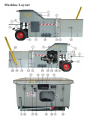
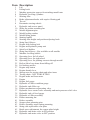
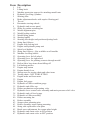
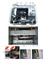
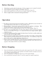
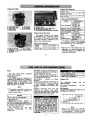
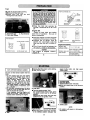
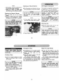
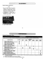
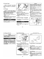
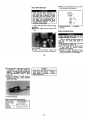
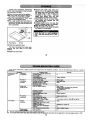
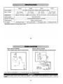
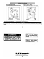
The
Pro Kerb
CKC Civil Construction
Equipment Pty Ltd
For Sales, Service, Spare Parts or further information please use the details below.
Phone / Fax - 07 3881 2862
Mob - Mike - 0427 006 765
- Tim - 0419 737 041
Email - [email protected]
Web - www.ckcequipment.com.au
Postal Address - PO Box 41
Strathpine
QLD 4500
Australia
International callers please use country code 61 and remove the 0 from the front of all numbers
Contents
Machine Layout
Page 4-7
Machine Layout Table
Page 5-6
Before Starting
Page 8
Operation
Page 8
Before Stopping
Page 8
Mould Changes
Page 9
Specification
Page 9
Servicing and Maintenance
Page 10
Troubleshooting
Page 11
Engine Owner’s Manual
Page 12-23
Machine Layout
Item Description
1
2
3
4
5
6
7
8
9
10
11
12
13
14
15
16
17
18
19
20
21
22
23
24
25
26
27
28
29
30
31
32
33
34
35
36
37
38
39
40
41
42
43
44
45
46
47
Lid
Lifting hook
Machine protection spacers for attaching mould onto
Hydraulic levelling cylinders
Steering tiller
Brake adjustment knobs with captive floating pad
Tie rod
Pneumatic steering wheels
Hydraulic tank access panel
Slides for pusher mounting bar
Mould alignment pins
Mould locking catches
Mould lifting points
Starting handle
Steering tiller height and position adjusting knob
String line follower
Engine slide locking bolt
Engine and hydraulic pump unit
Spirit level holders
String line follower - Not available on all moulds
Machine levelling bubble
Operating lever for left wheel
Operating lever for right wheel
Operating lever for pushing concrete through mould
Rail on lid to keep items from falling off
Lid locking catches
Engine stop button
Engine throttle lever
Storage area for towing chain and other items
Towing chain - NOT FOR LIFTING
Engine tacho and hour meter
Engine
Engine fuel gauge
Hydraulic oil filter condition gauge
Hydraulic tank filler cap
Pusher mechanism reciprocating valve
Hydraulic lever control valve assembly and main pressure relief valve
Hydraulic tank oil level gauge
Hydraulic oil filter assembly
Pusher mounting bar
Kicker assembly
Scraper plate mounting pins
Kicker assembly return spring mounting
String side replaceable wear plate
Bottle screw adjustment for scraper plate height
Hydraulic tank main valve in ON position
Hydraulic tank main valve in OFF position
Before Starting
1.
2.
3.
4.
5.
Check there is petrol and oil in the motor - Refer to engine owner’s manual for details.
Check hydraulic oil level using the tank gauge. (Item 38)
Ensure that the hydraulic oil tank valve is in the on position. (Item 46)
Ensure all operating levers are level prior to starting. (Items 22, 23 and 24)
Refer to engine owner’s manual for starting instructions.
Operation
1. The right lever (Item 24) will cause the machine to operate. When all levers are level the oil
goes straight back to tank and not over any pressure circuit.
2. Adjusting height. Experienced operators do this while the machine is stationary. This
needs a little practice to get in time with the reciprocating valve.
3. Lateral level. Level the mould and then zero the level on the machine. (Item 21)
4. Since there is no centrifugal clutch you can run the engine at what ever speed you require
but try to avoid about 2250 rpm. It is around here that most single cylinder engines
vibrate the worst.
5. If you have compaction problems apply the brakes (Item 6) but this is usually needed only
down hill and with the bigger moulds.
6. Adjust the string line pointer (Items 16 and 20) to suit what you are doing. If deeper kerbs
than normal are specified add skids below the mould. Note – the mould has a slope built
into it so the unit as a whole should run relatively level.
7. There is a captive towing chain (Item 30) located in the towing chain storage area (Item 29)
which can be used for towing the machine past gullies and other areas where kerb is not
required. This chain is NOT to be used for lifting!
Before Stopping
1.
2.
3.
Ensure the hydraulic ram attached to the pusher plate mount (Item 40) is fully retracted.
This will prevent any damage to the hydraulic ram shaft should the machine be lowered
onto anything while being moved.
Ensure the hydraulic levelling rams (Item 4) are at the required height.
Press and hold the Stop button (Item 27) until the engine has stopped completely.
Mould Changes
Slot pusher plate into pusher plate mounting bar. (Item 40)
Slide scraper plate onto scraper plate mounting pins. (Item 42)
Adjust the height of the scraper plate using the scraper plate adjustment bottle screw (Item
45) so that the scraper plate is just above the pusher plate. The piece of wire is to prevent
the bottle screw from self adjusting due to vibration.
Slide mould into position using the mould alignment pins (Item 11)
Once correctly located against the machine protection spacers (Item 3) flick the locking
catches (Item 12) into the vertical position.
Reverse the above procedure to remove the current mould.
The above procedure does take a little practice to get right but with the help of a regular
hammer and pry bar the entire mould change procedure can be completed by two people in
under 2 minutes without the need for any spanners.
The machine protection spacers (Item 3) should never need to be removed from the
machine.
Specifications
Item
Description
Width
820mm
Height
960mm
Length
Machine - 1600mm
Weight
Machine - 310Kg
Engine
13hp 4 stroke
Pump
Salami
Mould - 875mm
Mould - 150Kg
Levelling Ram
Nordon Industrial Grade with 14" stroke
Pusher Ram
Nordon Excavator Grade with 8" stroke
Min kerb radius
Max kerb size
1000mm
700mm wide
Overall with mould - 2475mm
Servicing and Maintenance
Engine maintenance is as per owner’s manual. Please consult this documentation for further
information. To perform maintenance on the engine undo the engine slide locking bolt (Item
17) and slide the engine out.
When Item
Daily
Daily
Daily
Check
Item 4 Check for any seepage which could indicate a oil leak.
Item 8 Ensure correct pressure and tyre condition.
Item 10 Ensure no blockages or debris in slide mount and that the ram mount
(Item 40) is not making metal to metal contact with the machine frame.
As the metal channel will wear out prior to the urethane block it has
been designed to that the metal channel can be inverted and reused prior
to complete replacement of channel.
Weekly Item 14 Check pull start cable to ensure good condition.
Weekly Item 28 Ensure free movement of throttle level. Should this become stiff drop
some standard light oil down the cable located behind the lever.
Weekly Item 34 Check this gauge to determine when hydraulic oil filter needs to be
replaced. This needs to be done with the engine running at medium
revs.
Weekly Item 44 Ensure that wear plate has not worn through to the machine body.
Various Item 18 Perform checks as specified in the engine owner’s manual. Hydraulic
pump unit does not need servicing.
Various Item 32 Perform checks as specified in the engine owner’s manual. Hydraulic
pump unit does not need servicing.
Troubleshooting
If the hydraulics ever jam up there is a little stimulator on the reciprocating valve (Item 36).
Push it one way or the other and the valve will resume. The stimulator is located in the front
and rear face of the valve in the centre of the large bolt head.
The pressure settings for the reciprocating valve (Item 36) are facing inwards and need a
10mm spanner and an allen key to adjust. They determine the pressure at which the cylinder
changes direction. If for some reason it changes too soon the pressure needs increasing by
screwing the adjusting screw in. Give it only sufficient pressure to do its work. The main
pressure setting is on the valve block (Item 37) and is set at 1000psi. The reciprocating
pressures are approximately 400 and 500 psi but it is very hard to judge this with an analogue gauge. Generally if you have trouble it is something in the works such as a solid piece
of dried concrete or something else. Before making any of the above mentioned adjustments
please call us for the latest advice.
The point for testing pressures is located on the lower string side of the machine on the main
valve block (Item 37). The system relief valve is located on the string side of the machine
on top of the main valve block (Item 37).
On a new machine the slides (Item 10) may bind. To resolve this just spray some water in
them. Once the machine has done some hours work this will no longer happen.
Engine Owners Manual