1
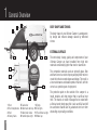
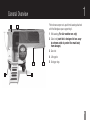
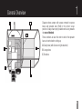
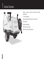
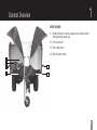
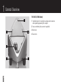
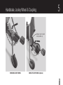
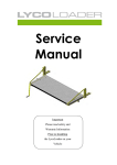
OWNERS MANUAL
XTRK & XPLOR MODELS
Forward
Welcome out our growing family of owners. This camper
has been delivered to you with confidence. Your camper
has been built with pride and strict quality control.
This manual has been prepared to help you understand
the operation and maintenance of your camper; it explains
the features of your new camper trailer from Ultimate
Campers.  Please read this manual thoroughly and follow
the instructions carefully so that your camper will provide
many years of trouble-free adventures.
A separate warranty information sheet explains details
about the warranties covering your camper.
When it comes to servicing your camper, remember that
your Ultimate dealer/service agent knows your camper
best and is dedicated to your complete satisfaction.  When
you require any service or have any questions, we will be
glad to provide you with quality maintenance, advice and
any assistance you may require.
All information and specifications in this manual
are current at time of printing, however, because
of Ultimate Off-Road Camper’s policy of continual
product improvement; we reserve the right to make
changes at any time without notice.
This manual applies to all models and explains all
equipment, including options; therefore you may find
explanations for equipment not installed on your camper.
NOTE: Because each camper can have different
equipment in terms of appliances such as fridges,
stoves, hot water systems, stereo units etc ... please
refer to the individual appliance manuals for the
appliance relevant to your camper.
Contents
Section 1
General OverView1-9
Section 6
CAMPER SET-UP
Section 2
10
SIDE LOCKERS - GAS SYSTEM
• Cook Tops (Refer to individual appliance manual)
• Hot water System (Refer to individual appliance manual)
Section 7
BASIC CANVAS
(Extra info refer to individual instructions)
Section 3
SIDE LOCKERS - ELECTRICAL
• Fridge (Refer to the individual appliance manuals)
• Stereo/Radios/CD Players (Refer to the individual
appliance manuals)
SIDE LOCKERS - TOILET
17-20
21-24
Section 8
PACKING UP
25-26
Section 9
CLEANING & MAINTENANCE
27-31
11
12
Section 4
ELECTRICAL SYSTEMS
13-14
Section 5
HANDBRAKE, JOCKEY WHEEL & COUPLING
15-16
Section 10
SPECIFICATIONS 32
1 General Overview
2
3
BODY SHAPE AND TOWING
1
The body shape of your Ultimate Camper is aerodynamic
by design and reduces damage caused by deflected
stones.
EXTERNAL SURFACE
4
6
5
7
2
11
8
10
9
12
1
2
3
4
1
Boot
Roof clampdowns
Roof
Safety chains
5
6
7
8
9 Steps
Gas locker
Water tank drain tap 10 Tail lights
Water/toilet locker 11 Flood/Reverse light
Number plate light 12 Water cap
The entire body, lounge, galley and components of your
Ultimate Camper are hand moulded from high tech
materials considerably lighter than steel or aluminium.
The composite materials used are primarily glass fibre
and foam cores in a matrix of epoxy and polyester resins to
create the intricate curved shapes and design. The result is
a low maintenance and durable product that will, with the
correct use, provide years of enjoyment.
The protective paint on the outside of the camper is a
tough, durable, anti chip product that is sacrificial over
time. The chassis is made of Duragal that is coated with
a flexicoat under body spray this is also sacrificial and will
be sand/stone blasted back to galvanised steel over time
depending on prevailing conditions.
1
General Overview
1
Photo shows camper set-up with mini awning attached
with the fibreglass spars supporting it.
2
1 Mini awning (For fair weather use only)
2 Safari roof (note this is designed to tear away in extreme winds to protect the main body from damage).
3 Gas strut
4 Lifting pole
3
5
4
5 Outrigger legs
5
2
1 General Overview
UNDER REAR VIEW
1 Recovery points
2 Watertank drain tap
3Spring
4 Shock absorber
5 Jacking point (changing tyres) under swingarm shock-
mount
6 Outrigger leg (in down position)
7 Outrigger leg (in up position)
8 Locating/adjusting pin
4
2
5
3
1
3
7
6
8
1
General Overview
1
Diagram shows camper with canvas removed to expose
bows and spreader bars (1-4) in the correct set-up
position. Always have spring loaded ends facing towards
the rear of the bed.
3
B
These numbers are also the order in which the spreader
bars are inserted when setting up.
C
A
A Galley bow (with fluorescent light attached)
B Lounge bow
C Bed bow
2
4
4
1 General Overview
1
5
6
Ensure no canvas is outside of main body seal when
folding down.
3 4
2
1 Side clampdowns
2 Rear clampdown (right hand side of rear door)
3 Lifting pole
4 Number plate light
5 External 12 volt socket
6 Reverse and flood light optional
5
5
1
General Overview
BOOT (XPLOR)
1 Handles/Steps for moving camper and to stand on when setting/packing camper up
2 Jerry can holder
3 Boot clamp down
4 Optional water heater
2
4
3
3
1
1
6
1 General Overview
THE BOOT (XPLOR) continued
On the back wall of the front boot is a service panel. This
is held in place with self-tapping screws. This panel
provides access to the rear of the fridge for cleaning and
maintenance.
7
1
General Overview
THE BOOT (XPLOR boot continued)
1 Fridge Service panel
2 Jerry can holder (Jerry cans not supplied as standard)
3 Gas strut for Gull wing
4 Pole racks for storing main awning poles etc
5 Hot water system (optional)
1
3
5
2
4
8
1 General Overview
THE BOOT (XTRK Model)
3
1 Handles/steps for moving the camper and to stand on when packing unpacking the camper
2 Jerry can holder (jerry cans not supplied)
4
4
3 Boot lock
4 Gas struts
2
1
9
1
2
Side Lockers - Gas System
FORWARD PASSENGER SIDE GAS STORAGE
LOCKER (XPLOR)
Gas bottles are stored in the front left locker. Standard
equipment is a 3.8Kg bottle. The locker compartment is
vented in the front left hand corner.
CAUTION:
ENSURE VENT IS NOT INADVERTANTLY BLOCKED
CAUTION:
PLEASE READ AND FOLLOW THE INSTRUCTIONS ON THE
CONSUMER PLATE LOCATED IN YOUR CAMPER AND
ALWAYS ENSURE THAT THE GAS BOTTLES ARE SECURE
•
To turn gas on, turn tap on bottle anti-clockwise.
‘Above the regulator there is one valve cock for the
stove. If the Hot Water Service is installed a second
valve is fitted.
•
To switch valve cocks OFF, tap should be in the vertical
position (ON is horizontal).
•
When travelling switch ALL GAS OFF at the bottle,
valve cocks and fridge and turn fridge to 12 volt. An
extra 3.8Kg bottle can be installed for back-up or gas
BBQ.
10
3 Side Lockers - Electrical
ELECTRICAL LOCKER
The forward driver’s side locker is the electrical locker
and contains the major electrical components/controls.
A battery is mounted in the Electrical locker.  This
charges via the vehicle whilst driving. When using the
on board battery charger and you are staying at a powered
site, connect both the fridge and charger together using a
power board.  Plug power board into the power.
The isolation switch TURNS clockwise - turning ON the
12 volt power to the camper.  Turned anti - clockwise
disables power.
4
1
1 Battery
2 Charger
3 Isolation switch
4 Fuse
5 Fridge Lead
11
3
2
5
The rear drivers side locker is a spare storage locker.  It
can be used to carry the wine cellar. (Optional)
NOTE: Image shown is of the XTRK electrical locker.
Other models may have dual battery set-up.
3
Side Lockers - Toilet
REAR PASSENGER SIDE LOCKER
The rear passenger side locker is the toilet compartment
or if a toilet is not fitted is a spare storage locker it has
both internal and external access (XPLOR models only), it
is optional in XTRKs. It may also contain the shower head
and tap if an XPLOR or optioned.
Do not put excessive weight on the doors Maximum weight limit on the doors is 8Kg.
There is a plastic clip fitted to the body end of the wire
stay, this is designed to give way under load so that no
damage is done to the camper body or the doors.
12
4 Electrical Systems
Electrical switches (on left when entering the camper)
control the following:
• Rear floodlight (if installed)
• Water pump
• Galley light
• Exterior 12 volt outlet
The three outlets above the fridge (right hand side of the fridge if an XTRK) are permanently live (after switching on the isolation switch).
There are also 2 12 volt outlets located beside the outside
gas strut and on the rear passenger corner.
NOTE: Water level indicator is operated by pressing
the water button.
13
Electrical Systems (XPLOR & XTRK Models)
4
ELECTRICAL
Ultimate Campers use a 7-pin Anderson plug.
The Andersons plug is heavy duty and is used for:
•
charging battery
•
earth return
NOTE: The rubber loop on the trailer leads of all
models loops over the T Handle of the Treg Coupling
whe hitched and holds the leads in place.
14
5 Handbrake, Jockey Wheel & Coupling
All models come with a choice of either swing up or removable jockey wheels.
1 2
q
3
3
q
5
6
Electrical plug and chains not shown for clarity
4
Removable JockEy Wheel
15
SWING UP JOCKEY WHEEL (Optional)
1 Treg coupling 3 Jockey wheel
2 Grease nipple 4 Handbrake (shown off position)
5 Handbrake cable
6 Draw bar
5
Handbrake, Jockey Wheel & Coupling
Release lever to swivel
Jockey wheel up
Removable jockey wheel
Swing up jockey wheel (Optional)
16
6 Camper Set-up
Picking a Spot
Remember when picking a camping spot that normal
safety considerations must be taken into account.
1 Flat and reasonably level land
2 Not likely to be flooded whilst you’re camping there
3 Firm ground (not prone to give way and slip)
4 No overhanging trees (risk of damage by falling branches)
5 Space for lid to open
17
6
Camper Set-up
LEVELLING PROCEDURE
The more level the ground is, the less time/effort is
required for levelling.  By following six simple steps the
levelling procedure should be quick and easy.
1 Install/swing down jockey wheel.
2 Engage handbrake and chock wheels.
3 Wind jockey wheel down and Unhitch from vehicle. (camper should be nose down)
Camper weight should be distributed between the wheels
and three outriggers.
CAUTION
• Lifting tyres off the ground should be avoided.
•When using the jockey wheel, lift the rear stairs up or damage may occur.
4 Assess left/right level and install down side rear Out- rigger. (Use the supplied ply pads if ground is soft)
5 Wind jockey wheel until driver’s side front is slightly higher and the camper is level front to back. Install other outriggers.
6 Install front outrigger and wind down jockey wheel until some weight is on the front outrigger.
18
6 Camper Set-up
OPENING CAMPER
1 Unclip and lower steps.
2 Unlock and open back door.
3 Undo rear, rear-side, front-side lid clampdowns.
4 Standing on the bumper push lid up to vertical position.
1
2
5 Holding onto centre canvas bow (through the canvas), guide lid to horizontal position.
6 Or if preferred from the ground using the lifting pole rest
pole in cup of hand on thigh and walk forward to push lid
up and over.
19
3
4
5
6
6
Camper Set-up
OPENING CAMPER (Continued)
7-7a Lift gallery bow, step inside and using the c clip click
the first spreader bar on the far side and then clip the
second spreader bar into position.
7
7a
8 Release velcro tab and push up the bed bow with the
two long spreader bars, then slide the spreaders into
position.
9 Place three mattresses from the lounge to the bed.
10 Install pedestal and table offset facing towards the
lounge if required.
8
11 Secure canvas storm flap to body.
9
10
(For detailed instructions on fridge operations please
refer to manufacturers manual provided).
11
20
7 Basic Canvas
SAFARI ROOF/ MINI AWNING
WARNING:  In extreme wind conditions the leading
edge of the safari roof must be pulled down to
reduce the risk of it being blown off.
MINI AWNING
1 Zip mini awning onto rear of the main roof.
2 The long spar is passed through the outer edge of the awning.
3 The 2 smaller spars Velcro to the outside of the larger spar.
4 Pass through the two bottom saddle brackets on either side of the camper.
NOTE: Store spars behind lounge cushions when not
in use.
21
7
Basic Canvas
INSTALLING THE MAIN AWNING
1 Standing on the rear bumper step, start the zipper off
on the passenger side of the main body and pull zip as
far as possible.
2 Step back onto ground and use lanyard to complete the
rest of the zip.
3 Cover the zip with the storm flap using “stay puts”.
4 Secure both ends using the Velcro and eyelets located
at each end of the awning.
5 Starting at the corners install the 6 adjustable poles
under the awning to hold it up.
6 Use the ropes to hold the awning in place and peg into
ground.
22
7 Basic Canvas
INSTALLING THE SUNROOM
1 Position panel 1 near the back door, and Velcro
across the top of the panel and press stud down the
side of the camper
2 Continue with panels 2,3,4 around to the other side
of the awning.
3 Press stud the under bumper skirt along the back
chassis rail.
4 Fit the under bed panel with the Velcro along the
main canvas body and press stud don the side
of the camper and zip down the canvas side to
enclose.
NOTE: For detailed instructions please refer
to installation guides supplied with individual
canvas components.
23
7
Basic Canvas
Front of camper
Lid/bed
Camper above shown fully set up with Sunroom and Spare
Room.
NOTE:  Level ground is required for a quality fit of
Sunroom and Spare Room.
Sketch showing canvas panel positions
Under bumper skirt
4
Poles
3
1
1-4  Awning/sunroom combo panels
2A
Awning/annex
2B
24
8 Packing Up
1 Ensure all loose items inside the camper are stored in
the appropriate place.
lid seals. Make sure there is no canvas caught between
the lid and the body.
2 Ensure fridge door has click locked.
3 Ensure all locks are in closed position on all drawers
and doors.
4 Turn OFF all electrical switches on switch panel.
5 Turn all gas OFF.
6 Turn 12 volt electrical isolation switch OFF.
7 Unclip the canvas storm flap.
8 Remove and pack bedding on to the lounge with
spread-er bars and table packed between mattresses.
(See page 26 for sketch on where things go)
9 Using the lifting pole on the rear edge of the lid out
standing on top of steps and pulling the centre bow
over lift the lid up through the vertical and begin to
close the lid.  If lifting the lid by yourself ensure the
lifting pole has been released so you can use it as a
stop if required once the lid is in the horizontal position
walk around and tuck any protruding canvas behind the
25
BEFORE LEAVING WALK AROUND AND CHECK ALL
LOCKS, HITCHING, STAIRS AND STABILIZER LEGS ARE
IN TRAVELLING POSITION.
8
Packing Up (diagram) - during your trip
Side wall of camper
Lounge back cushion
Spreader bars
Mattress 3
Mattress 2
Mattress 1
Lounge cushion
Storage bin under Lounge
Wheel Arch
Lounge and cushion laid
down on lounge cushion
Table upside down
Table leg
Mini spars tucked
Behind main lounge
VIEW SHOWING WHERE TO PACK THINGS WHEN FOLDING UP
IMPORTANT: whilst travelling follow the checklist
below at regular stops.
1 When you exit your towing vehicle visually check that
the camper is sitting square and level, as an indication
of the tyre pressure.
2 Walking towards the camper, check the safety chain
and electrical plug, both visually/physically, to ensure
that they are fitted correctly.
3 Check the treg pin and retaining pin are fitted correctly.
4 Visually check locker doors are closed correctly and
preferably locked.
5 Check roof clampdowns are secure in the down position.
6 Check steps are secure in the up position.
7 Regularly check tyre pressure, wheel nuts, and bearings for heat and movement as the presence of heat or
wheel play may indicate loose wheel nuts or potential
bearing failure.
26
9 Cleaning & Maintenance
HANDBRAKE MAINTENANCE
JOCKEY WHEEL
1 Pull handle up to engage hand break. (Always engage handbrake when your camper is unhitched from the vehicle however do not rely solely on handbrake).
The jockey wheel mounts on the right hand side of the
drawbar.  If fitted the removable jockey wheel is stored in
the boot when not in use.
2 Chock the wheels.
Shock Bush Replacement Part Number:  Comes as a
kit which includes four bushes. (Made by Mackay Silent
Ruba).
3 Unhitch camper.
4 To release handbrake to move or tow camper push button at the end handle to disengage brakes.
5 Keep all movable parts clean and free of contamination.
6 Keep all movable parts greased with a good quality grease.
Handbrake cable
The handbrake cable is adjustable half way down where it
divides and branches off to each wheel: To adjust 1 Loosen lock nut.
2 Turn curled knob to take the slack out of the cable.  Ensure the brakes are not dragging.
3 Tighten lock nuts.
27
Kit No: A1178 shock absorber bush Holden 1971 - ON.
WARNING: Always check wheel nut tension before, during and after towing the camper. This is
especially important if you have changed a wheel,
had work done on the brakes or wheel bearings.
BEARINGS
It is important that you service and maintain
your wheel bearings regularly particularly after
extensive off road use and water crossings.
NOTE: For bearing maintenance and further information please refer to the manufacturer’s instructions.
9
Cleaning & Maintenance
q
BRAKE MAINTENANCE
Backing plate
Adjusting tool
LESS
With the camper hitched to the vehicle for safety, chock
opposite side wheel - handbrake in the off position.
Jack the wheel to be adjusted just off the ground.
Remove oval shaped rubber plug from inside of drum
backing plate, use a flat blade screwdriver to turn the
star wheel until the brake drag makes it difficult to
turn the wheel.
Star wheel
The star wheel can then be turned in the opposite
direction 3/4 to 1 revolution to allow the wheel to turn
freely when spun.
Repeat procedure on other wheel.
MORE
q
28
9 Cleaning & Maintenance
CHASSIS LUBRICATION
1 Please change this to ‘On the front of the swing arms
(2 per swing arm). Undo these bolts.
2 Using a good quality grease (Castrol APXT or similar), apply until grease is pushed from both sides of
the bush.
Note: This grease is not intended to lubricate the
bush but rather to exclude dirt and water from the
bush.
3 Grease the treg coupling using the same grade grease.
29
9
Cleaning & Maintenance
CANVAS CARE INSTRUCTIONS
•
New canvas should be thoroughly wet before use and
allowed to dry.  Repeat 2 to 3 times to ensure sealing up
of the seams.
•
Clean only with cold water and a brush - do not use
soap or detergent.
•
Ensure canvas is stored completely dry prior to storage.
•
Do not store directly on concrete floors.
•
Do not expose to petrol, oil or solvents.
•
Restore well worn products with Reproof.
•
Be sure organic and vegetable matter (grass, dirt etc)
and bird droppings particularly are not left in contact
with the canvas for any prolonged period.
•
If signs of mildew ever appear, brush off before it becomes attached.
•
Note: If mildew persists it can be treated withdiluted
bleach (Lemon White King) 1 part bleach, 5 parts
water. Once dry allow approximately a further 12
hours then thoroughly hose off and again allow to
dry before applying Wax Converters Reproof  water
proofer and mildew inhibitor.
30
9 Cleaning & Maintenance
CLEANING YOUR CAMPER
Because your ultimate is built using the same
materials as that in boat hulls the body has a life
that can be measured in decades however to keep
your camper looking new it is recommended that you
clean it regularly by following the instructions below.
31
•
Use car wash in a hand held spray bottle and a soft
bristled brush to clean the outside of the camper.
•
Wet camper down and spray on the wash, brush and
scrub, then hose off.
•
Use on all external surfaces of the camper and trailer
when folded down.
•
To polish camper, Ultimate provide a fibre glass restorer
and wax which is very easy to use.
•
Follow the directions on the bottle - it can be used on
any of the gloss surfaces inside and out.
If doing any beach work, wash the camper and chassis
down with soapy water and then rinse with lots of fresh
water.
10
Specifications
General
Fuses
Overall length
4250 mm
Overall width
2000 mm
Overall height
1800 mm
Dry weight
Wheel track
XPLOR 850 kg (XTRK 750kg)
1600 mm or to suit vehicle
Ground clearance
570 mm
One (1) 3.8Kg Gas Bottle
Manchester
Water Tank capacity
Fuses are found behind the facia of the switch panel
above the top left hand drawer.
110 litres
32
PHONE 02 4474 4410
•
EMAIL [email protected]
•
WEB www.ultimatecampers.com.au