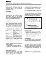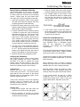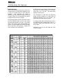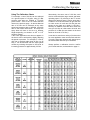
1
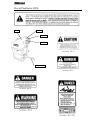
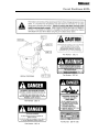
Operators Manual
MANLINK-4 REV A 16/09/04
400L / 600L Pasturepak
Linkage Sprayer
SILVAN AUSTRALIA PTY. LTD.
ABN 48 099 851 144
VICTORIA (HEAD OFFICE)
QUEENSLAND
89 Lewis Rd, Wantirna South 3152
44 Lysaght St.
WESTERN AUSTRALIA
Hanwell Way
Telephone: (03) 9887 2788
Acacia Ridge 4110
Bassendean 6054
Facsimile: (03) 9887 1035
Telephone: (07) 3345 9500
Telephone: (08) 9279 0800
Spare Parts Facsimile: (03) 9887 1637
Facsimile: (07) 3345 9511
Facsimile: (08) 9279 0810
www.silvanagcess.com
Introduction
Silvan is an Australian owned company specialising in supply of crop protection equipment to primary
producers. A leader in the design of agricultural sprayers, the company was established in 1962 and has
grown to become the largest manufacturer and supplier of crop protection equipment in Australia.
Our operations are fully accredited to the international quality standard ISO 9001 and we are extremely
proud of our reputation for quality products backed by quality service. Your investment in a Silvan sprayer
is an investment in quality.
This manual covers the 400L and 600L Pasturepak units, which have been designed and manufactured
to provide a high standard of performance and safety and incorporate many innovative features. To
ensure continued efficient performance and safe operation of your sprayer, you need to read this manual
thoroughly and fully familiarise yourself with all aspects of the sprayers operation, maintenance and
safety procedures.
Now that you are a proud Silvan owner, all our services and dealer support are available to you should
you need them. We assure you of our best attention at all times.
No liability can be accepted for any inaccuracies or omissions in this publication, although due care has been taken
to make it as complete and accurate as possible.
The information, illustrations and technical data were considered to be correct at the time of preparation.
In accordance with our policy of continuous development, Silvan Australia Pty. Ltd. reserves the right to make
changes at any time without notice.
Contents
Warranty
About your warranty.
New Product Warranty Policy.
2
3
Safety Information
4
Specifications
7
Operation
Attaching the tractor to the PTO drive
Starting the Sprayer
3 outlet control, Fresh Water Tank and Toolbox
Spray Booms
Spray Guns, Hose Reels and Foam Marker
8
8
9
9
10
General Spraying Information
When to spray, field patterns, droplet size.
Nozzle height, application rate, ground speed
11
11
Calibrating the Sprayer
Testing, varifying calibration, nozzle maintenance
Nozzle selection
12
13
Lubrication and Maintenance
15
About Your Warranty
Silvan Australia Pty. Ltd. welcomes any
warranty repair and apologises to you for
any inconvenience caused. See the next
page for the statement of your legal
warranty coverage. The following
information will assist your understanding of
warranty procedures.
Any authorised Silvan dealer service outlet
can perform warranty repairs for you,
however, we recommend that such repairs
be carried out by the Dealer from whom you
bought the machine.
Most warranty repairs are handled routinely,
but sometimes requests cannot be accepted
under warranty. Normal wear and tear is not
covered by warranty nor does warranty
apply if a product failure can be attributed to
abuse or neglect.
Whilst Silvan will abide by its warranty policy
under all genuine circumstances, we must
emphasise that such can only apply when
our equipment has been used in
applications for which it was designed and
manufactured and that a reasonable degree
of care and common sense has been
exercised by the operator.
Warranty Repair Site.
The warranty provides for repairs to be
carried out at the servicing dealers normal
place of business. An owner may elect to
have repairs carried out at his own
residence but, whilst Silvan will accept the
actual repair cost of the failed component(s),
the travelling costs will not be covered under
warranty.
Items Not Covered By Warranty.
The warranty does not allow for the cost of
the following items: These are the
responsibility of the owner.
1. Labour to travel to and from a brokendown machine or for any distance
charges.
2. Labour premiums that might apply for
any repairs that are made outside the
dealers normal business hours.
3. Transportation costs of the machine to
and from the service outlet.
4. Freight costs to get parts to and from
the service outlet.
5. Telephone and fax calls made by the
owner in connection with the warranty
repair.
New Product Warranty
WARRANTY POLICY
Silvan Australia Pty. Ltd. warrants to its authorised dealer, who in turn warrants to
the original purchaser (owner) of each new Silvan product, that it will repair or
replace, without charge for labor or parts, any defective or malfunctioning parts in
accordance with the warranty limitations and adjustments schedule below.
PRIVATE DOMESTIC - 12 MONTHS
PRIVATE and COMMERCIAL AGRICULTURE - 12 MONTHS
AGRICULTURAL CONTRACTORS – 6 MONTHS
GOVERNMENT and MUNICIPAL DEPARTMENTS DEPTS- 6 MONTHS
ALL NON-AGRICULTURAL APPLICATIONS - 3 MONTHS
HIRE COMPANIES – 3 MONTHS
The warranty period will begin on the date the product is delivered to the first retail
purchaser.
THIS WARRANTY COVERS:
·
·
·
·
· Only conditions resulting from defects in workmanship or material under normal
use and service.
THIS WARRANTY DOES NOT COVER:
Conditions resulting from misuse, negligence, alteration, accidental damage or
failure to perform normal maintenance services;
Any product which has been repaired by other than authorised Silvan Australia Pty.
Ltd. service outlet so as , in any way in the sole and absolute judgement of Silvan
Australia Pty. Ltd. to affect adversely its performance and reliability;
The replacement of wear and tear items such as diaphragms, V-Belts and ground
engaging components;
Loss of time, inconvenience, loss of use of the product or other consequential
damages.
The repair of defective products qualifying under this warranty will be performed
by an authorised Silvan Australia Pty. Ltd. Service outlet within a reasonable time
following the delivery of the product, at the cost of the owner, to the service
outlet’s place of business. The product will be repaired or replaced, using new
parts sold by Silvan Australia Pty. Ltd.
The owner is responsible for the performance of regular maintenance services as
specified in the Owners/Operator’s Manual applicable to the product.
· THIS WARRANTY IS THE ONLY WARRANTY APPLICABLE TO
SILVAN AUSTRALIA PTY. LTD. NEW PRODUCTS AND, TO THE
MAXIMUM EXTENT PERMITTED BY LAW, IS EXPRESSLY IN LIEU
OF ANY OTHER WARRANTIES EXPRESSED OR IMPLIED,
INCLUDING ANY IMPLIED WARRANTY OF MERCHANT ABILITY
OR FITNESS FOR A PARTICULAR PURPOSE.
· SILVAN AUSTRALIA PTY. LTD. DOES NOT AUTHORISE ANY
PERSON TO CREATE FOR IT ANY OTHER OBLIGATION OR
LIABILITY IN CONNECTION WITH THESE PRODUCTS.
· SUBJECT ONLY TO LEGISLATIVE OBLIGATIONS TO THE
CONTRARY, SILVAN AUSTRALIA PTY. LTD. SHALL NOT BE
LIABLE FPR INCIDENTAL OR CONSEQUETIALDAMAGES
RESULTING FROM A PRODUCT PERFORMING IN BREACH OF
THIS WRITTEN WARRANTY
Safety Information.
Before operating the sprayer read the following safety instructions.
Failure to comply with these warnings may result in serious injury or death.
·
·
This
sprayer
is
designed
and
manufactured solely for the purpose of
applying agricultural chemicals to crops.
Under no circumstances should it be
used for any other purpose.
·
Before using the sprayer carefully read
and ensure you understand the contents
of this manual and any other manual
supplied with the sprayer.
·
Before operating the sprayer, read all
the safety warnings, which are carried
on various parts of the machine. Refer
to the next page for a location diagram
and the wording of these warnings.
·
Never allow an inadequately trained
person to attach or operate the sprayer.
·
Do not operate the sprayer whilst
wearing loose clothing, unrestrained
long hair, jewelry or anything which
could become entangled in rotating
components or limit your vision.
·
Wear ear protection when operating the
sprayer on a tractor which is not fitted
with a sound proofed cabin.
·
Ensure the linkage capacity of the
tractor is suitable for the loaded mass of
the sprayer. Refer to the tractor
operator’s manual for safe working
loads and relevant tractor safety
instructions.
·
Exercise extreme care when operating
in hilly or uneven terrain to ensure
proper stability. Refer also to the tractor
manufacturer’s operating and safety
instructions.
·
Do not operate the sprayer at speeds
greater than 540 PTO rpm
·
Do not operate the sprayer without all of
the tractor and sprayer safety shields in
place. Carefully check that PTO and
driveline shields are correctly installed.
·
Stop the tractor PTO, apply the parking
brake and switch off the tractor engine
before approaching the sprayer and
performing any work on it.
·
Disconnect the PTO shaft at the tractor
and ensure the sprayer is properly
supported before performing any
maintenance work.
·
Before use of any chemicals refer to
the chemical manufacturer’s label and
safety instructions for safe handling
procedures and correct method of use.
Always use the recommended personal
protective clothing and equipment.
·
Always wear gloves when removing and
cleaning filters
·
Dispose of empty chemical containers in
accordance
with
the
instructions
supplied by the chemical manufacturer
·
Ensure that all operators and associated
personnel are familiar with the legal
regulations and codes of practice that
apply to the safe use and storage of
spray chemicals.
·
Ensure chemicals are kept away from
fresh water tank. Never drink water from
fresh water tank.
Decal Positions 400L
DEC 48
DEC 12
DEC 10
DEC 13
399 14 1000
Decal Positions 600L
Specifications
This sprayer is designed and manufactured
solely for the purpose of applying agricultural
chemicals to crops. Under no circumstances
should it be used for any other purpose.
Spray Booms (Optional)
Field
Galvanized steel truss
6 or 8m
Three section horizontal fold
Tank
Low-line designed tank constructed from
Polytuff impact resistant polyethylene.
Capacity 400 / 600 litres with calibrated
external sightline.
255mm diameter screw down lid with basket
strainer.
15 litre fresh water tank with on/off tap.
4 litre toolbox with easy access Polyethylene
lid.
Continuous by-pass agitation to bottom of tank.
Fieldmaster
Galvanized steel truss with nozzle protection
10 or 12 m
Three section horizontal fold.
Double fold outer arms
Suspension and height control
Pumps
Positive displacement oil-backed diaphragm
pump of varying size depending on sprayer
specification. Output at 540 PTO rpm and
maximum operating pressure as shown below.
Pump No.
BP 60/20
BP 125/20
Output
l/min
58
121
Max. Pressure
Bar
psi
20
290
20
290
Vine Boom
8 or 12 Jet
Olive Boom
7 Jet
Adjustable telescopic arms
Adjustable brass nozzles
Adjustable sliding arm
Adjustable brass nozzles.
Sprayguns (Optional)
Topline
On/Off Trigger
Maximum pressure 5000Kpa
Longranger
Two Handed Grip
Maximum pressure 5000Kpa
Airvac
Venturi Shrouded nozzle
atomizer.
Maximum pressure 5000Kpa
Drive
540 rpm PTO shaft with safety shields.
Controls
Screw type pressure regulator.
Glycerine filled pressure gauge.
3 boom outlets.
Dimensions and Weights
Length L, Width W, Height H, all in (mm).
Mass kg with tank empty. To calculate gross
Mass add 1kg/litre capacity (eg 400L = 400kg)
Filtration
Three stage with removable elements on all
units or four stage if fitted with optional boom
section filters.
Standard mesh shown. Alternatives available.
Sprayer(w/out boom)
1)Tank lid strainer
2)Suction line filter (blue).
3)Boom nozzle strainers
18 mesh.
50 mesh
50 mesh.
Frame and Hitch
Heavy duty galvanized steel construction.
Reversible Category 1 & 2 linkage pins.
Hose Reel + Spraygun
Rear mounted Hose Reel with 20M of 12mm
I.D pressure hose and Silvan Triam 44 pistol.
Optional Equipment
14 litre Foam marker.
L
W
H
kg
900
1175
1020
1015
1180
1300
90
105
Boom Width (folded)
Field
6m
8m
Fieldmaster
10m
12m
2067
2067
2575
2575
400 Litre
600 Litre
Operation
Attaching to the Tractor
Starting the Sprayer
Most Silvan linkage sprayers are equipped to fit
tractors with either Category 1 or 2 linkages.
The inner end of each lower linkage pin is
Category 1 diameter and the outer end is
Category 2.
The lower holes in the top
connection plates are Category 1 diameter and
the upper holes are Category 2.
Remove the PTO shaft from the sprayer by
depressing the locking pin. Lower the tractor
linkage and attach it to the sprayer’s lower hitch
pins of the appropriate category, then connect
the upper linkage arm using the tractor’s linkage
pin. Secure all linkage pins with the tractor’s
lynch pins. Raise the tractor linkage to the
desired spraying height and level the sprayer by
adjusting the length of the top linkage arm.
Clean and grease the splines on the tractor and
sprayer PTO stub shafts and install the PTO
shaft making sure that the spring loaded locking
pins engage in the interference grooves of both
stub shafts. Ensure that the PTO shaft guards
are attached to the sprayer and tractor.
When starting the sprayer for the first time,
conduct a trial run using water to familiarise with
the operation of the controls and to check that all
systems are functioning correctly without any
leakage.
PTO Shaft Length
Note: Upon delivery of a new PTO driven
sprayer, it is the selling dealer’s responsibility to
install and set the PTO driveshaft to the correct
length, as part of the installation service. The
following information is provided for reference.
Set the linkage height so that the ends of the
two shafts are at their closest distance. Install
the PTO shaft making sure that there is at least
25mm of telescopic travel remaining between
the male and female sections. Raise and lower
the sprayer to check that the telescopic tubes of
the PTO overlap by approximately 1/3rd of their
length, and not less than 150mm, in all operating
positions.
Min 150mm
Min 150mm
If the PTO shaft must be shortened, cut equal
amounts from both male and female shafts and
safety covers. Carefully remove all burrs then
clean and relubricate before reassembling.
When filling the tank, ensure that the basket
strainer is in place and clean. Close the lid
securely after filling.
The suction filter is fitted with a shut-off valve
which closes automatically when the valve cap
is screwed off. This allows the filter cover to be
unscrewed and the element to be removed for
cleaning while there is fluid in the tank.
When the sprayer is operating, the valve must
be fully screwed in to open the shut-off valve
and allow fluid to pass through the filter.
Directional arrows are moulded into the valve
cap to show the opening and closing operation.
Check the oil level of the diaphragm pump and if
necessary top up with SAE 20-40 multigrade
engine oil. Refer to the pump instruction manual
for further details.
Before engaging the PTO, the pressure
regulator should be screwed fully out to allow
by-pass to the tank and the outlet valves should
be closed, using the individual valve levers.
Operation
Engage the PTO slowly and allow the sprayer
to run in by-pass mode. Once the pump is
primed, increase the tractor speed to 540 PTO
rpm.
The pressure regulator can then be adjusted by
turning the regulator knob and observing the
reading on the gauge.
Depending upon the particular type fitted, the
pump is designed to operate up to a maximum
pressure of 20 bar (290 psi). Refer to the pump
identification plate and the specifications page
for details. In either case, the pressure range
used for boom spraying will usually be between
1 and 4 Bar depending upon the application rate
and other factors - refer to the Calibration
section of this manual.
Open the outlet valves that are connected to the
boom or other spraying device to start spraying.
Under most boom spraying conditions, the PTO
speed can be reduced and the pump will still
provide sufficient flow to suit the particular
application rate being used. This will save fuel
and unnecessary wear on the tractor and
sprayer components.
Three Outlet Control Unit
System pressure is regulated by turning the
green knob and observing the reading on the
pressure gauge. Turning the knob clockwise
increases the pressure and turning anticlockwise decreases pressure.
Fluid is directed to the boom lines or other
spraying devices by the outlet valves which may
be operated individually. The outlet valves of
the three way control are open when the levers
are vertically up and closed when they are
horizontal. Refer to diagram.
Pressure Regulator
Fresh water tank
To fill the 15 litre fresh water tank, remove the lid
and fill. Ensure that the lid of the fresh water
tank is not swapped with the chemical fill lid.
Turn the tap fitted to the side of the fresh water
tank to the on position to wash hands.
Warning! The fresh water tank should only be
filled with fresh water. This water should not be
used for drinking purposes.
Toolbox
To open the toolbox, loosen each of the triscrews holding the lid secure and slide the lid
about the upper tri-screw to the side. Ensure
the tri-screws are secured firmly when closing
the lid.
Spray Booms
A variety of booms may be used with Silvan
linkage sprayers depending upon the model and
field application.
All have stainless steel
spraylines fitted with non-drip fan jet nozzles.
Booms are part of the standard equipment on
some models or in other cases they may be
installed by the dealer or owner.
On all types of boom, the setting of the correct
operating height is most important to achieve a
uniform spraying pattern. This needs to be at a
height above the target which will achieve 50%
overlap of the spray from adjacent nozzles refer Calibration section of this manual.
Always ensure that the boom is unfolded in a
safe area where it will not foul any other objects.
Field Boom
Field booms of 6 or 8 metre width are of
galavanized steel truss construction. The three
section fold allows the outer arms to break back
if an obstacle is contacted and automatically
return to the operating position when passed.
For transport, the boom is folded horizontally by
0
swinging the outer arms rearwards through 180
until against the fixed centre section, where they
are retained by the action of the hinge springs.
The arms are simply folded outwards to the
spraying position when required.
The rear uprights of the sprayer frame include a
series of holes to enable the boom to be
attached at a height suitable for the tractor size
and spraying application. Final spraying height
is regulated by use of the tractor linkage control.
Operation
FieldMaster Boom
Spray Guns and Hose Reels
FieldMaster booms in 10 and 12 metre widths
are of galvanized steel truss construction with a
deep front leg on the boom section to protect the
spray nozzles from damage. The three section
boom features double folding outer arms for
compact and convenient transporting.
A variety of spray guns and hose reels are
available for use with Silvan linkage sprayers.
The suspension system operates in the spraying
and transport positions through a parallelogram
linkage with tension springs and shock
absorbing dampers. Boom height is manually
adjusted by a crank and cable mechanism.
To fold the boom for transport, swing the outer
arm up and over, on to the support saddle of the
inner arm. Swing the inner arm horizontally
rearwards through 180 degrees until it rests
across the centre section, where it will be held
by the action of the spring in the hinge. Repeat
for the other side. Reverse the process to return
the boom to the operating position.
A hose reel may be mounted to the rear of the
sprayer frame with the inlet end of the hose
connected to one outlet of the control valve.
Reels contain either 30 metres of 10mm hose or
20 metres of 12mm hose, both hose types
having a pressure rating of 200 kPa.
Topline, Triam44 and Longranger spray guns
and the Airvac atomiser gun can be used in
conjunction with a mounted hose reel - refer to
the Specifications section for details.
Adjusting Spraying Height
To adjust the spraying height first set the
sprayer at the approximate height with the
tractor linkage then adjust the boom lift. Insert a
suitable bar through the holes in the winch shaft
on the right hand side of the boom support. Lift
the locking pawl from the ratchet and wind the
winch shaft to the required boom height. Reset
the locking pawl to hold the boom in position
then remove the bar from the winch shaft.
Check that the boom is horizontal. If levelling is
needed this can be done by adjusting the length
of the lifting cables. Lower the boom to minimum
height and fully unwind the cables. Remove the
U-clamp from the cable on the side to be raised,
adjust the cable length and retighten the clamp.
Raise the boom and check whether it is level.
The boom lift requires little maintenance but
care should be taken to ensure that the linkage
arms are not allowed to become loose, allowing
sideways movement of the boom. The lock nuts
should be kept sufficiently tight to eliminate side
clearance without the linkage binding. If the
boom height setting restricts suspension travel,
then the suspension assembly will have to be
raised or lowered on its mountings.
Foam Marker
The Silvan 400L Pasturepak can be fitted with
an optional 14L foam marker.
The unit
generates foam by bubbling air through a tank of
liquid concentrate which supplies foam to the
boom via large diameter hoses.
The unit
requires manual changing of the side to which
the foam is to be dropped.
Refer to the Foam Marker Operator’s Manual for
installation and operating procedures relevant to
the foam marker.
Geneneral Spraying and Boom Information
When to Spray
Results will be best when the wind speed is low,
temperature is low and relative humidity high.
An ideal time is at sun up when these conditions
are most likely to apply.
Field Patterns
For overall coverage, spray two swaths around
the outer perimeter of the field to establish a
wide headland on which to turn.
Make
subsequent passes across the field following the
direction of drilling. Turn the sprayer on and off
as the boom passes over the headland.
Spraying into the established headland will only
result in chemical wastage and overdosing.
Nozzles on Silvan booms are spaced at 50 cm
0
intervals with caps offset 5 to the boom axis to
avoid interference between adjacent spray fans.
0
0
They can be supplied in 110 or 80 fan angle.
The correct spray boom height to achieve 50%
0
overlap is 35 cm for 110 nozzles and 60 cm for
0
80 but a variation in the order of 5 to 8 cm can
be accommodated without noticeable effect.
The height referred to is the distance above the
target which may be either the vegetation or the
ground surface depending upon the operation.
Droplet Size
Although more research is needed to define
which is the optimum droplet size collected by
particular targets, certain generalisations can be
made. The trend with herbicides has been to
apply large droplets (250 microns) to reduce the
risk of drift but smaller droplets are often the
most effective as shown by the following table.
Application Rate
The application rate depends on the following:
· Speed of travel - increasing speed reduces
application rate and vice versa.
· Operating pressure - increasing pressure
increases application rate and vice versa.
· Nozzle size - increasing the nozzle size
increases the application rate.
Silvan has a range of standard flat fan nozzles
designed for a normal operating pressure of 3.0
bar. For larger droplets there is also a range of
low pressure flat fan nozzles designed for a
normal operating pressure of 1.0 bar.
In general, the following factors can be varied to
change droplet size.
· Reducing pressure increases droplet size.
0
· Reducing the nozzle fan angle (from 110 to
0
80 ) increases droplet size.
· For an equivalent pressure and fan angle a
larger size jet produces larger droplets.
Nozzle Height and Spacing
To achieve a uniform spray pattern without
gaps, the output from adjacent nozzles should
overlap by 50% at the point of contact with the
surface being sprayed.
Ground Speed
The ground speed read out on modern tractors
should be sufficiently accurate for spraying but if
in doubt check it by the following method.
Measure and mark a distance of 100 metres.
Fill the sprayer with water and engage the PTO
to simulate normal spraying conditions.
Approach the starting mark at the required
spraying speed and accurately measure the time
in seconds to reach the finishing mark. The
ground speed can be calculated as follows.
Calibrating The Sprayer
Spray Pattern and Nozzle Uniformity
The overlap pattern of the boom, the spray
pattern of individual nozzles and the uniformity
of nozzle output can be tested in the following
manner. Always keep one new nozzle aside
from each set to use as comparator for this test.
1. Install the comparator nozzle, fill the sprayer
tank with clean water and operate the boom
at spraying pressure whilst stationary.
2. Examine the spray pattern from each nozzle
against a dark background. Replace any that
show streaks or signs of blockage.
3. Compare individual nozzle outputs by placing
a container of equal size, such as the Silvan
calibrated measuring jug, under each nozzle
and run the sprayer for one minute. The
water level in each container should be the
same. Replace any nozzle giving more than
10% greater output than the comparator.
Once several nozzles are worn to this extent
it is good practice to replace the entire set.
4.
Set the boom at the appropriate height for
0
the nozzle angle, ie. 60 cm for 80 and 35 cm
0
for 110 . Run the sprayer and check that the
patterns from adjacent nozzles just meet as
shown in the diagram on the previous page.
5. Remove and store the comparator nozzle.
Verifying the Calibration
After making the above tests to ensure pattern
and output uniformity are correct, repeat the
procedure at 3.0 Bar to compare the actual
nozzle output with that shown on the nozzle
selection charts. This may be done either as a
test on an individual nozzle or the full boom.
a) Nozzle Test
Measure the fluid in litres, collected from one
nozzle during one minute. The amount should
agree with the flow rate shown in the Nozzle
Selection Chart on the following pages, for the
particular type and size fitted.
If the volume collected is too low the operating
pressure may be increased and the test
repeated, alternatively if the volume is too high
the pressure can be lowered.
b) Boom Test
1. Partly fill the sprayer tank with water and
mark the level or refer to the sight gauge.
2. Run the sprayer at 3.0 Bar for several
minutes with all boom sections operating and
measure the time carefully.
3. Refill the sprayer tank to the mark using a
measuring jug and record the amount added.
4. The average output for one nozzle in l/min
can be calculated as follows. It should agree
with the flow rate shown at 3.0 Bar in the
nozzle selection chart, for the particular type
and size fitted.
5. If the nozzle output is lower than shown in
the chart the pressure may be increased and
the test repeated or, if more than shown, the
pressure may be reduced.
Nozzle Care and Maintenance
Nozzles are one of the most critical components
in the spraying system and yet are often the
most neglected. Worn or damaged nozzles
result in over application of expensive
chemicals, crop damage and environmental
contamination.
They should be examined and checked regularly
to the method shown above. Replace nozzles
which are not within 10% of the datum.
Always keep a quantity of spare nozzles with the
sprayer for immediate replacement in the field
when necessary.
Never attempt to clear a nozzle by blowing
through by mouth and never remove stubborn
deposits with a pin, wire or sharp instrument.
Blocked nozzles should be soaked in clean,
warm water with a mild detergent added and
carefully cleaned only with a soft brush or airline.
A new nozzle should be kept as a testing
comparator and it is recommended that all
nozzles are renewed once a year or at the first
signs of deterioration, whichever occurs first.
Calibrating the Sprayer
Nozzle Selection
Refer to the chemical manufacturer’s information
to determine the recommended application rate
in litres per hectare (l/ha) for your particular
situation.
Then determine the speed in
kilometres per hour (km/hr) at which you intend
to spray, taking into consideration the ground
conditions of the area to be sprayed.
Using the appropriate chart for your boom select
the most suitable nozzle to use at the normal
recommended pressure of 3.0 Bar. The leading
digits in the nozzle number indicate whether it is
0
0
an 80 or 110 fan angle and the last two digits
refer to the size of the opening. Nozzles are
colour coded for easy identification.
All Silvan booms other than the Fieldmaster are
fitted with TP nozzles suitable for a pressure
range from 2.0 to 4.0 Bar. The chart below
applies to these booms.
The Fieldmaster is fitted with XR “Extended
Range” nozzles suitable for a wider range of
operating pressures from 1.0 to 4.0 Bar. The
chart on the next page applies to these.
For sprayers fitted with a Vineyard boom refer to
the calibrating chart supplied with the boom. If
necessary obtain this information from your
Silvan dealer.
Examples of how to use both charts are given
on the next page.
Calibrating the Sprayer
Using The Calibration Charts
For example, a rate of 96 l/ha can be achieved
at a ground speed of 10 km/hr using 3.0 Bar
pressure with either an TP8002 or TP11002
yellow nozzle - refer to the TP nozzle selection
chart on the previous page. An almost identical
rate of 95 l/ha can be achieved at the same
speed and pressure with an XR8002, XR11002
refer to the nozzle chart below. Of course the
spray boom will have to be set to a different
0
0
height depending on whether an 80 or 110
nozzle is chosen.
If the exact application rate does not appear in
the chart it can be achieved by slightly adjusting
the speed or pressure. For example, if a rate of
100 l/ha is required rather than 96 l/ha (or 95
l/ha), it can be achieved with the same yellow
nozzles by reducing the speed to 9.5 km/hr or
increasing pressure to approximately 3.2 Bar.
Alternatively, the same rate of 100 l/ha could
also be achieved with a larger nozzle and faster
operating speed. By referring to the TP nozzle
chart on the previous page it can be seen that a
TP8003 or TP1103 blue nozzle will give this rate
at a little under 14 km/hr and 3.0 Bar (the rate
shown on the chart at 14 km/hr is 103 l/ha ).
Similarly an XR8003, XR11003 blue nozzle will
also give 100 l/ha at a little under 14 km/hr and
pressure of 3.0 Bar (the rate shown on the chart
below at 14 km/hr is 101 l/ha.)
It can thus be seen that a variety of choices exist
for most application rates and the final selection
of nozzle, speed and pressure will depend upon
the factors which best suit your conditions.
Always perform a calibration check to confirm
your nozzle selection, as described on page 11.
Lubrication and Maintenance
Daily Maintenance
General
During the first few days of operation, before
starting each day check that all hardware is tight
and inspect the unit for leaks while running and
tighten all hose clamps.
PTO Shaft
Grease the PTO shaft with multi-purpose grease
at the time intervals shown below. This is the
amount of lubrication recommended for normal
operation.
More frequent inspection and
lubrication may be needed under very dusty
conditions.
Always clean the suction filter before each tank
refill and at the end of the day. Close the stop
valve by pushing the cap in and turning it in the
direction indicated on the cap out, then unscrew
the filter cover to remove the filter element refer diagram in Operation section. Ensure the
‘O’ ring is in good condition when refitting.
Re-assemble in reverse order, ensuring the
‘O’-ring is in good condition when refitting.
Tank and Spray Lines
At the end of each day run clean water through
the pump and lines to purge them of chemicals.
Rinse out the tank to remove powdered material.
Never leave chemicals in the tank that may
settle to the bottom, harden and break into
lumps as this may block the suction filter.
Weekly Maintenance
Pump
Check the oil level in the viewer daily and if
necessary top up with SAE 20-40 multigrade
engine oil.
Filters
Clean all filters daily or as stated below. More
frequent cleaning may be found necessary
depending upon circumstances.
The best
method for cleaning filters is to wash them with a
soft bristle brush. Check for any tears or holes
and replace if damaged.
Check and if necessary clean the basket strainer
under the tank lid before each fill.
Check the air pressure in the surge chamber at
the end of the pump which smoothes out the
pulsations in fluid flow. The air pressure behind
the chamber’s diaphragm should be set in
accordance with the spraying pressure being
used, as shown in the chart below.
Adjust the pressure at the valve fitting on the
chamber using using a compressed air hose
fitted with a tire valve connection and a reliable
pressure gauge.
SPRAYING PRESSURE (Bar)
2-5
5-10
10 -20
SURGE AIR PRESSURE (Bar)
2
2-5
5–7
Refer to the pump instruction manual for further
details on the above maintenance operations.
PTO Shaft (Every 20 Hrs)
Slide the PTO shaft apart, clean the telescopic
tubes with kerosene and apply multi-purpose
grease to the sliding surfaces, then reassemble.
This is most important in dusty conditions.
Annual Maintenance
Diaphragm Pump
Drain the oil from the diaphragm pump annually,
or at the end of each spraying season, and refill
with SAE 20-40 multi-grade engine oil.
Remove the pump heads, carefully inspect the
diaphragms and replace if necessary. Also
check the inlet and outlet valves, seats and
springs for wear, damage or chemical corrosion
and replace as necessary.
Hardware
At the end of each season generally inspect the
sprayer for any signs of damage and check that
all bolts are securely tightened
SILVAN AUSTRALIA PTY. LTD
ABN 48 099 851 144
www.silvanagcess.com
VICTORIA (HEAD OFFICE)
89 Lewis Rd
Wantirna South 3152
Telephone : (03) 98872788
Facsimile : (03) 9887 1035
Spare Parts Facsimile : (03) 9887 1637
QUEENSLAND
44 Lysaght St
Acacia Ridge 4110
Telephone : (07) 3345 9500
Facsimile : (07) 3345 9511
WESTERN AUSTRALIA
19 Hanwell Way
Bassendean 6054
Telephone (08) 9279 0800
Facsimile : (08) 9279 0810