1
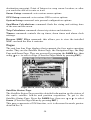
Pub. 988-0151-291
www.lowrance.com
This GPS model is available as a simulator download from this CD or
from the Lowrance web site. To download from the CD select download,
follow the prompts and it will be added to your Start and All programs
list.
LCX-17M
Fish-finding Sonar & Mapping GPS
Extracts of Operation
Instructions
Table of Contents
Section 1: Read Me First!........................................................ 1
Capabilities and Specifications: LCX-17M.................................... 3
How Your Sonar Works ................................................................ 6
How Your GPS Works .................................................................. 7
Introduction to GPS and WAAS................................................... 8
How to use this manual: typographical conventions ................ 11
Section 2: Installation & Accessories.................................. 13
Preparations................................................................................ 13
Transducer Installation.............................................................. 13
Selecting a Transducer Location ............................................ 14
How low should you go? .......................................................... 16
Shoot-thru-hull vs. Transom Mounting ................................. 16
Transom Transducer Assembly And Mounting..................... 17
Trolling motor bracket installation ....................................... 23
Transducer orientation and fish arches................................. 24
Shoot-thru-hull preparation ................................................... 24
Shoot-thru-hull Installation ................................................... 27
Speed/Temperature Sensors ................................................. 29
GPS Antenna/Receiver Module .................................................. 30
Power Connections...................................................................... 33
NMEA 2000 Cable Connections ................................................. 36
Connecting to a NMEA 2000 Network................................... 36
NMEA 0183 Wiring (Data cable) ........................................... 36
Mounting the Unit: Bracket or In-Dash .................................... 38
MMC or SDC Memory Card Installation................................... 42
Other Accessories........................................................................ 43
Face Cover ............................................................................... 45
Section 3: Basic Sonar Operation ....................................... 47
Keyboard ..................................................................................... 47
Power/lights on and off ............................................................... 48
Main Menu .................................................................................. 49
Pages ........................................................................................... 50
Satellite Status Page .............................................................. 50
Navigation Page ...................................................................... 51
Map Page................................................................................. 51
Sonar Page .............................................................................. 52
LCX-17M Sonar Quick Reference .............................................. 55
Sonar Operations ........................................................................ 56
Fish Symbols vs. Full Sonar Chart ........................................ 58
Other Free Training Aids ....................................................... 58
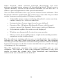
Section 4: Sonar Options & Other Features..................... 61
ASP (Advanced Signal Processing) ..................................... 61
i
Alarms ......................................................................................... 62
Depth Alarms .......................................................................... 62
Zone Alarm .............................................................................. 63
Fish Alarm............................................................................... 64
Calibrate Speed........................................................................... 64
Chart Speed................................................................................. 65
Depth Cursor............................................................................... 66
Depth Range - Automatic ........................................................... 66
Depth Range - Manual ............................................................... 67
Depth Range - Upper and Lower Limits ................................... 67
FasTrack .................................................................................. 69
Fish I.D. (Fish Symbols & Depths) ......................................... 69
FishTrack ................................................................................. 71
Frequency (Change Transducer Frequency) ............................. 72
Grayline ..................................................................................... 73
HyperScroll .............................................................................. 74
Log Sonar Chart Data ................................................................ 74
Noise Rejection............................................................................ 75
Overlay Data ............................................................................... 75
Ping Speed & HyperScroll....................................................... 78
Reset Options .............................................................................. 79
Reset Water Distance ................................................................. 80
Set Keel Offset ............................................................................ 80
Sensitivity & Auto Sensitivity.................................................... 81
Sonar Chart Mode....................................................................... 83
Sonar Page & Sonar Chart Display Options ............................. 83
Full Sonar Chart ..................................................................... 84
Split Zoom Sonar Chart .......................................................... 85
Split Frequency Sonar Chart ................................................. 85
Digital Data/Chart .................................................................. 86
Customize Page Displays ........................................................... 86
FlashGraf ............................................................................. 87
Map With Sonar Split Screen................................................. 88
Sonar Simulator.......................................................................... 89
Stop Chart ................................................................................... 90
Surface Clarity ............................................................................ 91
Upper and Lower Limits ............................................................ 92
Zoom & Zoom Bar ....................................................................... 92
Zoom Pan..................................................................................... 93
Section 5: Sonar Troubleshooting ....................................... 95
Section 6: Basic GPS Operations ......................................... 99
Keyboard ..................................................................................... 99
Power/lights on and off ............................................................. 100
ii
Main Menu ................................................................................ 100
Pages ......................................................................................... 102
Sonar Page ............................................................................ 102
Satellite Status Page ............................................................ 102
Navigation Page .................................................................... 104
Map Page............................................................................... 106
GPS Quick Reference................................................................ 111
Find Your Current Position...................................................... 112
Moving Around the Map: Zoom & Cursor Arrow Keys ........... 112
Selecting Any Map Item With the Cursor ............................... 113
Searching................................................................................... 113
Set a Waypoint.......................................................................... 115
Navigate To a Waypoint ........................................................... 117
Set Man Overboard (MOB) Waypoint...................................... 118
Navigate Back to MOB Waypoint ............................................ 118
Navigate to Cursor Position on Map........................................ 119
Navigate to a Point of Interest................................................. 120
Creating and Saving a Trail..................................................... 121
Displaying a Saved Trail .......................................................... 122
Navigating Trails...................................................................... 123
Visual Trailing ...................................................................... 123
Navigate a Trail (forward).................................................... 123
Navigate a Back Trail (backtrack, or reverse) .................... 126
Transfer Custom Maps and GPS Data Files ........................... 126
Custom Maps: ....................................................................... 126
GPS Data files: ...................................................................... 126
Cancel Navigation..................................................................... 128
Section 7: Advanced GPS Operations ............................... 129
Find Distance From Current Position ..................................... 129
Find Distance From Point to Point .......................................... 129
Icons........................................................................................... 129
Create Icon on Map............................................................... 130
Create Icon at Current Position ........................................... 130
Delete an Icon ....................................................................... 130
Navigate to an Icon ............................................................... 131
Routes........................................................................................ 131
Create and Save a Route ...................................................... 132
PC-created Routes............................................................. 132
Routes Created in the Unit............................................... 132
Delete a Route ....................................................................... 134
Edit a Route .......................................................................... 134
Navigate a Route................................................................... 135
Navigate a Route in Reverse ................................................ 136
iii
Trails ......................................................................................... 137
Delete a Trail ........................................................................ 137
Edit a Trail Name ................................................................. 137
Edit a Trail Color .................................................................. 137
Edit a Trail Pattern .............................................................. 137
Utilities...................................................................................... 138
Alarm Clock........................................................................... 138
Sun/Moon Rise & Set Calculator.......................................... 138
Trip Calculator...................................................................... 138
Trip Down Timer................................................................... 138
Trip Up Timer ....................................................................... 138
Waypoints.................................................................................. 138
Delete a Waypoint................................................................. 138
Edit a Waypoint (Name, Symbol, Position) ......................... 139
Selecting a Waypoint ............................................................ 139
Set a Waypoint by Average Position .................................... 139
Set a Waypoint by Projecting a Position.............................. 140
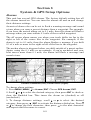
Section 8 System & GPS Setup Options ........................... 141
Alarms ....................................................................................... 141
Auto Satellite Search................................................................ 142
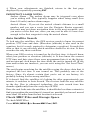
Check MMC Files and Storage Space...................................... 142
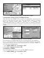
Communications Port Configuration ....................................... 143
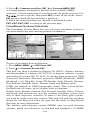
Configure NMEA ...................................................................... 143
Coordinate System Selection.................................................... 144
Map Fix ..................................................................................... 145
Customize Page Displays ......................................................... 147
GPS Simulator .......................................................................... 148
Simulating Trail or Route Navigation ................................. 148
Hide GPS Features ................................................................... 149
Initialize GPS............................................................................ 149
Map Auto Zoom ......................................................................... 150
Map Data................................................................................... 150
Pop-up Map Info.................................................................... 150
Map Boundaries .................................................................... 151
Fill Water With White .......................................................... 151
Map Overlays (Range Rings; Lat/Long Grid) ...................... 151
Map Datum Selection ............................................................... 151
Map Detail Category Selection................................................. 152
Map Orientation ....................................................................... 153
Navionics Charts..................................................................... 154
Port Information ................................................................... 155
Tidal Current Information ................................................... 156
Tide Information ................................................................... 158
iv
Pop-up Help............................................................................... 159
Reset Options ............................................................................ 160
Screen Contrast and Brightness .............................................. 160
Set Language ............................................................................ 161
Set Local Time .......................................................................... 162
Show WAAS Alarm................................................................... 163
Software Version Information.................................................. 163
Sounds and Alarm Sound Styles.............................................. 163
Track Smoothing....................................................................... 164
Trail Options ............................................................................. 165
Delete All Trails .................................................................... 165
Update Trail Option.............................................................. 165
Delete Trail ........................................................................... 166
New Trail............................................................................... 167
Trail Visible/Invisible and Other Trail Options .................. 167
Units of Measure....................................................................... 167
Section 9: Searching ............................................................ 169
Find Addresses.......................................................................... 169
Find Any Item Selected by Map Cursor .................................. 172
Find Interstate Highway Exits ................................................ 172
Find Map Places or Points of Interest (POI) ........................... 175
Find Streets or Intersections.................................................... 176
Find Waypoints......................................................................... 180
Section 10: Supplemental Material ................................... 183
v
Section 3:
Basic Sonar Operation
This section addresses the unit's most basic sonar operations. The
instructions presented in Sec. 3 follow a chronological order. Sec. 4,
Sonar Options & Other Features, will discuss other more advanced
functions and utilities. Material in Sec. 4 is arranged in alphabetical
order.
Before you turn on the unit, it's a good idea to learn about the different
keys, the Main Menu, the four Page screens and how they all work
together. BUT, if you just can't wait to get on the water, turn to the
one-page Quick Reference on page 55.
Keyboard
4
8
9
2
7
3
6
5
1
MMC drawer
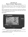
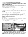
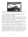
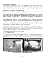
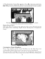
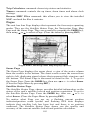
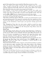
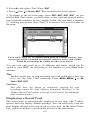
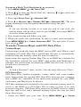
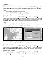
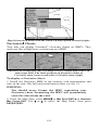
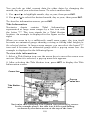
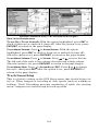
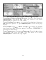
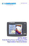
LCX-17M sonar/GPS unit, front view, showing sonar screen, keyboard
and access door for the MMC compartment.
1. PWR/LIGHT (Power & Light) – The PWR key turns the unit on and
off and activates the backlight.
47
2. PAGES – Pressing this and the ← → arrow keys switches the unit
between the four different page screens. (Satellite Status Page,
Navigation Page, Map Page and Sonar Page.) Each page represents one
of the unit's major operation modes.
3. MENU – Press this key to show the menus and submenus, which
allow you to select a command or adjust a feature. This also accesses
search functions for streets, intersections, addresses and highway exits.
4. ARROW KEYS – These keys are used to navigate through the
menus, make menu selections, enter data and move the map and sonar
chart cursors.
5. ENT/ICONS (Enter & Icons) – This key allows you to save data,
accept values or execute menu commands. It is also used to create
event marker icons.
6. EXIT – The Exit key lets you return to the previous screen, clear
data and close menus.
7. WPT – (Waypoint) The Waypoint key is used to save and recall
waypoints, search for waypoints and access the waypoint list. It also
launches the Point-of-Interest (POI) search menus and is involved in
some navigation functions.
8. ZOUT – (Zoom Out) – This key lets you zoom the screen out. On the
Sonar Page, this key returns you to a full sonar chart display, showing
the entire water column from surface to bottom. On the Map Page, this
lets you see a larger geographic area on the map. Less detail is seen as
you zoom out.
9. ZIN – (Zoom In) – This key lets you zoom the screen in. On the Sonar
Page, this key enlarges fish signals and bottom detail. On the Map
Page, zooming in lets you see greater detail in a smaller geographic
area on the map.
Power/lights on and off
To turn on the unit, press PWR. As the unit powers up, the Map Page is
displayed first. To switch to the Sonar Page, press PAGES|→|EXIT.
To turn on the backlight, press PWR again. The unit has three backlight
levels to select from. Repeatedly pressing PWR will cycle through the
backlight settings and turn off the backlight.
Turn off the unit by pressing and holding the PWR key for 3 seconds.
48
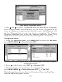
Main Menu
The unit has a Main Menu, which contains some function commands
and some setup option commands. The instructions in this section will
deal only with sonar functions, the basic commands that make the unit
show sonar signals on your screen. This unit will work fine right out of
the box with the factory default settings. But, if you want to learn
about the various sonar options, see Sec. 4, Sonar Options & Other
Features. (For general system setup and GPS options, see Sec. 8,
System Setup and GPS Setup Options.)
You can access the Main Menu from any of the four Page screens by
pressing MENU|MENU. To clear the menu screen and return to the page
display, press EXIT. (Remember, our text style for "MENU|MENU" means
"press the Menu key twice." See a full explanation of our instruction
text formatting on page 11, Instructions = Menu Sequences.)
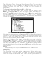
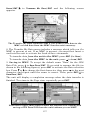
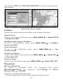
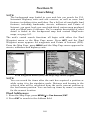
Main Menu.
The Main Menu commands and their functions are:
Screen command: changes the contrast or brightness of the display
screen.
Sounds command: enables or disables the sounds for key strokes and
alarms and sets the alarm style.
Alarms command: turns GPS alarms on or off and changes alarm
thresholds.
Route Planning command: used to plan, view or navigate a route.
My Trails command: shows, creates and deletes plot trails. Also used
to navigate or backtrack a trail.
Cancel Navigation command: turns off the various navigation
commands. Used to stop navigating after you have reached your
49
destination waypoint, Point of Interest or map cursor location; or after
you reach the end of a route or trail.
Sonar Setup command: sets various sonar options.
GPS Setup command: sets various GPS receiver options.
System Setup command: sets general configuration options.
Sun/Moon Calculations command: finds the rising and setting time
of the sun and the moon.
Trip Calculator command: shows trip status and statistics.
Timers command: controls the up timer, down timer and alarm clock
settings.
Browse MMC Files command: this allows you to view the installed
MMC card and the files it contains.
Pages
The unit has four Page displays that represent the four major operating
modes. They are the Satellite Status Page, the Navigation Page, the Map
Page and Sonar Page. They are accessed by pressing the PAGES key, then
using → or ← to select a Page. (Clear the Pages Menu by pressing EXIT.)
Pages Menu, showing sonar display options.
Satellite Status Page
The Satellite Status Page provides detailed information on the status of
the unit's satellite lock-on and position acquisition. To get to the
Satellite Status Page: Press the PAGES key, then use → or ← to select
STATUS. (Clear the Pages Menu by pressing EXIT.)
This page represents a GPS function, so it is discussed in much greater
detail in Sec. 6.
50
No matter what Page you are on, a flashing current position
indicator/question mark symbol and flashing GPS data displays
indicate that satellite lock has been lost and there is no position
confirmed.
WARNING:
Do not begin navigating with this unit until the numbers
have stopped flashing!
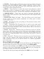
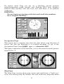
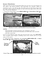
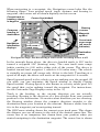
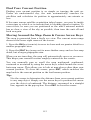
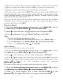
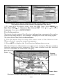
Satellite Status Page.
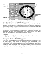
Navigation Page
This screen has a compass rose that not only shows your direction of
travel, but also the direction to a recalled waypoint. To get to the
Navigation Page: Press PAGES| → or ← to NAVIGATION|EXIT.
This page represents a GPS function, so it is discussed in much greater
detail in Sec. 6.
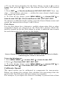
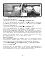
The Navigation Page (left); navigation with sonar (right).
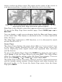
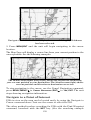
Map Page
The Map Page screens show your course and track from a "bird's-eye"
view, on a moving map. By default, this unit shows the map with north
51
always at the top of the screen. The arrow in the center of the screen is
your present position. It points in the direction you're traveling.
Map Page, showing position on Bull Shoals Lake, Arkansas. The full
map option (left). Map with sonar option (right).
Map Page is the default screen that appears when you turn on the unit.
To get to the Map Page from another page: Press PAGES| → or ← to
MAP|EXIT.
You can display a split screen showing both the Map and Sonar pages
at the same time. This feature is discussed in Sec. 4, Sonar Options &
Other Features.
The Map Page represents a GPS function, so it is discussed in much
greater detail in Sec. 6.
Sonar Page
The Sonar Page displays the sonar chart. This is a "cross-section" view
of the water column beneath the boat. The chart moves across the
screen, displaying sonar signal echoes that represent fish, structure
and the bottom.
To get to the Sonar Page: Press the PAGES key, then use → or ← to
select SONAR. (Clear the Pages Menu by pressing EXIT.) The Pages Menu
offers five chart display options under the Sonar Page category. To access
them, press PAGES|← or→ to SONAR|↓ to Option Name|EXIT.
The Sonar Page has its own menu, which is used for advanced functions
and for setting various options. (Sonar Options and other features are
discussed in Sec. 4.) To Access the Sonar Page menu, from the Sonar
Page press MENU.
52
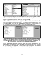
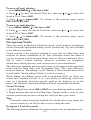
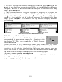
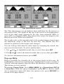
Pages Menu, showing sonar chart display option commands (left).
Sonar Page in full sonar chart display mode (right).
Sonar chart display options (from left) split zoom and split frequency.
Sonar chart display options (from left) digital data and FlashGraf.
53
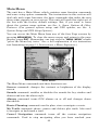
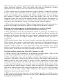
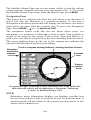
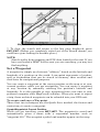
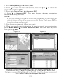
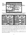
Sonar Page Menu. Most of these functions are discussed in Sec. 4.
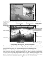
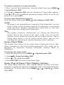
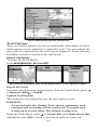
Digital data
Surface clutter
Surface signal
overlay
Depth scale
(depth &
temperature)
In FasTrack, fish
arches show as
horizontal bars.
Fish arches
Zoom bar
Structure
Bottom signal
FasTrack
bar graph
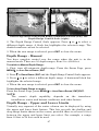
Sonar Page, showing full sonar chart mode.
You can customize how the Sonar Page displays its pictures and other data
in many ways. Your unit also includes several special sonar features and
options that can help you better interpret the underwater scene.
We'll discuss all of those features and options in Sec. 4, but to show you
how easy the unit is to operate, the following page contains a simplified,
10-step quick reference that will cover most fish finding situations. The
quick reference describes how your unit will operate with all the sonar
features in their automatic modes, which are set at the factory.
54
LCX-17M Sonar Quick Reference
1. Mount the transducer, antenna and unit. Connect the unit to electric
power and the transducer. (If GPS operation is desired, connect GPS
antenna, too.) Make sure the MMC is in. (See complete installation
details beginning on page 13.)
2. Launch your boat.
3. To turn on the unit, press and release PWR key.
4. Opening screen displays Map Page. Rotate through the four main
Page screens (Map Page, Satellite Status Page, Navigation Page, Sonar
Page) by pressing PAGES|← or → to select Page Name|EXIT. Switch
Pages to display Sonar Page.
5. If GPS data is desired, wait while unit locates satellites and calculates
current position. When the unit acquires position, a tone sounds and a
position acquired message appears.
6. With position acquired (if desired), head for your fishing grounds.
Your unit will automatically display digital depth and surface water
temperature in the top left corner of the screen.
The auto settings will track the bottom, displaying it in the lower
portion of the screen. The full sonar chart will scroll from right to left,
showing you what's under the boat as you cruise across the water. You
can change the display by:
Zoom in to enlarge the chart for more detail: press ZIN.
Zoom out to return to full chart mode: press ZOUT.
7. Watch the display for the appearance of fish arches. When you see
arches, you've found fish! Stop the boat and get your lure or bait into
the water at the depth indicated on the sonar chart.
8. Gauge the fish depth by visually comparing the fish arches with the
depth scale on the right side of the screen, or get a more accurate
measure with the Depth Cursor. Press MENU|↓ to DEPTH CURSOR|ENT.
Press ↓ to align the cursor line with the fish arch. The exact depth
appears in a box at the right end of the cursor line. To clear the cursor,
press EXIT.
9. If you are drifting at a very low speed or anchored, you are not
moving fast enough for a fish to return the tell-tale fish arch signal. As
you drift over a fish, or as a fish swims through the transducer's signal
cone, the fish echo will appear as a straight line suspended between the
surface and the bottom.
10. To turn off the unit, press and hold PWR key for three seconds.
55
Sonar Operations
As you can see from the quick reference on the previous page, basic operation
is pretty easy, right out of the box. If you are a sonar novice, try operating the
unit with the factory defaults until you get a feel for how it's working.
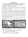
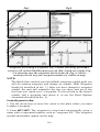
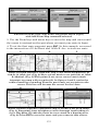
As you're learning the basics, there is one setting you might want to tinker
with from time to time — Sensitivity.
Sensitivity controls the unit's ability to pick up echoes. If you want to see
more detail, try increasing the sensitivity, a little at a time. There are
situations when too much clutter appears on the screen. Decreasing the
sensitivity can reduce the clutter and show the strongest fish echoes, if fish
are present. As you change the sensitivity setting, you can see the difference
on the chart as it scrolls.
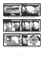
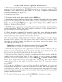
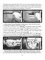
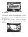
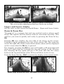
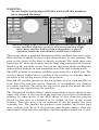
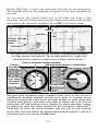
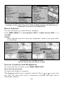
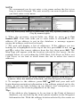
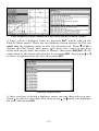
Fig. 1
Fig. 2
Fig. 3
Fig. 4
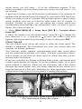
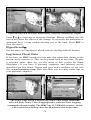
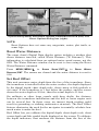
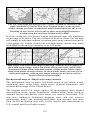
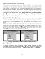
These figures show results of different sensitivity levels on the same
location. Fig. 1: Sensitivity at 88 percent. Typical of full auto mode. Fig.
2: Sensitivity set at 75 percent. Fig. 3: Sensitivity set at 50 percent. Fig.
4: Sensitivity set at 100 percent.
You can change the sensitivity level whether you are in Auto
Sensitivity mode or Manual Sensitivity mode. The adjustment method
works the same in both modes, but gives you slightly different results.
56
Adjusting sensitivity in Auto Sensitivity Mode is similar to manually
adjusting a car's speed with the accelerator pedal while cruise control is
on. You can tell the car to run faster, but when you let off the gas the
cruise control automatically keeps you from running slower than the
minimum speed setting. In this unit, auto mode will let you increase
sensitivity to 100 percent, but the unit will limit your minimum setting.
This prevents you from turning sensitivity down too low to allow
automatic bottom tracking. When you change the setting with auto
turned on, the unit will continue to track the bottom and make minor
adjustments to the sensitivity level, with a bias toward the setting you
selected.
Adjusting sensitivity in Manual Sensitivity Mode is similar to driving a
car without cruise control — you have complete manual control of the
car's speed. In this unit, manual mode allows you to set sensitivity at
100 percent (maximum) or zero percent (minimum.) Depending on
water conditions, the bottom signal may completely disappear from the
screen when you reduce sensitivity to about 50 percent or less!
Try adjusting sensitivity in both auto and manual modes to see how
they work.
To adjust sensitivity:
1. Press MENU|ENT.
2. The Sensitivity Control Bar appears. Press ↓ to decrease sensitivity;
press ↑ to increase sensitivity. When it's set at the desired level, press
EXIT. (When you reach the maximum or minimum limit, a tone sounds.)
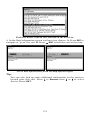
Sonar Menu with Sensitivity command selected (left). The Sensitivity
Control Bar (right).
NOTE:
If you want to change the sensitivity in Manual Mode, first turn off
Auto Sensitivity: from the Sonar Page, press MENU|↓ to AUTO
SENSITIVITY|ENT|↑ to SENSITIVITY|ENT. Press ↓ or ↑ to pick a different
sensitivity setting. When it's set at the desired level, press EXIT.
57
Important Tip:
While you are experimenting and learning, it's possible to scramble
the settings so that the sonar picture disappears from your screen.
If that happens, remember that it's easy to switch back to full
automatic operation by simply restoring the factory auto settings.
Here's how:
To Restore Factory Settings
1. Press MENU|MENU|↓ to SYSTEM SETUP|ENT|↓ to RESET OPTIONS|ENT.
2. The unit asks if you want to reset all the options. Press ← to
YES|ENT. All options are reset, and the unit reverts back to the Map
Page at the 4000-mile zoom range. (Any recorded sonar logs or GPS
data will be unchanged.)
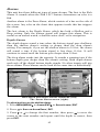
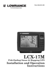
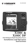
Fish Symbols vs. Full Sonar Chart
You may have noticed in the quick reference that we used fish arches in
full sonar chart mode for our example, and not the popular Fish I.D.
fish symbol feature. Here's why.
Fish I.D. is an easier way for a sonar novice to recognize a fish signal
return when he sees it. However, locating a fish via symbol has some
limitations.
Your sonar unit's microprocessor is remarkably powerful, but it can be
fooled. Some of the echoes calculated to be fish could be tree limbs or
turtles! To see what's under your boat in maximum detail, we
recommend you turn off Fish I.D. and begin learning to interpret fish
arches.
Fish I.D. is most handy when you're in another part of the boat or
performing some task that prevents you from watching the sonar
screen. Then, you can turn on Fish I.D. and the audible fish alarm.
When that lunker swims under your boat, you'll hear it!
Fish I.D. can also be useful when you want to screen out some of the
sonar detail gathered by your unit. For example, in one case, fisherman
in San Francisco Bay saw clouds of clutter in the water but no fish
arches. When a downrigger was pulled up, it brought up several small
jellyfish. The fisherman switched their Lowrance sonar to Fish I.D.,
which screened out the schools of jellyfish and clearly showed the game
fish there as fish symbols.
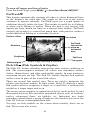
Other Free Training Aids
The sonar options section discusses Fish I.D., fish alarms and other
features in greater detail. If you or a friend has Internet access, you can
also learn more about interpreting what you see on your sonar screen.
Visit our web site, www.lowrance.com. Be sure to check out the free
58
Sonar Tutorial, which includes animated illustrations and more
pictures of actual sonar returns, all described in detail. There's even a
"printer friendly" version of the tutorial available on our web site…it
makes a great supplement to this operation manual!
You can also download a free copy of our Sonar Viewer software. This
PC-based software application plays back any sonar chart log recorded
with a Lowrance sonar product. Features include:
•
Adjustable range, zoom, sensitivity, Grayline , noise rejection,
surface clarity, etc. of the recorded file.
•
Interpretation of sonar signals can be user defined.
•
Operates like a Windows Multimedia Player with forward,
reverse, pause, fast forward, fast reverse, and scroll buttons.
•
Adjustments update the entire record displayed
•
Window can dynamically be sized on your monitor.
•
Mouse cursor shows GPS position, depth and sounding number
anywhere on the visible record.
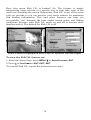
For the ultimate training aid, be sure to download the free emulator
software for your unit. Aside from being just plain fun, this program
can help you learn both basic and advanced operations without burning
boat fuel! Lowrance is the first sonar manufacturer to provide this type
of training tool for customers.
This PC application simulates the actual sonar/GPS unit on your
computer. You can run it from your computer keyboard or use your
mouse to press the virtual keys. Easy download and installation
instructions are available on our web site.
59
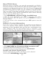
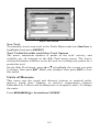
A free training emulator is available for your unit on our web site.
The emulator works exactly like your real sonar/GPS unit. Using the
Sonar Simulator and GPS Simulator features, it allows you to play
back sonar logs, run GPS routes and trails, even create real waypoints
you can use in the field! You can even take snapshots of the Sonar
Chart and print them or e-mail them to friends.
60
Section 4:
Sonar Options & Other Features
Material in this section is arranged in alphabetical order.
ASP (Advanced Signal Processing)
The ASP feature is a noise rejection system built into the sonar unit
that constantly evaluates the effects of boat speed, water conditions
and interference. This automatic feature gives you the best display
possible under most conditions.
The ASP feature is an effective tool in combating noise. In sonar terms,
noise is any undesired signal. It is caused by electrical and mechanical
sources such as bilge pumps, engine ignition systems and wiring, air
bubbles passing over the face of the transducer, even vibration from the
engine. In all cases, noise can produce unwanted marks on the display.
The ASP feature has four settings — Off, Low, Medium and High. If
you have high noise levels, try using the "High" ASP setting. However,
if you are having trouble with noise, we suggest that you take steps to
find the interference source and fix it, rather than continually using the
unit with the high ASP setting.
There are times when you may want to turn the ASP feature off. This
allows you to view all incoming echoes before they are processed by the
ASP feature.
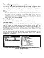
Sonar Menu with Sonar Features selected (left). The Sonar Features
menu (right), Noise Rejection selected with ASP at default low setting.
To change the ASP level:
1. From the Sonar Page, press MENU|↓ to SONAR FEATURES|ENT.
2. Press → then ↓ to NOISE REJECTION|ENT.
3. Press ↓ or ↑ to select a setting, then press ENT.
4. To return to the previous page, press EXIT|EXIT.
61
Alarms
This unit has three different types of sonar alarms. The first is the Fish
Alarm. It sounds when the Fish I.D. feature determines an echo is a
fish.
Another alarm is the Zone Alarm, which consists of a bar on the side of
the screen. Any echo on the chart that appears inside this bar triggers
the alarm.
The last alarm is the Depth Alarm, which has both a Shallow and a
Deep setting. Only the bottom signal will trigger this alarm. This is
useful as an anchor watch, a shallow water alert, or for navigation.
Depth Alarms
The depth alarms sound a tone when the bottom signal goes shallower
than the shallow alarm's setting or deeper than the deep alarm's
setting. For example, if you set the shallow alarm to 10 feet, the alarm
will sound a tone if the bottom signal is less than 10 feet. It will
continue to sound until the bottom goes deeper than 10 feet.
The deep alarm works just the opposite. It sounds a warning tone if the
bottom depth goes deeper than the alarm's setting. Both depth alarms
work only off the digital bottom depth signals. No other targets will trip
these alarms. These alarms can be used at the same time or individually.
Main Menu and Sonar Alarms command (left);
The Sonar Alarms menu (right).
To adjust and turn on the shallow alarm:
1. Press MENU|MENU|↓ to ALARMS|ENT|↓ to SONAR ALARMS|ENT.
2. Press → to SHALLOW ALARM DEPTH|ENT.
3. Press ↑ or ↓ to change the first number, then press → to move the
cursor to the next number and repeat until the depth is correct, then
press ENT.
62
4. Press ← to SHALLOW ALARM ENABLED|ENT|EXIT|EXIT|EXIT.
5. To turn off the alarm, press MENU|MENU|↓ to ALARMS|ENT|↓ to SONAR
ALARMS|ENT|ENT|EXIT|EXIT|EXIT.
To switch to a different depth setting, open the Sonar Alarms menu and
repeat the instructions in step 3 above.
To adjust and turn on the deep alarm:
1. Press MENU|MENU|↓ to ALARMS|ENT|↓ to SONAR ALARMS|ENT.
2. Press ↓ to DEEP ALARM ENABLED|→ to DEEP ALARM DEPTH|ENT.
3. Press ↑ or ↓ to change the first number, then press → to move the
cursor to the next number and repeat until the depth is correct, then
press ENT.
4. Press ← to DEEP ALARM ENABLED|ENT|EXIT|EXIT|EXIT.
5. To turn off the alarm, press MENU|MENU|↓ to ALARMS|ENT|↓ to
SONAR ALARMS|ENT|↓ to DEEP ALARM ENABLED|ENT|EXIT|EXIT|EXIT.
To switch to a different depth setting, open the Sonar Alarms menu and
repeat the instructions in step 3 above.
Zone Alarm
The zone alarm is triggered when any echo passes inside the zone
alarm bar, shown on the right side of the screen.
To adjust and turn on the zone alarm:
1. Press MENU|MENU|↓ to ALARMS|ENT|↓ to SONAR ALARMS|ENT.
2. Press ↓ to ZONE ALARM ENABLED|→ to ADJUST ZONE|ENT.
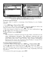
Sonar Alarms menu, with Adjust Zone command selected (left); Adjust
Zone Alarm selection box, with Upper Limit selected (right).
3. To set the upper boundary for the Zone Alarm, use ← or→ to select
UPPER, then press ↑ or ↓ to move the top of the bar to the desired depth.
63
4. To set the lower boundary for the Zone Alarm, use ← or→ to select
LOWER, then press ↑ or ↓ to move the bottom of the bar to the desired
depth.
5. Press EXIT|← to ZONE ALARM ENABLED|ENT|EXIT|EXIT|EXIT. Now, any
echo — fish, bottom, structure — within the zone alarm's depth range
will trigger the zone alarm.
6. To turn off the alarm, press MENU|MENU|↓ to ALARMS|ENT|↓ to
SONAR ALARMS|ENT|↓ to ZONE ALARM ENABLED|ENT|EXIT|EXIT|EXIT.
To switch to a different depth setting, open the Sonar Alarms menu and
repeat the instructions in steps 3 and 4 above.
Fish Alarm
Use the fish alarm for a distinctive audible alarm when fish or other
suspended objects are detected by the Fish I.D. feature (Fish I.D.
must be turned on for the Fish Alarm to work). A different tone sounds
for each fish symbol size shown on the display.
Sonar Alarms menu with Fish Alarm selected. The checkbox is blank,
indicating the alarm is turned off.
To turn the fish alarm on:
1. Press MENU|MENU|↓ to ALARMS|ENT|↓ to SONAR ALARMS|ENT.
2. Press ↓ to FISH ALARM|ENT|EXIT|EXIT|EXIT.
3. To turn off the alarm, press MENU|MENU|↓ to ALARMS|ENT|↓ to
SONAR ALARMS|ENT|↓ to FISH ALARM|ENT|EXIT|EXIT|EXIT.
Calibrate Speed
The speed sensor can be calibrated to compensate for inaccuracies.
Before you change the setting, first calculate the percentage that the
speed is off. You will enter this percentage in a moment.
For example, if you figure the sensor is reading 10 percent faster than
64
actual speed, you will enter – 10 in the calibration window. If the
sensor is reading 5 percent slower than true speed, you will enter + 5 in
the window.
A good way to gauge your speed sensor's performance is to compare its
reading with the ground speed measured by your unit's GPS functions.
When you make a run to compare GPS ground speed to speed sensor
speed, perform your test in relatively calm water free of current, if
possible. (Unless, of course, you are taking the current speed into
consideration when making your calculation.) After you have a correct
figure, here's how to enter it:
1. Press MENU|MENU|↓ to SONAR SETUP|ENT|↓ to CALIBRATE WATER
SPEED|ENT.
2. Enter the number you calculated earlier: press ↑ or ↓ to change the
first character (+ or –), then press → to move the cursor to the next
number and repeat until the percentage is correct, then press EXIT.
Chart Speed
The rate echoes scroll across the screen is called the chart speed. The
default is maximum. We recommend you leave the setting there for
virtually all fishing conditions.
You, however, might consider experimenting with chart speed when
you are stationary or drifting very slowly. You may sometimes achieve
better images as you slow the chart speed to match how fast you are
moving across the bottom.
If you are at anchor, ice fishing or fishing from a dock, experiment with
a chart speed around 50 percent. If you are drifting slowly, try a chart
speed around 75 percent. When you are stationary and a fish swims
through the sonar signal cone, the image appears on the screen as a
long line instead of a fish arch. Reducing the chart speed may result in
a shorter line that more closely resembles a regular fish return.
Sonar Page menu with Chart Speed command selected (left);.
The Chart Speed Control Bar (right).
65
If you do experiment with chart speed, remember to reset it to
maximum when you resume trolling or moving across the water at
higher speed. To change chart speed:
1. From the Sonar Page, press MENU|↓ to CHART SPEED|ENT.
2. The Chart Speed Control Bar appears. Press ↓ to decrease chart
speed; press ↑ to increase chart speed.
3. When it's set at the desired level, press EXIT.
Depth Cursor
The depth cursor consists of a horizontal line with a digital depth box on
the right side. The numbers inside the box show the depth of the cursor.
Cursor line
Depth box
Sonar Page menu with Depth Cursor command selected (left). Sonar
chart with the depth cursor active (right). The line indicates the large
fish is 21.95 feet deep.
The cursor can be moved to any location on the screen, letting you
pinpoint the depth of a target.
1. From the Sonar Page, press MENU|↓ to DEPTH CURSOR|ENT.
2. The depth cursor appears. Press ↓ to lower the cursor line; press ↑ to
raise the cursor line.
3. To clear the depth cursor, press EXIT.
Depth Range - Automatic
When turned on for the first time, the bottom signal is automatically
placed in the lower half of the screen. This is called Auto Ranging and
is part of the automatic function. You can change the range to a
different depth, depending upon the bottom depth and the current
range. To do this:
1. From the Sonar Page, press MENU|↓ to DEPTH RANGE|ENT.
66
Sonar Page menu with Depth Range command selected (left); The
Depth Range Control Scale (right).
2. The Depth Range Control Scale appears. Press ↑ or ↓ to select a
different depth range. A black bar highlights the selected range. The
shaded numbers can not be selected.
3. When the new range is selected, press EXIT to clear the menu.
Depth Range - Manual
You have complete control over the range when the unit is in the
manual mode. There are 16 depth ranges, from 5 to 4,000 feet.
To switch to Manual Depth Range:
1. First, turn off automatic depth range. From the Sonar Page, press
MENU|↓ to AUTO DEPTH RANGE|ENT.
2. Press ↑ to DEPTH RANGE|ENT and the Depth Range Control Scale appears.
3. Press ↓ or ↑ to select a different depth range. A horizontal black bar
highlights the selected range.
4. When the new range is selected, press EXIT to clear the menu.
To turn Auto Depth Range on again:
From the Sonar Page, press MENU|↓ to AUTO DEPTH RANGE|ENT|EXIT.
NOTE:
The sonar's depth capability depends on the transducer
installation, water and bottom conditions, and other factors.
Depth Range - Upper and Lower Limits
Virtually any segment of the water column can be displayed by using
the upper and lower limit feature. This lets you pick the shallow and
deep range limits shown on the screen, provided there is at least 10 feet
between the upper and lower limit you select. For example, a range
from 12 feet to 34 feet could be used.
67
Changing the upper and lower limits gives you far greater control over
the depth range. This feature lets you "zoom in" the display in almost
unlimited combinations. Nearly any segment of the water column, from
the surface to the bottom can be shown. This enlarges the sonar targets
to best suit your fishing needs and water conditions.
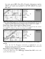
Sonar Page Menu with Upper and Lower Limits command selected
(left); Sonar Chart Limits menu, with Upper Limit selected (right).
To change the upper and lower limits:
1. From the Sonar Page, press MENU|↓ to UPPER AND LOWER LIMITS|ENT.
The Sonar Chart Limits menu appears, with Upper Limit selected.
2. To set the upper limit, press ENT. Press ↑ or ↓ to change the first
number, then press → to move the cursor to the next number and
repeat until the depth is correct, then press EXIT.
3. To set the lower limit, press ↓ to LOWER LIMIT|ENT. Press ↑ or ↓ to
change the first number, then press → to move the cursor to the next
number and repeat until the depth is correct, then press EXIT|EXIT|EXIT.
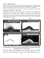
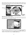
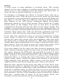
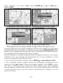
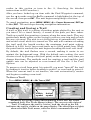
Fish arches
Area "zoomed"
Normal display, in auto depth range mode, (left); Display "zoomed" with
Upper and Lower Limits focusing on the portion of the water column
from 25 feet to 45 feet deep (right). In the "zoomed" image on the right,
note the target definition, showing two fish holding just off the structure.
68
To turn off upper and lower limits:
From the Sonar Page, press MENU|↓ to AUTO DEPTH RANGE|ENT|EXIT.
FasTrack
This feature automatically converts all echoes to short horizontal lines
on the display's far right side. The graph on the rest of the screen
continues to operate normally. FasTrack gives you a rapid update of
conditions directly under the boat. This makes it useful for ice fishing,
or when you're fishing at anchor. When the boat is not moving, fish
signals are long, drawn out lines on a normal chart display. FasTrack
converts the graph to a vertical bar graph that, with practice, makes a
useful addition to fishing at a stationary location.
Surface clutter
Fish arches
FasTrack,
fish arches
show as
horizontal
bars.
Structure
Grayline
Bottom signal
FasTrack
bar graph
Sonar Page showing FasTrack.
Fish I.D. (Fish Symbols & Depths)
The Fish I.D. feature identifies targets that meet certain conditions as
fish. The microcomputer analyzes all echoes and eliminates surface
clutter, thermoclines, and other undesirable signals. In most instances,
remaining targets are fish. The Fish I.D. feature displays fish symbols
on the screen in place of the actual fish echoes.
There are several fish symbol sizes. These are used to designate the
relative size between targets. In other words, Fish I.D. displays a small
fish symbol when it recognizes a target as a small fish, a medium fish
symbol on a larger target and so on.
The sonar's microcomputer is sophisticated, but it can be fooled. It can't
distinguish between fish and other suspended objects such as trotlines,
turtles, submerged floats, air bubbles, etc. Individual tree limbs
extending outward from a group of limbs are the hardest objects for the
Fish I.D. feature to distinguish from fish.
You may see fish symbols on the screen when actually, there are no
fish. The reverse also is true.
69
Does that mean Fish I.D. is broken? No. The feature is simply
interpreting sonar returns in a specific way to help take some of the
work out of reading the screen. Remember: Fish I.D. is one of the many
tools we provide so you can analyze your sonar returns for maximum
fish finding information. This and other features can help you
successfully "see" beneath the boat under varied water and fishing
conditions. Practice with Fish I.D. mode on and off to become more
familiar with it. The default for Fish I.D. is off.
Sonar Features highlighted (left); Fish I.D. Symbols selected (right).
To turn the Fish I.D. feature on:
1. From the Sonar Page, press MENU|↓ to SONAR FEATURES|ENT.
2. Press ↓ to FISH SYMBOLS|ENT|EXIT|EXIT.
To turn off Fish I.D., repeat the instructions in step 1.
70
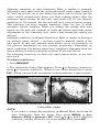
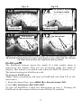
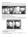
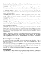
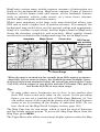
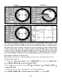
Fig. 1 B
Fig. 1 A
Fish symbols appear
in surface clutter
Many fish
arches visible
Fewer fish
symbols visible
Fig. 2 B
Fig. 2 A
No fish shown
Fish arches
above structure
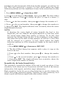
Figures 1A and 2A (left) show Sonar Page in normal chart mode. Figures
1B and 2B (right) show the same underwater scene with Fish I.D. turned
on. Note how arches are replaced with symbols.
FishTrack
The FishTrack feature shows the depth of a fish symbol when it
appears on the display. This lets you accurately gauge the depth of
targets. This feature is available only when the Fish I.D. feature is on.
The default setting for FishTrack is off.
To turn on FishTrack:
(Note: These instructions will turn on FishTrack and Fish I.D. at the
same time.)
1. From the Sonar Page, press MENU|↓ to SONAR FEATURES|ENT.
2. Press ↓ to FISH DEPTHS|ENT|EXIT|EXIT.
To turn off FishTrack, repeat the instructions in step 1. Turning off
FishTrack in this manner will not turn off Fish I.D. symbols.
71
Symbols with
FishTrack depths
Sonar Features menu with Fish I.D. Depths selected (left). When the
check box to the left is unchecked, the feature is off. Sonar Page
showing Fish I.D. symbols and FishTrack depths turned on (right).
Frequency (Change Transducer Frequency)
(Dual-Frequency Transducers only)
A dual-frequency transducer operates with both 200 kHz and 50 kHz.
The 200 kHz frequency has a 12° cone angle and the 50 kHz frequency
has a 35° cone angle.
The default frequency is 200 kHz, which is best for use in shallow water
(about 300 feet or less). This frequency is the best choice for about 80
percent of the fresh and salt water sport fishing applications. When you
get into very deep salt water, 300 to 500 feet or deeper, the 50 kHz
frequency is the best choice.
The 200 kHz transducer will give you better detail and definition, but
less depth penetration. The 50 kHz transducer will give you greater
depth penetration, but a little less detail and less definition. (Remember,
all sonar units typically read deeper in fresh water than in salt water.)
There is a common exception to these rules of thumb. Some fishermen
on freshwater lakes (or the ocean) using downriggers like to see them
on the sonar. In many of those cases, you'll see a 50 kHz transducer
frequency in use because the wider cone angle lets them watch the bait.
72
Sonar Features menu with a frequency of 200 kHz selected.
To change the frequency setting to 50 kHz:
1. From the Sonar Page, press MENU|↓ to SONAR FEATURES|ENT.
2. Press ↓ to 50 KHZ|ENT.
3. Press EXIT|EXIT to clear the menu.
To change the frequency setting to 200 kHz:
1. From the Sonar Page, press MENU|↓ to SONAR FEATURES|ENT.
2. Press ↓ to 200 KHZ|ENT.
3. Press EXIT|EXIT to clear the menu.
Grayline
Grayline lets you distinguish between strong and weak echoes. It
"paints" gray on targets that are stronger than a preset value. This
allows you to tell the difference between a hard and soft bottom. For
example, a soft, muddy or weedy bottom returns a weaker signal which
is shown with a narrow or no gray line. A hard bottom returns a strong
signal which causes a wide gray line.
If you have two signals of equal size, one with gray and the other
without, then the target with gray is the stronger signal. This helps
distinguish weeds from trees on the bottom, or fish from structure.
Grayline is adjustable. The factory default for this unit is 69 percent.
Since Grayline shows the difference between strong and weak signals,
adjusting the sensitivity may also require a different Grayline level.
The level chosen by the sonar unit at power on is usually adequate for
most conditions. Experiment with your unit to find the Grayline setting
that's best for you.
From a sonar page, press MENU|↓, select GRAYLINE, then press|ENT.
73
Grayline selected on sonar menu (left); Grayline control bar (right).
Press ↑ or ↓ to increase or decrease Grayline. Echoes scrolling onto the
screen will show the effects of the change. If you reach the maximum or
minimum level, a tone sounds alerting you to the limit. Press EXIT to
clear the menu.
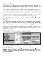
HyperScroll
See the entry on Ping Speed, which controls the HyperScroll feature.
Log Sonar Chart Data
If you have an MMC installed in the unit, the sonar data shown on the
screen can be saved to it. This can be played back at any time. (To play
a recorded sonar chart log, see the entry in this section for Sonar
Simulator.) If you have a personal computer and internet access,
download our free Sonar Viewer and your unit’s emulator at our web
site, www.lowrance.com. That will allow you to replay sonar logs on
your personal computer.
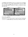
The Sonar Page menu with the Log Sonar Chart Data command
selected (left). Sonar Chart Logging menu, with the Start Logging
command selected (right). The MMC has 11.7 MB of free space, which
will record the scrolling chart for 20 minutes and 44 seconds.
74
To record or log chart data:
1. Press MENU|↓ to LOG SONAR CHART DATA|ENT.
2. To record data using the default settings, press ENT. The menu clears
and the Sonar Page title bar shows the name of the file you are
recording. Warning messages will appear as recording time begins to run
out.
NOTE:
You can change any of the settings by using the cursor arrows to
highlight different commands. Select FILE NAME if you want to
change the name. Select CHART QUALITY if you want to lower the file
quality and record for a longer period of time. After you've changed
the settings, select START LOGGING.
Noise Rejection
See the entry on Advanced Signal Processing in this section.
Overlay Data
On any page display except the Satellite Status and Navigation pages,
you can "float" or overlay additional data on the screen with the
Overlay Data command. The various data available from your unit are
divided into categories in the Overlay Data menu. These categories
include GPS Data, Navigation, Trip Calculator, Time, Sonar Data and
Miscellaneous Data.
You can select items from any of these categories for display, in any
combination. The category divisions are there only to help you sort
through the information.
Overlay Data Shown window (left); Data viewer with the Sonar Data
category expanded (right).
75
To overlay information on your screen:
1. Press MENU|↓ to OVERLAY DATA|ENT.
2. If you have overlay data on your display, you’ll see a list of that data
on the overlay data shown menu. To add data select (ENT TO ADD) and
press ENT. The data viewer shows information categories with "+" or "–"
symbols next to each category name. A category with a "+" next to it is
expandable, meaning its contents are hidden.
Selecting the category name and pressing ENT will show the category's
contents, so you can choose items within it. An expanded category (one
with a "–" next to its name) can be collapsed to hide its contents. Just
select the category and press ENT.
3. Expand any categories that might contain data you want to display.
Then press ↓ or ↑ to select a data option.
4. With the data option highlighted, press ENT to check it (turn it on) or
uncheck it (turn it off). As you turn it on, the data will appear on top of
the screen. Every Page display has a maximum number of items you
can show using the Overlay Data command.
5. After the desired changes are made, press EXIT|EXIT to return to the
page display.
To remove overlaid data:
1. While on the Page display that shows the item or items you want to
remove, press MENU|↓ to OVERLAY DATA|ENT.
2. You'll see a list of the overlay data currently displayed. Select the
item you want to remove from your display and press ENT|ENT to
remove the data. To remove another item, select the item and press
ENT|ENT.
3. When you have finished removing all the items you want from the
screen, press EXIT to return to the page display.
76
Overlay Data Shown, with water speed selected (left). Press ENT to
access REMOVE option (right). Press ENT again to remove item and
return to the Overlay Data Shown screen.
To move overlaid data:
You may find it useful to rearrange data floating in your display
window.
1. Press MENU|↓ to OVERLAY DATA|ENT.
2. You'll see a list of the overlay data currently displayed. Select the
item you want to move and press ENT|→ to MOVE|ENT.
3. The data begins to flash on your screen. Use any combination of →,
←, ↑ and ↓ to move the data to a new location.
4. When satisfied, press EXIT|EXIT.
NOTE:
The Customize command and the Overlay Data command use the
same information categories. The difference between the two
commands is the Customize command is only used to modify pages
with digital data boxes, while Overlay Data changes information
floating on the screen. See Customize Page Displays, on page 86 for
information on customizing data boxes.
To change displayed data font size:
1. From the Map or Sonar page, press MENU|↓ to OVERLAY DATA|ENT.
2. Press ↓ or ↑ to select Data Type|press → or ← to Data Size|EXIT.
The selected data type will be displayed in the new size. (To change the
font size of another data type repeat these steps, beginning with step
two above.)
3. To return to the previous page, press EXIT.
77
The overlay data on this sonar display includes, Depth, Temperature,
Ground Speed and the Track the boat is following.
NOTE:
Some data types can be displayed in only one font size. If that is the
case, the Data Size box will not be displayed for that data type.
Ping Speed & HyperScroll
Ping Speed controls the rate at which the transmitter and transducer
broadcast sonar sound waves — pings — into the water. The unit has a
default ping speed of 50 percent. At normal boating speeds, this
automatically provides enough return echoes to refresh the screen and
scroll the chart at maximum chart speed.
However, when you are running at high speeds, or just want the fastest
possible screen update, you may want to use the HyperScroll feature.
When you change the Ping Speed to any setting greater than 50
percent, the unit automatically enters HyperScroll mode.
These faster ping rates allow you to maintain a high-detail picture on
the screen, and the screen refresh rate and chart scroll speed can keep
pace with the boat as it moves quickly over the bottom terrain.
When using HyperScroll, you may also need to manually decrease the
sensitivity for optimum performance. Depending on water depth and
other conditions, HyperScroll may cause a second bottom echo to return
to the transducer during the next ping cycle, or sounding. This can result
in a large amount of clutter appearing on the screen. If this occurs, just
decrease the sensitivity to a level that eliminates the clutter. When you
turn HyperScroll off, you can return to your original sensitivity level.
78
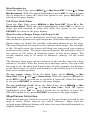
Sonar Menu with Ping Speed command selected (left).
The Ping Speed Control Bar (right) at default setting.
To change Ping Speed:
1. From the Sonar Page, press MENU|↓ to PING SPEED|ENT.
2. The Ping Speed Control Bar appears. Press ↑ to increase ping speed;
press ↓ to decrease ping speed. When it's set at the desired level, press EXIT.
To turn off HyperScroll:
1. From the Sonar Page, press MENU|↓ to PING SPEED|ENT.
2. The Ping Speed Control Bar appears. Press ↓ to decrease ping speed
to 50 percent. When it's set at the desired level, press EXIT.
When you boost ping speed and switch into HyperScroll, the width of
the FasTrack bar graph display doubles in width at the right side of the
screen. This allows you to better see the virtually instantaneous sonar
returns, just as you would on a flasher sonar unit. For more
information on FasTrack, see its entry in this section.
Reset Options
This command is used to reset all features, options and settings to their
original factory defaults. This is useful when you have changed several
settings and want to return the unit to basic automatic operation.
1. Press MENU|MENU|↓ to SYSTEM SETUP|ENT|↓ to RESET OPTIONS|ENT.
2. Press ← to YES|ENT.
3. All the menus are cleared and the unit reverts to the Map Page at
the 4000-mile zoom range, just as if you had turned it on for the first
time. All options have been returned to the factory settings.
79
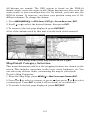
System Setup menu with Reset Options command selected (left). The
Reset Options dialog box (right).
NOTE:
Reset Options does not erase any waypoints, routes, plot trails, or
sonar logs.
Reset Water Distance
The sonar chart's Digital Data display option includes a window that
shows distance traveled, called Water Distance ("W Distance"). This
information is calculated from an optional water speed sensor, not the
GPS. The Water Distance window can be reset to zero using the Reset
Water Distance command.
Press
MENU|MENU|↓ to SONAR SETUP|ENT|↓ to RESET WATER
DISTANCE|ENT. The menus are cleared and the water distance is reset to
0.00.
Set Keel Offset
This unit measures water depth from the face of the transducer. Since
the transducer is installed below the water surface, the depth displayed
by the digital depth, chart depth scale, chart cursor or fish symbols is
not exact. If the transducer is 1 foot below the surface, and the screen
shows the water depth as 30 feet, then the actual depth is 31 feet.
On sailboats or other large vessels with deep drafts, the distance
between the transducer installation and the keel or lower engine unit
can be several feet. In those cases, an inexact depth reading could
result in grounding or striking underwater structure. The Keel Offset
feature eliminates the need for the navigator to mentally calculate how
much water is under his keel.
Keel Offset lets you calibrate the digital depth: chart depth scale, chart
cursor depth and fish symbol depth displayed on the screen. To calibrate
the depth indicators, first measure the distance from the face of the
80
transducer to the lowest part of the boat. In this example, we will use 3.5
feet. This will entered as a negative 3.5 feet, which makes the depth
indicators perform as if the transducer's lower in the water than it really
is.
1. Press MENU|MENU|↓ to SONAR SETUP|ENT.
2. Use ↓ to scroll down to KEEL OFFSET, then press ENT. The Keel Offset
dialog box appears. Press ↓ to change the plus (+) sign to a minus (–)
sign.
3. Press → to the first number, then press ↑ to change the number to 3.
4. Press → to the second number, then press ↑ to change the number to
5, then press EXIT. The depth indicators now accurately show the water
depth beneath the keel.
NOTE:
If knowing the exact depth of water beneath the keel is less
important, you can calibrate the depth indicators so that they show
the actual water depth from surface to bottom. To do this, first
measure the distance from the face of the transducer to the surface
(the water line on the boat). In this example, we will use 1.5 feet. This
will be entered as a positive 1.5 feet, which makes the depth
indicators perform as if the transducer's higher in the water than it
really is.
1. Press MENU|MENU|↓ to SONAR SETUP|ENT|ENT.
2. The Keel Offset dialog box appears with a plus (+) sign at the
front of the box.
3. Press → to the first number, then press ↑ to change the number
to 1.
4. Press → to the second number, press ↑ to change the number to
5, then press EXIT. The depth indicator now accurately shows the
water depth from surface to bottom.
Sensitivity & Auto Sensitivity
The sensitivity controls the ability of the unit to pick up echoes. A low
sensitivity level (from zero to 50 percent) excludes much of the bottom
information, fish signals, and other target information.
High sensitivity levels let you see this detail, but it can also clutter the
screen with many undesired signals. Typically, the best sensitivity level
shows a good solid bottom signal with some surface clutter.
81
Automatic Sensitivity
The default sensitivity mode is automatic. The unit bases the
sensitivity level on water depth and conditions. When the unit is in the
automatic mode, sensitivity is automatically adjusted to keep a solid
bottom signal displayed, plus a little more power. This gives it the
capability to show fish and other detail.
However, situations occur when it becomes necessary to increase or
decrease the sensitivity. This typically happens when you wish to see
more detail, so an increase in sensitivity is indicated. Or, wave action
and boat wakes create enough tiny air bubbles to clutter much of the
water column. In that case, a decrease in sensitivity is indicated to
reduce some of the clutter.
The control bar used to adjust sensitivity up or down is the same
whether the unit is in the automatic or manual mode. In automatic you
can adjust sensitivity up to 100 percent but the unit will limit your
minimum setting. In auto, the unit will continue to make small
adjustments, allowing for the setting you selected.
In manual mode, you have complete control over sensitivity, with the
ability to set it anywhere from zero to 100 percent. Once you select a
level in manual, the unit will continue to use that exact sensitivity
setting until you change it or revert to auto mode.
To adjust sensitivity in auto mode:
1. Press MENU|ENT.
2. The Sensitivity Control Bar appears. Press ↓ to decrease sensitivity;
press ↑ to increase sensitivity. When it's set at the desired level, press
EXIT. (When you reach the maximum or minimum limit, a tone sounds.)
Sonar Menu with Sensitivity command selected (left).
The Sensitivity Control Bar (right).
82
To adjust sensitivity in manual mode:
1. First, turn off Auto Sensitivity: from the Sonar Page, press MENU|↓
to AUTO SENSITIVITY|ENT.
2. Press ↑ to SENSITIVITY|ENT and the Sensitivity Control Bar appears.
Press ↓ or ↑ to pick a different sensitivity setting. When it's set at the
desired level, press EXIT.
To turn Auto Sensitivity back on:
From the Sonar Page, press MENU|↓ to AUTO SENSITIVITY|ENT|EXIT.
NOTE:
To return to the original factory setting for Auto Sensitivity, see the
entry in this section on Reset Options. If sensitivity is in manual
mode, the Reset Options command will switch back to Auto and
reset the factory setting at the same time.
Tip:
For quicker sensitivity adjustments, try leaving the Sensitivity
Control Bar on the screen as the chart scrolls. You can see the
changes on the screen as you press the up or down arrows. This is
handy when there's a lot of clutter in the water, and you are
matching the sensitivity to rapidly changing water conditions.
Sonar Chart Mode
The default color scheme for the sonar chart is grayscale, but we offer
other variations to suit your viewing preferences. The chart can be
displayed in Grayscale, Reverse Grayscale, Bottom Black or
FishReveal.
To change the chart mode:
1. From the Sonar Page, press MENU|↓ to SONAR FEATURES|ENT.
2.. Press → ↓ to SONAR CHART MODE|ENT.
3. Press ↓ or ↑ to Mode Name|ENT.
4. Press EXIT|EXIT to return to the Sonar Page.
Sonar Page & Sonar Chart Display Options
The Pages Menu offers five chart display options for units with dualfrequency transducers and four options for units with single-frequency
transducers. To access them, press PAGES|← or→ to SONAR|↓ to Option
Name|EXIT.
83
Pages Menu, showing sonar chart display options.
Full Sonar Chart
This is the default mode used when the unit is turned on for the first
time or when it's reset to the factory defaults.
The bottom signal scrolls across the screen from right to left. Depth
scales on the right side of the screen aid in determining the depth of
targets. The line at the top of the screen represents the surface. The
bottom depth and surface temperature (if equipped with a temperature
sensor or a transducer with a temp sensor built in) show at the top left
corner of the screen.
The FasTrack™ display shows just to the right of the scale. This
changes all echoes into short horizontal bars, replicating a flasher
sonar. The zoom bar on the far right shows the area magnified when
the zoom is in use. (See the Zoom section on page 92 for more
information.)
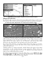
Full Sonar Chart. The Overlay Data (depth and water temperature)
are each set to a different text size.
84
Split Zoom Sonar Chart
A split chart shows the underwater world from the surface to the
bottom on the right side of the screen. The left side shows an enlarged
version of the right side. The zoom range shows at the bottom left
corner of the screen.
Split Zoom Sonar Chart. Image (left) shows the left window zoomed
to 2X. The image on the right shows the left window zoomed to 4X.
Split Frequency Sonar Chart
(Dual-Frequency Transducers only)
This page option shows sonar data from the 50 kHz transducer element
on the left side of the screen and data from the 200 kHz transducer on
the right side. All other functions and features are the same as the Full
Chart page.
Split Frequency Sonar Chart page, with
50 kHz view on the left and 200 kHz view on the right.
You can adjust the sensitivity in each window.
To adjust sensitivity in auto mode:
1. Press MENU|ENT.
2. The unit asks which you wish to adjust. Press ← or→ to select the
one you want then press ENT.
85
3. The Sensitivity Control Bar appears. Press ↓ to decrease sensitivity;
press ↑ to increase sensitivity. When it's set at the desired level, press
EXIT. (When you reach the maximum or minimum limit, a tone sounds.)
The Split Frequency Sonar Chart page allows you to adjust
sensitivity separately for each window.
Digital Data/Chart
This mode shows the chart on the right side of the screen. The left side has
four digital boxes containing, Depth, Track, Bearing and a Temperature
Graph.
Digital Data/Chart
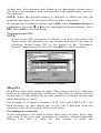
Customize Page Displays
Every Page display option except Full Map (on the Map Page) has
customizable Digital Data boxes to provide on-screen information.
The various data available from your unit are divided into categories in
the Data Viewer menu. These categories include GPS Data, Navigation,
86
Trip Calculator, Time, Sonar and Miscellaneous Data. You can select
items from any of these categories for display in any data box. The
category divisions are only there to help you sort through the
information.
To change information displayed in a data box:
On the page with the digital data box you wish to change, press
MENU|↓ to CUSTOMIZE|ENT. A data box name flashes, indicating it is
selected. Press ENT to modify the box or hit ↑ or ↓ to select another box,
then press ENT. You'll see a list of categories with "+" or "–" symbols
next to each category. A category with a "+" is expandable, meaning its
contents are hidden.
Data Viewer with the Sonar Data category expanded.
Selecting the category name and pressing ENT will show the category's
contents, so you can choose items within it. An expanded category (one
with a "–" next to its name) can be collapsed to hide its contents. Just
select the category name and press ENT.
Expand any categories that might contain data you want to display.
Then press ↓ or ↑ to select a different data option. With the new option
highlighted, press ENT to switch the contents of the box to the new data
type, then press EXIT. You can now select another box to change. When
you are finished with the settings, press EXIT again and the box name
stops flashing.
NOTE
A Page display can only show a limited number of data boxes.
FlashGraf
The FlashGraf sonar page option represents a flasher style sonar
combined with a scrolling chart. A circular dial shows all returning
echoes at a high screen refresh rate. It uses the Grayline feature to
87
show weaker targets as lighter shades. The bottom depth is shown as a
black bar across the outer circle. You can adjust the size of the chart
and the flasher windows by using the Resize Window command, which
is described on page 109.
Surface
clutter
Bottom signal
FlashGraf page.
Fish signal,
approximately
27 feet
Map With Sonar Split Screen
There is a page mode that splits the screen in half, with the map on the
left and the sonar on the right. This screen option can be found on the
Pages Menu under the Map Page category.
Map with Sonar split screen.
When this screen is activated, you need to specify which side of the Menu,
is active. To toggle between the two windows, press PAGES|PAGES. The
window with the black title bar at the top of the screen is the active
window. To switch back, just press PAGES|PAGES again.
88
Sonar Simulator
This unit has a built-in simulator that lets you run it as if you were on
the water. All sonar features and functions are useable. When in
simulator mode, you will see the chart file name in the Sonar Page title
bar and a play symbol will flash on and off at the right end of the title
bar. To use the simulator:
1. From the Sonar Page, press MENU|MENU|↓ to SONAR SETUP|ENT|↓ to
SONAR SIMULATOR ENT|ENT.
Main Menu with Sonar Setup command selected (left). Sonar
Simulator menu, with simulator turned on (right).
NOTE:
With Simulate Position checked, the simulator will also
automatically run the GPS simulator (if GPS data was recorded
with the sonar log).
2. To use the default sonar chart log stored in the unit, press ENT|EXIT.
The recorded chart begins scrolling across the screen, just as if you
were on the water.
3. Turn off Sonar Simulator by pressing MENU|MENU|↓ to SONAR
SETUP|ENT|↓ to SONAR SIMULATOR|ENT|ENT|EXIT.
"Play"
symbol
flashing
Title bar
with chart
file name
Sonar Page, playing a recorded sonar chart in Sonar Simulator mode.
89
Tip:
The Sonar Simulator can use sonar charts recorded (logged) on a
MMC card. (To see how, read the entry in this section on Log Sonar
Chart Data.) To play back a sonar chart, make sure the MMC
containing the chart is installed, then:
1. Press MENU|MENU|↓ to SONAR SETUP|ENT|↓ to SONAR SIMULATOR|ENT.
2. Press ↓ to CHART USED|ENT.
3. Press ↓ or ↑ to select chart name|ENT|↑ to SONAR SIMULATOR
ON|ENT|EXIT.
While you're in the Sonar Simulator menu, don't forget to check
Simulate Position if you want to run the sonar and GPS simulators
simultaneously. As you review sonar logs, you can create waypoints
to mark sites you want to return to.
While the simulator is running, you can switch from one chart log
to another by opening the Sonar Simulator menu and using the
instructions in step 2 to select a different chart.
NOTE:
If you turn on your unit before attaching a transducer, it may enter
a demo mode. The words "demo mode" flash on the bottom of the
screen and a sonar chart plays much like the simulator. Unlike the
simulator, the demo mode is for demonstration only, and will
automatically stop as soon as you turn on the unit with a
transducer attached. The simulator will continue to function
normally.
Stop Chart
If you are running multiple units on a boat or using this unit in a car,
there are times when you may want to turn off the sonar. This
command turns off the sonar and stops the chart from scrolling. Sonar
restarts automatically each time you turn on your unit.
Press MENU|↓ to STOP CHART|ENT|EXIT.
To turn on sonar and start the chart scrolling again, repeat the above step.
90
Sonar Menu with Stop Chart command selected.
Surface Clarity
The markings extending downward from the zero line on the chart are
called "surface clutter." These markings are caused by wave action,
boat wakes, temperature inversion and more.
The surface clarity control reduces or eliminates surface clutter signals
from the display. It does this by changing the sensitivity of the receiver,
decreasing it near the surface and gradually increasing it as the depth
increases.
There are three levels of surface clarity available: low, medium, or high.
It can also be turned off. The default level is off.
To adjust the Surface Clarity level:
1. From the Sonar Page, press MENU|↓ to SONAR FEATURES|ENT.
Sonar Features menu with Surface Clarity selected.
2. Press → to SURFACE CLARITY|ENT.
3. Press ↓ or ↑ to select clarity level|EXIT|EXIT|EXIT.
91
Surface clutter
In the illustration on the left, Surface Clarity is turned off.
The view on the right shows Surface Clarity set on high.
Upper and Lower Limits
See the entry in this section for Depth Range - Upper and Lower Limits
Zoom & Zoom Bar
"Zooming in" is a common, fast and easy method used to enlarge small
detail, fish signals and the bottom with its associated structure. This
unit lets you zoom in quickly and easily by pressing the Zoom In key,
ZIN.
Pressing ZIN once doubles the size (2X) of all echoes on the screen.
Pressing it again quadruples the size of the echoes (4X). The zoom bar
on the far right side of the screen shows which echoes will be displayed
on the screen when the ZIN key is pressed.
For example, pressing the ZIN key once will enable a 2X zoom that will
show all echoes that are between the top and bottom of the 2X-zoom
bar. Pressing the key again will give a 4X zoom and only the echoes
between the top and bottom of the 4X bar will show on the screen.
Press the Zoom Out key, ZOUT, to return the display to the normal mode.
Sonar page zoomed 2X (left). The same view zoomed 4X (right).
92
Zoom Pan
Your unit has the handy ability to quickly zoom in on any portion of the
water column with just the touch of an arrow key. The Zoom Pan feature
lets you rapidly move the zoomed area up and down to different depths.
By "pointing" your zoom at different portions of the chart as it scrolls,
you can get a good, close-up look at structure or cover below you.
To use Zoom Pan, switch to a manual Depth Range setting (see page
67) and turn on 2X or 4X Zoom. Then press ↑ or ↓ to pan up and down
the water column.
93
Notes
94
Section 5:
Sonar Troubleshooting
If your unit is not working, or if you need technical help, please use the
following troubleshooting section before contacting the factory customer
service department. It may save you the trouble of returning your unit
for repair. For contact information, refer to the last page, just inside the
back cover of this manual.
Unit won't turn on:
1. Check the power cable's connection at the unit. Also check the wiring.
2. Make certain the power cable is wired properly. The red wire
connects to the positive battery terminal, black to negative or ground.
3. Check the fuse.
4. Measure the battery voltage at the unit's power connector. It should
be at least 11 volts. If it isn't, the wiring to the unit is defective, the
battery terminals or wiring on the terminals are corroded, or the
battery needs charging.
Unit operates only in demo mode:
The transducer or antenna module have not yet been connected or have
been disconnected. To leave demo mode, make sure that either the
transducer or the antenna is securely connected before turning the unit on.
Unit freezes, locks up, or operates erratically:
1. Electrical noise from the boat's motor, trolling motor, or an accessory
may be interfering with the sonar unit. Rerouting the power and
transducer cables away from other electrical wiring on the boat may
help. Route the sonar unit's power cable directly to the battery instead
of through a fuse block or ignition switch
2. Inspect the transducer cable for breaks, cuts, or pinched wires.
3. Check both the transducer and power connectors. Make certain both
are securely plugged in to the unit.
Weak bottom echo, digital readings erratic, or no fish signals:
1. Make certain the transducer is pointing straight down. Clean the
face of the transducer. Oil, dirt and fuel can cause a film to form on the
transducer, reducing its effectiveness. If the transducer is mounted
inside the hull, be sure it is shooting through only one layer of
fiberglass and that it is securely bonded to the hull. Do NOT use RTV
silicone rubber adhesive or Marine-Tex epoxy.
2. Electrical noise from the boat's motor can interfere with the sonar.
95
This causes the sonar to automatically increase its Discrimination or
noise rejection feature. This can cause the unit to eliminate weaker
signals such as fish or even structure from the display.
3. The water may be deeper than the sonar's ability to find the bottom.
If the sonar can't find the bottom signal while it's in the automatic
mode, the digital sonar display will flash continuously. It may change
the range to limits far greater than the water you are in. If this
happens, place the unit in the manual mode, then change the range to a
realistic one, (for example, 0-100 feet) and increase the sensitivity. As
you move into shallower water, a bottom signal should appear.
4. Check the battery voltage. If the voltage drops, the unit's transmitter
power also drops, reducing its ability to find the bottom or targets.
Bottom echo disappears at high speeds or erratic digital
reading or weak bottom echo while boat is moving
1. The transducer may be in turbulent water. It must be mounted in a
smooth flow of water in order for the sonar to work at all boat speeds. Air
bubbles in the water disrupt the sonar signals, interfering with its ability
to find the bottom or other targets. The technical term for this is
cavitation.
2. Electrical noise from the boat's motor can interfere with the sonar.
This causes the sonar to automatically increase its Discrimination or
noise rejection feature. This can cause the unit to eliminate weaker
signals such as fish or even structure from the display. Try using
resistor spark plugs or routing the sonar unit's power and transducer
cables away from other electrical wiring on the boat.
No fish arches when the Fish I.D. feature is off:
1. Make certain the transducer is pointing straight down. This is the
most common problem if a partial arch is displayed.
2. The sensitivity may not be high enough. In order for the unit to
display a fish arch, it has to be able to receive the fish's echo from the
time it enters the cone until it leaves. If the sensitivity is not high
enough, the unit shows the fish only when it is in the center of the cone.
3. Use the Zoom feature. It is much easier to display fish arches when
zoomed in on a small range of water than a large one. For example, you
will have much better luck seeing fish arches with a 30 to 60 foot range
than a 0 to 60 foot range. This enlarges the targets, allowing the
display to show much more detail.
4. The boat must be moving at a slow trolling speed to see fish arches.
If the boat is motionless, fish stay in the cone, showing on the screen as
straight horizontal lines.
96
NOISE
A major cause of sonar problems is electrical noise. This usually
appears on the sonar's display as random patterns of dots or lines. In
severe cases, it can completely cover the screen with black dots, or
cause the unit to operate erratically, or not at all.
To eliminate or minimize the effects of electrical noise, first try to
determine the cause. With the boat at rest in the water, the first thing
you should do is turn all electrical equipment on the boat off. Make sure
the engine is also off. Turn your sonar on, then turn off Noise Reject
[also known as the ASP feature (Advanced Signal Processing)].
Sensitivity should be set at 90-95 percent. There should be a steady
bottom signal on the display. Now turn on each piece of electrical
equipment on the boat and view the effect on the sonar's display. For
example, turn on the bilge pump and view the sonar display for noise. If
no noise is present, turn the pump off, then turn on the VHF radio and
transmit. Keep doing this until all electrical equipment has been
turned on, their effect on the sonar display noted, then turned off.
If you find noise interference from an electrical instrument, trolling
motor, pump, or radio, try to isolate the problem. You can usually
reroute the sonar unit's power cable and transducer cable away from
the wiring that is causing the interference. VHF radio antenna cables
radiate noise when transmitting, so be certain to keep the sonar's wires
away from it. You may need to route the sonar unit's power cable
directly to the battery to isolate it from other wiring on the boat.
If no noise displays on the sonar unit from electrical equipment, then
make certain everything except the sonar unit is turned off, then start
the engine. Increase the RPM with the gearshift in neutral. If noise
appears on the display, the problem could be one of three things; spark
plugs, alternator, or tachometer wiring. Try using resistor spark plugs,
alternator filters, or routing the sonar unit's power cable away from
engine wiring. Again, routing the power cable directly to the battery
helps eliminate noise problems. Make certain to use the in-line fuse
supplied with the unit when wiring the power cable to the battery.
When no noise appears on the sonar unit after all of the above tests,
then the noise source is probably cavitation. Many novices or persons
with limited experience make hasty sonar installations which function
perfectly in shallow water, or when the boat is at rest. In nearly all
cases, the cause of the malfunction will be the location and/or angle of
the transducer. The face of the transducer must be placed in a location
that has a smooth flow of water at all boat speeds. Read your
transducer owner's manual for the best mounting position.
97
Notes
98
Section 6:
Basic GPS Operations
This section addresses the unit's most basic GPS operations. The
tutorials presented in Sec. 6 follow a chronological order. Sec. 7,
Advanced GPS Operations, will discuss other more advanced functions
and utilities. Material in Sec. 7 is arranged in alphabetical order.
Before you turn on the unit and find where you are, it's a good idea to
learn about the different keys, the four Page screens and how they all
work together. BUT, if you just can't wait to get outside, turn to the
one-page Quick Reference on page 111.
Keyboard
4
8
9
2
7
3
6
5
1
MMC drawer
LCX-17M sonar/GPS unit, front view, showing sonar screen, keyboard
and access door for the MMC compartment.
1. PWR/LIGHT (Power & Light) – The PWR key turns the unit on and
off and activates the backlight.
2. PAGES – Pressing this and the ← → arrow keys (4) switches the
unit between the four different page screens. (Satellite Status Page,
99
Navigation Page, Map Page and Sonar Page.) Each page represents one
of the unit's major operation modes.
3. MENU – Press this key to show the menus and submenus, which
allow you to select a command or adjust a feature. This also accesses
search functions for streets, intersections, addresses and highway exits.
4. ARROW KEYS – These keys are used to navigate through the
menus, make menu selections, move the map cursor and sonar chart
cursor and enter data.
5. ENT/ICONS (Enter & Icons) – This key allows you to save data,
accept values or execute menu commands. It is also used to create
event marker icons.
6. EXIT – The Exit key lets you return to the previous screen, clear
data or close a menu.
7. WPT – (Waypoint) The Waypoint key is used to save and recall
waypoints, search for waypoints and access the waypoint list. It also
launches the Point-of-Interest (POI) search menus and is involved in
some navigation functions.
8. ZOUT – (Zoom Out) – This key lets you zoom the screen out. On the
Sonar Page, this key returns you to a full sonar chart display, showing
the entire water column from surface to bottom. On the Map Page, this
lets you see a larger geographic area on the map. Less detail is seen as
you zoom out.
9. ZIN – (Zoom In) – This key lets you zoom the screen in. On the Sonar
Page, this key enlarges fish signals and bottom detail. On the Map
Page, zooming in lets you see greater detail in a smaller geographic
area on the map.
Power/lights on and off
To turn on the unit, press PWR. As the unit powers up, the Map Page is
displayed first. (To switch to another page, press PAGES|← or → to
Page Name|EXIT.)
To turn on the backlight, press PWR again. The unit has three backlight
levels to select from. Repeatedly pressing PWR will cycle through the
backlight settings and turn off the backlight.
Turn off the unit by pressing and holding the PWR key for 3 seconds.
Main Menu
The unit has a Main Menu, which contains some function commands
and some setup option commands. The tutorial lessons in this section
100
will deal only with functions and basic commands that make the Unit
do something. The unit will work fine for these lessons right out of the
box with the factory default settings. But, if you want to learn about
the various options, see Sec. 8, System Setup and GPS Setup Options.
You can access the Main Menu from any of the four Page screens by
pressing MENU|MENU. To clear the menu screen and return to the page
display, press EXIT.
Main Menu.
The Main Menu commands and their functions are:
Screen command: changes the contrast or brightness of the display
screen.
Sounds command: enables or disables the sounds for key strokes and
alarms and sets the alarm style.
Alarms command: turns GPS or sonar alarms on or off and changes
alarm thresholds.
Route Planning command: used to plan, view or navigate a route.
My Trails command: shows, hides, creates and deletes plot trails. Also
used to navigate or backtrack a trail.
Cancel Navigation command: turns off the various navigation
commands. Used to stop navigating after you have reached your
destination waypoint, Point of Interest or map cursor location; or after
you reach the end of a route or trail.
Sonar Setup command: sets various sonar options.
GPS Setup command: sets various GPS receiver options.
System Setup command: sets general configuration options.
Sun/Moon Calculations command: finds the rising and setting time
of the sun and the moon.
101
Trip Calculator command: shows trip status and statistics.
Timers command: controls the up timer, down timer and alarm clock
settings.
Browse MMC Files command: this allows you to view the installed
MMC card and the files it contains.
Pages
The unit has four Page displays that represent the four major operating
modes. They are the Satellite Status Page, the Navigation Page, Map
Page and the Sonar Page. They are accessed by pressing the PAGES key,
then using → or ← to select a Page. (Clear the menu by pressing EXIT.)
Pages Menu, showing some Map display options.
Sonar Page
The Sonar Page displays the sonar chart, a view of the water column
from the surface to the bottom. The chart scrolls across the screen from
right to left, displaying signal echoes that represent fish, structure and
the bottom. The Sonar Page is discussed in detail in Sec. 3. To get to
the Sonar Page: Press the PAGES key, then use → or ← to select SONAR.
(Clear the Pages Menu by pressing EXIT.)
Satellite Status Page
The Satellite Status Page, shown, provides detailed information on the
status of the unit's satellite lock-on and position acquisition. To get to
the Satellite Status Page: Press the PAGES key, then use → or ← to
select STATUS. (Clear the Pages Menu by pressing EXIT.)
No matter what Page you are on, a flashing current position
indicator/question mark symbol and flashing GPS data displays
indicate that satellite lock has been lost and there is no position
confirmed. The Satellite Status Page shows you the quality and
accuracy of the current satellite lock-on and position calculation.
102
WARNING:
Do not begin navigating with this unit until the numbers
have stopped flashing!
Satellite Status Page. Left view indicates unit has not locked on
to any satellites and does not have a fix on its position. Right
view shows satellite lock-on with a 3D position acquired
(latitude, longitude and altitude), and WAAS reception.
This screen shows a graphical illustration of the satellites that are in view.
Each satellite is shown on the circular chart relative to your position. The
point in the center of the chart is directly overhead. The small inner ring
represents 45° above the horizon and the large ring represents the horizon.
North is at the top of the screen. You can use this to see which satellites are
obstructed by obstacles in your immediate area if the unit is facing north.
The GPS receiver is tracking satellites represented by a black bar. The
receiver hasn't locked onto a satellite if the number is a lighter shade,
therefore it isn't being used to solve the position.
Beneath the circular graph are the bar graphs, one for each satellite in
view. Since the unit has twelve channels, it can dedicate one channel
per visible satellite. The taller the bar on the graph, the better the unit
is receiving the signals from the satellite.
The "Estimated Position Error" (horizontal position error) shown in the
upper left corner of the screen is the expected error from a benchmark
location. In other words, if the EPE shows 50 feet, then the position
shown by the unit is estimated to be within 50 feet of the actual
location. This also gives you an indicator of the fix quality the unit
currently has. The smaller the position error number, the better (and
more accurate) the fix is. If the position error flashes dashes, then the
unit hasn't locked onto the satellites, and the number shown isn't valid.
103
The Satellite Status Page has its own menu, which is used for setting
various options. (Options and setup are discussed in Sec. 8.) To access
the Satellite Status Page menu, from the Status Page, press MENU
Navigation Page
This screen has a compass rose that not only shows your direction of
travel, but also the direction to a recalled waypoint. It also has a
Navigation with Sonar option that will display two windows, one with a
sonar chart, the other with the compass rose. To get to the Navigation
Page: Press PAGES| → or ← to NAVIGATION|EXIT.
The navigation screen looks like the one below when you're not
navigating to a waypoint or following a route or trail. Your position is
shown by an arrow in the center of the screen. Your trail history, or
path you've just taken, is depicted by the line extending from the arrow.
The arrow pointing down at the top of the compass rose indicates the
current track (direction of travel) you are taking.
Track or compass heading indicator, showing direction of travel
Navigation
information
Compass
displays
rose
Present
position
arrow
Trail line
Navigation Page, recording a trail, traveling east. Page looks like
this when the unit is not navigating to a waypoint , following
a route, or backtracking a trail.
NOTE:
Remember, when information displays are flashing, satellite lock
has not been achieved and no position fix has been determined. A
question mark will also flash on the present position arrow in the
center of the compass rose.
104
When navigating to a waypoint, the Navigation screen looks like the
following figure. Your ground speed, track, distance and bearing to
waypoint, and course are all shown digitally on this screen.
Current track or
heading, shown
in degrees
Course line (dotted)
Bearing
arrow
Compass
bearing to
destination
Waypoint
symbol
Navigation
information
displays
Cross track
error range
(off course
indicator)
Left cross
track error
Trail line
(solid)
Destination
name
Navigation Page, backtracking a trail while creating a new trail.
In the example figure above, the driver is headed north (a 355º track)
toward a waypoint 358º (bearing) away. The cross track error range
(white corridor) is 0.20 miles either side of the course. The driver is
headed toward trail waypoint 1, which is 0.18 miles away. The vehicle
is virtually on course (off course only 49 feet to the left). Traveling at a
speed of 46 mph, the driver will arrive at the waypoint in 14 seconds.
Speed (ground speed) is the velocity you are making over the ground. (If
you wish, you can customize the Speed window to display Closing
Speed instead. Closing Speed is also known as velocity made good. It's
the speed that you're making toward the waypoint. For instructions,
see the Customize Page Displays entry in Sec. 8.)
Track is the heading, or the current direction you are actually
traveling. Bearing is the direction of a line-of-sight from your present
position to the destination. No matter what direction you are steering,
the Bearing window shows the compass direction straight to the
destination from your location at the moment. Distance shows how far
it is to the waypoint you're navigating toward.
The Off Course window shows the current cross track error. This shows
the distance you are off-course to the side of the desired course line. The
course line is an imaginary line drawn from your position when you
started navigating to the destination waypoint. The course line is shown
105
on the Navigation Page screen (and the Map Page screen) as a line.
The cross track error range is shown on the compass rose as a wide,
white, corridor enclosing the course line. The outer edges of this white
corridor represent lines that show the current cross track error range.
The default for the cross track error range is 0.20 miles.
For example, if the present position symbol touches the right cross
track error line, then you are 0.20 miles to the right of the desired
course. You need to steer left to return to the desired course. You can
use the ZIN or ZOUT keys to change the cross track error range.
A circular symbol depicting your destination (waypoint) appears on the
screen as you approach the waypoint.
Trip Time is the time that it will take to reach your destination at your
present closing speed. (You can also customize the time window to show
Arrival Time instead. Arrival Time is the local time it will be when you
arrive at the destination, based upon your present closing speed and
track.)
The Navigation Page has its own menu, which is used for some
advanced functions and for setting various options. (Options and setup
are discussed in Sec. 8.) To access the Navigation Page Menu, from the
Navigation Page, press MENU.
Map Page
The Map Page screens show your course and track from a "bird's-eye"
view. By default, this unit shows the map with north always at the top
of the screen. (This can be changed. See the topic Map Orientation, in
Sec. 8.) If you're navigating to a waypoint, the map also shows your
starting location, present position, course line and destination. You,
however, don't have to navigate to a waypoint to use the map.
Map Page is the default screen that appears when you turn on the unit.
To get to the Map Page from another page: Press PAGES| → or ← to
MAP|EXIT. When the Map Page is displayed, a screen similar to the
following figure appears.
The arrow in the center of the screen is your present position. It points
in the direction you're traveling. The map zoom range is the distance
across the screen. This number shows in the lower right corner. In the
following example, the first figure shows a range of 4,000 miles and the
last figure range is 15 miles (from the left edge of the map to the right
edge of the map).
The Zoom In and Zoom Out keys zoom the map to enlarge or reduce its
coverage area and the amount of mapping detail shown. There are 37
available map zoom ranges, from 0.05 miles to 4,000 miles.
106
Far left, Map Page opening screen. Center, zoomed to 100 miles and
right, zoomed to 15 miles. The Over Zoomed notice in the top left
corner means you have reached the map’s detail limits for the area.
Zooming in any closer will reveal no more map details because a
custom map has not been loaded on the MMC.
If you're using only the factory-loaded background map, the maximum
zoom range is 20 miles. You can continue to zoom in closer, but the map
will simply be enlarged without revealing more map content (except for
a few major city streets.) Load your own high-detail custom map made
with MapCreate and you can zoom in to 0.05 miles.
Map Pages with high-detail MapCreate map. Arterial streets appear at
the 6-mile zoom range, with a few Point of Interest icons visible (left).
Numerous Points of Interest dots become visible at the 3-mile range,
along with minor streets (center). At the 0.6-mile zoom, you can see an
interstate highway with an exit, major and minor streets as well as
Point of Interest icons (right).
Background map vs. MapCreate map content
The background map includes: low-detail maps of the whole world,
containing cities, major lakes, major rivers, political boundaries, and
medium-detail maps of the United States.
The medium-detail U.S. maps contain: all incorporated cities; shaded
metropolitan areas; county boundaries; shaded public lands (such as
national forests and parks); some major city streets; Interstate, U.S.
and state highways; Interstate highway exits and exit services
information; large- and medium-sized lakes and streams; and more
than 60,000 navigation aids with 10,000 wrecks and obstructions in
U.S. coastal and Great Lakes waters
107
MapCreate custom maps include massive amounts of information not
found in the background map. MapCreate contains: Points of Interest
database, all the minor roads and streets, all the landmark features
(such as summits, schools, radio towers, etc.); more rivers, streams,
smaller lakes and ponds and their names.
What's more important is the large scale map detail that allows your
GPS unit to show a higher level of position accuracy. For example, the
background map would show you the general outline and approximate
shape of a coastline or water body, but the higher detail in MapCreate
shows the shoreline completely and accurately. Many smaller islands
would not be included in the background map, but are in MapCreate.
Interstate
Major Street
Cursor line
Minor
Streets
POI Pop-up,
with position,
distance and
bearing data
POI
Marker
School POI
Zoom Range
Restaurant
POI
When the map is zoomed out far enough, most POIs appear as square
dots (left). As you zoom in closer, the symbols become readable icons.
In the 0.6-mile zoom example (right), the cursor has selected the Cupps
Café POI, which triggers a pop-up box with the POI name. This pop-up
box works on POIs at any zoom range.
Tip:
In some urban areas, businesses are so close to one another that
their POI icons crowd each other on the screen. In the preceding
figure, you can see a jumbled pile of POIs along Highway 34. You
can reduce screen clutter and make streets and other map features
easier to see by turning off the display of undesired POIs. (To see
how, check out the Map Detail Category section, page 152.)
The Map Page has its own menu, which is used for several functions
and for setting various options. To access the Map Page Menu, from the
Map Page, press MENU.
The Pages Menu also offers several map display options under the Map
108
Page category. To access
Option|EXIT.
THEM,
press PAGES|← or→ to MAP|↓ to
Digital Data map page (left); Two Position Formats page (right).
Pages Menu with Two Maps option selected (left).
Map Page with two map windows (right). The left map is active.
In pages that have two major windows (such as two maps) you can toggle
back and forth between the two windows by pressing PAGES|PAGES. This
allows you to change which map the cursor, keyboard and menus operate
on. A black title bar denotes the active window.
Resize Window is another handy feature for pages that have two major
windows. You can change the horizontal size of the windows to suit
your viewing preference. Here's how:
1. From any two-window display, press MENU|↓ to RESIZE WINDOW|ENT.
2. Two flashing arrows appear along the centerline dividing the two
windows. Press ← or → to adjust the window widths. Press EXIT to clear
the menu. When you are using the Two Maps page, four flashing
arrows appear, which allow you to not only resize the window from side
to side, but also gives you the option of stacking the windows, one on
top of the other.
109
The Two Maps page with one window stacked on top of the other.
3. To change the window size again or revert back to the original
display, just follow the steps above. (Most dual-window displays use
half the screen for each window by default.) You can also use the Reset
Options command to revert to the factory default.
Map Menu with Resize Window command selected (left). Pressing →
moves the centerline and enlarges the left window (right).
The following page contains a 12-step quick reference for the most basic
GPS operations. If you don't want to carry the manual with you as you
practice with the unit, you might consider photocopying this quick
reference page and tucking it into your pocket.
110
GPS Quick Reference
Start outdoors, with a clear view of the open sky. As you practice, try
navigating to a location at least a few blocks away. While you're learning,
navigation in too small an area will constantly trigger arrival alarms.
1. Connect the unit to electric power and the antenna module. Make sure
the MMC is in. (See complete installation details beginning on page 13.)
2. To turn on the unit, press and release PWR key.
3. Opening screen displays map of North America at the 4,000-mile
zoom range. Rotate through the four main Page screens (Map Page,
Satellite Status Page, Navigation Page and Sonar Page) by pressing
PAGES|← or → to select Page Name|EXIT. Switch Pages to display
Satellite Status Page.
4. Wait while unit locates satellites and calculates current position. Process
is visible on Satellite Page. This takes an average of 1 minute or less under
sky conditions unobstructed by terrain or structures. When the unit
acquires position, a tone sounds and a position acquired message appears.
5. With position acquired, press the PAGES key to display the Map
Page, which shows a bird's eye view of the earth. You can move around
the map by:
Zoom in closer to see greater detail: press ZIN (zoom in key.)
Zoom out to see more area, less detail: press ZOUT (zoom out key.)
Scroll map north, south, east or west using arrow keys ↑ ↓ → ← .
To stop scrolling and return to current position on map, press EXIT key.
6. Set a waypoint (Wpt 001) at your current position so you can
navigate back here: press WPT|WPT. Waypoint symbol and "001"
appears.
7. Zoom/scroll map to find a nearby object or location to go to. Use
arrow keys to center cursor cross-hair over the map object or location.
8. Navigate to the selected destination: press MENU|ENT. Follow the course
line on Map Page or compass bearing arrow on Navigation Page.
9. At destination, Arrival Alarm goes off; to clear it, press EXIT. Cancel
navigation: press MENU|MENU|↓ to CANCEL NAVIGATION|ENT|← to YES|ENT.
10. Return to Wpt 1 by Navigate To Waypoint or Backtrack Trail. To
Waypoint: press WPT|→ to SAVED|ENT|ENT|ENT. Use ↑ or ↓ to select
Wpt 001, press ENT|ENT; follow navigation displays. Trail: press
MENU|MENU|↓ to MY TRAILS|ENT. Press ↓ to Trail 1|ENT|→|↓ to
NAVIGATE|ENT|↓ to NAVIGATE|→ to REVERSE|ENT|← to NAVIGATE|ENT. (If
arrival alarm sounds, press EXIT.) Follow navigation displays.
11. Back home, Arrival Alarm goes off; press EXIT. Cancel navigation:
press MENU|MENU|↓ to CANCEL NAVIGATION|ENT|← to YES|ENT.
12. To turn off the unit, press and hold PWR key for three seconds.
111
Find Your Current Position
Finding your current position is as simple as turning the unit on.
Under an unobstructed sky, the unit automatically searches for
satellites and calculates its position in approximately one minute or
less.
If for some reason satellite acquisition takes longer, you may be inside
a structure or vehicle or in terrain that is blocking signal reception. To
correct this, be sure you are positioned so the unit's antenna module
has as clear a view of the sky as possible, then turn the unit off and
back on again.
Moving Around the Map: Zoom & Cursor Arrow Keys
The map is presented from a bird's eye view. The current zoom range
shows in the lower right corner of the screen.
1. Press the ZIN key (zoom in) to move in closer and see greater detail in a
smaller geographic area.
2. Press the ZOUT key (zoom out) to move farther away and see less map
detail, but a larger geographic area.
When you are traveling, the map will automatically move as you move.
This keeps your current location roughly centered on the screen.
You can manually pan or scroll the map northward, southward,
eastward or westward by using the arrow keys, which launch the crosshair map cursor. This allows you to look at map places other than your
current position. To clear the cursor, press EXIT, which switches the
map back to the current position or the last known position.
Tip:
Use the cursor to determine the distance from your current position
to any map object. Simply use the arrow keys to position the cursor
over the object or landmark. The distance, measured in a straight
line, appears in the pop-up box. Press EXIT to clear the cursor.
112
Cursor line
Selected
airport
POI pop-up
name box
Distance
measured
by cursor
Cursor line
The selected airport to the northwest is 4.25 miles away.
Selecting Any Map Item With the Cursor
1. Use the zoom keys and the arrow keys to move around the map and
find the item you wish to select.
2. Use the arrow keys and center the cursor cross-hair on the desired
object. On most items, a pop-up box will give the name of the selected
item.
Searching
Now that you've seen how the unit can find where you are, let's search
for something somewhere else. Searching is one of the most powerful
features in the Lowrance GPS product line.
In this example, we'll look for the nearest fast-food restaurant. For more
information on different types of searches, refer to Sec. 9, Searching.
NOTE:
This example requires the Point of Interest (POI) database included
with a high detail MapCreate 6 custom map.
After the unit has acquired a position:
1. Press WPT|↓ to POI-RESTAURANTS.
2. You could search the entire restaurant category, but in this example
we will narrow our search. Press → to SUBCATEGORY column|↓ to FAST
FOOD CHAINS|ENT| ↓ to NEAREST|ENT.
3. The unit says it is calculating, then a list of restaurants appears,
with the closest at the top of the list, and the farthest at the bottom of
the list. The nearest is highlighted.
113
Category Selection menu (left) and list of the nearest restaurants (right).
4. You could select the nearest restaurant at the top, but we have
chosen a restaurant further down the list. Press ENT.
5. The POI information screen appears. This is how you can use the
unit as a business phone directory! If you wanted to navigate there, you
could press ENT, since the GO TO WAYPOINT command is highlighted. But
we just want to see it on the map, so press ↓ to FIND ON MAP |ENT.
POI information screen on the nearest fast food restaurant, showing
name, street address, phone number, latitude/longitude distance and
compass bearing. The Go To command is selected (left). The figure on
the right has the Find On Map command highlighted.
6. The unit's map appears, with the cross-hair cursor highlighting the
restaurant's POI symbol. A pop-up name box identifies the POI, as well
as its distance and bearing. A data box at the bottom of the screen
continues to display the location's latitude and longitude.
114
Map screen showing the result of a restaurant search.
7. To clear the search and return to the last page displayed, press
EXIT|EXIT. (Before you completely exited out of the Search menus, you
could have gone looking for another place.)
NOTE:
Search works from mapping and POI data loaded in the unit. If you
have not loaded a MMC for the area you are searching, you may not
find anything.
Set a Waypoint
A waypoint is simply an electronic "address," based on the latitude and
longitude of a position on the earth. A waypoint represents a location,
spot or destination that can be stored in memory, then recalled and
used later for navigational purposes.
You can create a waypoint at the cursor position on the map or at your
current position, while you are navigating. You can create a waypoint
at any location by manually entering the position's latitude and
longitude. It is also possible to copy waypoints from your unit to your
personal computer with MapCreate software. When you want to repeat
a trip, these archived waypoints can be reloaded into your GPS unit.
To create and save a Waypoint
These first two techniques use the Quick Save method, the fastest and
easiest way to create a waypoint.
Create Waypoint at Current Position
While you are traveling, press WPT|WPT. The waypoint is saved and
automatically given a name with a sequential number, such as
"waypoint 003." The waypoint symbol and number appear on the map.
115
Fig 1.
Fig 2.
Fig 3.
Fig 4.
Sequence for setting a waypoint. Fig. 1: While traveling, press WPT
twice to call up the Find Waypoint screen (Fig. 2) and set a point. Fig.
3: A message says the waypoint has been saved. Fig. 4: vehicle
continues on its way; the waypoint number is visible on map.
NOTE:
The Quick Save method uses the default waypoint symbol until you
edit an existing waypoint and change its symbol. (Edit Waypoint
Symbol is described in Sec. 7.) After you have changed a waypoint
symbol, the unit will remember the one you chose and use it the
next time you "quick save" a waypoint. To revert back to the default
symbol, edit a waypoint and choose it, or use the Reset Options
command (described in Sec. 8).
Create Waypoint on Map
1. Use the arrow keys to move the cursor to the place where you want
to make a waypoint.
2. Press WPT|WPT. The waypoint is saved and automatically given a
name with a sequential number, such as "waypoint 001." The waypoint
symbol and number appear on the map.
116
Create Waypoint by Entering a Position
1. Press WPT|→ to SUBCATEGORY column|↓ to NEW|ENT.
2. Press ↓ to ENTERED POSITION|ENT|→ to CREATE|ENT.
3. Press → to LATITUDE|ENT. Enter the latitude by pressing ↑ or ↓ to
change the first character, then press → to the next character and
repeat until the latitude is correct. Press ENT.
4. Press ↓ to LONGITUDE|ENT. Enter the longitude by pressing ↑ or ↓ to
change the first character, then press → to the next character and repeat
until the longitude is correct. Press ENT, then EXIT|EXIT to return to the
previous page display. The waypoint is saved and automatically given a
name with a sequential number, such as "waypoint 001." The waypoint
symbol and number appear on the map and in the waypoint list.
Navigate To a Waypoint
You can select any waypoint visible on the Map Page with the cursor,
then use the Navigate to Cursor command, which will be covered later
in this section. You can avoid scrolling the map to pick your waypoint if
you use the Find Waypoint commands:
1. Press WPT|→ to SAVED|ENT. To look up the nearest waypoint, press
↓ to NEAREST|ENT; or, to look by name and scroll through the entire
waypoint list, just press ENT. For this example, we’ll look by name.
2. If your waypoint list is a long one, you can spell out the waypoint
name in the FIND BY NAME box. Press ↑ or ↓ to change the first character,
then press → to move the cursor to the next character and repeat until
the name is correct, then press ENT to jump to the list below.
3. If the list is short, you can jump directly to the FIND IN LIST box by
pressing ENT. Use ↑ or ↓ to select the waypoint name, press ENT and
the waypoint information screen appears with the GO TO command
selected.
4. To begin navigating to the waypoint, press ENT.
117
Off course
range, set
at 0.20 mile
Waypoint
Course
line
Destination
name
Trail line
Navigation Page, navigating toward waypoint 001.
Set Man Overboard (MOB) Waypoint
One of boating's most terrifying events is having a friend or family
member fall overboard. It's particularly dangerous at night or if you're
out of sight of land. Of course, the first thing to do is remain calm and
then use all standard safety procedures to rescue the person.
This unit has a man overboard feature that shows navigation data to
the location where the feature was activated. To activate it, press the
ZOUT and ZIN keys at the same time. Your position at the time these
keys are pressed is used as the man overboard position.
Caution:
Saving a new "Man Overboard" waypoint will erase the previous
"Man Overboard" waypoint.
Navigate Back to MOB Waypoint
Find your way back to the accident position with the Navigation Page
or Map Page. When MOB is activated, the Navigation Page
automatically shows the compass rose with its bearing arrow pointing
toward the man overboard position, and the destination name says
"Going To Man Overboard." The Map Page displays a Man Overboard
waypoint, represented by a human figure, and the steering arrow
points where to steer to reach that position.
118
Navigating to Man Overboard: Navigation Page, left, and Map Page,
right. The victim is astern of the vessel; the GPS shows which
direction to steer to for the rescue.
The man overboard position is also stored in the waypoint list for future
reference. It can be edited the same as any other waypoint.
To cancel navigation to MOB, press MENU|MENU|↓ to CANCEL
NAVIGATION|ENT|← to YES|ENT. The unit stops showing navigation
information.
Navigate to Cursor Position on Map
The Go To Cursor command navigates to the current cursor position on
the map. It's a quick and handy way to navigate to anything you can
see on the map display.
1. Use the cursor (controlled by the arrow keys) with the zoom in and
zoom out keys to maneuver around the map until you find a location
you'd like to visit.
2. Center the cursor over the location to select it. See the example in
the following figure. Many map items such as waypoints, Points of
Interest, towns, etc. can be "selected," and appear "highlighted" with a
pop-up box. Other features, such as a river or a street intersection will
not appear "highlighted," but the cursor will take you to those locations
just the same.
119
Navigate to cursor. In this example, the town of Oologah, Oklahoma
has been selected.
3. Press MENU|ENT and the unit will begin navigating to the cursor
location.
The Map Page will display a course line from your current position to the
cursor position. See the following examples.
The 30-mile zoom figure (left) clearly shows the course line connecting
your current position to your destination. The 30-mile zoom (right) shows
current position and direction to destination on screen.
To stop navigating to the cursor, use the Cancel Navigation command:
press MENU|MENU|↓ to CANCEL NAVIGATION|ENT|← to YES|ENT. The unit
stops showing navigation information.
Navigate to a Point of Interest
POIs in view on the map can be located easily by using the Navigate to
Cursor command above. Just use the cursor to select the POI.
The other method involves searching for POIs with the Find Waypoint
command, launched with the WPT key. (See the searching example
120
earlier in this section or turn to Sec. 9, Searching, for detailed
instructions on POI searches.)
After you have looked up an item with the Find Waypoint command,
use the → to make sure the GO TO command is highlighted at the top of
the screen, then press ENT. The unit begins navigating to the item.
To cancel navigation, press MENU|MENU|↓ to CANCEL NAVIGATION|ENT|←
to YES|ENT. The unit stops showing navigation information.
Creating and Saving a Trail
A trail, or plot trail, is a string of position points plotted by the unit as
you travel. It's a travel history, a record of the path you have taken.
Trails are useful for repeating a journey along the same track. They are
particularly handy when you are trying to retrace your trip and go back
the way you came. The unit is set at the factory to automatically create
and record a trail while it is turned on. The unit will continue recording
the trail until the length reaches the maximum trail point setting.
Default is 2,000, but it can record trails up to 9,999 points long. When
the point limit is reached, the unit begins recording the trail over itself.
By default, the trail flashes once a second, making it easier to see
against the background map. With the default auto setting, the unit
creates a trail by placing a dot (trail point) on the screen every time you
change directions. The methods used for creating a trail and the trail
update rate can be adjusted or even turned off. See Sec. 8 for Trail
Options.
To preserve a trail from point A to point B, you must "turn off" the trail
by making it inactive before heading to point C or even back to point A.
When the current trail is set inactive, the unit automatically creates
and begins recording a new trail.
To Save a Trail
1. Press MENU|MENU|↓ to MY TRAILS|ENT.
Visible
symbol
Active
symbol
Sequence for saving a trail and beginning a new one. My Trails
command (left). The Trails Menu (center). The arrow to the right of
Trail 17 indicates the trail is "active," and the check to the left
indicates the trail is visible on the map display. The third figure (right)
shows the Edit Trail menu, with the Active command selected.
121
2. Press ↓ to the active Trail Name|ENT.
3. Press → then ↓ to ACTIVE|ENT. This unchecks the Active option.
4. To return to the previous page, press EXIT|EXIT|EXIT|EXIT. As you
left the Edit Trail menu, you will notice a new trail was started with a
new sequential number. In the example below, the new trail is number
15, showing zero points. Note Trail 14 is inactive, but is still visible on
the map.
A new trail, "Trail 15," is created when Trail 14 is made inactive. Any
new travel will be recorded in this trail, which is active and visible.
Trails do not need to be visible in order to be active.
You can save and recall up to 10 different plot trails, which can be
copied to your MMC for archiving or for transfer to your MapCreate
software.
Tip:
Another quick way to stop recording one trail and begin a new one
is to use the New Trail command: Press MENU|MENU|↓ to MY
TRAILS|ENT|ENT.
Caution:
You also have the option of completely turning off trail
recording, under the trail Options command. However, if the
Update Active Trail option is left off, it will cancel the automatic
trail creation feature.
Displaying a Saved Trail
The active trail is automatically displayed on the map (the "Visible"
option) with the factory default settings. You can selectively turn the
trail display off and on for any saved or active trail. In the Saved Trails
List, visible trails have a check mark in front of the trail name.
122
To turn off trail display:
1. Press MENU|MENU|↓ to MY TRAILS|ENT.
2. Press ↓|↓ to enter the Saved Trail list, then use ↑ or ↓ to select the
desired Trail Name|ENT.
3. Press ↓ → to VISIBLE|ENT. To return to the previous page, press
EXIT|EXIT|EXIT|EXIT.
To turn on trail display:
1. Press MENU|MENU|↓ to MY TRAILS|ENT.
2. Press ↓ to enter the Saved Trail list, then use ↑ or ↓ to select the
desired Trail Name|ENT.
3. Press ↓ → to VISIBLE|ENT. To return to the previous page, press
EXIT|EXIT|EXIT|EXIT.
Navigating Trails
There are three methods for following a trail: visual trailing, navigating
a trail (forward) and backtracking a trail (backward). Try each method
to see which you prefer.
Visual trailing is the simplest method. It uses only the Map Page and
requires no menu commands at all. The technique works the same if
you are running a trail forward (from start to end) or backward (from
end to start.) Visual trailing, however, provides no navigation
information during the trip, such as the time to your destination.
The other two methods provide a full range of navigation data and work
with both the Map Page and Navigation Page. The only difference
between them is "navigating a trail" follows a trail forward (from start
to end) while "backtracking" follows a trail in reverse.)
When hiking at walking speed with a hand-held GPS, we often use
visual back trailing because it is a bit better at following each little
turn on a footpath. At faster speeds, such as the highway or on the
water, the Navigate Trail and Backtrack Trail commands are handy.
Visual Trailing
1. On the Map Page, zoom (ZIN or ZOUT) so your flashing trail is visible.
2. Begin moving and watch the Map Page. Simply walk or steer so your
current position arrow traces along the trail you have just made.
Tip:
Generally, when using this method, the smaller the zoom range, the
more accurately you will be able to steer along the trail.
Navigate a Trail (forward)
The following figures illustrate the menu sequence for navigating a trail.
123
1. Press MENU|MENU|↓ to MY TRAILS|ENT.
2. Press ↓ to enter the Saved Trail list, then use ↑ or ↓ to select the
desired Trail Name|ENT.
3. Press → to DELETE TRAIL|↓ to NAVIGATE|ENT.
4. Press ↓ to NAVIGATE|ENT. The unit begins showing navigation
information along the trail.
NOTE:
If you are already located at or near the beginning of your trail, the
arrival alarm will go off as soon as you hit Enter. Just press EXIT to
clear the alarm and proceed.
5. Now, begin moving and follow your unit.
6. When you reach your destination, be sure to cancel your navigation:
press MENU|MENU|↓ to CANCEL NAVIGATION|ENT. The unit asks if you're
sure, press ←|ENT.
Figure 1.
Figure 2.
Figure 3.
Figure 4.
Navigate a trail menu sequence: Fig. 1, My Trails command. Fig. 2,
Trails Menu. Fig. 3, Edit Trail Menu. Fig. 4, Edit Route Menu with
Navigate command highlighted for Trail 6. A trail is always converted
to a "route" when you navigate the trail.
124
On the Map Page, a course line represents the trail you are navigating.
The bearing arrow on the compass rose points to the next waypoint on
the trail.
As you travel, the arrival alarm will go off when you near a trail
waypoint, and the bearing arrow on the compass rose will swing around
and point to the next trail waypoint. Press EXIT to clear the alarm.
North trail line
Present
position
arrow
Trail point
Navigate trail, map views: the driver (left) is northbound heading
straight toward trail point 6. The northbound driver (right) has
reached point 6 and has turned west to follow trail to point 7.
Course
line made
from trail
Track or compass heading indicator
Bearing arrow (points to destination)
Cross track
error range
(off course
indicator)
New bearing, course
Arrival alarm
New trail
Trail waypoint
Navigate trail, navigation page (compass rose) views: at left, driver is
northbound heading straight toward trail point 6; bearing arrow
shows the trail point is due north (straight ahead.) At right, driver has
reached trail point 6 and must turn west to follow the trail. Arrival
alarm goes off and bearing arrow (hidden by alarm message) swings
around to say turn left (west), toward the next waypoint, trail point 7.
Press Exit to clear the alarm message and you can see the bearing
arrow. The unit now shows navigation information to point 7, which is
1.99 miles away on a course of 265° (west).
125
Navigate a Back Trail (backtrack, or reverse)
1. Press MENU|MENU|↓ to MY TRAILS|ENT.
2. Press ↓|↓ to enter the Saved Trail list, then use ↑ or ↓ to select the
desired Trail Name|ENT.
3. Press → to DELETE TRAIL|↓ to NAVIGATE|ENT.
4. Press ↓ to NAVIGATE|→ to REVERSE|ENT|← to NAVIGATE|ENT. The unit
begins showing reverse navigation information along the trail.
NOTE:
If you are already located at or near the end of your trail, the
arrival alarm will go off as soon as you hit ENT. Just press EXIT to
clear the alarm and proceed.
5. Now, begin moving and follow your unit.
6. When you reach your destination, be sure to cancel your navigation.
Press MENU|MENU|↓ to CANCEL NAVIGATION|ENT. The unit asks if you're
sure, press ←|ENT.
Transfer Custom Maps and GPS Data Files
Custom Maps:
Custom maps work only from the MMC card or SDC card. When a card
containing a Custom Map File is loaded into the unit, it automatically
loads the map into memory when the unit is turned on.
Instructions for copying Custom Map Files to an MMC are contained in
the instruction manual for your MMC card reader and MapCreate 6
software. For instructions on inserting a MMC into the Unit, see Sec. 2,
Installation/Accessories.
NOTE:
To load a Navionics chart, see Sec. 8 for the entry Navionics Charts.
GPS Data files:
GPS Data Files contain waypoints, routes, trails and event marker
icons. Instructions for copying GPS Data Files between your computer
and a MMC are contained in the instruction manual for your MMC
card reader and MapCreate 6 software.
GPS data automatically recorded in the unit's internal memory must be
saved to the MMC as a GPS Data File in order to store it on your
personal computer. GPS Data Files stored on an MMC must be copied
from the card to the unit's internal memory before the unit can read
them. Here's how:
1. Insert the MMC into your unit. Press MENU|MENU|↓ to SYSTEM
126
SETUP|ENT|↓ to TRANSFER MY DATA|ENT and the following screen
appears.
The Transfer My Data submenu asks if you want to save data to the
MMC or load data from the MMC into the unit's memory.
2. The Transfer My Data menu includes a message which tells you if a
MMC is present or not. If no MMC is present, you must first insert a
card into the unit to activate the Load or Save commands.
To transfer data from the unit to the MMC: press ENT (for SAVE.)
To transfer data from the MMC to the unit: press → to LOAD|ENT.
3. Saving to MMC: To accept the default name "Data" for the GPS
Data File, press ↓ to SAVE DATA|ENT. If you wish to rename the file (as
shown in the following figures), press ENT to activate the Data selection
box. Press ↑ or ↓ to change the first character, then press → to the next
character and repeat until the name is correct. Then, press ENT|↓ to
SAVE DATA|ENT.
The unit will display a completion message when the data transfer is
finished. To return to the Page view, repeatedly press EXIT.
From left to right, these figures show the sequence for naming and
saving a GPS Data File from the unit's memory to an MMC.
127
4. Loading to unit memory: There may be more than one GPS Data
File (*.USR) on the card. To select a file, press ENT to activate the MMC
Card selection box, use ↓ or ↑ to highlight the file, then press ENT.
Next, press ↓ to LOAD|ENT. The unit will display a completion message
when the data transfer is finished. To return to the Page view, press
EXIT|EXIT|EXIT.
Figure 2.
Figure 1.
These figures show the menu sequence for loading a GPS Data File
from an MMC into the unit's memory.
Cancel Navigation
You can turn off any of the navigation commands after you reach your
destination or at any other time by using the Cancel Navigation
command. Press MENU|MENU|↓ to CANCEL NAVIGATION|ENT|← to YES|ENT.
128
Section 7:
Advanced GPS Operations
Find Distance From Current Position
1. While on the Map Page press: MENU|↓ to FIND DISTANCE|ENT.
2. To find the distance to a specific location, center your cursor over the
position. A rubber band line appears, connecting your current position
to the cursor's location. The distance along that line will appear in a
pop-up box. The box also shows the bearing to location.
3. Press EXIT to return to regular operation.
The distance from Dallas to Little Rock is 292.2 miles (left). The distance
from the boat's current position to the boat ramp is 0.58 miles (right).
Find Distance From Point to Point
You can also measure distance between two other points on the map.
1. While on the Map Page press: MENU|↓ to FIND DISTANCE|ENT.
2. Center your cursor over the first position. (A rubber band line
appears, connecting your current position to the cursor's location.) Press
ENT to set the first point, and the rubber band line disappears.
3. Move the cursor to the second position. The rubber band line
reappears, connecting the first point you set to the cursor. The distance
along that line will appear in a pop-up box.
4. Press EXIT to clear the command and return to the page screen.
Icons
Icons are graphic symbols used to mark some location, personal point of
interest or event. They can be placed on the map screen, saved and
recalled later for navigational purposes. These are sometimes referred
to as event marker icons. The unit has 42 different symbols you can
pick from when creating an icon.
129
Icons are similar to waypoints, but they do not store as much
information. You can't use a menu to navigate to icons like you can
with waypoints. But, you can use the map cursor and navigate to any
icon on the map.
You can create an icon at the cursor position on the map, or at your
current position while you are navigating.
Create Icon on Map
1. Use the arrow keys to move the cursor to the place you want to make
an icon.
2. Press ENT and the screen shows a "Select Icon Symbol" menu.
3. Press ← or ↑ or → or ↓ to select your icon symbol, then press ENT.
The icon appears on the map.
Select Icon Symbol menu (left); Boat Ramp icon on map (right).
(Cursor has been moved for clarity).
Create Icon at Current Position
1. While you are traveling, press ENT and the screen shows the "Select
Icon Symbol" menu.
2. Press ← or ↑ or → or ↓ to select your icon symbol, then press ENT.
The icon appears on the map.
Delete an Icon
You can delete all the icons at one time, delete all icons represented by
a particular symbol, or delete a selected icon from the map.
1. Press MENU|↓ to DELETE MY ICONS|ENT.
2. Press ↓ to DELETE ALL ICONS, DELETE BY SYMBOL, or DELETE FROM MAP and
press ENT.
130
Delete icons menu.
The Delete All Icons command will ask if you are sure. Press ← to
YES|ENT. All icons will be deleted from the map.
The Delete by Symbol command will launch the Select Symbol menu.
Press ← or ↑ or → or ↓ to select the icon symbol to delete, then press
ENT. A message appears saying all icons with the selected symbol have
been deleted.
The Delete From Map command will prompt you to move the cursor
over an icon to select it. After selecting the icon, press ENT and it
disappears from the map.
Navigate to an Icon
Use the cursor and the Navigate to Cursor command to select the
desired icon on the map.
1. Use arrow keys to center cursor cross-hair over the icon.
2. To navigate to the selected icon location: press MENU|ENT. Follow
course line on the Map Page or the compass bearing arrow on the
Navigation Page.
Routes
A route is a series of waypoints, linked together in an ordered sequence
to mark a course of travel. You can visualize a route as a string of
beads. The beads represent waypoints and the string represents the
course of travel connecting waypoint to waypoint.
The course from one waypoint to the next is a leg. Routes are composed
of one or more legs. The legs of all GPS routes are based on straight
lines between waypoints.
A route provides the automatic capability to navigate through several
waypoints without having to reprogram the unit after arriving at each
waypoint. Once programmed into the GPS unit, a route provides the
option of navigating forward through the route waypoints or in reverse
order. You can even begin navigating in the middle of a route!
131
Create and Save a Route
You have the option of creating and editing a route in the unit, or you
can make a route on your computer with our MapCreate 6 software.
PC-created Routes
MapCreate is the easiest method for preparing a route, simply because
your PC's larger screen, keyboard and mouse are easier to manipulate
than the gimbal-mounted unit.
To load a MapCreate route into the unit, follow the instructions in
MapCreate's manual for creating and saving a route as part of a GPS
Data File (file format *.usr). Copy the GPS Data File to an MMC and
insert the MMC in the unit. (See Sec. 2 for instructions on installing
MMCs. To load the GPS Data File into the Unit memory, see the entry
on Transfer Custom Maps & GPS Data Files in Sec. 6, Basic GPS
Operations.
Routes Created in the Unit
You can create a route by selecting saved waypoints from the waypoint
list or you can set a series of route waypoints on the map with cursor
arrows and the ENT key. In this example, we'll create a route from the
map.
1. From the NAVIGATION PAGE, press MENU|ENT or from the MAP PAGE,
press MENU|MENU|↓ to ROUTE PLANNING|ENT.
Route Planning command on Main Menu (left) will open the Route List
screen (right).
2. Press ↑ or ↓ to route name|ENT|↓ to (END OF ROUTE)|ENT|↓ to ADD
FROM MAP|ENT. The Map Page appears with the cursor showing.
132
Edit Route menu (left). Edit Route Waypoints menu (right)
with Add From Map command selected.
3. Use the Zoom keys and arrow keys to move the map and cursor until
the cursor is centered on the spot where you want your route to begin.
4. To set the first route waypoint press ENT. In this example, we moved
to the intersection of 11th Street and 145th E. Ave. to start our route.
1.
2.
3.
Route creation sequence, from left: (Fig. 1) Set route waypoint (1) at
11th St. & 145th Ave. (Fig. 2) Move cursor north to set point (2) at 145th
& Admiral. (Fig. 3) With point (2) set, move cursor east to mark
interstate on-ramp with waypoint (3). In figures 2 and 3, notice the
rubber band line extending from the previously set waypoint to the
cursor. This line will become the course for the route.
4.
5.
6.
Route creation sequence, continued: (Fig. 4) Point (3) set at on-ramp.
(Fig. 5) Waypoint (4) set at highway exit to frontage road leading to
river. Waypoint (5) ends the route at a tree stand in a hunting area.
(Fig. 6) Press EXIT to save the route and you return to this screen.
133
5. Move the cursor to the next point in the route, a spot where you need
to turn or change direction, and press ENT to set the next waypoint.
6. Repeat step five until the route reaches the destination.
7. To save your route, press EXIT. The unit reverts to the Edit Route
screen, with the route automatically named "Route 1" and stored in the
unit's internal memory. In our example, Route 1 already existed, so the
unit automatically made "Route 2."
You can edit the route and run other commands, but if you are finished
with the route for now, return to the last page displayed by
repeatedly pressing EXIT.
Delete a Route
1. From the NAVIGATION PAGE (WITH DIGITAL DATA), press MENU|ENT or from
the MAP PAGE press MENU|MENU|↓ to ROUTE PLANNING|ENT.
2. Press ↓ to Saved Routes, use ↓ to select route, then press|ENT.
3. Press ↓ to NAVIGATE, then → to DELETE|ENT|← to YES|ENT.
Tip:
You can also delete all routes at once:
1. From the NAVIGATION PAGE (WITH DIGITAL DATA), press MENU|ENT or
from the MAP PAGE press MENU|MENU|↓ to ROUTE PLANNING|ENT.
2. Press → to DELETE ALL|ENT|← to YES|ENT.
Edit a Route
You can edit the route name if you wish.
1. From the NAVIGATION PAGE (WITH DIGITAL DATA), press MENU|ENT or from
the MAP PAGE press MENU|MENU|↓ to ROUTE PLANNING|ENT.
2. Press ↓ to Saved Routes, select a route, then press |ENT|ENT.
3. Press ↑ or ↓ to change the first character, then press → to move the
cursor to the next character and repeat until the name is correct, then
press ENT. Return to the previous page by pressing
EXIT|EXIT|EXIT|EXIT.
You can edit the route by adding and removing waypoints.
1. From the NAVIGATION PAGE (WITH DIGITAL DATA), press MENU|ENT or from
the MAP PAGE press MENU|MENU|↓ to ROUTE PLANNING|ENT.
2. Press ↓ to Saved Routes, pick a route and press|ENT|↓ to the
WAYPOINTS list. Use ↓ and ↑ to select a waypoint, then press ENT.
134
Edit Route Waypoints menu.
3. Use ↓ and ↑ to select a command from the Edit Route Waypoints
menu and press ENT. Add From Map lets you insert a waypoint in the
route by clicking on a map location with the cursor. Add Waypoint calls
up the Waypoint list so you can insert a waypoint. The Remove
Waypoint command will delete the waypoint from the route. View
Waypoint will show you where the selected waypoint is on the map.
Navigate a Route
1. From the NAVIGATION PAGE, press MENU|ENT or from the MAP PAGE,
press MENU|MENU|↓ to ROUTE PLANNING|ENT.
Routes menu (left) and the Edit Route menu (right) with the Navigate
command selected.
2. Press ↓ to select route name|ENT|↓ to NAVIGATE|ENT.
3. Upon arrival at your destination, cancel navigation:
press MENU|MENU|↓ to CANCEL NAVIGATION|ENT|← to YES|ENT.
The following figures show what the Navigation Page and Map Page
look like while navigating a route.
135
Figure 1.
Figure 2.
Figure 3.
Figure 4.
Navigating along a route: Fig. 1 shows the Navigation Page at the start
of a route, heading straight for the first waypoint (Wpt 1). In Fig. 2, the
traveler has arrived at Wpt 3; the arrival alarm has been triggered and
the bearing arrow on the compass rose is turning to point toward Wpt
4, off to the east. In Fig. 3 the traveler has turned east on his new
course and is heading straight for Wpt 4, which is 2.36 miles away. Fig.
4 shows route navigation on the Map Page. In this figure, the traveler
has reached Wpt 4 and is half-way along the leg between Wpts 4 and 5.
Navigate a Route in Reverse
Here's how you run a route backward, from the end waypoint to the
beginning waypoint:
1. From the NAVIGATION PAGE, press MENU|ENT or from the MAP PAGE,
press MENU|MENU|↓ to ROUTE PLANNING|ENT.
2. Press ↓ to select route name|ENT|↓ to NAVIGATE|→ to REVERSE|ENT|←
to NAVIGATE|ENT.
3. Upon arrival at your destination, cancel navigation:
press MENU|MENU|↓ to CANCEL NAVIGATION|ENT|← to YES|ENT.
136
Trails
Delete a Trail
This is the command used to delete a trail: Press MENU|MENU|↓ to MY
TRAILS|ENT|↓ to trail name|ENT|→ to DELETE TRAIL|ENT|← to YES|ENT.
Tip:
You can also delete all trails at once:
1. Press MENU|MENU|↓ to MY TRAILS|ENT.
2. Press → to DELETE ALL|ENT|← to YES|ENT.
Edit a Trail Name
To edit a trail name: press MENU|MENU|↓ to MY TRAILS|ENT|↓ to trail
name|ENT|ENT. Press ↑ or↓ to change the first character, then press →
to the next character and repeat until the name is correct. Press ENT
then EXIT|EXIT|EXIT|EXIT to return to the previous page display.
Tip:
You can quickly call up the Edit Trail menu by selecting a trail on
the map with the cursor. Simply move the cursor over a trail and a
pop-up box appears. Press WPT and the Edit Trail menu opens.
Trail selected with map cursor (left). The pop-up box shows distance
and bearing from current position to the selected point on the trail.
The Edit Trail menu (right).
Edit a Trail Color
To edit a trail color press MENU|MENU|↓ to MY TRAILS|ENT|↓ to trail
name|ENT| ↓ to COLOR|ENT. Press ↑ or ↓ to select a style, then press
ENT. Press EXIT|EXIT|EXIT|EXIT to return to the previous page display.
Edit a Trail Pattern
To edit a trail pattern press MENU|MENU|↓ to MY TRAILS|ENT|↓ to trail
name|ENT|↓ to PATTERN|ENT. Press ↑ or ↓ to change the first character,
then press → to the next character and repeat until the pattern is
137
correct. Press ENT, then EXIT|EXIT|EXIT|EXIT to return to the previous
page display.
Edit Trail Menu with Pattern option selected (left). Edited trail with
dotted line pattern (right).
Utilities
Utilities are useful tools for traveling or for outdoor activities.
Alarm Clock
To get to the alarm clock menu: press MENU|MENU|↓ to TIMERS|ENT|↓
to ALARM CLOCK|ENT.
Sun/Moon Rise & Set Calculator
To get to the Sun/Moon menu: press MENU|MENU|↓ to SUN/MOON
CALCULATIONS|ENT.
Trip Calculator
To get to the Calculator menu: press MENU|MENU|↓ to TRIP
CALCULATOR|ENT.
Trip Down Timer
To get to the Down Timer menu: press MENU|MENU|↓ to TIMERS|ENT|↓
to DOWN TIMER|ENT.
Trip Up Timer
To get to the Up Timer menu: press MENU|MENU|↓ to TIMERS|ENT|ENT.
Waypoints
Delete a Waypoint
To
delete
a
waypoint
from
the
waypoint
WPT|ENT|ENT|ENT|↓
to
waypoint
name|ENT|↓
WAYPOINT|ENT|← to YES|ENT.
list:
to
To delete a waypoint from the map:
1. Use the arrow keys to select the waypoint with the cursor.
138
press
DELETE
2. Press WPT|↓ to DELETE WAYPOINT|ENT|← to YES|ENT. To return to the
previous page and clear the cursor, press EXIT.
To delete all waypoints at one time: press MENU|MENU|↓ to SYSTEM
SETUP|ENT|↓ to DELETE ALL MY WAYPOINTS|ENT|← to YES|ENT. To return
to the previous page, press EXIT|EXIT.
Edit a Waypoint
Waypoint Name
To edit waypoint name: 1. Press WPT|ENT|ENT|ENT|↓ to waypoint
name|ENT|↓ to EDIT WAYPOINT|ENT|ENT.
2. Press ↑ or ↓ to change the first character, then press → to the next
character and repeat until the name is correct. Press ENT then
EXIT|EXIT|EXIT|EXIT to return to the previous page display.
Waypoint Symbol
To edit waypoint symbol: 1. Press WPT|ENT|ENT|ENT|↓ to waypoint
name|ENT|↓ to EDIT WAYPOINT|ENT|↓ to CHOOSE SYMBOL|ENT.
2. Use arrow keys to select desired symbol and press ENT. To return to
the previous page, press EXIT|EXIT|EXIT|EXIT.
Waypoint Position
To edit waypoint position: 1. Press WPT|ENT|ENT|ENT|↓ to waypoint
name|ENT|↓ to EDIT WAYPOINT|ENT.
2. Latitude: press → to LATITUDE|ENT. Press ↑ or ↓ to change the first
character, then press → to the next character and repeat until the
latitude is correct. Press EXIT.
3. Longitude: press ↓ to LONGITUDE|ENT. Press ↑ or ↓ to change the first
character, then press → to the next character and repeat until the
longitude is correct. Press EXIT.
4. When latitude and longitude are correct, return to the previous page:
press EXIT|EXIT|EXIT|EXIT.
Selecting a Waypoint
To select a waypoint on the map (for navigating, editing, etc.,) use the
arrow keys and center the cursor over the waypoint. A highlighted halo
will appear around the waypoint.
Set a Waypoint by Average Position
This feature sets a waypoint at the current position after taking several
position readings and averaging them. This boosts waypoint position
accuracy by helping to eliminate errors caused by atmospheric
conditions and other factors.
139
1. Press WPT|→ to SUBCATEGORY column|↓ to NEW|ENT.
2. Press ↓ or ↑ to AVERAGE POSITION|ENT|press → to CREATE|ENT.
3. Wait while the unit takes points to average for the position. (The greater
the number of points, the greater the accuracy.) When the desired number
of points accumulates, press ENT to create and save the waypoint.
4. The Edit Waypoint menu appears. You can simply save the waypoint
by pressing EXIT|EXIT or you can edit the waypoint.
Set a Waypoint by Projecting a Position
This feature sets a waypoint at a point located a specific distance and
bearing from a reference position. The reference position could be a
waypoint map feature, an item from your waypoint list or a location
from the Points of Interest list.
1. Press WPT|→ to SUBCATEGORY column|↓ to NEW|ENT.
2. Press ↓ to PROJECTED POSITION|ENT|→ to CREATE|ENT.
3. Press → to CHOOSE REFERENCE|ENT. Use ↑ and ↓ to select a waypoint,
map feature or Point of Interest. When the point has been selected,
press ENT and the point's position appears as the reference position.
4. Press ↓ to DISTANCE|ENT. Press ↑ or ↓ to change the first character,
then press → to the next character and repeat until the distance is
correct. Press ENT.
5. Press ↓ to BEARING|ENT. Press ↑ or ↓ to change the first character,
then press → to the next character and repeat until the bearing is
correct. Press ENT.
6. Press ↑ to PROJECT|ENT. The Edit Waypoint menu appears. You can
simply save the new projected waypoint by pressing EXIT|EXIT or you
can edit the waypoint. (Press EXIT|ENT if you want to immediately
begin navigating to the new waypoint.)
140
Section 8
System & GPS Setup Options
Alarms
This unit has several GPS alarms. The factory default setting has all
the alarms turned on. You can turn the alarms off and on and change
their distance settings.
An arrival alarm also can be set to flash a warning message and sound
a tone when you cross a preset distance from a waypoint. For example,
if you have the arrival alarm set to 0.1 mile, then the alarm will flash a
message when you come within 0.1 mile of the recalled waypoint.
The off course alarm warns you when your track drifts too far to the
right or left of the course line to the waypoint. For example, if the
alarm is set to 0.1 mile, then the alarm flashes a message if you drift
0.1 of a mile or more to the right or left of the line to the waypoint.
The anchor alarm is triggered when you drift outside of a preset radius.
Again, using the 0.1 mile as an example, if you're anchored and your
boat moves more than 0.1 mile, the alarm will flash a message and
sound a tone.
Alarms command (left); Alarm menu (right).
To change alarm settings:
1. Press MENU|MENU|↓ to ALARMS|ENT. Choose GPS ALARMS|ENT.
2. Scroll ↓ or ↑ to select the desired category, then press ENT to check or
clear the Enabled box. This turns the alarm on (checked) or off
(unchecked.)
3. To change distance settings, scroll ↓ or ↑ to select the desired
category, then press → |ENT to activate the distance dialog box. Press ↑
or ↓ to change the first character, then press → to the next character
and repeat until the name is correct.
141
4. When your adjustments are finished, return to the last page
displayed by repeatedly pressing EXIT.
IMPORTANT ALARM NOTES:
Anchor Alarm - The anchor alarm may be triggered even when
you're sitting still. This typically happens when using small (less
than 0.05 mile) anchor alarm ranges.
Arrival Alarm - If you set the arrival alarm's distance to a small
number and you run a route (see the Navigate Routes segment),
this unit may not show navigation data to the next waypoint, once
you arrive at the first one, since you may not be able to come close
enough to the first waypoint to trip the arrival alarm.
Auto Satellite Search
To lock onto the satellites, the GPS receiver needs to know its current
position, UTC time and date. (Elevation (altitude) is also used in the
equation, but it's rarely required to determine a position.) It needs this
data so that it can calculate which satellites should be in view. It then
searches for only those satellites.
When your GPS receiver is turned on for the first time, it doesn't know
what your position or elevation (altitude) is. It does know the current
UTC time and date since these were programmed into it at the factory
and an internal clock keeps the time while the unit is turned off. (If the
time and/or date are incorrect, you can set it using the "Set Local Time"
menu.)
The unit begins searching for the satellites using the above data that it
acquired the last time it was turned on. This probably was at the
factory. Since it's almost certain that you're not at our factory, it's
probably looking for the wrong satellites.
If it doesn't find the satellites it's looking for after approximately one
minute, it switches to Auto Search. The receiver looks for any satellite
in the sky. Due to advanced technology, the auto search time has
shrunk significantly from the early days of GPS.
Once the unit locks onto the satellites, it should take less than a minute to
find your position the next time it's turned on, provided you haven't moved
more than 100 miles from the last location it was used.
Check MMC Files and Storage Space
To check MMC Files:
Press MENU|MENU|↓ to BROWSE MMC FILES|ENT.
142
Main Menu (left); MMC File Browser (right).
Communications Port Configuration
The unit has two NMEA 0183 version 2.0 compatible communication
ports, or com ports for short. The Com Port Menu, which is accessed
from the System Setup Menu, allows you to configure the
communications ports to send or receive data to another electronic
device, such as an autopilot. Com port 1 and Com port 2 can be used for
NMEA.
Menus for changing Com Port settings.
For assistance in configuring the unit to communicate with another
device, consult the factory. Customer service phone numbers are in the
back of this manual. Also see the entries below for Configure NMEA. To
set Com Port Configuration:
1. Press MENU|MENU|↓ to SYSTEM SETUP|ENT.
2. Press ↓ to COMMUNICATIONS PORT|ENT.
Configure NMEA
You can configure the unit to use specific NMEA sentences.
1. Press MENU|MENU|↓ to SYSTEM SETUP|ENT.
143
2. Press ↓ to COMMUNICATIONS PORT|ENT|↓ to CONFIGURE NMEA|ENT.
3. A menu appears showing the prefixes of the available NMEA
sentences. A check mark next to a prefix means the prefix is in use. Use
↑ ↓, → ← to select a prefix, then press ENT to turn off the prefix. (Press
ENT again to check the box and turn a prefix on.)
4. When the desired prefixes are checked or unchecked, press
EXIT|EXIT|EXIT|EXIT to return to the previous page.
Coordinate System Selection
The Coordinate System Menu lets you select the coordinate system to
use when displaying and entering position coordinates.
Menus for changing coordinate system.
To get to Coordinate System Selection:
1. Press MENU|MENU|↓ to GPS SETUP|ENT.
2. Press ↓ to COORDINATE SYSTEM|ENT.
This unit can show a position in degrees (36.14952°); degrees, minutes
and thousandths of a minute (36° 28.700'); or degrees, minutes, seconds
and tenths of a second (36° 28' 40.9"). It can also show position in: UTM
(Universal Transverse Mercator) projection; MGRS (Standard); MGRS
(Standard + 10); Map Fix; Loran TD; British, Irish, Finnish, German,
New Zealand, Swedish, Swiss, Taiwan, Greek and Military grids.
UTM's are marked on USGS topographic charts. This system divides
the Earth into 60 zones, each 6 degrees wide in longitude.
British, Irish, Finnish, German, New Zealand, Swedish, Swiss, Taiwan,
and Greek grid systems are each the national coordinate system used
only in their respective countries. In order to use these grid systems,
you must be in the respective country. This unit will pick the matching
datum for you when you select the grid. See the entry on Map Datum
Selection for more information.
The military grid reference system (MGRS) uses two grid lettering
schemes, which are referred to as standard and standard + 10 MGRS
144
on this unit. Your position and datum in use determines which one to
use. If you use standard, and your position is off significantly, then try
the alternate.
NOTE: When the position format is changed, it affects the way all
positions are shown on all screens. This includes waypoints.
To change the coordinate system, press ENT while COORDINATE SYSTEM is
highlighted. Press the ↑ or ↓ keys to highlight the desired format. Press
ENT. Press EXIT to close the menu.
To setup Loran TD:
NOTE:
If the Loran TD conversion is chosen, you must enter the local
Loran chain identification for the master and slaves. Do this by
selecting "Setup Loran TD" at the bottom of the "Coordinate
System" menu and select the ID. Press EXIT to close this menu.
Configure Loran TD menu.
Map Fix
Map Fix is used with charts or maps. This system asks for a reference
position in latitude/longitude, which you take from a marked location
on the map. It then shows the present position as distance on the map
from that reference point.
For example, if it shows a distance of UP 4.00" and LEFT 0.50", you
then measure up four inches and to the left a half-inch from the
reference point on the map to find your location.
To configure a map fix:
To use this format, you need to follow these steps in order. First, take
your map of the area and determine a reference latitude/longitude.
(Please note that in order for this system to work, the
145
latitude/longitude lines must be parallel with the edge of the map.
USGS maps are parallel, others may not be. Also, this works better
with smaller scale maps.) The reference position can be anywhere on
the map, but the closer it is to your location, the smaller the numbers
you'll have to manipulate.
Once you've decided on a reference position, you can save it as a
waypoint. See the waypoint section for information on saving a
waypoint. Save the reference position as a waypoint. Exit from the
waypoint screens.
1. Press MENU|MENU|↓ to GPS SETUP|ENT.
2. Press ↓ to COORDINATE SYSTEM|ENT.
3. Press ↓ to SETUP MAP FIX|ENT.
The following screen appears, and MAP SCALE is highlighted. Press ENT
and enter the map's scale. This is generally at the bottom of the paper
map. It's shown as a ratio, for example 1:24000. Press EXIT and the unit
returns to the Configure Map Fix screen.
Configure a map fix so the unit can find your position on a printed
chart or topographical map.
Press ↓ to SELECT ORIGIN |ENT. Press →, |ENT, then ↓ or ↑ |ENT to choose a
saved waypoint. Select the waypoint you saved the reference point
under and press ENT. The unit displays a waypoint information screen
with the command SET AS ORIGIN selected; press ENT and the unit
returns to the Configure Map Fix menu. Finally, press EXIT to close this
menu. Now press ↑ to COORD SYSTEM|ENT, select MAP FIX from the list and
press ENT|EXIT|EXIT|EXIT. All position information now shows as a
distance from the reference point you chose.
146
Customize Page Displays
Several page display options have customizable data boxes to provide
constant on-screen information.
The various data available from your unit are divided into categories in
the Data Viewer menu. These categories include GPS Data, Navigation,
Trip Calculator, Time, Sonar Data and Miscellaneous Data. You can
select items from any of these categories for display in any data box.
The category divisions are there to help you sort through the
information.
To change the information displayed in a data box:
On a page with digital data boxes, press MENU|↓ to CUSTOMIZE|ENT. A
data box name flashes, indicating it is selected. Press ENT to change the
box or hit ↑, ↓, → or ← to select another box, then press ENT. You'll see
a list of categories with "+" or "–" symbols next to each category. A
category with a "+" is expandable, meaning its contents are hidden.
Customize Menu with the GPS Data category expanded.
Selecting the category name and pressing ENT will show the category's
contents, so you can choose items within it. An expanded category (one
with a "–" next to its name) can be collapsed to hide its contents. Just
select the category name and press ENT.
Expand any categories that might contain data you want to display.
Then press ↓ or ↑ to select a different data option. With the new option
highlighted, press ENT to switch the contents of the box to the new data
type, then press EXIT. You can now select another box to change. When
you are finished with the settings, press EXIT again to end the
Customize command, and the box name stops flashing.
A Page display can show a limited number of data boxes. You can not
turn them off or add more data boxes.
147
GPS Simulator
The GPS simulator lets you use the unit as if you were outdoors
navigating somewhere. It's a great way to practice using your unit. You
can set the starting location by entering latitude or from a stored
waypoint, map place or POI location (CHOOSE START command). You can
steer your position and change speed on the map by using the arrow keys
(STEER WITH ARROWS command) or by setting the track and speed in the
dialog boxes provided on the simulator menu screen.
To get to the GPS Simulator:
1. Press MENU|MENU|↓ to GPS SETUP|ENT.
2. Press ↓ to GPS SIMULATOR|ENT. The GPS Simulator Menu appears.
GPS Setup Menu (left); GPS Simulator menu (right).
Choose the desired settings, then turn the simulator on by highlighting
the GPS SIMULATOR ON box and pressing ENT key. Press EXIT|EXIT|EXIT
to close this menu. A message and tone appear periodically, warning
you that the simulator is on. To turn the simulator off, repeat the above
steps or turn off the unit.
While in simulator mode and using the STEER WITH ARROWS command, you
can press EXIT to clear the steering and speed boxes from the screen.
This will allow you to use the map cursor during a simulation. To turn
steering and speed boxes back on again, return to the GPS Simulator
menu. Select the STEER WITH ARROWS command, press ENT, then EXIT.
Simulating Trail or Route Navigation
In Simulator mode, your unit can automatically follow a trail or route
without manual steering if you use these steps:
1. From the Map Page, go to the simulator menu. Pick a STARTING
POSITION at or near the beginning of your trail/route. Enter an
approximate TRACK (shown in compass degrees) that will point you
toward the start of the trail/route.
148
2. Set SPEED to zero. Select STEER WITH ARROWS command and press ENT,
which turns on the simulator and returns you to the Map Page.
3. Begin navigating along the trail/route. (If you are close enough to the
first waypoint, the arrival alarm will usually go off as soon as
navigation begins. Press EXIT to clear the alarm.) When navigation
starts, press ↑ to increase speed to the desired setting.
4. Press EXIT to turn off the steering and speed boxes. The unit will now
automatically "steer" along the trail or route. When you arrive at your
"destination," cancel navigation as you normally do.
Tip:
You can pick any spot on the map to begin your simulation session
by using the Initialize GPS command. This makes your unit think
it's located at the position you select.
Hide GPS Features
If there is no GPS antenna/receiver module attached to this unit, the
GPS menus and features can be hidden from view with this command.
The default setting is off, allowing you to rotate between the Sonar
Page and the GPS pages and features. To hide GPS features:
Press MENU|MENU|↓ to SYSTEM SETUP|ENT|↓ to HIDE GPS FEATURES|ENT. The
GPS menus and pages are now hidden.
To restore GPS FEATURES, press MENU|MENU|↓ to SHOW GPS FEATURES|ENT.
The GPS menus and pages are available once again.
Initialize GPS
This command makes the unit operate as if it is sitting someplace other
than its actual location. So, you and your unit could be located in
Kansas City, but practice navigating in the ocean off Islamorada,
Florida.
1.
With
the
GPS
simulator
off,
press
MENU|MENU|↓
to GPS
SETUP|ENT|ENT.
2. A message appears, telling you to move the cursor near the desired
location and press ENT. When the message automatically clears, follow
the message instructions. Turn on the GPS Simulator.
3. In a moment, your present position marker arrow appears on the
map in the location you selected with the cursor. The unit will consider
that spot as its last known position until changed by either a live
satellite lock-on or a new simulator location.
149
Map Auto Zoom
This receiver has an auto zoom feature that eliminates much of the
button-pushing characteristic of other brands of GPS receivers. It
works in conjunction with the navigation features.
First, start navigation to a waypoint. (See the waypoint section for
more information on navigating to a waypoint.) Then, with the auto
zoom mode on, the unit zooms out until the entire course shows, from
the present position to the destination waypoint. As you travel toward
the destination, the unit automatically begins zooming in — one zoom
range at a time — always keeping the destination on the screen.
To turn this feature on, from the MAP PAGE, press MENU|↓ to AUTO
ZOOM|ENT|EXIT. Repeat these steps to turn it off.
Map Data
This menu lets you turn the map off, if desired (which turns the map
screen into a GPS plotter); turn on or off the pop-up map info boxes;
draw the map boundaries or boxes around the areas of high detail or fill
water areas with white. You can also turn on or off Map Overlays,
which display latitude and longitude grid lines or range. This menu lets
you select Navionics Maps. For instructions, see the Navionics Charts
entry in this section.
To get to Map Data:
From the Map Page, press MENU|↓ to MAP DATA|ENT.
Map Menu (left); Map Data Menu (right).
Pop-up Map Info
From the Map Page, press MENU|↓ to MAP DATA|ENT. Press ↓ to POPUP
MAP INFO. With the option highlighted, press ENT to check it (turn on) or
uncheck it (turn off.) After the option is set, press EXIT|EXIT to return
to the page display.
150
Map Boundaries
From the Map Page, press MENU|↓ to MAP DATA|ENT. Press ↓ to DRAW
MAP BOUNDARIES. With the option highlighted, press ENT to check it (turn
on) or uncheck it (turn off.) After the option is set, press EXIT|EXIT to
return to the page display.
Fill Water With White
From the Map Page, press MENU|↓ to MAP DATA|ENT. Press ↓ to FILL
WATER WITH WHITE. With the option highlighted, press ENT to check it
(turn on) and uncheck it (turn off.) After the option is set, press
EXIT|EXIT to return to the page display.
Map Overlays (Range Rings; Lat/Long Grid)
The map screen can be customized with four range rings and/or grids
that divide the plotter into equal segments of latitude and longitude.
Range rings are handy for visually estimating distances on the map.
The ring diameters are based on the current zoom range. For example:
at the 100-mile zoom, the screen will show two rings with your current
position in the center. The large ring touching the left and right sides of
the screen is 100 miles in diameter (same as the zoom range). The
second smaller ring is 50 miles in diameter (always 1/2 the zoom
range).
The distance from your current position to the smaller ring (the ring's
radius) is 25 miles. With the arrow keys and map cursor, you can scroll
the map to see the third and fourth rings. In this example, the distance
to the third ring is 75 miles and distance to the fourth ring is 100 miles
from your current position.
To set range rings: From the Map Page, press MENU|↓ to MAP
DATA|ENT. Press ↓ and → to RANGE RINGS. With the option highlighted,
press ENT to check it (turn on) or uncheck it (turn off.) After the option
is set, press EXIT|EXIT to return to the page display.
To set Lat/Long Grid: From the Map Page, press MENU|↓ to MAP
DATA|ENT. Press ↓ and → to LAT/LON GRID LINES. With the option
highlighted, press ENT to check it (turn on) or uncheck it (turn off.)
After the option is set, press EXIT|EXIT to return to the page display.
Map Datum Selection
Maps and charts are based on a survey of the area that's covered by the
map or chart. These surveys are called "Datums." Maps that are
created using different datums will show the same latitude/longitude in
slightly different locations.
151
All datums are named. The GPS system is based on the WGS-84
datum, which covers the entire world. Other datums may also cover the
entire world, or just a small portion of it. By default, your unit uses the
WGS-84 datum. It, however, can show your position using one of 191
different datums. To change the datum:
1. Press MENU|MENU|↓ to GPS SETUP|ENT|↓ to DATUM SELECTION|ENT.
2. Scroll ↓ or ↑ to select the desired datum, then press ENT.
3. To return to the last page displayed, press EXIT|EXIT.
A list of the datums used by this unit is in the back of this manual.
GPS Setup Menu (left); Map Datum Menu (right).
Map Detail Category Selection
This menu determines which of the mapping features are shown on the
screen. This includes, waypoints, trails, icons, cities, highways, etc. You
can select any of these items, customizing the map to your needs.
To get to Map Categories:
1. From the Map Page, press MENU|↓ to MAP CATEGORIES DRAWN |ENT.
2. Press ↑ or ↓ to select a category or press → then press ↑ or ↓ to select
a subcategory. Press ENT to turn it off (no check) or on (checked.)
3. To return to the last page displayed, press EXIT|EXIT.
152
Map Menu (left); Map Categories Drawn Menu (right).
Map Orientation
By default, this receiver shows the map with north always at the top of
the screen. This is the way most maps and charts are printed on paper.
In Track Up mode, map shows "N" and arrow to indicate north.
Map orientation is shown in north up (left) and track up (right).
This is fine if you're always traveling due north. What you see to your
left corresponds to the left side of the map, to your right is shown on the
right side of the map, and so on. If, however, you travel any other
direction, the map doesn't line up with your view of the world.
To correct this problem, a track-up mode rotates the map as you turn.
Thus, what you see on the left side of the screen should always be to
your left, and so on.
Another option is course-up mode, which keeps the map at the same
orientation as the initial bearing to the waypoint. When either the
track-up or course-up mode is on, an "N" shows on the map screen to
help you see which direction is north.
To change map orientation: from the Map Page, press MENU|↓ to MAP
ORIENTATION|ENT. Use ↑ or ↓ to select the desired mode, then press ENT.
Press EXIT|EXIT to return to the page display.
153
Map Orientation menu with the North Up map option selected (right).
Navionics Charts
Your unit can display Navionics electronic charts on MMCs. They
work just like a MapCreate custom map on a MMC.
Entrance to Chesapeake Bay in a MapCreate 6 custom map with a 10mile zoom (left). The same position on Navionics chart at
11.15-mile zoom (center) and with a 5.56-mile zoom (right).
To display a Navionics chart:
1. Install the Navionics MMC in the memory card compartment and
turn on the unit. (For full card install instructions, see Sec. 2.)
WARNING:
You should never format the MMC containing your
Navionics chart. Formatting the MMC will permanently
erase the chart from the card.
2. From the Map Page, press MENU|↓ to MAP DATA|ENT|→ to NAVIONICS
MAP CHOICE|ENT. Use ↑ or ↓ to select the Map Name, then press
ENT|EXIT|EXIT.
154
These figures show menu sequence (from left to right) for selecting a
Navionics chart for the South Chesapeake Bay area.
3. To turn off a Navionics chart, from the Map Page, press MENU|↓ to
MAP DATA|ENT|→ to NAVIONICS MAP CHOICE|ENT. Use ↑ or ↓ to select
LOWRANCE, then press ENT|EXIT|EXIT.
Port Information
Navionics charts contain Port Services information, represented by anchor
icons on the map display. An example is displayed in the following figure.
To view Port Services information:
1. Use the arrow keys to move the cursor over a Port Services icon.
When selected, a pop-up name box appears.
2. Press WPT to display the Port Services Information screen.
The Port Services information screen has two windows. The top window
lists the various service categories. The lower window lists the detailed
services available in each basic category.
Port Services
icons
Pop-up
name box
Cursor lines
Navionics chart showing Port Services icon selected by cursor.
155
3. To scroll through the Service Categories window: press ENT then use
↑ or ↓ to see the types of services available. As you highlight a different
category, the list in the lower window changes. To return to the Map
Page, press EXIT|EXIT.
4. The General Services category includes a long list of items in the
Detailed Services window. To scroll through the Detailed Services
window from SERVICE CATEGORIES, press ↓ to DETAILED SERVICES|ENT, then
use ↑ or ↓ to read the list of available services. To return to the Map
Page, press EXIT|EXIT. To return to the top service category window,
press ENT|↑.
Port Services information screens.
Tidal Current Information
Navionics charts contain Tidal Current information,
represented at large zoom ranges by a box icon with
the letter "C." The icon stands for a Tidal Current
Station location.
When you zoom in to a sufficiently small zoom range, the icon itself
becomes an animated arrow showing tidal current velocity and
direction for the selected tidal station. At larger zoom ranges, you can
select the boxed "C" icon and it becomes an animated arrow with a popup name box. An example is displayed in the following figure.
To view Tidal Current information:
1. Use the arrow keys to move the cursor over a Tidal Current Station
icon. When selected, a pop-up name box appears.
2. Press WPT to display the Tidal Current Information screen.
156
Tidal
Current
Station icon
in animated
mode
Pop-up
name box
Cursor lines
Navionics chart showing Tidal Current Station icon selected by cursor.
In this example, the tidal current is in flood but it's about to enter the
slack water stage. The current is flowing to the west at 0.1 mph.
Current Information screen.
The Tidal Current Information screen displays daily tidal current data
for the station at the present time. The graph at the top of the example
above is an approximate view of the flood and ebb pattern from
midnight (MN), to noon (NN) to midnight (MN). The velocity scale at
the top left side of the graph changes dynamically based upon the
maximum velocity of the current for that day.
Slack water, the period of little or no current, is represented by the
Slack Water Line (SWL). The flood appears above the SWL and the ebb
appears below the SWL.
157
You can look up tidal current data for other dates by changing the
month, day and year selection boxes. To select another date:
1. Use → and ← to highlight month, day or year, then press ENT.
2. Use ↑ and ↓ to select the desired month, day or year, then press ENT.
To clear the information screen, press EXIT.
Tide Information
Navionics
charts
contain
Tidal
Information,
represented at large zoom ranges by a box icon with
the letter "T." The icon stands for a Tidal Station
location. An example is displayed in the figure on the
right.
When you zoom in to a sufficiently small zoom range, the icon itself
becomes an animated gauge showing a rising or falling tidal height for
the selected station. At larger zoom ranges, you can select the boxed "T"
icon and it becomes an animated gauge with a pop-up name box. An
example is displayed in the following figure.
To view tide information:
1. Select a Tide Station icon: use the arrow keys to move the cursor over
an icon. When it is selected, a pop-up name box appears.
2. After selecting the Tide Station icon, press WPT to display the Tide
Information screen.
Cursor line
Pop-up
name box
Tide Station
icon
Navionics chart showing Tide Station icon selected by cursor.
In the example above, the tide is at 2.8 feet and falling,
as shown by the down arrow at the top of the icon.
158
Tide Information screen.
The Tide Information screen displays daily tidal data for the station at
the present time. The graph at the top of the screen is an approximate
view of the tidal range pattern for the day, from midnight (MN), to
noon (NN) to midnight (MN). The dotted line across the graph is the
Mean Lower Low Water line (MLLW).
The height scale on the top right side of the graph changes, based upon
the maximum range of the tide for that day. The MLLW line also
adjusts its position as the height scale changes.
You can look up tidal data for other dates by changing the month, day
and year selection boxes. To select another date:
1. Use → and ← to highlight month, day or year, then press ENT.
2. Use ↑ and ↓ to select the desired month, day or year, then press ENT.
To clear the information screen, press EXIT.
Pop-up Help
Help is available for virtually all of the menu labels on this unit. By
highlighting a menu item and leaving it highlighted for a few seconds, a
"pop-up" message appears that describes the function of the menu item.
This feature is on by default.
To set up Popup Help: Press MENU|MENU|↓ to SYSTEM SETUP|ENT|↓
to POPUP HELP. With the option highlighted, press ENT to check it (turn
on) or uncheck it (turn off.) After the option is set, press EXIT|EXIT to
return to the page display.
159
System Setup menu (left) with Pop-up Help command highlighted. The
example on the right shows the Pop-up Help message for the Screen
command, located on the Map Menu.
Reset Options
To reset all features to their factory defaults:
Press MENU|MENU|↓ to SYSTEM SETUP|ENT|↓ to RESET OPTIONS|ENT|← to
YES|ENT.
NOTE:
Reset Options does not erase any waypoints, routes, icons, plot trails
or sonar logs.
Reset Options command (left)
and the Reset Options Menu (right).
Screen Contrast and Brightness
To access the Screen menu, press MENU|MENU|ENT.
Once in the Screen menu:
To adjust the display's contrast:
The CONTRAST slider bar is already selected. Press → or ← to move the
bar. The left end of the scale is minimum contrast; the right end is
maximum contrast.
160
Screen Command (left) and Screen Menu with Contrast selected, (right).
To adjust the display's brightness:
Press ↓ to BRIGHTNESS. Press → or ← to move the bar. The left end of the
scale is minimum contrast; the right end is maximum contrast.
To adjust the screen's display mode:
Press ↓ to DISPLAY MODE|ENT| press ↑ or ↓ to select mode|EXIT.
Display Mode menu.
Set Language
This unit's menus are available in 10 languages: English, French,
German, Spanish, Italian, Danish, Swedish, Russian, Dutch and
Finnish. To select a different language:
1. Press MENU|MENU|↓ to SYSTEM SETUP|ENT.
2. Press ↓ to SET LANGUAGE|ENT.
3. Use ↓ or ↑ to select a different language and press ENT. All menus
now appear in the language you selected.
161
Set Local Time
Using the correct local time setting is handy when estimating local
arrival time while navigating. Also, the time and date are saved when a
waypoint is created.
To access the Set Local Time menu, you must first acquire your
position. Once that is done press MENU|MENU|↓ to SYSTEM SETUP|ENT|↓ to
SET LOCAL TIME|ENT.
Once in the Time Settings menu:
To set Local Time: Press ENT. Use ↑ or ↓ to change the first character,
then press → to move the cursor to the next character. Repeat until the
time is correct, then press ENT.
To set the Month: Press ↓ to MONTH|ENT. Press ↑ or ↓ to select the month,
then press ENT.
To set the Day: Press → to DAY|ENT. Press ↑ or ↓ to select the day, then
press ENT.
To set the Year: Press → to YEAR|ENT. Press ↑ or ↓ to select the year, then
press ENT.
You also may switch the Time Format between 12 and 24 hour options.
The Date Format also may be modifed between three options:
Month/Day/Year, Day/Month/Year and Year/Month/Day.
Time Settings Menu.
At the bottom left of the menu is the CONFIG DST button. This feature
allows your unit to automatically adjust with the time change caused
by Daylight Saving Time. It should only have to be set once. You may
select which set of rules matches DST in your region or simply accept
the default.
Once you have each field set the way you want, press EXIT repeatedly to
return to the previous page.
162
Show WAAS Alarm
When the signal is available, your unit will automatically use WAAS to
boost the accuracy of the position fix. When the WAAS signal is lost or
acquired, an alarm message appears. Since the U.S. government is still
developing the WAAS system, it's not unusual for a GPS/WAAS
receiver to frequently lose and reacquire its lock on a WAAS satellite.
That can result in the alarm repeatedly going on and off. You have the
option of turning off the WAAS Acquired/Lost alarm without affecting
how the unit uses WAAS. Here's how:
1. Press MENU|MENU|↓ to GPS SETUP|ENT|↓ to SHOW WAAS ALARM.
2. With the option highlighted, press ENT to uncheck it (turn off) or
check it (turn on). After the option is set, press EXIT|EXIT to return to
the page display.
3. You can return to this command and press ENT again to turn the
feature on.
Software Version Information
From time to time, Lowrance updates the operating system software in
some of its products. These software upgrades are usually offered to
customers as free downloads from our web site, www.lowrance.com.
These upgrades make the unit perform better or introduce a new
feature or function. You can find out what software version is running
in your Unit by using the Software Information command.
Software Information command (left); Software Information (right).
1. Press MENU|MENU|↓ to SYSTEM SETUP|ENT|↓ to SOFTWARE INFO|ENT.
2. Read the information displayed on the screen.
3. To return to the last page displayed, press EXIT|EXIT|EXIT.
Sounds and Alarm Sound Styles
Sounds triggered by key strokes and alarms can be adjusted:
You first press MENU|MENU|↓ to SOUNDS|ENT.
163
Sounds command (left); The Sounds menu (right).
Once in the Sounds menu
To set Key Press Sounds: With the option highlighted, press ENT to
check it (turn on) or uncheck it (turn off). After the option is set, press
EXIT|EXIT to return to the page display.
To set Alarm Sounds: Press ↓ to ALARM SOUNDS. With the option
highlighted, press ENT to check it (turn on) or uncheck it (turn off).
After the option is set, press EXIT|EXIT to return to the page display.
To set Alarm Volume: Press ↓ to VOLUME. Press → or ← to move the bar.
The left end of the scale is low volume; the right end is high volume.
After the option is set, press EXIT|EXIT to return to the page display.
To set Alarm Style: Press ↓ to ALARM STYLE|ENT. Press ↑ or ↓ to change
the style, then press ENT. After the option is set, press EXIT|EXIT to
return to the page display.
Track Smoothing
This is a factory setting on the GPS Setup menu that should always be
left on. When stopped or traveling at slow speeds (such as walking or
trolling), Track Smoothing prevents wandering of trails, the steering
arrow, compass rose and the map in track-up mode.
164
Track Smoothing option, turned on.
Trail Options
There are several options you can use with trails. Some affect all trails,
other options can be applied to a particular trail. You can change the
way trails are updated and the way they’re displayed. Trails also may
be hidden, created or deleted in the trail menu.
General Trail Options
To access the Trails Menu:
Press MENU|MENU|↓ to MY TRAILS|ENT.
My Trails command (left); Trails Menu (left); Trail Options (right).
Delete All Trails
To remove all of the trails from memory, from the Trails Menu, press →
to DELETE ALL|ENT|← to YES|ENT.
Update Trail Option
This menu lets you change the way the trail updates occur.
WARNING:
If you uncheck the Update Trail option, automatic trail
creation and recording will be turned off. You must turn
it back on to record trails. The default setting is on.
From the Trails Menu, press → to OPTIONS|ENT. With UPDATE ACTIVE TRAIL
highlighted, press ENT to check it (turn on) or uncheck it (turn off).
165
Update Trail Criteria (Auto, Time, Distance)
The options are automatic, time or distance. When it's in the default
automatic mode, the unit doesn't update the plot trail while you're
traveling in a straight line. Once you deviate from a straight line, the
unit "drops" a plot point (trail waypoint) onto the trail. This conserves
plot trail points. If a plot trail uses all of the available points allotted to
it, the beginning points are taken away and placed at the end of the trail.
From the Trails Menu, press → to TRAIL OPTIONS|ENT|↓ to UPDATE CRITERIA.
Press ↑ or ↓ to select criteria type|ENT. If you selected Time, the Update
Rate data entry box appears on the menu. If you selected Distance, the
Update Distance data entry box appears on the menu.
Trail Update Rate (Time, Distance)
You can update a trail by time, with a range from 1 second to 9999
seconds; the default is 3 seconds. You can update by distance, with a
range from 0.01 mile/nm/km to 9.99 mile/nm/km; the default is 0.10
miles.
With one of the Update Criteria selected, use the cursor arrows to
highlight either the UPDATE RATE (TIME) or UPDATE DISTANCE data entry
boxes and press ENT. Press ↑ or ↓ to change the first character, then
press → to the next character and repeat until the entry is correct.
Press EXIT to return to the Trail Options Menu.
Update Time Rate (left) and Update Distance(right).
Specific Trail Options
Delete Trail
To delete a specific trail, from the Trails Menu, press ↓ to Saved
Trails|ENT. Select a trail and press ENT. The Edit Trail menu appears as
seen in the following figure. Press → to DELETE TRAIL|ENT|← to YES|ENT.
166
Edit Trail menu.
New Trail
To manually start a new trail in the Trails Menu make sure NEW TRAIL is
highlighted and press ENT|EXIT.
Trail Visible/Invisible and Other Trail Options
The name, maximum number of points in the trail, activity, and
visibility are all changed on the Edit Trail menu screen. The Active
setting determines whether or not the unit is recording new points for a
particular trail.
On the Edit Trail menu, press ↓ or ↑ to highlight the section you wish
to change, then press ENT. Make your changes, then press EXIT to close
this menu.
Units of Measure
This menu sets the speed and distance (statute or nautical miles,
meters), depth (feet, fathoms, or meters), temperature (degrees
Fahrenheit or Celsius) and heading (true or magnetic) units. To change
the units:
Press MENU|MENU|↓ to SYSTEM SETUP|ENT|ENT.
167
System Setup Menu (left); Units of Measure Menu (right).
To set Speed/Distance Unit of Measure: Press ↑ or ↓ to change the
Speed/Distance, then press ENT. After the option is set, press
EXIT|EXIT|EXIT to return to the page display.
To set Heading: Press ↑ or ↓ to change the heading type, then press
ENT. After the option is set, press EXIT|EXIT|EXIT to return to the page
display.
To set Depth: Press → ↓ to DEPTH. Press ↑ or ↓ to change the heading
type, then press ENT. After the option is set, press EXIT|EXIT|EXIT to
return to the page display.
To set Temperature: Press → ↓ to TEMPERATURE. Press ↑ or ↓ to change
the heading type, then press ENT. After the option is set, press
EXIT|EXIT|EXIT to return to the page display.
168
Section 9:
Searching
NOTE:
The background map loaded in your unit lets you search for U.S.
Interstate Highway exits and exit services, as well as some land
features, including cities and lakes. For a full set of searchable land
features, including landmarks, streets, addresses and Points of
Interest, you must load your own high-detail custom map produced
with our MapCreate 6 software. For a complete description of what
detail is found in the background map and custom MapCreate
maps, see page 107.
The unit's varied search functions all begin with either the Find
Waypoint menu or the Map Page menu. Press WPT and the Find
Waypoint menu appears for waypoints and Points of Interest (POI).
From the Map Page, press MENU and the Map Page menu appears for
streets, addresses and highway exits.
Find Waypoint menu (left) and Map Page menu (right).
NOTE:
You can search for items after the unit has acquired a position or
while using it in the simulator mode. Distance and bearing to the
selected item will be calculated from the unit's current position or
the last known position. You can look up items by name, or search
for the nearest location.
Find Addresses
1. From the Map Page, press MENU|↓ to FIND ADDRESS|ENT.
2. Press ENT to search in the Address field.
169
Find Address Menu.
3. To enter an address, press ↑ or ↓ to change the first number, then
press → to move the cursor to the next number and repeat until the
number is correct, then press ENT.
4. To enter a street name, press ↓ to STREET|ENT. There are two
options: A. You can spell out the name in the top selection box. Press ↑
or ↓ to change the first letter, then press → to move the cursor to the
next letter and repeat until the name is correct, then press ENT|ENT. B.
Or jump down to the lower selection list by pressing ENT, then press ↓
or ↑ to select a street name from the list and press ENT. The street
name you selected is now in the street field.
Find Address menu (left); Find Street menu (center) with Find By
Name field active; street name entry complete (right).
5. To enter a city name, press ↓ to CITY|ENT. You will be asked if you
want to find addresses only within a particular city. This option is
designed to limit an address search to a single city if necessary.
If you select yes, there are two options: A. You can spell out the city
name in the top selection box. Press ↑ or ↓ to change the first letter,
then press → to move the cursor to the next letter and repeat until the
name is correct, then press ENT|ENT. B. Or jump down to the lower
selection list by pressing ENT, then press ↓ or ↑ to select a city name
from the list and press ENT. The city name you selected is now in the
city field.
170
NOTE:
We recommend you do not enter a city name unless the list is too
long to search through. The unit actually can search quicker when
you don’t enter a city name.
Find city field (left); search in particular city only option (center); Find
City by name (right).
6. When the necessary search fields are filled in, press ↓ to FIND
ADDRESS|ENT. Your unit asks you to wait while it searches for the
address. (If an address is not in the database, a message appears
saying the address could not be found.)
7. The unit will display a list of addresses. If the address you are
looking for is highlighted at the top of the list, press ENT. If not, use ↓
and ↑ to select the correct address from the list, then press ENT. The
Map Page will appear with the location selected by the cursor. (In the
example below, we are looking for 12303 East 11th Street in Tulsa, not
11th Court, so we had to scroll down the list to select the correct
address.)
Address search result list (left); Address page options, Find or Go To
(center). After the address is located, you can navigate to it (right).
8. To navigate to the address, press ENT|→|ENT and your unit will
begin showing navigation information to the address pointed out by the
cursor. If you are only looking up an address (not navigating), just
press ENT to see the location pinpointed on the map.
Tip:
If the address also happens to be an item in the Point of Interest
database, you can look up the item's phone number in the Waypoint
Information list. With the address location selected by the cursor on
171
the map, press WPT. The POI's Waypoint Information window
appears, with the Go To Waypoint command highlighted. If you
want to go ahead and navigate to the POI address, just press
ENT|EXIT.
Map Page showing location of the address on the map, highlighted by
cursor (left). This address is a business in the POI database, so you can
display the POI information window, then navigate to it (right).
Find Any Item Selected by Map Cursor
On the Map Page with a POI or map feature selected by the cursor
press WPT. To return to the previous page, press EXIT.
A POI selected by the cursor (left); POI information screen (right).
NOTE:
Since the Go To Waypoint command is highlighted, you can
navigate to the selected POI by pressing ENT|EXIT while in the POI
Waypoint Information screen.
Find Interstate Highway Exits
1. From the Map Page, press MENU|↓ to HIGHWAY EXITS|ENT, which calls
up the Find Exit menu.
172
Find Highway Exits command (left) and Find Exit menu (right).
2. First, select a highway name by pressing ENT, which calls up the
Find by Name menu. There are two highway search options: A. You can
spell out the highway name in the top selection box. Press ↑ or ↓ to
change the first letter, then press → to move the cursor to the next
letter and repeat until the name is correct, then press ENT|ENT. B. Or
jump down to the lower selection list by pressing ENT, then press ↓ or ↑
to select a highway from the list, then press ENT.
Find By Name menu.
3. Once you have selected a highway name you can then select an exit.
Press ↓ to switch to the Exit List, then press ↓ or ↑ until you highlight
the exit, then press ENT.
173
Find Exit menu, with an exit selected in the Exit List.
4. In the Exit Information screen you have two choices. A. Press ENT to
navigate or "go to" the exit. B. Press →|ENT to find the exit on the map.
Go To Exit option (left); Find On Map option (right).
Tip:
You can also look up some additional information on the services
located near this exit. Press ↓ to SERVICES then ↓ or ↑ to select
Service Name|ENT.
174