1
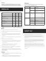
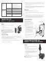
OWNERS MANUAL CONSTANT PRESSURE SYSTEMS, MECHANICAL PRESSURE SYSTEMS & TRANSFER PUMPS BLUELINE 101 INOX 230A EBS 45 BLUELINE 121 BLUETRON 101 CONTACT US BLUELINE 240 T 1300 798 022 [email protected] CONSTANT PRESSURE SYSTEMS BRISBANE 26 French Avenue, Brendale, Qld, 4500 MELBOURNE 24 Healey Rd, Dandenong South, Vic, 3175 T 1300 798 022 T 03 9706 9922 F 07 3881 2780 F 03 9706 9533. BLUEJET 111 MECHANICAL PRESSURE SYSTEMS INOX 250 TRANSFER PUMPS • INSTALLATION • OPERATION • TROUBLE SHOOTING • • INSTALLATION • OPERATION • TROUBLE SHOOTING • For any assistance or after sales service call Claytech on our toll free number 1300 798 022. Please have a look at further quality Claytech products at www.claytech.com.au For any assistance or after sales service call Claytech on our toll free number 1300 798 022. Please have a look at further quality Claytech products at www.claytech.com.au CL_SUB.OM_04.2012 Dear Customer, Troubleshooting Congratulations on purchasing this high quality Claytech product. Please take a minute to read these installation and important safety instructions before using your new equipment. Before performing any troubleshooting operation, it is necessary to disconnect the pump from the power supply by removing the pump systems plug from the electricity supply. TECHNICAL DATA Model Power Max. Head Max. Flow BlueJet101; BlueTron101; Blueline101 700 w 42 m 50 lpm Bluejet111; Bluetron111 800 w 42 m 60 lpm BlueJet121; Bluetron121; Blueline121 1000 w 49 m 60 lpm Inox230; Inox230A 800 w 35 m Inox240; Inox240A; Blueline240 1000 w 48 m Problem – Transfer pump Cause Corrective Action Pump does not start No power to unit. Check power outlet is turned on. Check electrical power is working. Shaft locked Unplug the pump and remove the blockage from pumps wet end. Pump does not prime or there is not enough water to pump Re-prime the pump, using the air bleed. Pump starts but does not pump water Make sure valve to tank is opened and not blocked. Verify that suction pipe and fittings are fixed tight and that water level is not below the pump level. Quantity being conveyed too little or none at all. Max. suction level exceeded Check suction level is suitable. 100 lpm Dirty suction filter Clean suction filter. 100 lpm Water level low Check suction valve is below water. Air in the pump housing Release air and check that all suction fittings are air tight. Inox250; Inox250A 1250 w 60 m 100 lpm EBS45 1000 w 45 m 85 lpm Caution • Before putting your pump unit into operation, thoroughly read and follow these instructions. • F or safety reasons, the pumping unit is not to be used by people who have not previously read the instructions. It is not to be used by children. • T he pump unit is only to be installed in an electrical supply conforming to Australian Electrical Regulations 2002. This must include a ln = 30mA safety switch. All electrical installations are to be performed by a Licensed Electrician. • T he pump unit is to be used for clean water with temperature below 35°C. The pump must not be allowed to freeze. • Do not raise, carry or fix the pump unit using the electrical cable. • T he pump must be covered. The pump unit is an electrical apparatus and therefore must be protected against moisture. The unit must be protected from rain, leaking fittings, water taps and / or any other form of water ingress or insect infestations. • It is strongly advised to secure the pump by bolting it down to a concrete slab or similar. • The pump unit must be positioned to avoid the possibility of it being flooded. • T he pump must not be used to pump salt water, sewage, flammable, corrosive or explosive liquids (e.g. petroleum oil, petrol, and thinners), grease, oils or foodstuffs. • P ump must to be installed in an easily accessible area and with plumbing fittings that make removal of pump for servicing possible. Suction Line 1. Minimum 1” gate valve or ball valve fitted to water tank. A ball valve is recommended for this application due to their superior reliability and fast action. 2. Y-Strainers are devices used to remove solids from flowing liquids by means of perforated stainless steel or wire mesh straining element. It must be installed on the suction side of the pump as shown in diagram. WARRANTY POLICY Clayton Engineering warrant this product for 2 years from the date of purchase. The warranty covers manufacturer’s defects in material or workmanship. The warranty does not cover malfunctions due to misuse or due to failure to follow the instructions in the instruction manual. Any alterations to the product are to be performed by a Clayton Engineering approved service agent. Any repairs performed by non approved personnel may void the warranty. To make a claim, contact Clayton Engineering, 26 French Ave, Brendale, Q, 4500 on phone 1300 798 022 or email [email protected]. You will be asked to provide proof of purchase and then will be instructed on the procedure for repairing or replacement of the product under warranty. All costs incurred for repair or replace, and additional claims can be discussed at this stage. This warranty is provided in addition to other rights and remedies you have under law: Our goods come with guarantees that cannot be excluded under the Australian Consumer Law. You are entitled to a replacement or refund for a major failure and for compensation for any other reasonably foreseeable loss or damage. You are also entitled to have the goods repaired or replaced if the goods fail to be of acceptable quality and the failure does not amount to a major failure. 1st January 2012. Pump starts and stops irregularly or continuously when using water. Quantity being conveyed too little or none at all. Pressure in reservoir to little Turn off pump. Open tap to let water pressure out. Turn off valve from water tank. Check air pressure in reservoir tank via air valve. Top air pressure up to 20 psi. Membrane is broken Replace membrane or complete air-tank. Max. suction level exceeded Check suction level is suitable. Dirty suction filter Clean suction filter. Water level low Check suction valve is below water. Air in the pump housing Release air and check that all suction fittings are air tight. 3. Suction line a minimum of 300mm of 25mm inside diameter flexible suction hose is recommended. Flexible hose will compensate for any movement in the installation. Avoid the use of elbows between the tank and the pump as these can cause cavitation. 4. L ocate the pump as close to the rainwater tank as possible, preferably at the base of the water tank so that the water level is always above the pump. If the pump is located above the level of the water than a one way valve must be installed on the end of the suction line. Discharge Line 1.The minimum recommended discharge line is 20mm inside diameter pipe. 2. If an elbow has to be fitted then install a 25mm inside diameter elbow first then use a reducer to over come friction loss. 3. W hen fitting a discharge line to a garden tap, ensure that the tap is attached to either a wall or post as a permanent fixture and with at least one metre of line between the pump and the tap, this will allow the controller to operate most efficiently. Do not install taps directly above pump as this can allow water to be discharged directly onto the pumps electric motor in the event of failure of the tap or connections. TRANSFER PUMPS ONLY Connect Controller to Pump BLUEJET 101, 111, 121, INOX 230, 240, 250 (Constant pressure systems only) Operation If you have selected a constant pressure system you will need to connect the pumps controller to the top of the pump.(Except the EBS45 this model has the pump controller built in) Transfer pumps have no pressure controller to make the pump turn on and off automatically. 1.Pump turns on when you turn on power. 2. Pump will only turn off when you turn off power supply. Pump must not be allowed to continue running if water supply is not available to pump or pump is running to closed outlet. You must manually switch power supply off to pump or you will cause damage to the pump. Starting – Transfer pump Before putting the system into operation, fill the pump and suction line with water to allow priming. Remove the priming plug to let air escape and water to fill pump. If the water level is below the level of the pump, ensure that the suction line is equipped with an anti-backflow foot or check valve. Open a tap slightly to allow the air to escape and the water to flow when the pump starts. 1. Connect the pump unit to the electrical power outlet and turn the power on. Pump will start pumping. 2. To stop the pump you must turn off power supply. 1. T hread the controller inlet (25mm connection at bottom of controller) to the the 25mm outlet on the top of the pump. Pumps either have a 25mm female outlet for the controller to thread into or those with a male outlet will have a connecting piece in the box to be used. Controller will only function correctly when fitted as per diagram, vertically on top of the pump. 2. C onnect the controllers electrical socket to the pumps three pin power plug. Delivery Line to House or Garden 25mm or larger Controller Priming Plug Rain Water Tank Pump Gate Valve ‘Y’ Strainer Suction Line 25mm or larger Drain Plug 3. C onnect the controllers three pin plug into power outlet. CONSTANT PRESSURE SYSTEMS ONLY BLUETRON 101, 111, 121, INOX 230A, 240A, 250A AND EBS45 Operation The controller on the pump makes the system automatic. The pump unit performs three functions: 1.Automatic pump operation: the pump starts when the tap is turned on and stops it about 10 seconds after the tap is turned off. 2. P ump protection from dry operation: The pump stops when there is no flow of water, thus preventing possible damage to the pump. This alarm is indicated by the LED called FAILURE on the front of the controller device. 3. Provides constant flow and pressure. The pumping unit will not work if the highest point of water delivery exceeds a vertical height of 15 meters. Starting Before putting the system into operation, fill the pump and suction line with water. Remove the priming plug to let air escape and water to fill pump. If the water level is below the level of the pump, ensure that the suction line is equipped with an anti-backflow check-valve and fill pump with water manually. Open a tap slightly to allow the air to escape and the water to flow when the pump starts. MECHANICAL PRESSURE SYSTEMS ONLY BLUELINE 101, BLUELINE 121 & BLUELINE 240 1. Connect the pump unit to the electrical power outlet and turn the power on. The ‘POWER’ LED will be on. Operation 2. T he pump starts automatically and the LED ‘ON’ will be on, indicating that the pump is operating. Allow the pump to operate for approximately 30 seconds to remove all air that may be in the system. 1.Automatic pump operation: when a tap is turned on water is supplied from the pressure tank, when it runs out the pump will turn on to supply water. When tap is turned off pump may still run for a while to replenish water in pressure tank. When pressure tank is filled pump will turn off. 3. Close the tap. The pump will stop in approximately 10 seconds. Auto-Restart and Dry-run protection If no water has been pumped due to priming problems or no water in tank, the ‘FAILURE’ LED will indicate and the controller will turn the pump off. After 24 hours, the pump will start automatically and repeat the process. It can be restarted by pressing the ‘RESET’ button, or by turning the 240v power ‘OFF’ and then ‘ON’ again at any time. LED light display code for EBS45 model only EBS45 is equipped with a display having 3 LEDs that indicate the operating status of the pump: Green LED: this lights as soon as pump is powered. Yellow LED: this lights when the pump is running and turns off when the pump stops.. Red LED: this lights when the pumps running is prevented due to lack of water or if the pump malfunctions. RESET button: this button is used to restart the pump after the flow of water has been restored. The electronic device is also equipped with an automatic reset that automatically attempts to restart the pump twice then after 1 hour, 5 hours and 20 hours. If the pump does not start, the electronics will permanently block. If this occurs turn off power and then turn on again. The device can be reset at any time by doing this before all attempts to restart have elapsed. Troubleshooting Before performing any troubleshooting operation, it is necessary to disconnect the pump from the power supply by removing the pump systems plug from the electricity supply. Problem – Constant pressure systems Cause Corrective Action Pump doesn’t stop when tap is closed There is a leak in the pipe system. (>1.2 lpm) Check all pipework for leaks on suction and discharge side of pump. Pressure test using a gauge if necessary. Any small leak from a connection, tap or leaking toilet will cause a problem. Pump starts but goes to failure (Failure light on) Pump does not prime or there is no water to pump Re-prime pump. Make sure there is sufficient water to pump and no blockage in suction line. Press RESET button and try operations again. Pump doesn’t start (No Power light) No power to unit Check power outlet is turned on. Check electrical connection (as per connecting controller section) and ensure electrical power is working. Pump starts and stops repeatedly There is a small leak in the system Check all pipework for leaks on suction and discharge side of pump. Pressure test using a gauge if necessary. Any small leak from a connection, tap or leaking toilet will cause a problem. 2. If water supply to pump runs out or is stopped, power to the pump must be turned off manually. Pump must not be allowed to run dry. Starting Before starting system, fill the pump and suction line with water to allow priming. Remove the priming plug to let air escape and water to fill pump. If the water level is below the level of the pump, ensure that the suction line is equipped with an anti-backflow foot valve. Open a tap slightly to allow the air to escape and the water to flow when the pump starts. • On mechanical pressure system a non return valve must be fitted onto the pumps inlet (suction side). • Air pressure in tank must be checked regularly and topped up if required. Air pressure in tank should be 20psi before you start pump. 1. Connect the pump unit to the electrical power supply and turn power on. 2. T he pump will start automatically. Allow the pump to operate for approximately 30 seconds to remove all air that may be in system. 3. Close the tap. The pump will continue pumping till pressure tank is full and then it will stop. 4. O pen up tap again and the pressure tank will provide water supply, when the pressure drops to the set low level, the pump will start up again. Troubleshooting Before performing any troubleshooting operation, it is necessary to disconnect the pump from the power supply by removing the pump systems plug from the electricity supply. Problem – Mechanical pressure system Cause Corrective Action Pump turns rapidly on and off when the tap is off Non-return valve not fitted to the front of the pump or is jammed open. Make sure non-return valve is fitted in correct position and is clear of any debris. Pump does not start No power to unit. Check power outlet is turned on. Check electrical power is working. Shaft locked Unplug the pump and remove blockage from pumps wet end. Pump does not prime or there is not enough water to pump Re-prime the pump, using the air bleed. Make sure valve to tank is opened and not blocked. Verify that suction pipe and fittings are fixed tight and that water level is sufficient. Pump starts but does not pump water