1
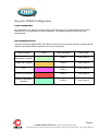
1S24 User Guide Arc Fault Monitoring System User Guide Visit www.rmspl.com.au for the latest product information. Due to RMS continuous product improvement policy this information is subject to change without notice. 1S24_Guide/Iss B/07/01/13 About This Manual This User Guide covers all 1S24 relays manufactured from February 2013. Earlier relays do not necessarily incorporate all the features described. Our policy of continuous development means that extra features & functionality may have been added. The 1S24 User Guide is designed as a generic document to describe the common operating parameters for all relays built on this platform. Some relay applications are described but for specific model information the individual “K” number Product / Test manuals should be consulted. The copyright and other intellectual property rights in this document, and in any model or article produced from it (and including any Registered or unregistered design rights) are the property of Relay Monitoring Systems Pty Ltd. No part of this document shall be reproduced or modified or stored in another form, in any data retrieval system, without the permission of Relay Monitoring Systems Pty Ltd, nor shall any model or article be reproduced from this document without consent from Relay Monitoring Systems Pty Ltd. While the information and guidance given in this document is believed to be correct, no liability shall be accepted for any loss or damage caused by any error or omission, whether such error or omission is the result of negligence or any other cause. Any and all such liability is disclaimed. Contact Us Relay Monitoring Systems Pty Ltd 2006-2013 6 Anzed Court • Mulgrave 3170 • AUSTRALIA Phone 61 3 8544 1200 • Fax 61 3 8544 1201 Email [email protected] • Web www.rmspl.com.au To download a PDF version of this guide: http://www.rmspl.com.au/userguide/1S24_user_guide.pdf To download the model specific Product Test Manual: http://www.rmspl.com.au/search.asp Part 1 How this Guide is Organised This guide is divided into four parts: Part 1 Overview Part 2 Documentation Part 3 Application Part 4 Commissioning Visit www.rmspl.com.au for the latest product information.Page Due to RMS continuous product improvement policy this information is subject to change without notice. 1S24_Guide/Iss B/07/01/13 Part 2 Documentation Technical Bulletin The detailed technical attributes, functional description & performance specifications for the 1S24 are described in the product Technical Bulletin. For the most up to date version go to: www.rmspl.com.au/handbook/1S24.pdf www.rmspl.com.au/handbook/1s30.pdf The order of precedence for product information is as follows: Product Test Manual (PTM) Technical Bulletin User Guide User Guide This User Guide covers all 1S24 relay versions & describes the generic features & attributes common across all versions. Different relay versions are required to cater for varying customer requirements such as auxiliary voltage range, I/O configuration, case style, relay functionality etc. The product ordering code described in the Technical Bulletin is used to generate a unique version of the relay specification & is called a Type Number. This code takes the form 1S24Kxx where the Kxx is the “K” or version number. For a complete description of the RMS “K” number system refer to: www.rmspl.com.au/handbook/parta3.pdf Product Test Manual Each 1S24 version has a specific PTM which provides details on the unique attributes of the relay. Each PTM includes the following information: Specific technical variations from the standard model if applicable Wiring diagram If you require a copy of the PTM for an RMS product the following options are available: Check the RMS web site at: www.rmspl.com.au/search.asp RMS CD catalogue select: List all Product/Test Manuals under Technical Library Contact RMS or a representative & request a hard copy or PDF by email. Visit www.rmspl.com.au for the latest product information.Page Due to RMS continuous product improvement policy this information is subject to change without notice. 1S24_Guide/Iss B/07/01/13 Part 3 Application Sensor Installation .......................................................................................................... 3 Sensor Spacing ..................................................................................................................................... 3 Sensor Placement ................................................................................................................................. 5 Sensor Mounting ................................................................................................................................... 5 Example Sensor Placement .................................................................................................................. 6 Scheme Wiring .............................................................................................................. 10 1S24 Connection diagram ................................................................................................................... 10 Terminal Layout and Module Dimensions ........................................................................................... 11 Custom Labels..................................................................................................................................... 12 Communications ........................................................................................................... 13 Physical Connections .......................................................................................................................... 13 IEC61850 Communication Topologies ................................................................................................ 14 IP Addressing ...................................................................................................................................... 15 1S24 Arc Fault Monitor Configuration ........................................................................ 16 Web Browser Session ......................................................................................................................... 16 Relay Build .......................................................................................................................................... 18 IP Configuration ................................................................................................................................... 19 Arc Configuration ................................................................................................................................. 20 State ........................................................................................................................................................ 20 Trip 1 ....................................................................................................................................................... 20 Trip 2 ....................................................................................................................................................... 21 Zone ........................................................................................................................................................ 21 Arc Status ............................................................................................................................................ 21 State ........................................................................................................................................................ 22 Flag ......................................................................................................................................................... 22 Count ....................................................................................................................................................... 22 Summary of 1S24 SARC Configuration .............................................................................................. 22 IEC61850 Substation Configuration ............................................................................ 23 Application Example ............................................................................................................................ 23 Arc Fault Scheme ................................................................................................................................ 24 1S24 SARC Allocation ........................................................................................................................ 26 Protection Zone Tripping ..................................................................................................................... 26 1S24 Source Arc Fault Detector Points .............................................................................................. 27 7SR22 Single Point Input GGIO Allocation ......................................................................................... 27 Creating An IEC61850 Project ............................................................................................................ 27 Populating IEDs In the IEC 61850 Project .......................................................................................... 30 System Configuration – Network View ................................................................................................ 36 System Configuration – Link View....................................................................................................... 39 Creating the 1S24 .cid File .................................................................................................................. 43 Page 1 Visit www.rmspl.com.au for the latest product information.Page Due to RMS continuous product improvement policy this information is subject to change without notice. 1S24_Guide/Iss B/23/07/12 1S24 IEC61850 Configuration ...................................................................................... 44 The .cid File ......................................................................................................................................... 44 FTP 1S24.cid File ................................................................................................................................ 44 Rebooting The 1S24 With The New 1S24.cid File .............................................................................. 46 Reyrolle 7SR22 Configuration ..................................................................................... 49 Logic Configuration ............................................................................................................................. 49 User Output Allocation ........................................................................................................................ 49 Current Check Logic ............................................................................................................................ 50 Binary Output Allocation For Circuit Breaker Tripping ........................................................................ 51 Device Synchronization ....................................................................................................................... 51 Monitor Indications ....................................................................................................... 52 Front Layout ........................................................................................................................................ 52 Power Up ............................................................................................................................................. 52 System Status ..................................................................................................................................... 53 Service Alarm ...................................................................................................................................... 53 Arc Sensor Indicators .......................................................................................................................... 54 Arc Sensor Circuit Supervision ............................................................................................................ 54 Arc Trip ................................................................................................................................................ 54 Global Arc Block .................................................................................................................................. 55 Flag Reset ........................................................................................................................................... 55 Reboot ................................................................................................................................................. 55 Reset To Factory Default .................................................................................................................... 56 Commissioning ............................................................................................................. 57 Commissioning Preliminaries .............................................................................................................. 57 Site Commissioning Verification Checklist .......................................................................................... 59 System Power Up .................................................................................................................................... 59 Sensor Failure Alarm Verification ............................................................................................................ 60 Arc Trip Testing ....................................................................................................................................... 61 Sensor Failure Alarm Trouble Shooting ................................................................................................... 62 ARC Trip Trouble Shooting...................................................................................................................... 62 General Ethernet Communications Trouble Shooting ............................................................................. 63 IEC61850 GOOSE Message Trouble Shooting ....................................................................................... 63 Interpreting Vx Auxiliary Supply or Relay Healthy Indications ................................................................. 64 Using IED SCOUT IEC61850 GOOSE Message Trouble Shooting ........................................................ 65 Page 2 Visit www.rmspl.com.au for the latest product information.Page Due to RMS continuous product improvement policy this information is subject to change without notice. 1S24_Guide/Iss B/23/07/12 Sensor Installation Sensor Spacing The 1S30 sensor is available as a single detector or dual detector package. The 1S30A single detector version is depicted below showing the location of the detection window and the approximate coverage zone : Detection window Coverage Zone 3m The recommended spacing for the 1S30A single detectors is approximately 5 - 6 m to ensure adequate detection overlap. 5-6m Page 3 Visit www.rmspl.com.au for the latest product information.Page Due to RMS continuous product improvement policy this information is subject to change without notice. 1S24_Guide/Iss B/23/07/12 The 1S30B Dual detector version provides an additional detection window for dual zones of coverage as depicted below : 6m Detection windows The recommended spacing for the 1S30B single detectors is approximately 5 - 6 m to ensure adequate detection overlap, this combination provides an overall coverage zone of approximately 10 12 m. 10 - 12m Page 4 Visit www.rmspl.com.au for the latest product information.Page Due to RMS continuous product improvement policy this information is subject to change without notice. 1S24_Guide/Iss B/23/07/12 The 1S30A and 1S30B sensors may also be mixed to provide various coverage combinations, again spacings of approximately 5 - 6 m should be observed to ensure adequate detection overlap. 10 - 12m Sensor Placement Sensors need to be mounted to provide full coverage of the switchgear cubicles to be protected. Where the protected zone is larger than the sensor coverage then the use of multiple sensors is required. Precise positioning of the sensors is generally not required as the light caused by the arc is reflected from the walls. Sensor Mounting The 1S30 is suitable for flush panel mounting in a number of configurations, for further information on mounting arrangements and mounting hardware refer to the 1S30 Technical Bulletin. Page 5 Visit www.rmspl.com.au for the latest product information.Page Due to RMS continuous product improvement policy this information is subject to change without notice. 1S24_Guide/Iss B/23/07/12 Example Sensor Placement The following are some typical examples of sensor placement. Sensor placement inside CB racking chamber Sensor placement inside busbar chamber Page 6 Visit www.rmspl.com.au for the latest product information.Page Due to RMS continuous product improvement policy this information is subject to change without notice. 1S24_Guide/Iss B/23/07/12 Sensor placement inside cable termination chamber Sensor placement for switchgear Busbar coverage (External through Hole Detector) Page 7 Visit www.rmspl.com.au for the latest product information.Page Due to RMS continuous product improvement policy this information is subject to change without notice. 1S24_Guide/Iss B/23/07/12 Sensor placement near Low Voltage Contactor for a Variable Speed Drive Sensor placement for Switchgear cable termination chamber (External through Hole Detector) Page 8 Visit www.rmspl.com.au for the latest product information.Page Due to RMS continuous product improvement policy this information is subject to change without notice. 1S24_Guide/Iss B/23/07/12 Sensor placement for end of Bus chamber (External through Hole Detector) Sensor placement for Switchgear cable termination chamber (External through Hole Detector) Page 9 Visit www.rmspl.com.au for the latest product information.Page Due to RMS continuous product improvement policy this information is subject to change without notice. 1S24_Guide/Iss B/23/07/12 Scheme Wiring 1S24 Connection diagram The above diagram shows the 1S24 connections. The connected sensor inputs need to be enabled and unused inputs disabled via the Web browser configuration tool. This is essential to : Allow connected sensor inputs to operate for an ARC Fault Allow connected sensor inputs to be supervised Ensure unconnected sensor inputs do not indicate an Arc sensor Alarm condition Page 10 Visit www.rmspl.com.au for the latest product information.Page Due to RMS continuous product improvement policy this information is subject to change without notice. 1S24_Guide/Iss B/23/07/12 Terminal Layout and Module Dimensions The module may be surface mounted or alternatively mounted on a din rail by using 2 optional din rail mounting kits (2 x RMS P/N: 290407157). Refer to the 1S24 Technical Bulletin for complete installation details. Page 11 Visit www.rmspl.com.au for the latest product information.Page Due to RMS continuous product improvement policy this information is subject to change without notice. 1S24_Guide/Iss B/23/07/12 Custom Labels The 1S24 front panel makes provision for two (2) custom labels, one label identifies the sensor location and the remaining label provides IED identification and IP address details. The default labels supplied with the relay may be marked up by hand or alternatively custom labels may be produced using the template provided on the RMS website, printed and slipped behind the clear windows on the front panel as depicted below. Page 12 Visit www.rmspl.com.au for the latest product information.Page Due to RMS continuous product improvement policy this information is subject to change without notice. 1S24_Guide/Iss B/23/07/12 Communications Physical Connections The 1S24 is ordered with either of the following Ethernet connection options : Standard Single Port : RJ45 10Base-T / 100Base-TX In the single port option the RJ45 port is utilised for connection to an IEC61850 station bus LAN for Goose messaging purposes and for device configuration. Optional Two Port : RJ45 10Base-T / 100Base-TX and Fibre 100Base-TX The two port option allows one of the ports to connect to an IEC61850 station bus LAN for Goose messaging purposes and either port may be utilised for device configuration. Page 13 Visit www.rmspl.com.au for the latest product information.Page Due to RMS continuous product improvement policy this information is subject to change without notice. 1S24_Guide/Iss B/23/07/12 IEC61850 Communication Topologies The 1S24 IED employs IEC61850 Goose messaging to convey the operation of ARC Fault Sensors and may be used with one or many subscribing IEDs to deploy ARC Fault protection schemes. The simplest application topology is to connect a single 1S24 directly with a single IED using a suitable crossover connection : 1S24 IED Alternatively the 1S24 or many 1S24 Arc Fault Monitors may be connected to a Station Bus Lan as shown below : IED1 1S241 IEC61850 Station Bus Lan IEDn 1S24n The Station Bus Lan may be arranged using many different topologies, discussion of the various Lan topologies is beyond the scope of this user guide. Page 14 Visit www.rmspl.com.au for the latest product information.Page Due to RMS continuous product improvement policy this information is subject to change without notice. 1S24_Guide/Iss B/23/07/12 IP Addressing The 1S24 IED will come preconfigured from the factory with the IP address 192.168.0.220. The default IP address may be used in a web browser session to undertake relay configuration. Full details of relay configuration are described in subsequent sections of the user guide. Reconfiguration of the 1S24 IP address may be required according to the IP addressing defined in the IEC61850 substation configuration, any subsequent web browser sessions will need to utilise the reconfigured IP address. Page 15 Visit www.rmspl.com.au for the latest product information.Page Due to RMS continuous product improvement policy this information is subject to change without notice. 1S24_Guide/Iss B/23/07/12 1S24 Arc Fault Monitor Configuration Web Browser Session Configuration of a 1S24 can be undertaken either via direct connection to a PC or via a Lan. If a direct connection to a PC is utilitised a crossover patch lead will be required to enable communication with the 1S24. Whether the communication is direct or via a Lan, both the PC and the 1S24 need to have IP addressing within the same network. With a subnet mask of 255.255.255.0 the first 3 octets of the IP address need to be the same for the PC and the 1S24 and the last octet needs to be unique, for example : 1S24 IP Address : 192.168.0.221 PC IP Address : 192.168.0.238 In the above example entering the 1S24 IP Address (192.168.0.221) into the PC web browser address field will establish a web browser session displaying the Relay Build Information and a menu tree to navigate to the other configuration screens. Page 16 Visit www.rmspl.com.au for the latest product information.Page Due to RMS continuous product improvement policy this information is subject to change without notice. 1S24_Guide/Iss B/23/07/12 To make any changes you will be prompted for a User name and Password The factory default username and password is : Username : admin Passworkd : RMS The username and password need only be entered once for each web server session and allows for multiple setting changes with access automatically timing out after 2 minutes of inactivity. Page 17 Visit www.rmspl.com.au for the latest product information.Page Due to RMS continuous product improvement policy this information is subject to change without notice. 1S24_Guide/Iss B/23/07/12 Relay Build The Relay Build screen provides device details such as the of the Serial Number and Firmware version. The Password may be changed at this point by entering your new password and pressing the Change button, enter the user name and previous password if prompted. Page 18 Visit www.rmspl.com.au for the latest product information.Page Due to RMS continuous product improvement policy this information is subject to change without notice. 1S24_Guide/Iss B/23/07/12 IP Configuration The IP Configuration screen displays and allows editing of the IP address parameters for the RJ45 port, Fibre port, Gateway and the SNTP Server. To change the IP address edit the IP address field and then click the Change button and enter the user name and password if prompted. Note that the Fibre port must be on a different IP network to the RJ45 port. For time stamping in accordance to the IEC61850 standard an SNTP server is required. The SNTP server IP address can be set in the IP Configuration screen but if left blank the 1S24 will attempt to find a default SNTP server if available. Page 19 Visit www.rmspl.com.au for the latest product information.Page Due to RMS continuous product improvement policy this information is subject to change without notice. 1S24_Guide/Iss B/23/07/12 Arc Configuration The Arc Configuration screen provides configuration settings for each of the 16 Sensor inputs. There are 4 settable parameters for each sensor input : State Armed or disabled, defines if the Sensor input is enabled or disabled, click on the field to change the state and enter the user name and password if prompted. Trip 1 Yes or No, determines if the Sensor input operates the Trip 1 output, click on the field to change the state and enter the user name and password if prompted. Page 20 Visit www.rmspl.com.au for the latest product information.Page Due to RMS continuous product improvement policy this information is subject to change without notice. 1S24_Guide/Iss B/23/07/12 Trip 2 Yes or No, determines if the Sensor input operates the Trip 2 output, click on the field to change the state and enter the user name and password if prompted. Zone The Zone Setting provides a means of improving Goose response time for simultaneous trips in a single Arc Fault tripping zone. The Zone setting ensures that a Goose is immediately broadcast without having to wait for the updating of all arc detectors in the same corresponding zone. Allowable Zone values are from 1 to 16. Set the Zone value the same for sensors located in the same zone. Click on the field to alter the Zone value. Arc Status The Arc Status screen provides status information on each of the of the 16 Sensor inputs. Page 21 Visit www.rmspl.com.au for the latest product information.Page Due to RMS continuous product improvement policy this information is subject to change without notice. 1S24_Guide/Iss B/23/07/12 State The State column determines the state of each sensor input. The following states are reported : Disabled Armed Tripped Failed ARC Sensor is disabled ARC Sensor is armed ARC detected (changes for the period of the trip) ARC sensor supervision failure Initializing Stuck ARC sensor initializing (transitory) ARC sensor stuck on Flag The Flag column will indicate and latch for an Arc Sensor operation, individual Flags may be reset by clicking on the sensor flag status and entering the user name and password if prompted. Count The Count field provides a log of ARC sensor operations since power on or the last counter reset, the individual sensor counters may be reset to 0 by clicking on the count field and entering the user name and password if prompted. Summary of 1S24 SARC Configuration The following steps outline the 1S24 SARC Configuration : Establish a Web Browser session using the default IP address Set up the IP addressing for the SNTP server Arm the ARC Sensor inputs to be utilised in the application Set which outputs are to be operated by the respective ARC sensors Page 22 Visit www.rmspl.com.au for the latest product information.Page Due to RMS continuous product improvement policy this information is subject to change without notice. 1S24_Guide/Iss B/23/07/12 IEC61850 Substation Configuration Application Example The following example will demonstrate the process of implementing an ARC Fault Protection scheme using IEC61850 Goose massaging in conjunction with other IEC61850 equipped IEDs. The example will comprise of a 1S24 Arc Fault Monitor used in conjunction with Reyrolle 7SR22 Argus relays with IEC61850 communications and implemented with the Reydisp Manager productivity tool embedded with the optional Digsi System configurator. A similar process is equally applicable to IEC61850 equipped IEDs from alternative vendors and alternative System Configuration tools. The steps to implement our Application Example are : Create an IEC61850 project in a System configurator Populate the project with the Application IEDs Populate the project with the 1S24 IEDs using the default 1S24 icd file Populate the project with the IEC61850 Substation Using the System Configurator configure the desired IP addressing of the subnet containing all of the application IEDs With the System Configurator create the GOOSE applications with the associated GOOSE linkages between the source IED logical nodes (in the case of the 1S24 : SARCs) and the subscribing IED (in our example we use GGIO) With all GOOSE mapping complete create a .cid file for the 1S24 using the export facility in the System Configurator FTP the 1S24 .cid file into the 1S24 Reboot the 1S24 to invoke the GOOSE mapping Create the subscribing relay application logic that will make use of the status changes in the subscribed GOOSE messages from the 1S24 Send the relay configurations as well as IEC 61850 to the respective subscribing IEDs in the application Page 23 Visit www.rmspl.com.au for the latest product information.Page Due to RMS continuous product improvement policy this information is subject to change without notice. 1S24_Guide/Iss B/23/07/12 Arc Fault Scheme The single line schematic arrangement of the application example is shown in the diagram below: TR1 TR1 LT CB Feeder 1A CB Arc Fault coverage is to be provided to the bus, circuit breaker chambers and cable termination chambers and shall be current checked with an overcurrent relay. Tripping shall be zoned to provide sectionalising and minimise affected plant. Page 24 Visit www.rmspl.com.au for the latest product information.Page Due to RMS continuous product improvement policy this information is subject to change without notice. 1S24_Guide/Iss B/23/07/12 The proposed scheme is as follows: TR1 Upstream Trip Hardwired or Goose SARC Goose 7SR22 Downstream Trip Hardwired or Goose Sensor connections to 1S24 1S24 The scheme comprises of 1S30 sensors connected to a 1S24 Arc Fault Monitor, providing ARC Fault coverage of the coloured protection zones. The 1S24 provides the SARC Logical Node for the operation of Arc Fault Sensors. The 7SR22 Overcurrent relay subscribes to SARC Goose messages and initiates the required protection tripping via an Overcurrent Check. Tripping in this case will be carried out by hardwiring to respective circuit breakers and using binary outputs from the 7SR22 IED but could also be implemented via Goose by another subscribing IED. Flexible tripping logic may be implemented in the 7SR22 according to specific application requirements and may also accommodate different operating arrangements in more complex applications. Page 25 Visit www.rmspl.com.au for the latest product information.Page Due to RMS continuous product improvement policy this information is subject to change without notice. 1S24_Guide/Iss B/23/07/12 1S24 SARC Allocation In the proposed scheme we have 6 Arc Fault Sensors installed providing coverage for 5 distinct protection zones. The individual SARCs are allocated as follows : Zone Coverage Colour Number of Sensors SARC Allocation Feeder Exit Termination Chamber 1 SARC 1 Feeder CB Chamber 1 SARC 2 Bus 2 SARC 3 SARC 4 Incomer CB Chamber 1 SARC 5 Incomer Termination Chamber 1 SARC 6 Protection Zone Tripping The required circuit breaker tripping is defined by the following tripping table : SARC Operation Zone Coverage Colour Trip SARC 1 Feeder Exit Termination Chamber 1A CB SARC 2 Feeder CB Chamber TR1 LT CB SARC 3 or SARC 4 Bus TR1 LT CB SARC 5 Incomer CB Chamber Upstream SARC 6 Incomer Termination Chamber Upstream Page 26 Visit www.rmspl.com.au for the latest product information.Page Due to RMS continuous product improvement policy this information is subject to change without notice. 1S24_Guide/Iss B/23/07/12 1S24 Source Arc Fault Detector Points The 1S24 will broadcast the following Arc Fault Detector Points to subscribing IEDs : Source ARC Fault IED Goose ARC Fault Detector points Function SARC SARC1 RMS_1S24/DEV_1S24/RMS_SARC1/FADET SARC2 RMS_1S24/DEV_1S24/RMS_SARC2/FADET SARC3 RMS_1S24/DEV_1S24/RMS_SARC3/FADET SARC4 RMS_1S24/DEV_1S24/RMS_SARC4/FADET SARC5 RMS_1S24/DEV_1S24/RMS_SARC5/FADET SARC6 RMS_1S24/DEV_1S24/RMS_SARC6/FADET Description 1S24 Arc Fault Detector 1 1S24 Arc Fault Detector 2 1S24 Arc Fault Detector 3 1S24 Arc Fault Detector 4 1S24 Arc Fault Detector 5 1S24 Arc Fault Detector 6 7SR22 Single Point Input GGIO Allocation The 7SR22 relay will subscribe to SARC Goose messages broadcast by the 1S24 IED and shall assign subscribed SARCs to Single Point Input GGIO as follows : Destination 7SR22 Relay Goose Single Point Inputs ARC Fault Detectors Function Single Point Input SARC1 CBn/CTRL/SPi64GGIO1/SPCSO1 SARC2 CBn/CTRL/SPi64GGIO1/SPCSO2 SARC3 CBn/CTRL/SPi64GGIO1/SPCSO3 SARC4 CBn/CTRL/SPi64GGIO1/SPCSO4 SARC5 CBn/CTRL/SPi64GGIO1/SPCSO5 SARC6 CBn/CTRL/SPi64GGIO1/SPCSO6 Description CBn Single Point Input 1 Data CBn Single Point Input 2 Data CBn Single Point Input 3 Data CBn Single Point Input 4 Data CBn Single Point Input 5 Data CBn Single Point Input 6 Data Creating An IEC61850 Project To create and configure an IEC61850 project requires an IEC61850 system configurator. In our example Reydisp Manager with the optional embedded Digsi system configurator will be used to establish the Goose message linkages between the 1S24 and the 7SR22 Overcurrent relay. Reydisp Manager is used as the productivity tool to manage the IEC61850 configuration process for Reyrolle relays and may also be utilised to create any required logic in Reyrolle devices. Page 27 Visit www.rmspl.com.au for the latest product information.Page Due to RMS continuous product improvement policy this information is subject to change without notice. 1S24_Guide/Iss B/23/07/12 A screenshot of Reydisp Manager is shown below : To create a new project choose File and New. Page 28 Visit www.rmspl.com.au for the latest product information.Page Due to RMS continuous product improvement policy this information is subject to change without notice. 1S24_Guide/Iss B/23/07/12 Fill in the details including where you want the project file to be stored and hit OK. The new project has been created. Page 29 Visit www.rmspl.com.au for the latest product information.Page Due to RMS continuous product improvement policy this information is subject to change without notice. 1S24_Guide/Iss B/23/07/12 Populating IEDs In the IEC 61850 Project We now need to populate the project with our IEDs, firstly the Reyrolle 7SR22. Choose Insert and Device and you will be presented with the following screen. Select the required relay, for this example we will choose a 7SR2202-2AA77-0CA0 ensure that the MLFB code is correctly filled. Once the MLFB codes is correctly filled you can then select the device. Page 30 Visit www.rmspl.com.au for the latest product information.Page Due to RMS continuous product improvement policy this information is subject to change without notice. 1S24_Guide/Iss B/23/07/12 The 7SR22 IED has been added to your project. Continue adding Reyrolle IEDs as required using the same process. Nominate a meaningful IED name for each IED by right clicking on the IED and choosing properties. Page 31 Visit www.rmspl.com.au for the latest product information.Page Due to RMS continuous product improvement policy this information is subject to change without notice. 1S24_Guide/Iss B/23/07/12 Choose the IEC 61850 tab and enter a name in the IED Name field. Next we will add the RMS 1S24 IED which is added as a Third Party ICD File. You will need to have the 1S24 ICD file which is available through RMS. Choose Insert and Third Party ICD File and you will be presented with the following file selection, choose the ICD file that has been supplied by RMS. Page 32 Visit www.rmspl.com.au for the latest product information.Page Due to RMS continuous product improvement policy this information is subject to change without notice. 1S24_Guide/Iss B/23/07/12 The 1S24 IED has now been added to your project. You can nominate a meaningful IED name for the 1S24 IED by right clicking on the IED and choosing properties. Now we will add a IEC61850 Station, choose Insert and Station. Page 33 Visit www.rmspl.com.au for the latest product information.Page Due to RMS continuous product improvement policy this information is subject to change without notice. 1S24_Guide/Iss B/23/07/12 We can give the Station a meaningful name by editing the Item Name. We then nominate the Station Devices to be included in the Station by right clicking on the Station and choosing properties. Select Station Devices and you will see a selection of available unassigned IEDs Page 34 Visit www.rmspl.com.au for the latest product information.Page Due to RMS continuous product improvement policy this information is subject to change without notice. 1S24_Guide/Iss B/23/07/12 Select the IEDs Press Add to Station. Press OK to Assign the Devices to the Station. Page 35 Visit www.rmspl.com.au for the latest product information.Page Due to RMS continuous product improvement policy this information is subject to change without notice. 1S24_Guide/Iss B/23/07/12 System Configuration – Network View We now need to configure the IP Addressing for our Station LAN and the Goose Linkages for our Goose messages. With the Station highlighted Double Click the System Configurator Button, this will start the Digsi System Configurator in the Network view. Expanding the RMS Station will present the Subnets associated with the Station. Page 36 Visit www.rmspl.com.au for the latest product information.Page Due to RMS continuous product improvement policy this information is subject to change without notice. 1S24_Guide/Iss B/23/07/12 Clicking on the Subnet will reveal the IP Start address, Subnet mask and standard gateway settings. We can set the IP start address for our network for convenience, in this case 192.168.0.1. The Standard Gateway may also be set at this point if one exists. Page 37 Visit www.rmspl.com.au for the latest product information.Page Due to RMS continuous product improvement policy this information is subject to change without notice. 1S24_Guide/Iss B/23/07/12 Expanding Subnet1 will reveal the IEDs that we previously assigned to the Station. The individual devices may be selected to set their IP addresses. Alternatively at the Subnet level the IP addressing may be automatically allocated starting at the IP start address previously set for the Subnet by pressing the auto IP button. Page 38 Visit www.rmspl.com.au for the latest product information.Page Due to RMS continuous product improvement policy this information is subject to change without notice. 1S24_Guide/Iss B/23/07/12 We’ll choose to auto allocate the IP addressing, the result is shown below with the the IP address of each device being incremented and unique. System Configuration – Link View With the network addressing having been completed we’ll now create our GOOSE applications and associated GOOSE linkages. The screenshot below shows the link view with the RMS Station : Page 39 Visit www.rmspl.com.au for the latest product information.Page Due to RMS continuous product improvement policy this information is subject to change without notice. 1S24_Guide/Iss B/23/07/12 The Applications window lists all the applications by Station, drilling down into the RMS station will reveal the Subnets and any associated reports or GOOSE applications. An existing GOOSE application may be used or alternatively a New GOOSE application created. For our example we’ll use the existing GOOSE application 1, selecting this application reveals the associated IEDs as sources and destinations. Expanding the respective IEDs in the Sources and Destinations windows will show the Logical Nodes and their associated Data Objects. Page 40 Visit www.rmspl.com.au for the latest product information.Page Due to RMS continuous product improvement policy this information is subject to change without notice. 1S24_Guide/Iss B/23/07/12 Firstly we’ll select the RMS_1S24 IED and expand RMS_SARC1 and choose FADet to Add as a Source. Once Added as a source it will appear in the interconnections. In turn add all of the required source SARCs. Page 41 Visit www.rmspl.com.au for the latest product information.Page Due to RMS continuous product improvement policy this information is subject to change without notice. 1S24_Guide/Iss B/23/07/12 The SARCs are linked to the respective 7SR22 IED Single Point Input GGIO chosen from the Destinations window (refer also to the Allocation table in the earlier part of this example). With the linkages complete save and exit the Digsi System configurator. Page 42 Visit www.rmspl.com.au for the latest product information.Page Due to RMS continuous product improvement policy this information is subject to change without notice. 1S24_Guide/Iss B/23/07/12 Creating the 1S24 .cid File We know need to create a .cid file which we will use at a later stage of the IED Configuration process. Note : The following highlighted steps are required to address a particular idiosyncrasy of Digsi : 1. Open the Station in Reydisp Manager, go to the link screen and make a change to a linkage and save the project. 2. Ensure you then revert the linkage back to original and save the project again. Now go to the Network screen, select the 1S24 IED, right click and select Export IEC61850 device configuration. Save the file for later 1S24 configuration. System configuration is now complete. Page 43 Visit www.rmspl.com.au for the latest product information.Page Due to RMS continuous product improvement policy this information is subject to change without notice. 1S24_Guide/Iss B/23/07/12 1S24 IEC61850 Configuration The .cid File The 1S24 requires a .cid file that incorporates the IEC61850 Substation Project Configuration including the Report datasets that must be sent and where they are sent to. The Project Configuration is contained in the .cid file for the 1S24 created earlier from our Substation configuration process example and needs to be loaded into the 1S24 IED. FTP 1S24.cid File We will be using the Beck’s @CHIPTOOL software utility to establish a terminal session with the 1S24 and to FTP the .cid file. Download @CHIPTOOL for free from : http://www.beck-ipc.com/en/download/licence.asp?id=chiptool_install&l=1 Run @CHIPTOOL on the PC. The Tool will detect any 1S24 devices on the network as seen by the screen shot below : Page 44 Visit www.rmspl.com.au for the latest product information.Page Due to RMS continuous product improvement policy this information is subject to change without notice. 1S24_Guide/Iss B/23/07/12 With the 1S24 selected in the @CHIPTOOL screen we will establish an FTP session by choosing Tools and FTP-Client. Enter the following Username and Password for the FTP session : User : ftp Password : ftp You will be presented with 2 file directories, the left side is the source directory and the right side A:/ is the 1S24. Locate and select the saved 1S24.cid file created earlier, right click on the file and copy it to the A:/ drive. Page 45 Visit www.rmspl.com.au for the latest product information.Page Due to RMS continuous product improvement policy this information is subject to change without notice. 1S24_Guide/Iss B/23/07/12 Once copied, ensure that any existing 1S24.cid file in the A:/ drive is renamed or deleted (right click on the file for renaming deletion options). Then select the copied file in the A:/ drive, right click and ensure it is renamed as 1S24.cid. Rebooting The 1S24 With The New 1S24.cid File A reboot of the 1S24 is required once the new 1S24.cid file has been loaded. The reboot can be done either via powering down and repowering the device or by pressing and holding the Flag Reset button for about 5 sec until all the LEDs start flashing, refer to Reboot under Monitor Indications. Alternatively you can set up a terminal session to reboot the 1S24 using @CHIPTOOL. Using @CHIPTOOL select the 1S24 and choose Tools and Terminal. Enter the following Username and Password for the terminal session : Page 46 Visit www.rmspl.com.au for the latest product information.Page Due to RMS continuous product improvement policy this information is subject to change without notice. 1S24_Guide/Iss B/23/07/12 User : tel Password : tel Use CTRL-F to check the context. You need to be in Shell. CTRL-F to switch the context to Shell. Page 47 Visit www.rmspl.com.au for the latest product information.Page Due to RMS continuous product improvement policy this information is subject to change without notice. 1S24_Guide/Iss B/23/07/12 Press enter to make the command prompt visible. Type in Reboot at the command prompt, the 1S24 will now restart and the LEDs indicate per a normal power up, refer to Power Up - Monitor Indications. When all the LEDs stop flashing the 1S24 configuration is complete. Page 48 Visit www.rmspl.com.au for the latest product information.Page Due to RMS continuous product improvement policy this information is subject to change without notice. 1S24_Guide/Iss B/23/07/12 Reyrolle 7SR22 Configuration Logic Configuration Our application is to employ a current check using the pickup of an Instantaneous Overcurrent Element (50-1) to qualify an Arc Sensor operation. The following sections outline the logic implemented. User Output Allocation Using the previously defined ARC Fault Sensor Zones we will nominate the User Outputs that will capture the resultant SARC operation and current check logic. Zone Coverage Colour SARC Allocation User Output Feeder Exit Termination Chamber SARC 1 User Output 1 Feeder CB Chamber SARC 2 User Output 2 Bus SARC 3 SARC 4 User Output 2 Incomer CB Chamber SARC 5 User Output 3 Incomer Termination Chamber SARC 6 User Output 3 Page 49 Visit www.rmspl.com.au for the latest product information.Page Due to RMS continuous product improvement policy this information is subject to change without notice. 1S24_Guide/Iss B/23/07/12 Current Check Logic The SARC GOOSE Trips are qualified by the SARC quality and a current check in our current check logic. The quality bit can be used for blocking purposes such as testing or isolations. Page 50 Visit www.rmspl.com.au for the latest product information.Page Due to RMS continuous product improvement policy this information is subject to change without notice. 1S24_Guide/Iss B/23/07/12 Binary Output Allocation For Circuit Breaker Tripping The following User Output to Binary Output allocations complete our ARC Fault Trip with Current Check. SARC Operation Zone Coverage User Output Binary Output Trip SARC 1 Feeder Exit Termination Chamber User Output 1 BO2 1A CB SARC 2 Feeder CB Chamber User Output 2 BO3 TR1 LT CB SARC 3 or SARC 4 Bus User Output 2 BO3 TR1 LT CB SARC 5 Incomer CB Chamber User Output 3 BO4 Upstream SARC 6 Incomer Termination Chamber User Output 3 BO4 Upstream The screenshot shows the User Output to Binary Output allocation in the setting editor of Reydisp Manager. Complete any other Protection settings otherwise required and save your setting. Device Synchronization With all IED settings, IED Logic and IEC61850 configuration complete we now need to Synchronize the device. Reydisp Manager will manage the file transfer process to the 7SR22 IED and upon completion the 7SR22 will be able subscribe to SARC Goose messages from the 1S24 IED. Page 51 Visit www.rmspl.com.au for the latest product information.Page Due to RMS continuous product improvement policy this information is subject to change without notice. 1S24_Guide/Iss B/23/07/12 Monitor Indications Front Layout The picture below depicts the indications provided on the front of the Arc Fault Monitor. Power Up When powering up, all the Leds will flash once and then extinguish and then in turn sequentially illuminate 1 led at a time until all Leds are illuminated – the sequence takes about 14 secs during the boot cycle. When the boot cycle is complete the 1S24 will indicate the current state. Page 52 Visit www.rmspl.com.au for the latest product information.Page Due to RMS continuous product improvement policy this information is subject to change without notice. 1S24_Guide/Iss B/23/07/12 System Status Auxiliary Supply or Relay Healthy Indication LED State On Solid Fast Flashing (approx three times every sec) Slow Flashing (approx once every sec) Off Meaning Healthy CID loading error SNTP sync fail Internal Communications failure Refer to the Commissioning section : Interpreting Vx Auxiliary Supply or Relay Healthy Indications for further details Ethernet Activity Service Alarm The module self supervision checks the following : Auxiliary supply failure Internal supply rail is outside acceptable limits CPU Hardware watchdog failure Service Alarm Page 53 Visit www.rmspl.com.au for the latest product information.Page Due to RMS continuous product improvement policy this information is subject to change without notice. 1S24_Guide/Iss B/23/07/12 Arc Sensor Indicators Indicate solid when an Arc Sensor has detected an Arc, the LEDs are reset after pressing the Flag Reset. 16 Arc Sensor Indicators A flashing Arc Sensor LED indicates a failure of the sensor, refer to the Sensor Alarm indicator description. Arc Sensor Circuit Supervision Indicates solid when an Arc Sensor has faulted either due to an open circuit, sustained short circuit ( >10 sec ) or high ambient lighting. Sensor Alarm The affected sensor will be indicated by its front panel sensor LED 1-16 flashing. The Sensor Alarm will self reset upon the fault conditions being corrected. Arc Trip Indicates solid when the respective assigned self reset Arc Trip contacts operate. The LEDs reset when the Arc Trip contacts self reset. Arc Trip Page 54 Visit www.rmspl.com.au for the latest product information.Page Due to RMS continuous product improvement policy this information is subject to change without notice. 1S24_Guide/Iss B/23/07/12 Global Arc Block Indicates solid when the Global Arc Block input is energised, all Arc Trips are blocked (61850 and Arc Trip outputs). Global Arc Block Flag Reset To reset the ARC Sensor LEDs The ARC sensor LEDs may also be reset by energising the binary input Reboot A reboot is achieved by applying power to the relay, all the Leds will flash once and then extinguish and then in turn sequentially illuminate 1 led at a time until all Leds are illuminated – the sequence takes about 14 secs. Alternatively if the relay is powered, hold down the Flag Reset button for about 5 sec until all of the Leds (except Service) start flashing, then release the Flag Reset button. The LEDs will continue to flash for approx 9 secs and then extinguish and then in turn sequentially illuminate 1 led at a time until all Leds are illuminated – the sequence takes another 14 secs approx. The reboot must be used after loading in new .icd files into the IED and restarting the software process with the new 61850 configurations. The reboot may also be required if for some reason the 1S24 does not respond to web server commands or becomes unresponsive to ftp or terminal sessions. Page 55 Visit www.rmspl.com.au for the latest product information.Page Due to RMS continuous product improvement policy this information is subject to change without notice. 1S24_Guide/Iss B/23/07/12 Reset To Factory Default With the relay unpowered, hold down the Flag Reset button and power up the relay. After releasing the reset button all of the Leds (except Service) will flash once and then extinguish and then in turn sequentially illuminate 1 led at a time until all Leds are illuminated – the sequence takes another 14 secs approx. The Cold Boot is used for reverting the IED back to factory default settings including default passwords. Page 56 Visit www.rmspl.com.au for the latest product information.Page Due to RMS continuous product improvement policy this information is subject to change without notice. 1S24_Guide/Iss B/23/07/12 Part 4 Commissioning Commissioning Preliminaries Carefully examine the module to ensure that no damage has occurred during transit. Check that the model number and rating information are correct. Insulation The relay, and its associated wiring, may be insulation tested between: - all electrically isolated circuits - all circuits and earth An electronic or brushless insulation tester should be used, having a dc voltage not exceeding 1000V. Accessible terminals of the same circuit should first be strapped together. Deliberate circuit earthing links, removed for the tests, subsequently must be replaced. ARC Trip Verification ARC Trip Verification will require a flash source to initiate sensor operation. A high powered photographic flash is the most convenient means of initiating positive sensor operation. Note that mobile phone or small compact camera flashes may not have sufficient power to cause sensor operation. The RMS ‘Arc Flash Timing Test Guide’ outlines a suggested test setup to provide a flash source and determine ARC Trip times. The ‘Arc Flash Timing Test Guide’ is available on the RMS website: www.rmspl.com.au/userguide/arc_flash_timing_test_guide.pdf Page 57 Visit www.rmspl.com.au for the latest product information.Page Due to RMS continuous product improvement policy this information is subject to change without notice. 1S24_Guide/Iss B/23/07/12 Arc only tests are conducted as per the section ‘Timing test of 1S25 (no current check)’ substituting the wiring for the 1S25 with equivalent wiring for the 1S24. Current check tests are conducted as per the section ‘Timing test of 1S26’, with the 1S30 connected to the 1S24, the current source connected to the current check relay and the 1S24 and subscribing current check relay connected via a IEC61850 Station Bus Lan for the transfer of Goose messages. The ‘Arc Flash Timing Test Guide’ only requires the use of a conventional test set, end users may also find it beneficial to have access to a IEC61850 equipped test set which can aid in the observation of GOOSE traffic, undertaking GOOSE timing tests and trouble shooting. Page 58 Visit www.rmspl.com.au for the latest product information.Page Due to RMS continuous product improvement policy this information is subject to change without notice. 1S24_Guide/Iss B/23/07/12 Site Commissioning Verification Checklist Observe all site specific standard safety procedures. The following tests are undertaken following the completion of all 1S24 ARC Monitor and Overcurrent Relay IEC61850 Substation Configuration and associated IED configurations, scheme wiring and the wiring of all 1S30 sensors. System Power Up Item 1 2 3 4 5 6 7 8 9 10 11 12 13 14 Description Complete Confirm all necessary primary equipment isolations Confirm all necessary secondary equipment isolations (including trip outputs) Check fitment of 1S30 optical sensors and cable condition Check panel installation of the 1S24 monitor Check for correct case earthing Check the 1S24 is wired to the protection design schematic, connected to a Substation LAN and confirm all IEC61850 configurations Confirm Fail alarm relay is closed (Terminals 25 and 26) Apply correct Auxiliary voltage to power up the 1S24 Upon power up the relay enters a relay boot cycle, all the Leds will flash once and then extinguish and then in turn sequentially illuminate 1 led at a time until all Leds are illuminated – the sequence takes about 14 secs. Observe that the green power LED remains illuminated solid after the relay boot cycle. Confirm Fail alarm relay is open (Terminals 25 and 26) and the associated LED is extinguished Using a web browser check 1S24 configuration settings match protection setting specifications Confirm that the Arc Sensor fail alarm LED remains off and none of the sensor LEDs are flashing (Refer Sensor Failure Trouble shooting if a sensor fail is indicated) Confirm all Sensor LED’s remain OFF Confirm the Ethernet LED is showing activity Page 59 Visit www.rmspl.com.au for the latest product information.Page Due to RMS continuous product improvement policy this information is subject to change without notice. 1S24_Guide/Iss B/23/07/12 Sensor Failure Alarm Verification Item 1 2 3 4 5 6 7 8 Description Complete Disconnect each sensor from the associated 1S24 sensor input Confirm the associated sensor LED flashes, the Sensor Alarm LED illuminates and operation of the Relay Fail Alarm output contact Reconnect each sensor back to the associated 1S24 sensor input Confirm the associated sensor Fail indications clear and the Relay Fail Alarm output contact opens In turn short across each 1S24 sensor input Confirm the associated sensor LED flashes, the Sensor Alarm LED illuminates and operation of the Relay Fail Alarm output contact Remove the short on each 1S24 sensor input Confirm the associated sensor Fail indications clear and the Relay Fail Alarm output contact opens Page 60 Visit www.rmspl.com.au for the latest product information.Page Due to RMS continuous product improvement policy this information is subject to change without notice. 1S24_Guide/Iss B/23/07/12 Arc Trip Testing Item 1 2 3 4 5 Description Complete Initiate the operation of each sensor by the use of a suitably powered camera flash * If a current check interlock is employed in your ARC Fault protection scheme ensure that current is injected into the associated Overcurrent relay to cause operation of the current check element at the same time the sensor is flashed Check operation of the corresponding sensor LED and the arc fault trip output contacts Confirm that the subscribing IED has received the GOOSE SARC from the 1S24 View the web browser settings of the 1S24 to explain any unexpected behavior Confirm operation of Flag Reset after each tripping operation. Repeat ARC trips and confirm correct operation of remote reset using the web browser Refer also to the RMS ‘Arc Flash Timing Test Guide’ for a suggested test setup to provide a flash source and determine ARC Trip times. The ‘Arc Flash Timing Test Guide’ is available on the RMS website : www.rmspl.com.au/userguide/arc_flash_timing_test_guide.pdf Apply a Global ARC Fault block. Item 1 2 3 Description Complete Initiate the operation of each sensor by the use of a suitably powered camera flash Confirm blocking of the arc fault trip output contacts Confirm blocking of the SARC GOOSE messages from the 1S24 Page 61 Visit www.rmspl.com.au for the latest product information.Page Due to RMS continuous product improvement policy this information is subject to change without notice. 1S24_Guide/Iss B/23/07/12 Sensor Failure Alarm Trouble Shooting Item 1 2 3 4 Description Complete If any arc sensor LED’s are flashing re-check the 1S30 wiring integrity Check that the sensors are wired to the correct sensor inputs Using a web browser session check that the correct sensor inputs are enabled and any unused sensor inputs are disabled If the Sensor Alarm persists disable all of the sensor inputs and check that all Sensor Alarm indications are extinguished ARC Sensor Supervision Trouble Shooting Item 1 2 3 Description Complete If there is a Sensor Alarm indication re-check the 1S30 wiring integrity Check that the sensors are connected to the correct arc sensor inputs and check that the correct sensor inputs are enabled and unused inputs are disabled Check for high ambient lighting conditions for all the sensors ARC Trip Trouble Shooting If an arc trip occurs without an ARC being present this indicates either: - a very high ambient light condition is triggering a sensor or - short circuit wiring of a 1S30 sensor In both cases if the condition persists the Supervision output will operate after a 10 sec delay. Item 1 2 Description Check the 1S30 wiring integrity of the sensors Check for high ambient lighting conditions for all the sensors Complete Page 62 Visit www.rmspl.com.au for the latest product information.Page Due to RMS continuous product improvement policy this information is subject to change without notice. 1S24_Guide/Iss B/23/07/12 General Ethernet Communications Trouble Shooting If you are having trouble communicating with the 1S24 IED or other subscribing IEDs check the following: Item 1 2 3 4 Description Complete Check that the Station Bus Lan is active and functioning Check that the 1S24 IED and the subscribing IED Ethernet ports are active and communicating by checking the port activity LEDs Undertake a ping test on the 1S24 IED and the subscribing IEDs Confirm the IP addressing for each of the devices is correct as determined by the Substation topology (check the devices are on the same Subnet) and that devices connected on the same Subnet have unique addresses IEC61850 GOOSE Message Trouble Shooting If a SARC GOOSE is not being received by a subscribing IED check the following: Item 1 2 3 4 5 6 7 Description Complete Check that the required SARC is enabled in the 1S24 For a current check scheme is the current check element enabled and being picked up? Check the GOOSE linkages in the Substation Project and ensure that the correct sources and subscriptions have been established Check that the Subscribing IED logic is consistent with the Subscribed SARC. If required troubleshoot the logic by observing the individual incoming signals are consistent with your test conditions for example Is the correct GGIO being received? Is the quality bit being correctly treated? Is the current check qualification being asserted Using the 1S24 Web Browser check for any error messages on the Status screen when you FTP the .cid file into the device In the Web Browser observe the trip status when a Sensor is triggered Using and IEC61850 browser such as IED Scout observe the trip status changes in the 1S24 ICD Page 63 Visit www.rmspl.com.au for the latest product information.Page Due to RMS continuous product improvement policy this information is subject to change without notice. 1S24_Guide/Iss B/23/07/12 Interpreting Vx Auxiliary Supply or Relay Healthy Indications The Healthy LED will be illuminated solid to indicate normal operation of the 1S24. The Healthy LED is also utilised to indicate error conditions to assist in troubleshooting. The following table summarises all Healthy LED indications : LED State Meaning Healthy On Solid Fast Flashing (approx three times every sec) CID loading error (61850 stack problem) The .cid file is in error or possibly corrupted, open a web server session where further information is reported on the Relay Build page Slow Flashing (approx once every sec) SNTP sync fail Check SNTP server is functioning or check that the SNTP Server address on the IP config screen is correct Off Internal 1S24 Communications failure A permanent Internal 1S24 Communications failure will assert the Service Alarm Page 64 Visit www.rmspl.com.au for the latest product information.Page Due to RMS continuous product improvement policy this information is subject to change without notice. 1S24_Guide/Iss B/23/07/12 Using IED SCOUT IEC61850 GOOSE Message Trouble Shooting Status changes of the 1S24 ICD may be independently observed in more depth by using an IEC61850 browser such as IED Scout. A free limited functionality version of IED Scout may be downloaded from the OMICRON website. To view a 1S24 on a network start up IED Scout. Go to Options and Configuration. Page 65 Visit www.rmspl.com.au for the latest product information.Page Due to RMS continuous product improvement policy this information is subject to change without notice. 1S24_Guide/Iss B/23/07/12 In the Servers tab press the New button. Enter the name of the 1S24 and the IP address and hit OK. At the Servers Tab press the OK botton again. Then at the main screen press the Discover button and choose the server you’ve just created and then Connect. Page 66 Visit www.rmspl.com.au for the latest product information.Page Due to RMS continuous product improvement policy this information is subject to change without notice. 1S24_Guide/Iss B/23/07/12 You will now see that the 1S24 is available for viewing. You can drill down in the Logical Node structure of the 1S24. To view the Data for SARC1 double click RMS_SARC1 And then further drill down in to the status data for example to view the status of FADet. Page 67 Visit www.rmspl.com.au for the latest product information.Page Due to RMS continuous product improvement policy this information is subject to change without notice. 1S24_Guide/Iss B/23/07/12 In the untripped state the stVal will show as F (false) In the 2 second window of a trip the FADet status will show as T (true) The counter will also increment with each trip. Page 68 Visit www.rmspl.com.au for the latest product information.Page Due to RMS continuous product improvement policy this information is subject to change without notice. 1S24_Guide/Iss B/23/07/12