1
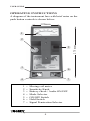
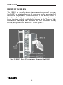
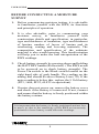
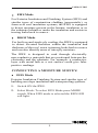
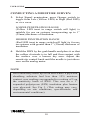
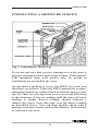
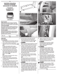
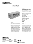
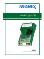
user guide
RWS
08/2013
roof and wall scanner
USER GUIDE
TABLE OF CONTENTS
Introduction...............................................................2
Operating instructions...............................................4
Modes of operation.....................................................5
How it works .............................................................6
Principles of operation...............................................7
Prior to use.................................................................7
Before conducting a moisture survey........................8
Conducting a moisture survey: EIFS mode...............9
Interpretation of readings.........................................12
Conducting a moisture survey: Roof mode.............16
Procedure ................................................................17
Tracing a leak..........................................................19
Types of roofing structures......................................21
Possible problems leading to moisture intrusion.....21
Moisture survey checklist ......................................22
Useful items when conducting a survey...................22
Correct use of RWS..................................................23
Maintenance of RWS...............................................24
Limitation & calibration..........................................25
Warranty...................................................................26
Warranty claims.......................................................27
Product development...............................................27
Safety.......................................................................27
1
USER GUIDE
INTRODUCTION
To get maximum benefit from your Tramex RWS - Roof
and Wall Scanner, it is suggested that before undertaking a
moisture survey, you read this manual to familiarize
yourself with the operation, features and capabilities of
this multi-mode non-destructive moisture detection and
scanning instrument.
TRAMEX RWS AND THE BUILDING
ENVELOPE
The building envelope is the physical separator between the
interior of a building and the external environment in which it
is located. It consists of the roof, walls and floor of a structure.
It should be noted that the entire roof (external covering or
protective layer to finish on ceiling), walls (external finish to
internal finish), floor (sub-floor to floor finish) and windows
are considered to be part of the building envelope. These are the
elements that form the boundary between the interior of the
building and the external environment. The building envelope
can be considered as a filter between the internal and external
environments. The design of the building envelope greatly
influences the energy performance of a building. Moisture in
elements of the building envelope can significantly affect the
performance of the building envelope and have other serious
consequences such as damage to materials and deterioration of
air quality. Tramex manufacture a complete range of
instruments for the detection and measurement of moisture in
the building envelope. For roofing, walls and many types of
floor construction the Tramex Roof and Wall Scanner (RWS)
is the complete instrument. As originally developed the
RWS is a hand-held, non-destructive, electronic moisture
meter specifically for non-destructive moisture evaluation
and surveying of built-up or single-ply roofing and EIFS
(Exterior Insulation and Finishing System).
2
USER GUIDE
However its use by many professionals over the years has
demonstrated that it goes far beyond these applications
and extends to all aspects of the building envelope.
The Tramex RWS is an effective Leak Seeker and
Moisture Scanner with 2 operating modes, with each
mode having 2 ranges of sensitivity. This affords the user
the opportunity to scan roofing, walls and the building
envelope for excess moisture. The less sensitive yellow
mode is designated for built-up and single-ply roofing
with the more sensitive red mode for EIFS and foam
installation. With the large variety of constructions that
exist these designations are not always rigid and can vary
significantly e.g. the more sensitive mode can be used on
foamed-over roofing systems.
For those familiar with Tramex moisture meters, the RWS
incorporates two of the well-known moisture scanners
from Tramex, with additional features and benefits, in one
instrument. These are the Leak Seeker, launched in 1983,
for the tracing of leaks and detection of moisture in
roofing systems and the Wet Wall Detector (WWD),
launched in 1995, for the detection of moisture in EIFS.
3
USER GUIDE
OPERATING INSTRUCTIONS
A diagram of the instrument face with brief notes on the
push button controls is shown below:
120mm
1
5
3
6
7
4
1
2
3
4
5
6
7
=
=
=
=
=
=
=
Moving coil meter.
Sensitivity Knob
Battery check / Audio ON/OFF
Mode Selector
ON/OFF Switch
Hold Switch
Signal Penetration Selector
4
275 mm
2
USER GUIDE
MODES OF OPERATION
The RWS (Roof and Wall Moisture Scanner) has two
operating modes, each with two ranges of signal penetration.
The mode and signal penetration are indicated by the
white and orange boxes on the decal of the RWS
instrument.
EIFS Mode (Red LED selected on White switch.) is
for moisture scanning of Exterior Insulation and
Finishing System (EIFS) and similar type of construction
cladding as well as polyurethane and polystyrene
foam insulation and other types of low-density
insulation systems applied to the building envelope.
Roof Mode (Yellow LED selected on White switch) is
for moisture scanning and leak tracing of built-up and
single ply roofing systems.
Each of these measurement modes incorporates two
sensitivities, which are activated by pressing the Orange
switch: Yellow LED for lower sensitivity and lower
penetration. Red LED for higher sensitivity and deeper
penetration.
Audio can be turned ON/OFF by pressing Audio twice in
quick succession.
5
USER GUIDE
HOW IT WORKS
The RWS is an electronic instrument powered by one
9volt PP3 or similar battery. It operates on the principal of
electrical impedance measurement. This means that a
harmless, low frequency, non-destructive signal is sent
from the two rubber coated electrodes at the base of the
instrument through the surface of the material being
tested, deep into this material. See Figure 2.
Fig. 2. RWS Low Frequency Signals On EIFS
6
USER GUIDE
PRINCIPLES OF OPERATION
To measure / detect moisture, the rubber coated base of
the instrument is pressed onto the material being tested.
The detection signals from the instrument penetrate the
material under test to a depth of up to approximately 75
mm. (3 inches) depending on the mode, the range of
sensitivity selected and the material being tested.The
small current flowing through the field is inversely
proportional to the impedance of the material. This
current is a measure of the change in the electrical
impedance caused by a change in the moisture content.
This change is translated by the RWS and instantly and
continuously displayed on the large clear analog dial
which gives comparative readings of 0 to 100.
PRIOR TO USE
Although the RWS is checked on manufacture and at
quality control to ensure it is in working order before
leaving the factory, a few minor checks should be carried
out following transit. These are as follows :
Depress ON/OFF switch (located on fascia to the right of
grab handle) to power on the RWS. Check battery strength
by depressing BATTERY check switch. The needle on the
analog dial should go past the BATTERY line on the dial.
If not, change the battery. Set the sensitivity dial to 10,
place your hand on the base of the instrument, making
contact with both electrodes, a full-scale reading of 100
should be obtained, irrespective of which mode or range
is selected. See Page 4 for graphic illustration of switches
and controls.
Ensure that your new RWS is received in pristine condition,
just as it left our factory. Complete and return warranty
registration card to Tramex or the supplier of your RWS.
7
USER GUIDE
BEFORE CONDUCTING A MOISTURE
SURVEY
1.
Before commencing moisture testing, it is advisable
to familiarise yourself with the RWS, its functions
and principles of operation.
2.
It is also advisable, prior to commencing your
moisture survey, to familiarise yourself with
construction details and specification, in particular,
type and thickness of insulation, type and thickness
of lamina, number of layers of lamina and its
reinforcing, coating and covering materials. The
composition and specification of the substrate
material is also worth knowing. This familiarisation
will help you to make the best interpretation of the
RWS readings.
3.
Check battery strength by pressing down and holding
the BATTERY button (Red switch). (The RWS needs
to be powered on to check battery strength). The
Power On switch is the Black switch located on the
right hand side of grab handle. The reading on the
analog dial should be above Battery Line (70). If the
meter reading is below this, replace the 9 Volt battery
(PP3, 1604, 6F22, 6LF22 or equivalent).
4. If meter does not power up, remove the battery cover
and check if the battery is connected. If not, connect
and ensure that the battery is firmly positioned within
the battery retainer.
It is important that the battery is firmly positioned and not free
to move, as due to the sensitivity of the RWS an incorrectly
positioned or loose battery could affect the readings.
8
USER GUIDE
EIFS Mode
For Exterior Insulation and Finishing System (EIFS) and
similar types of construction cladding (non-metalic), or
foam-over roof insulation systems, the RWS is equipped
to detect moisture present in the lamina, insulation or in
the substrate behind or under the insulation and assists in
tracing leaks back to source..
ROOF Mode
For built up and single ply roofing, the RWS is equipped
to detect elevated moisture within the insulation and
thickness of the roof, assist in tracing leaks back to source
and can also identify areas of inter-ply moisture.
The RWS is designed to read through electrically
non-conductive materials that are positioned between the
electrodes and the substrate. For example: a conductive
layer with metal lath or a wet surface could give false
positive readings.
CONDUCTING A MOISTURE SURVEY:
EIFS Mode
Exterior Insulation Finishing System and similar type of
building envelope insulation and waterproofing systems.
1.
Switch ON the RWS.
2.
Select Mode: To select EIFS Mode press MODE
switch. When EIFS mode is selected the RED LED
will light.
9
USER GUIDE
CONDUCTING A MOISTURE SURVEY:
3. Select Signal penetration: press Orange switch to
toggle from Low (Yellow LED) to High (Red LED)
or vice versa.
LOWER PENETRATION RANGE
(Yellow LED inset in range switch will light) is
suitable for use on systems incorporating up to 1”
(25mm) thickness of insulation.
HIGHER PENETRATION RANGE
(Red LED inset in range switch will light) is for use
on systems with greater than 1” (25mm) thickness of
insulation.
4. Hold the RWS by the grab handle and place it so that
the rubber electrode is in full and firm contact with
the surface over a known dry area. Adjust the
sensitivity control knob until the needle is just above
zero on the analog meter.
NOTE
On a laboratory mock up on an area where a plywood
sheathing substrate had less than 15% moisture
content, zero reading corresponded to a setting of 5 on
the sensitivity knob of RWS. This was on a 1”
expanded polystyrene (EPS) insulation plus lamina
over plywood. See Fig 3. (This setting may vary,
depending on site conditions, specifications and
environmental conditions).
10
USER GUIDE
CONDUCTING A MOISTURE SURVEY:
Fig 3. Laboratory Mock-Up
Fig 3. Laboratory Mock-Up
If you are not sure that you are starting over a dry area, a
pin-type resistance meter such as the Tramex Professional,
with insulated deep wall probes may be useful in
confirming an acceptably dry area.
An alternative method is to use the RWS on a seek and
find basis as follows: Place the RWS against the surface,
adjust the sensitivity control knob so that the meter reads,
say 50. Then, by moving from area to area and following
in the direction of lowest reading until the area of lowest
reading is found (lowest reading should indicate a
relative dry area). Over this area, zero the meter reading
as described above. You can then double check with a
pin-type resistance meter such as the Tramex Professional
to confirm a dry area.
11
USER GUIDE
CONDUCTING A MOISTURE SURVEY:
Having calibrated (zeroed) on a dry area, now proceed
with the moisture survey by moving the RWS across the
surface, making sure that electrodes are making full and
firm contact with the surface. Partial contact may result in
reduced readings. Also ensure that you are holding the
RWS firmly by its grab handle as the RWS functions more
efficiently when it is hand held while in EIFS mode. If you
are setting up a grid pattern for your survey it is important
to understand that the RWS is reading the area directly
below the footprint of the instrument.
INTERPRETATION OF READINGS
When the RWS has been zeroed correctly on a dry area and
set on the correct range for the EIFS thickness, higher
readings normally indicate higher moisture content.
Example:
The RWS was calibrated on a laboratory mock-up shown
in Table 1. ( page 13 )
Structural Wood:
4” x 2” Stud
Sheathing:
1/2” Plywood
Insulation:
1”Expanded polystyrene
Lamina:
Glass Fibre Reinforced
12
USER GUIDE
INTERPRETATION OF READINGS
Calibration was set on this as follows:
Table 1. Comparison of RWS and Professional Pin
Type Resistance Meter Readings
It should be noted that calibration of the RWS in EIFS
MODE was based on the averaged results of numerous
on-site and laboratory tests. Therefore readings and
results vary depending on construction detail and from site
to site. The above chart was the result of tests conducted
on a simulated wall construction, as described above and
is for guidance purposes only. Readings from the RWS are
qualitative, not quantitative, and should be used for
comparative purposes only.
13
USER GUIDE
INTERPRETATION OF READINGS
As EIFS systems, construction sites, environmental and
geographical conditions vary, results and readings will
vary also. It is recommended that when carrying out a
survey the RWS is zeroed on individual walls and
anywhere the operator would expect a change in wall
materials, lamina, surface moisture or other conditions
that may effect readings.
For example, walls or roofs on ocean-side properties may
have higher salt content on the surface and thus slightly
higher readings than inland properties, or surface
moisture may dry off more slowly depending on
orientation of the wall or roofs.
The RWS is designed to have the flexibility in sensitivity
adjustment to cope with variances caused by material and
conditional differences from wall to wall.
TRACING MOISTURE BACK TO SOURCE IN
EIFS OR SIMILAR CONSTRUCTION
Once an area of excess moisture has been established, the
RWS may be used to assist in tracing the moisture to the
source of ingress as follows:
Having found a wet area, turn down the SENSITIVITY
knob until the needle points to approximately half scale
(approx 50).
On this setting, take further readings around the area, note
the highest reading and follow in the direction of the
highest reading. If necessary, decrease sensitivity until the
area of greatest moisture has been located.
14
USER GUIDE
TRACING MOISTURE BACK TO SOURCE IN
EIFS OR SIMILAR CONSTRUCTION
Usually the greatest moisture concentration is in the
proximity of the area where the moisture is getting into the
system. A careful visual examination in this area should be
carried out to identify defects or damage in
weatherproofing.
Taking core samples of the EIFS or foamed roof insulation
and / or the use of a pin type resistance meter such as a
TRAMEX PTM with deep wall probes is recommended to
substantiate the RWS readings.
Fig. 4. Professional Pin Meter With Deep Wall Probe.
15
USER GUIDE
CONDUCTING A MOISTURE SURVEY:
ROOF Mode
For moisture scanning and leak tracing of Built-Up and
Single-Ply Roofing Systems.
Conducting A Roof Survey
1. Switch the RWS ON
2. Select Mode: To select Roof Mode press White
MODE switch. When Roof mode is selected the
Yellow LED will light.
3. Select Signal penetration: press Orange switch to
toggle from Low Range (Yellow LED) to High Range
(Red LED) or visa versa.
LOWER PENETRATION RANGE
(Yellow LED inset in Orange switch will light) is
suitable for use on smooth or mineral surfaced roofs.
HIGHER PENETRATION RANGE
(Red LED inset in Orange switch will light) is more
sensitive and will read through heavier membranes as
well as most dry gravel or ballast roof coverings. (If
satisfactory readings cannot be achieved through
ballast, remove same and work directly on the surface
of the waterproofing material).
16
USER GUIDE
CONDUCTING A MOISTURE SURVEY:
Procedure
1. Make a sketch of the roof, indicating openings and
protrusions etc.
2. Select a convenient grid span e.g. 6ft (2m). On the
North/South perimeter, mark 1,2,3 etc and on the
East/West perimeter mark A, B, C etc. Transfer these
grid system markings to your roof sketch. See Fig. 5.
Proceed by moving the RWS along the imaginary line
3. A and mark locations on the sketch graph paper and /
or roof surface when moisture is indicated by the
RWS.
Fig. 5. Roof Grid Sketch
17
USER GUIDE
CONDUCTING A MOISTURE SURVEY:
In Fig.5 position A4 is the first point of moisture
contact. A telescopic aluminium handle can be
attached to the RWS when carrying out a moisture
survey on a horizontal surface to avoid having to bend
down when taking readings. As the survey continues,
a moisture profile will build up, indicating areas
which require attention.
4. On single ply roofing, particular attention must be
paid to laps and seams.
5. Should a precise moisture percentage be required, a
sample can be removed from the site, sealed in a
plastic bag and checked in a laboratory, by weighing,
drying and re-weighing, to calculate the exact amount
of moisture present.
6. It is important also to examine the plies of the
waterproofing layers after taking a test cut, as moisture
may be present between the plies or within the fibre of
the felt.
7. Areas of elevated moisture can be checked with a
probe type moisture meter such as the Tramex
Professional pin-type meter with deep wall insulated
probes.
18
USER GUIDE
TRACING A LEAK AND CHECKING
SUSPECTED TROUBLE AREAS
If, for instance, a leak has been noticed in a built-up-roof,
it may be easy to identify where the water is dripping into
the building, but difficult to locate the point of ingress in
the waterproof layer. Take your RWS to the general area of
the roof over the leak. Switch on to activate the RWS and
select the desired range. Turn the sensitivity knob to 10
and place the RWS on the roof surface. (If no reading is
received, the insulation directly beneath the instrument is
dry). Take point readings around the area until moisture is
located.
This identifies where the elevated moisture is located.
Mark the roof surface with crayon or paint, outlining the
area of wetness. See Fig 6. below.
Fig 6. Tracing And Marking A Leak On Your Roof
19
USER GUIDE
TRACING A LEAK AND CHECKING
SUSPECTED TROUBLE AREAS
To trace the leak back to the source, turn down the
sensitivity until the meter needle reads approximately half
scale. Take point readings around the area of the leak,
following the strongest signal. It may be necessary to
reduce the sensitivity a number of times until the area of
greatest moisture content is located. Based on the usual
pattern of greatest moisture concentration being in
proximity to the point at which the moisture gets through
into the roof, a visual examination of the area should be
carried out to identify defects or damage to the roof
covering.
Note: The reading on the RWS. is 'Relative' or
'Comparative', indicating a greater or lesser signal. It is not
an indicator of percentage moisture content. As a guide,
approximately 20% moisture in wood fibreboard directly
under a 3mm (1/8”) membrane, will give full-scale
deflection in Roof Mode on the Yellow sensitivity range.
Many types of insulation currently available can contain
up to 200% moisture by weight while others can hold very
little mositure. If the precise moisture content is required
we recommend a sample core is cut and measured by
weigh/dry/weigh method, or by use of a pin type resistance moisture meter. The Tramex Professional pin-type
meter can be used to give a better indication of moisture
content.
20
USER GUIDE
TYPES OF ROOFING STRUCTURES AND
THEIR MORE COMMON PROBLEMS
Built-up Roofing Systems: Comprising of 3 or 4
layers of roofing felt, with bitumen or asphalt
adhesive between each layer.
Modified Bitumen Systems: This type of material is
usually heat applied as a single layer system or with a
base layer of bituminous felt.
Single Ply Roofing: Usually applied in welded sheet
form, direct to the insulation.
Note: Using the RWS on black EPDM or Butyl
rubber roofing may result in false readings due to the
high dielectric constant of this material.
POSSIBLE PROBLEMS LEADING TO
MOISTURE INTRUSION OF THE ROOF
SYSTEM
Mechanical damage from maintenance personnel.
Fissures or cracks in the membrane, caused by
building settlement or expansion and contraction.
Blistering caused by moisture trapped in the roofing
system during construction.
Problems on the laps and up stands if material is not
fully sealed during construction.
Problems usually occur from mechanical damage and
maintenance personnel, pinholes, bird damage and
faulty seams during construction.
21
USER GUIDE
MOISTURE SURVEY CHECKLIST
Recording the following information will assist you in
completing a comprehensive moisture survey:
1. Building name and number.
2. Date of survey.
3. Name of surveyor.
4. Visual inspection of all detail work and
flashings around doors, windows, openings etc
5. Visual inspection of windows, doors,
penetrations, roof lights & openings etc.
6. Visual inspection of vents, chimneys and other
protrusions.
USEFUL ITEMS REQUIRED WHEN
CONDUCTING A SURVEY
1. Core cutter.
2. Hole punch.
3. Crayon, chalk or spray paint.
4. Tape measure.
5. Spatula, knife and cold mastic, and patching
material for minor repairs.
6. Plastic bags for sealing core samples.
7. Pin-type resistance meter with deep wall insulated
probes.
22
USER GUIDE
CORRECT USE OF RWS
Make sure that the RWS is held firmly by its built-in
plastic grab handle and that your hand is not in
contact with the electrode or sides of the instrument.
Extension handles, such as telescopic handles, should
not be used while in EIFS Mode, as these will affect
reading and performance of the RWS, and the handle
should not be insulated or isolated from operator’s
hand when in use. The telescopic extension handle
should only be fitted to the RWS for use on roofing in
Roof Mode.
All of the rubber electrodes need to be placed in firm
contact with the surface. On narrow areas where full
electrode contact is lacking or not possible, it may be
necessary to recalibrate the meter.
On areas where thickness of insulation or lamina
varies from that at where the RWS was zeroed,
readings may be affected. It may be necessary to
compensate for these differences in coatings or
insulation specifications.
At temperatures below 32°F (0°C) the RWS may not
function efficiently due to the presence of moisture
turning to ice.
Readings at lower temperatures tend to be lower than
those at higher temperatures.
23
USER GUIDE
MAINTENANCE OF RWS
Keep the electrodes clean and dry and regularly
inspect for wear.
Clean electrodes with a damp cloth. Do not use
solvents to clean the RWS.
Remove battery when the RWS is stored for long
periods.
The replacement battery should be of good quality
and leak proof.
The RWS will automatically power off after 30
minutes of inactivity. Avoid leaving the RWS
switched on while not in use.
In the event of a malfunction, return to your supplier.
The RWS carries a 12-month warranty. Details and
warranty card are supplied with the instrument.
24
USER GUIDE
Limitations
The RWS will not detect or measure moisture through any
electrically conductive materials including metal sheeting
or cladding, black EPDM
roofing, butyl roofing,
aluminum siding or wet surfaces.
Calibration
Should it be found that readings are outside the set
tolerances, it is recommended that the RWS be returned
for re-calibration. Calibration adjustments should not be
carried out by anyone other than Tramex or their
authorised service provider who will issue a calibration
certificate on completion. Requirements for quality
management and validation procedures, such as ISO 9001,
have increased the need for regulation and verification of
measuring and test instruments. It is therefore
recommended that calibration of the RWS should be
checked and certified in accordance with the standards
and/or protocols laid down by your industry (usually on
an annual basis) by an authorized test provider. The name
of your nearest test provider and estimate of cost is
available on request.
25
USER GUIDE
Warranty
Tramex warrants that this instrument will be free from
defects and faulty workmanship for a period of one year
from date of first purchase. If a fault develops during the
warranty period, Tramex will, at its absolute discretion,
either repair the defective product without charge for the
parts and labour, or will provide a replacement in
exchange for the defective product returned to Tramex
Ltd. This warranty shall not apply to any defect, failure or
damage caused by improper use or
improper or
inadequate maintenance and care.
In no event shall Tramex, its agents or distributors be
liable to the customer or any other person, company or
organisation for any special, indirect, or consequential
loss or damage of any type whatsoever (including, without
limitation, loss of business, revenue, profits, data, savings
or goodwill), whether occasioned by the act, breach,
omission, default, or negligence of Tramex Ltd., whether
or not foreseeable, arising howsoever out of or in connection with the sale of this product including arising out of
breach of contract, tort, misrepresentation or arising from
statute or indemnity. Without prejudice to the above, all
other warranties, representations and conditions whether
made orally or implied by circumstances, custom,
contract, equity, statute or common law are hereby
excluded, including all terms implied by Section 13, 14
and 15 of the Sale of Goods Act 1893.
26
USER GUIDE
Warranty claims
A defective product should be returned shipping pre-paid,
with full description of defect to your supplier or to
Tramex at address shown on the back of this guide.
Product development
It is the policy of Tramex to continually improve and
update all its products. We therefore reserve the right to
alter the specification or design of this instrument without
prior notice.
Safety
This user guide does not purport to address the safety
concerns, if any, associated with this instrument or its use.
It is the responsibility of the user of this instrument to
establish appropriate safety and health practices and
determine the applicability of regulatory limitations prior
to use.
27
www.tramexltd.com
Tramex Ltd.
Shankill Business Center, Shankill, Co. Dublin, Ireland.
Tel: +353 1 239 3224, Fax: +353 1 282 7880
Email: [email protected]
USA and Canada Tramex c/o Black Hawk Sales Inc.
4901 Fox Ridge Court, Fort Collins, CO 80524
Tel: 970 488 1898, Fax: 877 525 9279
Email: [email protected]