1
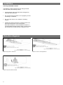
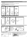
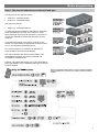
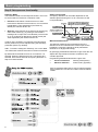
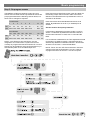
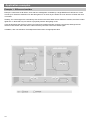
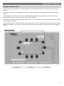
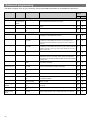
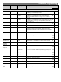
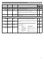
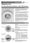
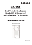
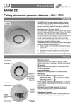
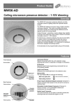
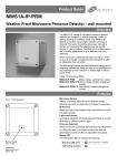
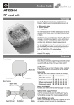
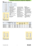
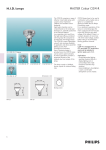
Product Guide MWS3A-AT-DD RF ceiling microwave presence detector – DALI / DSI Overview The MWS3A-AT-DD is a passive microwave motion sensor combined with two output channels capable of controlling incandescent, fluorescent and compact fluorescent lighting. The MWS3A-AT-AD detects movement using a highly sensitive microwave detector. This works by emitting low power microwave signals and measuring the reflections as the signals bounce off moving objects. Output Channel 1 comprises a mains voltage relay capable of simple on/off switching, while Output Channel 2 provides dimmable control of either DSI or DALI type ballasts. Functioning as a presence detector, the unit can turn lights on when a room is occupied and off when the room is empty. Optional settings allow lights to be turned off in response to ambient daylight, or to implement a maintained illuminance (constant light) system. The unit also includes stored scenes for versatile manual control of lighting levels. The MWS3A-AT-DD can be used as a standalone unit or integrated with other devices as part of a system. The built-in RF transceiver allows wireless communication with all other An-10® compatible products, e.g. the AT-BB-IN Input Unit, useful for push-button scene selection and absence detection. All functionality is fully programmable. Features Microwave Sensor Detects movement within the unit’s detection range, allowing load control in response to changes in occupancy. Front features Mounting Bezel IR Receiver Receives control and programming commands from an IR (infrared) handset. Sensor Lens which covers... Microwave Sensor IR Receiver Light Level Sensor Status LEDs Back features Light Level Sensor Monitors the ambient light level, allowing load control based on minimum and maximum Lux Level and also for providing Maintained Illuminance (constant light) control. Status LEDs These flash Red and/or Green to indicate the following: Walk Test LED active when movement is detected Valid setting received Invalid setting received Software reset received Factory reset received Power Input & Switched Output Connector (Channel 1) Used to connect mains power to the unit and to connect a switched load. Dimmable Control Output Connector (Channel 2) Used to connect DSI/DALI controllable ballasts and transformers for dimmable loads. Installation Choosing a Suitable Location The MWS3A-AT-DD is designed to be ceiling mounted and must satisfy the following criteria: Avoid positioning the unit where direct sunlight may enter the sensor element. Do not site the sensor within 1m of any lighting, forced air heating or ventilation. Do not fix the sensor to an unstable or vibrating surface. Position the sensor so that the occupants of the room fall inside the detection zone shown below. Note that the detection zone illustrated is based on a recommended mounting height of 2.8m. A lower height will decrease the overall size of the detection zone. Detection diagrams Ideal for large office or classroom Ideal for open plan areas and offices 2 Ideal for corridor or aisle applications Installation The MWS3A-PRM is designed to be mounted using either: Flush fixing, or Surface fixing, using the optional Surface Mounting Box (part no. MWS3A-DBB). Both methods are illustrated below. Warning - be careful bending springs when mounting unit. Surface fixing 1 2 3 Hole Ø74mm 4 Attach cable clamp Flush fixing 1 2 3 4 Hole Ø30mm MAX Head locking 1 Remove metal locking clip from rear of unit. 2 Adjust head to required position. Push clip into position shown below to lock head. To remove clip, lever out with a small screwdriver. Wire stripping details Important Ensure that the cables are formed as shown before affixing the cable clamp. The clamp MUST clamp the outer sheath(s) only. Bend cores as shown. 3 Wiring examples Channel 1 (switched output) of the MWS3A-AT-DD can either be used to switch a separate channel of standard, non-dimming luminaires, or to isolate the mains supply to dimming ballasts (saving on the standby current of the ballasts). Multiple luminaires may be connected in parallel to Channel 1 (via the N and L/Out terminals) as long as the maximum total load is not exceeded. be used to control the light output of luminaires that are fitted with dimming ballasts/transformers. The ballasts/transformers can be connected in parallel to Channel 2 (via the DIM– and DIM+ terminals). Ensure that correct polarity is maintained at each ballast. Refer to the specification on page 16 for ballast quantities. The wiring examples below show common methods of connecting the output channels for a single detector unit. Channel 2 (dimmable output) of the MWS3A-AT-DD can Example 1: Single channel switching Functionality Simple On/Off load control. Presence detection. Absence detection using an ATBB-IN Input Unit and associated switch/button plate. Manual On/Off control using IR Handset. Lux switching. Example 2: Single channel dimming Functionality Dimmable load control via suitable ballast/transformer. Mains power to ballast switched by channel 1. Presence or absence detection (with or without Lux Level control). Manual scene/level control using IR Handset or AT-BB-IN Input Unit and associated switch/button plate. Optional Maintained Illuminance Level control. Example 3: Two channel Please note that the dimming signal is used to switch the dimming luminaire on/off and therefore the 230V feed to the luminaire fitting must come from the permanent live supply 4 Functionality Separate control of both a simple On/Off load and dimmable load (control via suitable ballast/ transformer with integral mains switching). Presence / absence detection (with or without Lux Level control). Manual scene/level control using IR Handset or AT-BB-IN Input Unit and associated switch/button plate. Optional Maintained Illuminance Level control. Power-up test procedure When power is applied to the unit, the load will turn on immediately. Vacate the room or remain very still and wait for the load to switch off (this should take around 10 minutes). Check that the load switches on when movement is detected. The unit is now ready for programming. Fault finding What if the load does not turn ON? Check that the live supply to the circuit is good. Check that the load is functioning by bypassing the sensor (e.g. link terminals L and L/ Out on Channel1). Check that the unit is correctly addressed, see ‘Step 1: Set channel addresses and channel load type’ on page 7. If the detection range is smaller than expected, check the diagrams in page 2. Rotating the sensor slightly may improve the detection range. HINT: The Walk Test LED function can be used to check that the unit is detecting movement in the required area (see page 8 for further details). What if the load does not turn OFF? Ensure that the area is left unoccupied for longer than the Time Adjustment Period (default is 10 minutes). Ensure that the sensor is not adjacent to circulating air, heaters or lamps. HINT: The Walk Test LED function can be used to check that the unit is detecting movement in the required area (see page 8 for further details). 5 Basic programming The functionality of the MWS3A-AT-DD Sensor is controlled by a number of parameters which can be changed or programmed by any of the following devices: For most basic programming operations the UHS4 handset is recommended and the following procedures are based on using this device. Point the handset at the Sensor and send the required programming commands to the unit as shown in Steps 1, 2 and 3. UHS4 Infrared Handset UNLCDHS Infrared Handset (with LCD) Valid commands will be indicated by a green LED flash. See page 1 for details of other LED responses. Important note Do not use as hub if the installation uses Area Codes. If Area Codes are used, make a non MWS3A-AT detector or Slim-line controller a hub in the same local codes as the MWS3A-AT . 6 Basic programming Step 1: Set channel addresses and channel load type The Sensor has two output channels: Channel 1 - Switched Output Channel 2 - Dimmable Output and one input channel: Channel 3 - Microwave Sensor To relate the function of different channels it is necessary to set the addresses correctly. For example, a scene select message sent from a device with a Local Code of 1 will only be actioned by devices that also have a Local Code of 1. To program the settings for a specific channel on the Sensor you must specify the appropriate channel number (i.e.1 to 3) using the programming device. If no channel number (or channel 0) is specified, all channels will be set to the same address. The output channels also have Circuit numbers. This allows different physical channels to be linked and controlled as a single Circuit. Channel 2 (the dimmable output) can control either DSI or DALI type ballasts. This is called the Load Type and is set to DSI by default. Note: for applications where there is only one channel of lighting being controlled in a room there is no need to select the channel number. 7 Basic programming Step 2: Set-up sensor functionality Detection Mode The Detection Mode for both output Channels 1 and 2 can be set to behave in Presence or Absence mode: Switch Level On/Off Occupancy detection can be made dependant on the ambient light level using the Lux On Level and Lux Off Level parameters. Presence mode allows a channel to turn on when movement is detected. Once turned on, if no movement is detected the Time Adjustment (10 minutes by default) the channel will turn off. Absence mode requires the channel to be turned on by some other means (e.g. by issuing a Scene Select message via an Input Unit or IR Handset). Once turned on, if no movement is detected for period of time (the Time Adjustment) the channel will turn off. In either case, sensitivity to movement of the Microwave sensor (Channel 3) can be adjusted using the Sensitivity parameter (set to 5 by default). HINT: To assist in setting the Sensitivity, turn on the Walk Test LED which will flash red when movement is detected. By default when the detector turns on Local Scene 1 is selected. When the detector turns off Local Scene 20 is selected. See ‘Scenes Used for Occupancy Detection’ in Step 3 for further details. Maintained Illuminance The detector measures the overall light level in the detection area and calculates the correct output for the luminaires, to achieve a preset lux level (maintained illuminance or daylight harvesting). By specifying a Maintained Illuminance Light Level the unit adjusts the output Channel levels to maintain a near constant light level. Programming Maintained Illuminance Light Level Presence detection Sensing mode (below) Absence detection Scene mode (opposite) Note: for applications where there is only one channel of lighting being controlled in a room there is no need to select the channel number. 8 Basic programming Step 3: Re-program scenes The MWS3A-AT-DD has capacity to store 20 Local Scenes and 120 Area Scenes. By default all Scenes are pre-programmed with the following channel levels, but these can be changed as required: Local Scenes 1 Ch1 on 2 3 4 5 6 ... 19 20 on on on on on ... on off Ch2 100% 75% 50% 25% 100% 75% ... Ch1 on on on on on on Ch2 100% 75% 50% 25% 100% 75% ... ... Each Scene also has a Maintained Illuminance Level setting. By default this is set to 0 (i.e. disabled) for all Scenes. 50% 0% Scenes Used for Occupancy Detection 119 220 If movement is detected (in Presence mode), Local On Scene 1 is selected. By default this switches Channel 1 On and sets Channel 2 to 100% with a 1 second Fade Rate. Area Scenes 101 102 103 104 105 106 ... Each Scene has a Fade Rate, which is the time taken for the existing output channel levels to fade to the levels defined in the selected Scene. By default this is set to 3 seconds for all Scenes. on off 50% 0% NOTE: Local Scene 20 and Area Scene 120 are designated ‘off’ scenes within a system and should normally be programmed with all channels off or at zero. Scenes can be recalled by using an IR Handset or by a switch/button plate via an AT-BB-IN Input Unit. If no movement is detected for the Time Adjustment Period (in Presence or Absence mode), Local Off Scene 20 is selected. By default this switches Channel 1 Off and sets Channel 2 to 0% with a 1 second Fade Rate. NOTE: These ‘On’ and ‘Off’ Scene selections cannot be changed using the UHS4 handset. You can, however, reprogram the levels for Scenes 1 and 20 if required. 9 Application examples Example 1: Offices and corridor Example 1 shows two small offices, each with four downlighters controlled by a single MWS3A-AT-DD sensor. These are set-up for Presence detection such that the lights turn on when anyone enters the room and turn off when the room is vacated. Similarly, the corridor lights are controlled by two sensors such that if either sensor detects movement, all of the corridor lights turn on. Note that only one sensor is physically wired to the lighting circuit. In this arrangement the devices in each room need to be programmed with a unique Local Code, although the two devices in the corridor share the same code so that they can both control the corridor lights. In addition, each unit needs its Time Adjustment Period set to an appropriate value. 10 Application examples Example 2: Meeting room Example 2 shows an application for a typical meeting room. An MWS3A-AT-DD sensor is used, set-up for Absence detection. The sensor controls the six downlighters via Channel 1 (switched output) and two wall lights via Channel 2 (dimmed output). Fully independent control of both circuits can be provided with suitable scene programming. Scene selection and manual control of all circuit levels can be achieved via an IR Handset. In addition, this example shows two AT-BB-IN input units used in conjunction with wall mounted button plates to provide manual selection of scenes. Since the detectors are in Absence detection mode, lights will only turn on in response to manual operation of the button plates or IR Handset. If no movement is detected for the specified Time Adjustment Period, the lights will automatically turn off. 11 Advanced programming The tables on pages 12 to 15 give a summary of all programmable parameters for the MWS3A-AT-DD Sensor. Parameter Name Default Value Range / Options Description Programming Devices UHS4 UNLCDHS For Device Product ID Automatically assigned by the device 1 to 999 A number used to uniquely identify each device within a range of devices that are set to the same Local Code. Building Code 1 1 to 999 A number shared by all devices that belong to the same building or system. Lock 0 Enable (1) or disable (0) Lock the An-10 network. Prevents more devices joining the network. 1 to 999 A number corresponding to the Local Code of all devices to be controlled by an associated input channel. Sub Local Code(s) Not set 1 to 99 0 to clear A number corresponding to the Sub Local Code of all devices to be controlled by an associated input channel. Up to 20 Sub Local Codes can be set for Channel 1 and 2, e.g. 15 on Ch.1 and 5 on Ch.2, etc. Area Code(s) 999 1 to 999 0 to clear A number corresponding to the Area Code of all devices to be controlled by an associated input channel. Up to 32 Area Codes can be set for Channel 1 and 2, e.g. up to 16 per channel, or 20 on Ch.1 and 12 on Ch.2, etc. Circuit Number 1 1 to 999 Sets the circuit number for this channel. Detection Mode Presence Presence or Absence Presence mode allows the output to turn on when movement is detected and off when movement ceases. Absence mode allows the output to turn off when movement ceases, but must be manually turned on first. Output State Set by Scene 0-100% 0=off The current output state of the channel, for example as set by a Scene Select command. Light Level Set by Scene 0 (disabled) or 1 to 999 The maintained illuminance target level of the channel, for example as set by a Scene Select command. See page 8. Raise from off 1 Enable (1) or disable (0) Enables raise from off feature. Lower from off 1 Enable (1) or disable (0) Enables lower from off feature. Emergency output 0 Enable (1) or disable (0) Enabling this sets the output to a ‘switched permanent live’ mode for emergency ballasts. Lux off period 0 0 to 999 in minutes (0=15 seconds) Number of minutes above the Lux Off level before a lux switching decision is made. Lux switching enabled 1 Enable (1) or disable (0) Enables or disables the output channel to respond to lux switching commands. Detector enabled 1 Enable (1) or disable (0) Enables the output channel to be controlled by detector occupancy. Detector inhibit period 0 0 to 255 Detector inhibit period in 100s of milliseconds (255 = 25 seconds). For Channel 1 (Switched Output) Local Code 1 (maintained illuminance) 12 Advanced programming Parameter Name Default Value Range / Options Description Programming Devices UHS4 UNLCDHS For Channel 2 (Dimmed Output) 1 to 999 A number corresponding to the Local Code of all devices to be controlled by an associated input channel. Sub Local Code(s) Not set 1 to 99 0 to clear A number corresponding to the Sub Local Code of all devices to be controlled by an associated input channel. Up to 20 Sub Local Codes can be set for Channel 1 and 2, e.g. 15 on Ch.1 and 5 on Ch.2, etc. Area Code(s) 999 1 to 999 0 to clear A number corresponding to the Area Code of all devices to be controlled by an associated input channel. Up to 32 Area Codes can be set for Channel 1 and 2, e.g. up to 16 per channel, or 20 on Ch.1 and 12 on Ch.2, etc. Circuit Number 2 1 to 999 Sets the circuit number for this channel. Load Type DALI DSI or DALI Sets the ballast control protocol to be used by the output channel. Detection Mode Presence Presence or Absence Presence mode allows the output to turn on when movement is detected and off when movement ceases. Absence mode allows the output to turn off when movement ceases, but must be manually turned on first. Output Level Set by Scene 0 to 100 % The current output level of the channel, for example as set by a Scene Select command. Max Value 100% 0 to 100% Maximum dimming output level. Min Value 0% 0 to 100% Minimum dimming output level. Maintained Illuminance Level Set by Scene 0 (disabled) or 1 to 999 The maintained illuminance target level of the channel (when under manual control), for example as set by a Scene Select command. Max Maintained Illuminance output level 100% 0 to 100% Set the maximum maintained illuminance level for the channel. Min Maintained Illuminance output level 1% 0 to 100% Set the minimum maintained illuminance level for the channel. Burn-in 0 0 (disabled) or 1 to 255 hours Determines how long the output will be at 100% so that lamps ‘burn -in’. The ’burn-in’ time is not affected by power supply interruptions. Raise from off 1 Enable (1) or disable (0) Enables raise from off feature. Lower from off 1 Enable (1) or disable (0) Enables lower from off feature. Warm up time 0 0 to 999 Number of minutes that the output is kept at full so that the lamp can ‘warm up’ before being dimmed. Lux off period 0 0 to 999 in minutes (0=15 seconds) Number of minutes above the Lux Off level before a lux switching decision is made. Lux switching enabled 1 Enable (1) or disable (0) Enables or disables the output channel to respond to lux switching commands. Detector enabled 1 Enable (1) or disable (0) Enables the output channel to be controlled by detector occupancy. Detector inhibit period 0 0 to 255 Detector inhibit period in 100s of milliseconds (255 = 25 seconds). Local Code 1 13 Advanced programming Parameter Name Default Value Range / Options Description Programming Devices UHS4 UNLCDHS For Channel 3 (Microwave Sensor) Local Code 1 1 to 999 A number corresponding to the Local Code of all devices to be controlled by this Microwave input channel. Sub Local Code Not set 1 to 99 A number corresponding to the Sub Local Code of all devices to be controlled by this Microwave input channel. Area Code(s) Not set 1 to 999 0 to clear A number corresponding to the Area Code of all devices to be controlled by this Microwave input channel. Up to 10 Area Codes can be set for Channel 3. Sensitivity On 5 1 (min) to 9 (max) Sensitivity level for detecting movement when the detector is already on. * Sensitivity Off 5 1 (min) to 9 (max) Sensitivity level for detecting movement when the detector is off. *UHS4 * *UHS4 sets Sensitivity On and Off to the same value. sets Sensitivity On and Off to the same value. Walk Test LED Off On or Off When set to On this causes a red LED to flash on the sensor when it detects movement. Use this feature to check for adequate Sensitivity On/Off levels. Lux on level (Switch level on) 400 0 (disabled) or 1 to 999 Sets a minimum light level below which the Microwave sensor is enabled, allowing lights to be turned on by movement. Lux off level (Switch level off) 700 0 (disabled) or 1 to 999 Sets a maximum light level above which the Microwave sensor is disabled, preventing lights from being turned on by movement. Light Level 550 0 (disabled) or 1 to 999 Sets a target light level to be maintained by the lighting system. Power Up State On On or Off When power is applied to the unit the Microwave sensor goes through a settling down period of up to 40 seconds. With Power Up set to On, the outputs go to the last levels for up to 15 seconds, then the Local On Scene (scene 1 by default) is invoked plus the Time Adjustment Period, after which the Local Step/Off Scene (scene 20 by default) is invoked (assuming no movement is detected). With Power Up set to Off, the outputs go to the last levels until movement is detected. Disable Detector N Y or N Disables detection, leaving the relay output permanently off with the dimming output operational. This mode is used when the unit is for maintained illuminance only. Speed On 10 3 to 255 seconds The time between maintained illuminance messages being sent out, after the setup period has elapsed and after occupancy is first detected. Speed Set 3 3 to 255 seconds The time between maintained illuminance messages being sent out during the setup period Set Seconds 120 0 to 999 seconds 0 to disable Determines how long the set-up period lasts on power-up or on setting change after occupancy is first detected. (maintained illuminance) 14 Advanced programming Parameter Name Default Value Range / Options Description Programming Devices UHS4 UNLCDHS When movement is detected... Local On Scene 1 Fade Rate 1 second 1 to 20 0 to 255* The local scene request sent to all devices with the Local Code specified above, when movement is detected. Area On Scene 101 Fade Rate 1 second 101 to 220 0 to 255* The area scene request sent to all devices with the Area Code(s) specified above, when movement is detected. Once the detector is turned on, this value sets how long the lights will stay on once movement has ceased. The 10 second setting is for commissioning only. NOTE: The Area On Scene is ignored unless one or more Area Codes are set for the corresponding input channel and they match the Area Codes set in any output channel. Time adjustment 10 mins 0 (10 seconds) 1 to 99 minutes When no movement is detected for Time Adjustment... Local Step Scene 20 Fade Rate 1 second Timeout 0 1 to 20 0 to 255* 0 to 255* If a Local and/or Area Step Scene is specified this will be requested first when the Sensor switches off. If a Step Scene is not specified, or if it times out, the Local and/or Area Off Scene will be implemented. Local Off Scene 20 Fade Rate 1 second 1 to 20 0 to 255* NOTE: Area Step and Off Scenes are ignored unless one or more Area Codes are set for the corresponding input channel and they match the Area Codes set in any output channel. Area Step Scene 220 Fade Rate 1 second Timeout 0 Area Off Scene 220 Fade Rate 1 second 1 to 20 0 to 255* 0 to 255* 1 to 20 0 to 255* The values of the Timeout parameters associated with Step Scenes determine whether or not the scene is actually recalled and whether or not to recall the Off Scene: Time / delay table Value Fade rate time Timeout delay period 0 No fade Ignore the Step scene 1 to 59 1 to 59 seconds, in 1 second increments 1 to 59 seconds, in 1 second increments 60 to 177 1 to 59.5 minutes, in 0.5 minute increments 1 to 59.5 minutes, in 0.5 minute increments 178 to 254 1 to 20 hours, in 15 minute increments 1 to 20 hours, in 15 minute increments 255 Infinite fade No timeout recall the specified scene only 15 Technical data Dimensions Weight Supply Voltage Frequency Maximum Load Power consumption Terminal Capacity Receiver Class Transmitter Duty Cycle Range Temperature Humidity Material (casing) Classifications Safety See diagrams opposite 0.1kg 220 - 240VAC 50Hz Channel 1 (switching): 10A of lighting and/or ventilation including incandescent, fluorescent, compact fluorescent, low voltage (by switching the primary of transformer). Channel 2 (dimming): Maximum number of DSI or DALI ballasts is 10 unless the relay is disabled then it is 20. On 2100mW, Off 1300mW 2.5mm2 2 <10% on g3 band (default band) <0.1% on g2 band <1% on g1 band The maximum RF range between An-10 devices is 100m in free air and up to 30m indoors. However the materials used within a building will vary and this will impact upon the RF range. In reality the nature of how the An-10’s hybrid-mesh works means that in most scenarios the individual range of an An-10 product will not be important. 0ºC to 35ºC 5 to 95% non-condensing Flame retardant ABS and PC/ABS Insulation Class II Purpose Sensing control Construction Independently mounted control for flush mounting. Type of action Type 1.B action (micro disconnection). Pollution Degree 2 Software Class A Rated impulse voltage, 4000V The microwave radiation emitted by these units is extremely low power and complies with ANSI standard “IEEEC95.1-1999 Standard for Safety Levels with Respect to Human Exposure to Radio Frequency Electromagnetic Fields 3kHz 300GHz.” MWS3A-AT-DD Sensor MWS3A-DBB Hereby, CP Electronics Ltd, declares that this MWS3A-AT-DD is in compliance with the essential requirements and other relevant provisions of Directive 1999/5/EC. The declaration of conformity may be obtained for CP Electronics Ltd Brent Crescent, London, NW10 7XR, UK. Microwave and RF frequency compatibility The allowable frequency of operation of this product is different depending on region. Please select the correct order code using the table below. Suffix 1 Suffix 2 Region RF Frequency MW frequency blank blank UK, China, India, Middle East, Malaysia, Hong Kong, Singapore 868MHz 10.687GHz -R2 blank All of Europe except: UK, France, Portugal, Germany, Switzerland, Austria, Slovak Republic, Republic of Ireland 868MHz 10.525GHz -R3 blank France, Portugal, Switzerland 868MHz 9.900GHz -R4 blank Germany, Austria, Slovak Republic 868MHz 9.350GHz -R5 blank Republic of Ireland 868MHz 10.41GHz -R2 -A2 Australia and New Zealand 915MHz 10.525GHz Compliance EN300 220-2 V2.1.2 EN301 489-1 V1.8.1 EN301 489-3 V1.2.1 LVD-2006/95/EC AS/NZS 4268:2008 Part numbers Detector Accessories Part number MWS3A-AT-DD MWS3A-DBB UHS4 UNLCDHS Description RF Ceiling microwave presence detector - DALI/DSI Surface mounting box Programming IR handset Universal LCD IR handset IMPORTANT NOTICE! This device should be installed by a qualified electrician in accordance with the latest edition of the IEE Wiring Regulations and any applicable Building Regulations. FM 45789 EMS 534520 Due to our policy of continual product improvement CP Electronics reserves the right to alter the specification of this product without prior notice. 16 C.P. Electronics Ltd Brent Crescent London NW10 7XR United Kingdom Tel: + 44 (0) 333 900 0671 Fax: + 44 (0) 333 900 0674 www.cpelectronics.co.uk [email protected] Ref: #WD391 Issue 1