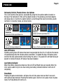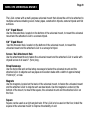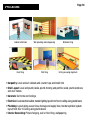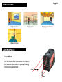
1
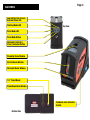
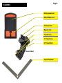
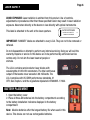
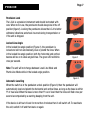
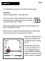
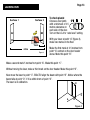
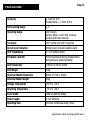
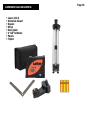
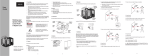
LCL4SET User Guide
Page 2
CONTENTS
Contents:
3.Warranty
4.Features
6.
Laser Safety & Battery Placement
7.Operation
9.
Using the Universal Mount
10.Applications
11.
Laser Offsets
12.Calibration
14.Specifications
15.
Care & Maintenance
16.
Standard Accessories
WARRANTY
Page 3
Limited Lifetime Guarantee
Apex Tool Group quality products are Guaranteed against any defect in material or workmanship. Damage caused by abuse, improper use or excessive wear is not covered by this
warranty.
This warranty is provided in addition to other rights and remedies you have under law: Our
goods come with guarantees that cannot be excluded under the Australian Consumer Law.
You are entitled to a replacement or refund for a major failure and for compensation for
any other reasonably foreseeable loss or damage. You are also entitled to have the goods
repaired or replaced if the goods fail to be of acceptable quality and the failure does not
amount to a major failure.
Claims should be returned, with proof of purchase, to the place of purchase or returned
prepaid to the address below. Repaired or replacement goods will be returned at our cost.
Apex Tool Group Pty Limited
519 Nurigong Street, Albury
NSW 2640, AUSTRALIA
Ph: (02) 60580300
[email protected]
www.apextoolgroup.com.au
Page 4
FEATURES
Low battery, Out of Level,
External Power LED
Working Mode LED
Top View
Pulse Mode LED
Pulse Mode Button
Horizontal, Vertical &
Cross Line Select Button
Plumb Up Beam Window
Vertical Beam Window
Horizontal Beam Window
1/4” Tripod Mount
Plumb Down Beam Window
Pendulum Lock & Control
Switch
Bottom View
Page 5
FEATURES
Battery compartment
External Power 4.5V DC
Attachment Hole
Magnetic Back
Strap Raceway
1/4” Tripod Screw
5/8” Tripod Mount
Universal Mount
Square Attachment
Page 6
LASER SAFETY
AVOID EXPOSURE: Laser radiation is emitted from this product. Use of controls,
adjustments or procedures other than those specified herein may result in laser radiation
exposure. Never stare directly at the beam or view directly with optical instruments.
This label is attached to the unit at the laser aperture.
AVOID EXPOSURE
LASER LIGHT IS EMITTE
FROM THIS APERTURE
D
IMPORTANT: “DANGER” labels are attached to every LCL4. They are not to be removed or
defaced.
Do not disassemble or attempt to perform any internal servicing. Doing so will void the
warranty. Repairs or service to this device are to be performed by authorized service
centres only. Do not aim the laser beam at people or
animals.
The LCL4 contains semiconductor laser diodes with
wavelengths of 635-650 nanometers. The total continuous
output of the beams never exceeds 4.99 milliwatts. The
LCL4 complies with US CDRH performance standards, 21
CFR, Sub chapter J and the regulations stipulated in EN60825-1/1994.
BATTERY PLACEMENT
1. Open the battery cover
2. Place all three AA batteries into the battery compartment according
to the battery installation indicators displayed in the battery
compartment.
Note: Alkaline batteries offer the longest battery life when used in this
device. This device can not use rechargeable batteries.
OPERATION
Pendulum Lock
The LCL4 is a precision instrument and should be treated with
care. When not in use, the pendulum should always be in the off
position (figure1). Locking the pendulum allows the LCL4 to better
withstand vibrations and shock incurred during transportation or
if the unit is dropped.
Locked Line Angle
In the locked line angle position (Figure 2), the pendulum is
locked and will not automatically level or plumb the lines. When
in the locked line angle position, both the horizontal and vertical
beams will be on to allow angled lines. The green LED will blink
once per second.
Page 7
Figure 1
Figure 2
Note: The unit will not change between Level Line Mode and
Plumb Line Mode while in the locked angle position.
Figure 3
Automatic Levelling
When the switch is in the pendulum unlock position (Figure 3) then the pendulum will
automatically level and plumb the horizontal and vertical lines, so long as the base is within
5º of true level. When the base is more than 5º out of level then the lines will flash once per
second accompanied by a warning beeping from the unit.
If the device is left out of level for more than 3 minutes then it will switch off. To reactivate
the unit, switch it off and then back on again.
Page 8
OPERATION
Horizontal, Vertical, Plumb & Cross Line Options
The LCL4 has three line options, accessible by using the line options button located on
the top of the instrument. If the unit has been turned on, the plumb up and down beams
will always be on. Use the line option button to cycle through the level (horizontal), plumb
(vertical) or cross line modes, as shown below.
Default line
Horizontal & Plumb up and down line
Press 1x
Vertical & Plumb up and down line
Press 2x
Cross & Plumb up and down line
Cross & Plumb up and down line locked
Auto-Off Feature
A battery saving Auto-Off feature has been incorporated into the LCL4. It will shut the device
off automatically after 60 minutes unless overridden. To disable the Auto-Off feature press
and hold the line options button when turning the unit on. The green LED will flash twice per
second to indicate the Auto-Off feature has been disabled.
Low Battery Indicator
When the battery charge becomes low, the red LED will flash twice per second. Note: the
LCL4 can be used for up to one hour during low battery indication before it will turn off
completely.
Pulse Mode
Pressing the pulse mode button, will place the unit into pulse mode so that it can work
with optional laser detector. Pressing the button again, returns to non-pulse mode. In pulse
mode, the Pulse Mode LED will be on.
USING THE UNIVERSAL MOUNT
Page 9
The LCL4 comes with a multi-purpose universal mount that allows the unit to be attached to
multiple surfaces including wood, metal, pipes, construction tripods, camera tripods and flat
surfaces.
1/4” Tripod Mount
Use the threaded hole, located on the bottom of the universal mount, to mount the universal
mount and the attached LCL4 to a camera tripod.
5/8” Tripod Mount
Use this threaded hole, located on the bottom of the universal mount, to mount the
universal mount and the attached LCL4 to a surveyor’s tripod.
Screw / Nail Attachment Hole
Use the attachment hole to fasten the universal mount and the attached LCL4 to walls with
drywall screw of at least 2” (5cm) long.
Strap Raceways
Use the horizontal and vertical strap raceways to fasten the universal mount and the
attached LCL4 to objects such as pipes and wooden studs with a width of approximately
150mm (6”) or less
Magnets
Use the magnets, located on the back of the universal mount, to fasten the universal mount
and the attached LCL4 to objects such as steel studs. Use the magnets. Located on the
bottom of the mount, to mount the square, the universal mount and the attached LCL4 on
the floor.
Square
Square can be used as a right-angled ruler. If the LCL4 is to be used on the floor, install the
square in the universal mount to improve the stability of unit.
Page 10
APPLICATIONS
Cabinet installation
Wall panelling and wallpapering
Bathroom tiling
Floor tiling
Wall tiling
Drilling & sawing alignment
• Carpentry: Level and set cabinets and counter tops and Install trim
• Stair Layout: Level and plumb decks, plumb framing and partition walls, plumb windows and door frames
• Concrete: Set forms and footings
• Electrical: Level electrical outlets, transfer lighting layout from floor to ceiling using plumb beam
• Plumbing: Layout piping, sewer lines, drainage and supply lines, transfer sprinkler system
layout from floor to ceiling using plumb beam
• Interior Decorating: Picture hanging, wall or floor tiling, wallpapering
Page 11
APPLICATIONS
Hanging pictures
Aligning shelves
Hanging pendant lamps
Window framing
LASER OFFSETS
Laser Offsets
Use the laser offset information provided in
the adjacent illustration to speed plumbing
and levelling operations.
28mm
32mm
Page 12
CALIBRATION
It is recommended that you check your LCL4 periodically to assure its accuracy.
To check level:
Choose two walls approximately 4 - 5 metres apart (figure 1).
Turn on the LCL4 to the “auto level” setting. With the laser 15cm away
from and facing Surface 1, carefully mark the center of the line where
the lines cross. Label this mark “A1” (figure 1).
Swivel the laser 180 degrees and mark the center of the line where the lines cross on
Surface 2. Label this mark “B1” (figure 1).
Now move the laser 15cm away from and facing Surface 2 (figure 2). Carefully mark the
center of the line where the line cross. Label this mark “B2” (figure 2).
Surface 1
Surface 2
A1
B1
x
x
15cm
4-5m
Figure 1
Swivel the laser 180 degrees and mark
the center of the line where the lines
cross on Surface 1 (figure 2). Label this
mark “A2”.
Next. Measure the distance between
“A1” and “A2” and between “B1” and
“B2”. If the distances are the same,
the unit is calibrated. If the differences
between the two sets of marks is greater
than 3mm the laser is out of calibration.
Page 13
CALIBRATION
Surface 1
Surface 2
A2
B2
x
x
15cm
4-5m
Figure 2
To check plumb:
Choose a door jamb
with a minimum of 2.5
metres clearance on
each side of the door.
Turn on the LCL4 to “auto level” setting.
With your laser at point “A” (figure 3),
make two marks on the floor.
Make the first mark at 2.5 metres from
point “A” centred on the door header
above. Mark this point “B”.
Make a second mark 5 metres from point “A”. Make this point “C”.
Without moving the laser, make a third mark on the door header. Make this point “D”.
Now move the laser to point “C”. EXACTLY align the beam with point “B”. Notice where the
beam falls at point “D”. If it is within 4mm of point “D”.
The laser is in calibration.
D
C
A
B
Figure 3
Page 14
SPECIFICATIONS
Accuracy
± 3mm @ 10m
Plumb beams: ± 1.5mm @ 5m
Self-levelling Range
± 5°
Operating Range
30m indoors
Outdoor Mode - Up to 50m outdoors,
working with laser detector
Fan Angle
140° vertical and 130° horizontal
Out-of-level Indication
Blinking laser lines and audible alarm
Unit Tripod Mount
¼” x 20 camera tripod
Pendulum Lock/Off
Protects pendulum during transportation
and storage for added durability
Unit Dimensions
110mm x 57mm x 97mm
Unit Weight
470g
Universal Mount Dimensions
89mm x 57mm x 46mm
Universal Mount Weight
200g
Storage Temperature
-20°C to +70°C
Operating Temperature
-10°C to +50°C
Laser Diode
Class IIIA 635nm diodes
Power Supply
3 “AA” batteries
Operating time
12 hours continuous using 2 lines
Specifications subject to change without notice.
CARE & MAINTENANCE
Page 15
This device is a product of precision design and manufacture and should be treated with
care. The suggestions below will help the user fulfill any warranty obligations and also allow
the user to enjoy this product for many years.
When using the device:
Keep it and all its parts and accessories out of small children’s reach.
This laser is built to be operated under wet conditions (IEC 529;IP 54), however the unit
should always be dried off before storage.
Do not store in hot areas. High temperatures can shorten the life of electronic devices, damage batteries, and warp or melt certain plastics.
Do not store in cold areas. When the device warms up to its normal operating temperature,
moisture can condense inside where it may damage circuit boards.
Although the LCL4 is dust and dirt resistant, do not store in dusty, dirty areas as long-term
exposure to these elements may damage internal moving parts.
Do not attempt to open the LCL4. Non-expert handling of the device may cause damage and
will void the warranty.
Do not drop, knock, or shake the LCL4. Rough handling can break the unit or compromise
its functionality.
Do not use harsh chemicals, cleaning solvents, or strong detergents to clean the LCL4. Wipe
it with a soft cloth, slightly dampened in a mild soap and water.
Keep the laser aperture windows clean by periodically wiping them with a cotton swab
dipped in isopropyl alcohol.
STANDARD ACCESSORIES
• Laser (LCL4)
• Universal mount
• Square
• Strap
• User guide
• 3 “AA” batteries
• Pouch
• Tripod
Page 16
Apex Tool Group Pty Limited
519 Nurigong Street, Albury
NSW 2640, AUSTRALIA
Ph: (02) 60580300
[email protected]
www.apextoolgroup.com.au
Issue: 0708829B