1
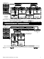
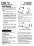
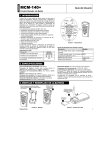
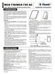
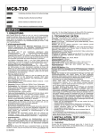
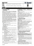
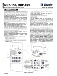
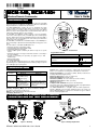
MCMMCM-140, MCMMCM-140+ User’s Guide Wireless Remote Commander 1. INTRODUCTION The MCM-140/MCM-140+ is a wireless remote control unit for the PowerMax family control panels. The MCM-140 and MCM-140+ differ in their transmitted ID type and functions, as detailed in the Specifications. The MCM-140/MCM-140+ enables the user to arm/disarm the alarm system, to initiate emergency/fire/panic alarms, to perform one of the AUX (auxiliary) functions (see Note 2 and 3 in Section 7) and to turn lighting devices on and off. The keypad includes an RF transmitter that sends out a differently coded RF signal for each command. For PowerMax, the MCM-140 enables activation of the Aux (Auxiliary), seven home control outputs (X-10), one PGM output, Fire and Emergency functions. Each button needs to be individually defined for the AUX, PGM or X-10 functions at the corresponding points of the define panel and define outputs menu of the control panel. For PowerMax+, PowerMax Pro, PowerMaxComplete or PowerMaxExpress all the functionality is implemented automatically without using space of the zones. The main features of the MCM-140/MCM-140+ are: • Automatic reporting of low battery voltage. • Visual indications by red/green/amber LED. • Keypad back lighting (selectable). • Various audible signals sounded by the buzzer in response to specific actions. • Automatic supervision messages at 60 minute intervals or according to the local standards. • Long-life 3 year battery life expectancy (for typical user) 3 VDC lithium battery. • Wall mounting option. • Friendly programming. The red LED lights during transmission. The amber LED lights during the programming process (and during transmission if battery voltage is low). The green LED lights upon each keystroke. 3-color LED Buzzer Light Away 2 Home Off 5 8 Aux * Emergency 0 # Prog. mode Fire Panic Figure 1 - External View Keypad Buzzer Sound Description Symbol Short single beep, upon pressing a key 2 short beeps, in the programming process (par. 4.3 & 4.5) Success (victory) melody Failure beep 2. SPECIFICATIONS Transmitted ID Type and Functions: Transmitted Functions ID Type MCM-140 MCM-140+ Used for Lights 1-7, PowerCode Light 8 (PGM control), Fire and Emergency functions Home arming, Away arming, CodeSecure CodeSecure - Used for Home arming, Away Disarming, Aux, Panic (*), arming, Disarming, Aux Lights 1-7, Duress, Fire and and Panic (*) functions Emergency. * Panic alarm is not operative in ACPO compliant products (UK). Operating Frequency (MHz): 315, 433.9 and 868.95, 869.2625 or according to requirement in country of use. Battery: 3 VDC, Lithium battery 1450 mA/h, CR123A Low Battery Threshold: 2.7V Caution! Risk of explosion if battery is replaced by an incorrect type. Dispose of used batteries according to the manufacturer's instructions. Current Consumption: 10 µA approx. (STBY), 95mA (in transmission, including LED and back light currents) Battery Life Expectancy: 3 years (for typical use) Back light illumination: Selectable on/off Dimensions (HxWxD): 127 x 70 x 24 mm (5 x 2-3/4 x 31/32 in.) Operating Temperatures: 0°-49°C (32°-120°F) Weight: 105g (3.7oz) Compliance with Standards: FCC part 15, IC:1467102181. The term "IC" before the certification/registration number only signifies that the Industry Canada technical specifications were met. The MCM-140/MCM-140+ is compatible with the RTTE requirements Directive 1999/5/EC of the European Parliament and of the Council of 9 March 1999 and EN50131-1, EN 50131-3, EN 50131-6, Type C Grade 2 Class II. Certified by Applica T&C. 3. MOUNTING AND BATTERY REPLACEMENT Drill 2 holes in mounting surface, insert wall anchors and fasten the bracket with 2 screws Slide the keypad into the bracket 1 2 Replace battery (verify proper polarity) and close cover 2 Slide out the cover 1 Figure 2 - Mounting DE2461U MCM-140, MCM-140+ User’s Guide Figure 3 - Battery Replacement 1 Note: If the MCM-140/MCM-140+ is mounted near the site door, the PowerMax family control panel "Quick arming" function should be disabled, otherwise site security may be compromised. 4. PROGRAMMING 4.1 Programming Scope 4.4 Restoring the Default Master Code The following programming actions are possible: • Setting the master user (user #1) code. • Setting other user codes (users #2-8). • Allowing/forbidding quick arming of the keypad. • Muting/reactivating the keypad's buzzer. • Controlling the keypad's back-lighting. • Enabling/disabling the supervision/low battery reporting from the MCM-140/MCM-140+. If the master code is forgotten, it is possible to recall the factory default master code "1111". To ensure that this possibility is not misused by unauthorized people, a panic alarm is automatically transmitted to the PowerMax family control panels when such an action is performed. 4.2 Entering the Programming Mode To recall the default master code and prevent a panic alarm, set the PowerMax family control panels to Installer mode (see PowerMax programming guide and PowerMax+, PowerMax Pro, PowerMaxComplete and PowerMaxExpress installer guide) and proceed as shown in the following illustration: The programming mode is accessible with the master code only (1 1 1 1 by default). The "#" key is used to enter and also to exit the programming mode. Entering the Programming Mode Action + +[master code] (1111 by default) LED indication Buzzer response Green LED blinks slowly until the master code is keyed * Amber LED blinks slowly during programming * (success melody) 4.5 Special Programming Options Quick arm AWAY ON and HOME ON (default OFF) #, Note Upon entering the programming mode, the success melody is heard and the amber LED starts blinking. Blinking will stop once you exit from this mode (by pressing "#" again) or upon time out during which no key is pressed. 2 short beeps are heard when the LED stops blinking. #, LED indication #, +[new code] #, [master code] (amber LED blinks), 9, 1, OFF * [master code] (amber LED blinks), 9, 2, AWAY * [master code] (amber LED blinks), 9, 2, OFF * Back lighting ON (default ON) Buzzer response #, Amber LED blinks quickly (blinks slowly after success) AWAY * Buzzer OFF Amber LED blinks 2 1, Buzzer ON (default ON) To change the MCM-140/MCM-140+ master and user codes, proceed as follows: Action 9, Quick arm OFF 4.3 Changing Master/User Codes +[1-8]1 [master code] (amber LED blinks), [master code] (amber LED blinks), 9, 3, AWAY * Back lighting OFF #, (success melody) Notes 1. Enter user No. (1-8). User No. 1 is defined as the master user. 2. Master/user codes consist of 4-digits. Code "0000" is not valid. It can be used to erase the currently programmed code (when this action is performed, success melody is heard). 3. The PowerMax family control panels user codes and MCM-140/MCM140+ user codes are different codes. 4. Disarming actions that are performed by users 5-8 are considered as latchkey disarming. The LATCHKEY option should be enabled in PowerMax family control panels. [master code] (amber LED blinks), 9, Important: In the following processes, the instruction 140 only. For MCM-140+ use 3, OFF * 4 is for MCM- 5 instead. Supervision / Low battery reporting ON (default OFF) ** #, [master code] (amber LED blinks), 9, 4, AWAY * Supervision / Low battery reporting OFF #, [master code] (amber LED blinks), 9, 4, OFF * * To indicate success, the amber LED blinks and the buzzer sounds twice. ** The supervision message is sent once an hour or according to local standards. *** When there is Low Bat condition, trouble message will be displayed for the zone that was selected for FIRE key. 5. ENROLLING/DELETING MCMMCM-140/MCM 140/MCM/MCM-140+ IN POWERMAX 5.1 Enrolling Arming, Disarming, Aux and Panic Functions To enroll the Home/Away arming, Disarming, Aux and Panic functions, refer to figure 4A. Note: If you are using the latchkey feature, and keyfob locations (5-8) are programmed with an MCM-140/MCM-140+, then all disarming actions performed by the MCM-140/MCM-140+ will be considered latchkey disarming. 5.2 Enrolling Lights, Fire, Emergency Functions and For the enrolling, refer to figure 4A Note Define the zones that are enrolled with X-10 and PGM devices as "nonalarm" zones, to prevent an alarm display when the device is activated. 5.3 Programming PGM/X-10 Devices as "On by Zones" (MCM-140) To enable activation of PGM/X-10 devices from the MCM-140/MCM-140+, they must be programmed as "On by Zones". For the programming process, refer to the PowerMax programming guide (Defining Output Parameters). The following MCM-140 (not MCM-140+) PowerCode control functions can be enrolled: X-10 devices ( 1-7), PGM output (activated by ). Fire and Emergency. 2 DE2461U MCM-140, MCM-140+ User’s Guide (First display is READY or NOT READY) ENROLL WL DEVICE NEXT READY 00:00 NEXT Zone No: Enter zone # to which you want to enroll your 1st X-10 device, e.g. 23 NORMAL MODE NEXT USER SETTINGS NEXT Zone No: 23 TRANSMIT NOW INSTALLER MODE OK ENROLL KEYFOB OK keyfob No: OK <OFF> TO DELETE ENTER CODE [installer code] 1. NEW INSTL CODE NEXT 2. ENROLLING OK press LIGHT key followed by “1” (for X-10 device #1) (**) (*) Black rectangle means that that it is already enrolled. Enter location # 1 to 8] (e.g. 5) (*) Zone No : 23 OK keyfob No : 5 TRANSMIT NOW press “*” key (∼2 sec.) until red LED lights) Zone No: 23 Zone No: 23 NEXT for next enrolling action Deleting LIGHTS, FIRE & EMERGENCY functions OK <OFF> TO DELETE (**) NEXT for next enrolling action (*) keyfob No : 5 OK keyfob No: 5 Enrolling LIGHTS, FIRE & EMERGENCY functions NEXT OK Enrolling Arming, disarming, Aux and Panic functions keyfob No: 5 Deleting Arming, disarming, Aux and Panic functions (**) If the same function is already enrolled elsewhere, the “Happy Tune” will sound twice in succession. Note: The MCM-140+ can be enrolled by using the ENROLL KEYFOB menu (to enable using it for arming, disarming, AUX and Panic functions). The MCM-140+ can not be enrolled by using the ENROLL WL DEVICE menu. Figure 4A – Enrolling / Deleting a MCM-140 and MCM-140+ functions in PowerMax PowerMax Memory 6. ENROLLING MCMMCM-140 / MCMMCM-140+ in POWERMAX+ POWERMAX+ / POWERMAX PRO / POWERMAXCOMPLETE / POWERMAXEXPRESS To enroll all the MCM-140/MCM-140+ functions (for details, see specifications), enter the PowerMax+ / PowerMax Pro / PowerMaxComplete / PowerMaxExpress Installer Mode and proceed as shown in the following illustration. To enroll the AUX, X-10, Fire and Emergency functions of the MCM140 (sent as PowerCode messages) each button need to be enrolled to a separate zone that has selected the required settings. (First display is READY ENROLLING TYPE NEXT ENROLL WL DEVICE NEXT ENROLL KEYFOB NEXT or NOT READY) READY 00:00 NEXT NEXT ENROL WL 1WAY KP NEXT ENROL WL 2WAY KP NEXT ENROL WL SIREN NEXT ENROL PROX TAG NORMAL MODE NEXT USER SETTINGS No. 1 to 8] [MCM-140+ (e.g. 5) NEXT INSTALLER MODE 1way kp No : 5 OK ENTER CODE [installer code] 2. ENROLLING OK TRANSMIT NOW 1. NEW INSTL CODE NEXT OK 1way kp No : OK press “*” key until red LED lights 1way kp No : 5 OK Black rectangle means that the MCM-140+ No. 5 is already enrolled. (PowerMax Pro & PowerMaxComplete only) <OFF> TO DELETE 1way kp No: 5 1way kp No: 5 NEXT for next enrolling action Enrolling a wireless Commander MCM-140+ Deleteing a wireless Commander MCM-140+ Figure 4B – Enrolling/Deleting a MCM-140 and MCM-140+ in PowerMax+ / PowerMax Pro / PowerMaxComplete / PowerMaxExpress Memory Note: The PowerMax+ buttons NEXT & OK are represented in PowerMax Pro, PowerMaxCompletre and PowerMaxExpress by & , buttons, respectively. DE2461U MCM-140, MCM-140+ User’s Guide 3 7. OPERATION This can be selected in the "PGM/X-10 Time" under "4. Define Panel" in the installer mode (refer to the PowerMax programming guide). The setting process is described in the installer guide. 3. The AUX function works just like the [∗] key in the keyfob. Pressing The following table describes how to activate the various functions. Function Arming HOME Actions (1) Arming AWAY Disarming X-10 device (1-7) ON (9) X-10 device (1-7) OFF LIGHT OFF Duress (option) LIGHT [8] Duress (option) LIGHT OFF AUX Function (9) (9) (≈ 2 sec.) Emergency alarm (≈ 2 sec.) (6) Fire alarm (≈ 2 sec.) (6) Panic alarm (≈ 2 sec.) (6) Latchkey arming Quick arm / HOME .... [8] (9) (2) (3) (≈ 2 sec.). (LED blinks, then lights RED during transmission) Notes 1. Eight user codes are possible (user code # 1 is the master user code). Factory default master code is "1111". Upon entering a valid code or a valid command, the success (victory) melody is heard and the red LED lights briefly (transmission indication). 2. Pressing followed by the desired X-10 device number (1-7) turns on this device (success beeps are heard). Performing these actions again turns this device off. In order for the X-10 device to be turned off when the light key is pressed the second time, the Toggle mode must be selected. (≈ 2 sec.) can initiate the the Auxiliary Function key STATUS action (system status announcement), the INSTANT action (entry delay cancellation) or the PGM action (activation of PGM output or X-10 units), depending on prior installer programming. For selecting the desired auxiliary function, refer to the installer guide, belonging to the respective control panel you are using. 4. For LATCHKEY arming function, press the AWAY key, wait until the red LED extinguishes, then press the AWAY key again. The red LED lights and extinguishes again. From PowerMax version V1.16: For Latchkey disarming, the MCM140/MCM-140+ can be learned into the PowerMax as user 5, 6, 7 or 8. You can use the MCM code 1, 2, 3, 4, 5, 6, 7, or 8. 5. Pressing a non-valid code combination (not master / user code) causes a long failure beep. 6. If a keying sequence is not completed within timeout, the desired function will not be executed. 7. Pressing the Emergency, Fire or Panic buttons, causes the red and green LEDs to blink alternately for 2 seconds to alert the user. The red LED lights during transmission. The panic function can be programmed (enabled or disabled) by the installer. 8. If arming Home or arming AWAY command is used with an invalid user code, the command will not be performed. To enter the arming HOME/AWAY command again, you have 2 choices: a. Wait until time out to expire and the green LED stops blinking. Then try again. b. Press HOME/AWAY twice, then enter user code again. 9. In control panels where partition is enabled, the X-10 cannot be operated by the MCM-140+. In this case, the button is used to select between Partitions 1, 2, or 3. Refer to the PowerMax control panel for instructions on how to arm a single partition. 8. COMPLIANCE WITH STANDARDS This device complies with the essential requirements and provisions of Directive 1999/5/EC of the European Parliament and of the Council of 9 March 1999 on radio and telecommunications terminal equipment. Frequency Allocations European Countries: for Wireless Devices in • 433.92 MHz has no restriction in any EU member state. • 315 MHz is not allowed in any EU member state. • 868.95 MHz (wide band) is allowed in all EU member states. • 869.2625 MHz (narrow band) is not restricted in any EU member state. The user is cautioned that changes or modifications to the unit, not expressly approved by Visonic Ltd., could void the user's FCC or other authority to operate the equipment. The 315 MHz model of this device complies with Part 15 of the FCC Rules and RSS-210 of Industry and Science Canada. Operation is subject to these two conditions: (1) This device may not cause harmful interference, and (2) this device must accept any interference received, including interference that may cause undesirable operation. WARRANTY Visonic Limited (the “Manufacturer") warrants this product only (the "Product") to the original purchaser only (the “Purchaser”) against defective workmanship and materials under normal use of the Product for a period of twelve (12) months from the date of shipment by the Manufacturer. This Warranty is absolutely conditional upon the Product having been properly installed, maintained and operated under conditions of normal use in accordance with the Manufacturers recommended installation and operation instructions. Products which have become defective for any other reason, according to the Manufacturers discretion, such as improper installation, failure to follow recommended installation and operational instructions, neglect, willful damage, misuse or vandalism, accidental damage, alteration or tampering, or repair by anyone other than the manufacturer, are not covered by this Warranty. The Manufacturer does not represent that this Product may not be compromised and/or circumvented or that the Product will prevent any death and/or personal injury and/or damage to property resulting from burglary, robbery, fire or otherwise, or that the Product will in all cases provide adequate warning or protection. The Product, properly installed and maintained, only reduces the risk of such events without warning and it is not a guarantee or insurance that such events will not occur. THIS WARRANTY IS EXCLUSIVE AND EXPRESSLY IN LIEU OF ALL OTHER WARRANTIES, OBLIGATIONS OR LIABILITIES, WHETHER WRITTEN, ORAL, EXPRESS OR IMPLIED, INCLUDING ANY WARRANTY OF MERCHANTABILITY OR FITNESS FOR A PARTICULAR PURPOSE, OR OTHERWISE. IN NO CASE SHALL THE MANUFACTURER BE LIABLE TO ANYONE FOR ANY CONSEQUENTIAL OR INCIDENTAL DAMAGES FOR BREACH OF THIS WARRANTY OR ANY OTHER WARRANTIES WHATSOEVER, AS AFORESAID. THE MANUFACTURER SHALL IN NO EVENT BE LIABLE FOR ANY SPECIAL, INDIRECT, INCIDENTAL, CONSEQUENTIAL OR PUNITIVE DAMAGES OR FOR LOSS, DAMAGE, OR EXPENSE, INCLUDING LOSS OF USE, PROFITS, REVENUE, OR GOODWILL, DIRECTLY OR INDIRECTLY ARISING FROM PURCHASER’S USE OR INABILITY TO USE THE PRODUCT, OR FOR LOSS OR DESTRUCTION OF OTHER PROPERTY OR FROM ANY OTHER CAUSE, EVEN IF MANUFACTURER HAS BEEN ADVISED OF THE POSSIBILITY OF SUCH DAMAGE. THE MANUFACTURER SHALL HAVE NO LIABILITY FOR ANY DEATH, PERSONAL AND/OR BODILY INJURY AND/OR DAMAGE TO PROPERTY OR OTHER LOSS WHETHER DIRECT, INDIRECT, INCIDENTAL, CONSEQUENTIAL OR OTHERWISE, BASED ON A CLAIM THAT THE PRODUCT FAILED TO FUNCTION. However, if the Manufacturer is held liable, whether directly or indirectly, for any loss or damage arising under this limited warranty, THE MANUFACTURER'S MAXIMUM LIABILITY (IF ANY) SHALL NOT IN ANY CASE EXCEED THE PURCHASE PRICE OF THE PRODUCT, which shall be fixed as liquidated damages and not as a penalty, and shall be the complete and exclusive remedy against the Manufacturer. When accepting the delivery of the Product, the Purchaser agrees to the said conditions of sale and warranty and he recognizes having been informed of. Some jurisdictions do not allow the exclusion or limitation of incidental or consequential damages, so these limitations may not apply under certain circumstances. The Manufacturer shall be under no liability whatsoever arising out of the corruption and/or malfunctioning of any telecommunication or electronic equipment or any programs. The Manufacturers obligations under this Warranty are limited solely to repair and/or replace at the Manufacturer’s discretion any Product or part thereof that may prove defective. Any repair and/or replacement shall not extend the original Warranty period. The Manufacturer shall not be responsible for dismantling and/or reinstallation costs. To exercise this Warranty the Product must be returned to the Manufacturer freight pre-paid and insured. All freight and insurance costs are the responsibility of the Purchaser and are not included in this Warranty. This warranty shall not be modified, varied or extended, and the Manufacturer does not authorize any person to act on its behalf in the modification, variation or extension of this warranty. This warranty shall apply to the Product only. All products, accessories or attachments of others used in conjunction with the Product, including batteries, shall be covered solely by their own warranty, if any. The Manufacturer shall not be liable for any damage or loss whatsoever, whether directly, indirectly, incidentally, consequentially or otherwise, caused by the malfunction of the Product due to products, accessories, or attachments of others, including batteries, used in conjunction with the Products. This Warranty is exclusive to the original Purchaser and is not assignable. This Warranty is in addition to and does not affect your legal rights. Any provision in this warranty which is contrary to the Law in the state or country were the Product is supplied shall not apply. Warning! The user must follow the Manufacturer’s installation and operational instructions including testing the Product and its whole system at least once a week and to take all necessary precautions for his/her safety and the protection of his/her property. 01/08 W.E.E.E. Product Recycling Declaration For information regarding the recycling of this product you must contact the company from which you orignially purchased it. If you are discarding this product and not returning it for repair then you must ensure that it is returned as identified by your supplier. This product is not to be thrown away with everyday waste. Directive 2002/96/EC Waste Electrical and Electronic Equipment. EMAIL: [email protected] INTERNET: www.visonic.com VISONIC LTD. 2014 MCM-140/MCM-140+ 4 DE2461U (Rev 6, 9/14) DE2461U MCM-140, MCM-140+ User’s Guide