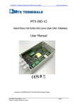
Download HOBO U30 Station Remote Communication User's Guide
Transcript
OnsetComputerCorp Contacting Onset Forsupport,pleasecontactthecompanythatyouboughttheproductsfrom:OnsetComputer CorporationoranOnsetAuthorizedDealer. OnsetComputerCorporation 470MacArthurBlvd. Bourne,MA02532 MailingAddress: P.O.Box3450 Pocasset,MA02559‐3450 Phone:1‐800‐LOGGERS(1‐800‐564‐4377)or508‐759‐9500 Fax:508‐759‐9100 CustomerServiceHours:8AMto5PMEasternTime TechnicalSupportHours:8AMto8PMEasternTime Email:[email protected]@onsetcomp.com MainOnsetWebsite:www.onsetcomp.com Copyrights and Trademarks ©2009–2012OnsetComputerCorporation.Allrightsreserved.Onset,HOBO,HOBOlink, HOBOware,BoxCar,andFlexSmartaretrademarksorregisteredtrademarksofOnset ComputerCorporationforitsdataloggerproductsandconfiguration/interfacesoftware. MacintoshisaregisteredtrademarkofApple,Inc.MicrosoftandWindowsareregistered trademarksofMicrosoftCorporation.Allothertrademarksarethepropertyoftheirrespective companies. Doc#:12269‐J Part#:MAN‐U30‐RC‐UG HOBOU30/RC ‐ii‐ User’sGuide OnsetComputerCorp Contents About the HOBO U30 Station .............................................................. 1 Introduction...................................................................................................................................................1 KeyFeatures..................................................................................................................................................2 U30StationComponents..........................................................................................................................3 Software...........................................................................................................................................................5 SmartSensors................................................................................................................................................6 TheAnalogSensorPort.............................................................................................................................7 Setup and Test ................................................................................... 9 ConfigurationSummaries.........................................................................................................................9 InitialHOBOlinkSetup............................................................................................................................11 InitialHardwareSetup...........................................................................................................................12 ConnectingtheHOBOU30StationtoHOBOwarePro...............................................................13 ConfiguringAnalogSensorPortsoraTRMSAModule..............................................................14 ChangingtheStateoftheU30RelayContact................................................................................16 BasicHardwareSetup.............................................................................................................................17 FinalHOBOlinkSetupandTest...........................................................................................................18 InstallingMountingPlates....................................................................................................................19 ConnectingSmartSensors....................................................................................................................20 ConnectingAnalogSensors...................................................................................................................22 ConnectingtheBattery...........................................................................................................................23 Network Settings ............................................................................. 24 ConfiguringWirelessNetworkSettings..........................................................................................24 ConfiguringaStaticIPAddress...........................................................................................................28 Installing the U30 Station in the Field.............................................. 30 FieldInstallationProcedure.................................................................................................................30 ConnectingGroundingWire.................................................................................................................32 InstallingWeatherproofCableChannels........................................................................................33 ConnectingSolarorACPower.............................................................................................................36 ConnectingEquipmenttotheRelayContact.................................................................................37 MountingtheHOBOU30StationtoaPole.....................................................................................38 CheckingCellularSignalStrength(U30/GSM).............................................................................39 HOBOU30/RC ‐iii‐ User’sGuide OnsetComputerCorp The U30 Relay Contact ..................................................................... 40 AnOverviewoftheU30RelayContact............................................................................................40 RelayExample‐StartDevice...............................................................................................................42 RelayContactExample‐StopDevice...............................................................................................43 ConfiguringRelayAlarmsfortheU30/RC.....................................................................................44 ChangingtheStateoftheU30RelayContact................................................................................46 ConfiguringRelayAlarmsfortheU30/RC.....................................................................................47 Maintenance..................................................................................... 49 GeneralMaintenance...............................................................................................................................49 AddingaSensor.........................................................................................................................................51 Removing/ReplacingaSensor............................................................................................................52 TestingSmartSensors............................................................................................................................52 CheckingtheU30Status........................................................................................................................52 InspectingtheHOBOU30Station......................................................................................................53 TroubleshootingtheHOBOU30Station.........................................................................................54 The Smart Sensor Expander Board ................................................... 56 OpeningtheSecondaryCableSlot.....................................................................................................56 InstallingtheExpanderBoard.............................................................................................................58 The Battery ...................................................................................... 60 Overview.......................................................................................................................................................60 BatteryLife..................................................................................................................................................61 MaximizingBatteryLife.........................................................................................................................62 BatteryVoltage..........................................................................................................................................63 ConnectingtheBattery...........................................................................................................................65 MaintainingtheBattery.........................................................................................................................66 ReplacingtheBattery..............................................................................................................................66 TroubleshootingtheBattery................................................................................................................67 BatteryLifewithoutExternalPower................................................................................................68 Reference ......................................................................................... 69 GeneralU30Specifications...................................................................................................................69 GSM/Wi‐FiSpecifications......................................................................................................................71 AnalogSensorPort...................................................................................................................................72 TimeAccuracy............................................................................................................................................74 HOBOU30/RC ‐iv‐ User’sGuide OnsetComputerCorp Memory.........................................................................................................................................................75 ConnectionStatusLEDs.........................................................................................................................76 LoggerStatusLEDs...................................................................................................................................78 ItemsRequiredforFieldInstallation................................................................................................79 Accessories..................................................................................................................................................80 FCCPart15Compliance.........................................................................................................................81 Wi‐FiCompliance......................................................................................................................................82 EthernetCompliance...............................................................................................................................83 Tripod Setup .................................................................................... 84 GuidelinesforTypicalFieldSetup.....................................................................................................84 FieldPreparationChecklist..................................................................................................................86 ItemsRequiredforInstallation...........................................................................................................87 Task1:AssembleTripod.......................................................................................................................89 Task2:InstallGroundingKit...............................................................................................................96 Task3:TemporarilyInstallUpperMast(Optional)...................................................................97 Task4:MountCrossArm(Optional)................................................................................................98 Task5:MountUpperMasttoLowerMast.....................................................................................99 Task6:MountLoggertoUpperMast.............................................................................................100 Task7:InstallGuyWireKit(Optional)..........................................................................................101 Task8:PositionandLevelSensors.................................................................................................102 Task9:FinalSetup.................................................................................................................................103 HOBOU30/RC ‐v‐ User’sGuide OnsetComputerCorp ABOUT THE HOBO U30 STATION Introduction Overview TheHOBOU30Stationisadataloggingandmonitoringdevicethatcanbeeasilyreconfigured andadaptedtoawidevarietyofapplications.Upto15channelsofdatacanberecordedand monitoredremotelyviaHOBOlink™. UseHOBOware®Prosoftwaretosetupanalogdatachannels,communicatewiththelogger locally,andperformadvancedplottingandanalysis. TheHOBOU30Stationisadataloggingsystemthatcanbeeasilyreconfiguredandadaptedto awidevarietyofapplications.Upto15channelsofdatacanberecordedandmonitoredwith HOBOwareProsoftware. Youcansetalarmstotripforspecificsensorreadingsthatyouselectorforoverallsystem conditions,suchaswhenthememoryorbatteryisrunninglow. Remote Communication Models TheHOBOU30StationisavailableinthreemodelsthatsupportRemoteCommunication: GSM Wi‐Fi Ethernet Note:TheHOBOU30/Wi‐FiworkswithallapprovedAccessPointRouterstandardsincluding typicalhomeIEEE802.11bandIEEE802.11gunits.Pre‐NandDraft‐Naccesspointroutersare ‘preliminary’andmaynotworkwiththeHOBOU30/Wi‐Fi. Contents TheHOBOU30Stationpackageincludes: HOBOU30Station MountingKit GroundingWire CableEntryandSealingKit OptionalAnalogSensorPort,ifordered OptionalSensorExpanderBoard,ifordered 1 OnsetComputerCorp Key Features Remote Communication TherearethreeversionsoftheU30thatallowforremotecommunicationusingHOBOlink.By usinganywebbrowser,youcanconfigureandviewdatafromtheHOBOU30Stationanywhere intheworld. GSM.TheHOBOU30/GSMcontainsaGlobalSystemforMobile(GSM)communications radiomodulethatusesthemobilephonenetworktoestablishaninternetconnection withHOBOlink. Wi‐Fi.TheHOBOU30/Wi‐Ficombinesruggedizeddatalogginghardwarewith integratedWi‐Ficommunications,andisversatileenoughtouseinbothindoorand outdoorenvironments.Userscaneasilyandquicklyplugintheirchoiceofsensorsand connecttoaWi‐Finetworkwithouthavingtoworryaboutcumbersome communicationscablesorwiring. Ethernet.TheHOBOU30/Ethernetallowsyoutoconnectdirectlytotheinternetusing anEthernetcable. Automatic Detection of Smart Sensors TheHOBOU30StationautomaticallyrecognizesSmartSensors.Youcanconnectupto10 SmartSensorsofanytypeorcombinationjustbypluggingtheminbeforeloggingbegins.No programming,wiringorcalibrationisrequiredtosetthemup.Theconnectionsbetweenthe SmartSensorsandtheloggeraredigital,ensuringaccurate,reliabledatacollectionand storage.TheHOBOU30RemoteMonitoringSystemiscompatiblewithallSmartSensorsused withtheHOBOWeatherStationandHOBOMicroStation. Alarm Notification TheHOBOU30Stationsupportsalarmnotificationforsensorsaswellassystemalarms.When analarmisdetected,thesystemcantriggertherelaycontactclosureandsendyoua notificationtoyouremail/mobilephone.Alarmscanbesetforindividualsensorsandfor overallsystemconditions. Rechargeable Battery TheHOBOU30StationusesaSealedLeadAcidbatterythatcanberechargedviaasolarpanel orACadapter.ThisprovidescontinuouspowertokeeptheHOBOU30Stationrecordingand transmittingdataforyears. Optional Analog Sensor Ports TheHOBOU30Stationcanbeoptionallyconfiguredwithtwoanalogsensorports.Theports areuser‐configurableandcanacceptandprovideexcitationpowertoawiderangeofOnset andthird‐partysensorswith0‐20Vor0‐20mAoutput.TheAnalogsensorportsarefactory‐ installed. 2 OnsetComputerCorp U30 Station Components ThistopicdescribesthecomponentsfortheHOBOU30Station.Somecomponentsapplyto specificmodelsonly,asnoted. Diagram Figure 1: U30 Components Component Descriptions 1. OuterCase‐ProtectstheU30Station. 2. Logger‐TheU30Station. 3. InternalCase–ThisweatherproofcaseprovidesasecondlevelofprotectionfortheU30 electroniccircuitry.Donotopenthiscase;doingsowillvoidthewarranty. 4. ExpansionPortConnector(shownwithoptionalAnalogSensorPortinstalled)‐This portiswheretheoptionalAnalogSensorPortsarefactory‐installed. 5. RelayContacts‐TheRelaycanbeactivated,deactivated,orpulsedonuser‐defined sensoralarms.Therelaycanbeconfiguredasnormallyopenornormallyclosed,andis ratedfor30V,1Ampmaximum. 6. USBPort‐PluginaUSBcableheretoconnectdirectlytoacomputer. 7. AntennaorEthernetPort‐AntennainstalledonGSMorWi‐Fimodels;Ethernet ConnectionfortheEthernetmodelonly. 8. Vent‐Thisventallowspressuretoequalizeinsidetheenclosure,butdoesnotallow liquidtopassthrough. 3 OnsetComputerCorp NOTE:Thepressureinsidethecasedoesnotmatchtheoutsideairpressureexactlysoa barometricpressuresensordeployedwithinthiscasecannotmeasurethetrue atmosphericpressureunlessithasitsownunrestrictedventtotheoutside. 9. SmartSensorExpansionSlot‐TheoptionalSmartSensorExpanderBoardisinstalled here. 10. Cableaccessopenings‐Allcablesandwiresarepulledthroughaprotectiverubber cablechannelplacedinthisopening.Ifusingtheoptionalfactory‐installedexpander boardforadditionalSmartSensors,youwillneedtousethesecondcableaccess opening. 11. SmartSensorPorts‐ConnectuptofiveSmartSensorsintheseRJ‐12jacks.Useonejack toconnecttheoptionalexpanderboardforadditionalSmartSensors. 12. RechargeableBattery‐4‐VoltSealedLeadAcid(SLA)batterylocatedinsidethecase. 13. BatteryConnector‐Pluginthe4‐VoltSealedLeadbatteryhere. 14. GroundConnector‐Plugingroundingwireheretogroundthesystem. 15. ExternalPowerSupplyConnector‐PluginthecompatiblesolarpanelorACadapter here. Important:Alwaysconnectordisconnectexternalpowerbeforethebattery.Damage mayoccurifthebatteryisunpluggedbeforetheexternalpowerisdisconnected. 16. StatusLEDs TherearethreeLightEmittingDiode(LED)statusindicators. Loggingindicateswhetherthesystemiscurrentlylogging. Alarmindicatesifanalarmhasbeentripped. SensoractiveindicatesthatSmartSensornetworkcommunicationsareoccurring. FormoreinformationonLEDs,refertoDiagnosticsandtroubleshooting. 17. ConnectionLEDs(RemoteCommunicationModelsonly) Top‐BlinkswhentheHOBOU30Stationisattemptingtocontactanetwork(cellular tower,Wi‐Fi,orEthernet,dependingonmodel). Bottom‐BlinkswhentheU30isconnectedtoHOBOlink. 4 OnsetComputerCorp Software TheHOBOU30/RCStationisdesignedprimarilyforusewithHOBOlink,whichallowsfor continuousloggingandtransmissionofdatausingremotecommunicationtechnology.Thereis someconfigurationhoweverthatrequiresHOBOwareProsoftware.Beforeyousetupyour system,itisimportanttounderstandwhentouseHOBOlinkandHOBOwarePro. HOBOlink LaunchingtheU30Station Settingupreadoutschedules(connectionintervals) ConfiguringAlarms ViewingData MonitoringStatus SeetheHOBOlinkQuickStartGuideandtheHOBOlinkHelpfordetails. HOBOware Pro ConfiguringtheAnalogSensorPorts Changingthedefaultsystem‐widerelayoperation(whichisnormallyopen) TestingindividualSmartSensors Plottingandanalysisofdatafiles TroubleshootingwhenthereisnoconnectiontoHOBOlink SeetheHOBOwareUser'sManualfordetails. 5 OnsetComputerCorp Smart Sensors Description Smartsensorsplugintotheloggerandcollectdataaboutvariousparameters. TheHOBOU30StationautomaticallyrecognizesSmartSensors.Youcanconnectupto10 SmartSensorsofanytypeorcombinationjustbypluggingtheminbeforeloggingbegins.No programming,wiringorcalibrationisrequiredtosetthemup.Theconnectionsbetweenthe SmartSensorsandtheloggeraredigital,ensuringaccurate,reliabledatacollectionand storage. YoudonothavetostoptheloggertoaddanewSmartSensor.Simplyconnectthesensorand thenselectForceRelaunchonNextConnectionintheLaunchConfigurationpanelin HOBOwarePro. Refertowww.onsetcomp.comforacurrentlistofavailablesensors. Cable Length TheHOBOU30StationcanworkwithamaximumtotalofSmartSensorcablelengthsupto100 meters(328feet),asmeasuredfromtheloggerconnectionpointtotheelectronicsembedded intheindividualcables.OptionalSmartSensorextensioncablelengthsmustalsobeincluded inthetotal.ThislimitationappliestoSmartSensorcablesonly.Thelengthsofothercables, suchasthoseconnectedtotheAnalogSensorPortortheanalogportionofsmartsensorcables donotneedtobeincludedinthistotal. Data Channel Limitations TheHOBOU30Stationcanlogupto15datachannels(notincludingtheinternalbattery channel).ThisincludesthetwochannelsintheAnalogSensorPortpluseachoftheSmart Sensorchannels(notethatsomeSmartSensorsmayhavemorethanonechannel).Ifyouhave morethan15channelsconnected,someofthesensorswillbeignored.Youshouldremoveany SmartSensorsthatwillnotbeusedinthedeployment,anddisablethesecondchannelinthe AnalogSensorPortifitisnotneeded(thefirstchannelcannotbedisabled).Ifyouconnecta SmartSensorthathasmultiplechannels(suchastemperatureandrelativehumidity),allofits channelswillbelogged.Thereisnowaytodisablethem. 6 OnsetComputerCorp The Analog Sensor Port TheAnalogSensorPortisaneasy‐to‐configure,flexibleDCsignal‐conditioningoptionthatcan befactory‐installedintheHOBOU30Station.Thistwo‐channelportcanaccept,andprovide excitationpowertoawiderangeofOnsetandthird‐partysensorswith0–20Vor0–20mA output,includingdeviceswith4–20mAcurrentloopinterface,andsensorswith0–2.5,0–5, and0–10VDCoutput. TheAnalogSensorPortfeaturesinputprotectionandsignalfiltering,aswellasdelta‐sigma A/Dconversionandfactorycalibration.Thisportfeaturesextremelylowpoweroperation, resultinginlongbatterylifeforunattendeddataloggingapplications.Precisionelectronics provide±0.25%accuracyfrom50mVtofullscale(FS). SensorsconnectedtothisAnalogSensorPortcanbeconfiguredusingHOBOwarePro. Configurationoptionsincludescalingparameters,andexcitationpower.Seepage14,aswellas theHOBOwareUser’sManualforconfigurationdetails. IfyourHOBOU30StationdoesnothaveanAnalogSensorPortandyouwishtoupgradetoone, contactOnsetComputerCorporationforinformation. Sensor Excitation TheAnalogSensorPortsupportsoptional,user‐configurablesensorexcitationpowerand warm‐up.SensorexcitationisavoltageoutputprovidedbytheHOBOU30Stationtopowera sensorthatisconnectedtoit.Thispowermaybeneededbecausethesensorisnotself‐ powered,orbecausethesensor’spowercapacitycannotsupportalongdeployment. Whensensorexcitationisrequired,theloggercanprovide12VDCsensorexcitationvoltage upto50mAtotalfortransducersthatrequireexternalpowerforproperoperation.The excitationvoltagehasaprogrammablewarm‐uptimeandiscontrolledbytheAnalogSensor Port. Excitationpowercanaffectthebatterylife.Ifyoursensordoesnotrequireit,youshouldnot includeitinthechannelconfiguration. Modes Carefullyselectthesensorexcitationmodethatbestmeetsyourneeds. Warm‐upmode Theloggersuppliesexcitationpowerforabrief,user‐programmableperiodpriortoeach measurement.Thismodeallowsyoutoselecttheminimumwarm‐uptimeneededto allowforsensorstabilization,whileconservingbatterypower. Forexample,ifyouspecifyawarm‐upofonesecondandsettheLoggingIntervaltoone minute,theHOBOU30Stationwillpowertheexternalsensorforonesecond,loga measurement,andthenturnofftheexcitationpowerforthenext59seconds. Thewarm‐uptimecanbesetfrom5millisecondsupto120seconds. NOTE:Ifthewarm‐uptimeselectedisgreaterthantheloggingintervalselected,the loggerwillinterprettheexcitationmodeascontinuous. 7 OnsetComputerCorp Continuousmode Theloggersuppliesconstantexcitationpowertothesensorfortheentiredurationofthe deployment.Thismodewillresultinreducedbatterylife.Continuousmodeisrequiredif thesensorneedsmorethantwominutesofwarm‐uptime.TheAnalogSensorPort beginsfunctioningwhenloggingbegins. Whentheportsarefunctioningcorrectly,theActiveindicatorLEDontheportblinks onceperloggingintervaltoindicatethatasuccessfulmeasurementhasbeenmade.The Ex.OnindicatorLEDwillalsobelitwhenexcitationisenabled. 8 OnsetComputerCorp SETUP AND TEST Configuration Summaries ThistopicsummarizesdifferentpathsyoushouldtakeforHOBOlinkandhardware configurationdependingonyourU30Stationmodelandoptionalconfigurationyoumayneed toperform.Thesearenotallofthepossiblescenarios,buttheactualprocedureswillguideyou throughanyothervariationsyoumayhave. Thehyperlinksbelowwillopeninanewwindow,soyouwillalwaysbeabletoreferencethis topicwhileyouareviewingthedetailedprocedures. GSM U30/GSM Station with no Analog Sensors InitialHOBOlinkSetup(page11) BasicHardwareSetup(page17),Steps1‐4 FinalHOBOlinkSetupandTest(page18) Wi-Fi U30/Wi-Fi Station with DHCP and no Analog Sensors InitialHOBOlinkSetup(page11) BasicHardwareSetup(page17),Steps1‐3 ConfiguringNetworkSetup(page24),Steps1‐3 BasicHardwareSetup(page17),Step4 FinalHOBOlinkSetupandTest(page18) U30/Wi-Fi Station with Static IP and no Analog Sensors InitialHOBOlinkSetup(page11) BasicHardwareSetup(page17),Steps1‐3 ConfiguringNetworkSetup(page24),Steps1‐3 BasicHardwareSetup(page17),Step4 FinalHOBOlinkSetupandTest(page18) 9 OnsetComputerCorp U30/Wi-Fi with DHCP and Analog Sensors InitialHOBOlinkSetup(page11) BasicHardwareSetup(page17),Steps1‐3 ConfiguringNetworkSetup(page24),Steps1‐3 ConfiguringAnalogSensorPortsorTRSMAModule(page14),Steps3‐5 BasicHardwareSetup(page17),Step4 FinalHOBOlinkSetupandTest(page18) U30/Ethernet U30/Ethernet Station with Static IP and no Analog Sensors InitialHOBOlinkSetup(page11) BasicHardwareSetup(page17),Steps1‐4 ConfiguringaStaticIPAddress(page29) FinalHOBOlinkSetupandTest(page18) U30/Ethernet Station with Static IP and Analog Sensors InitialHOBOlinkSetup(page11) BasicHardwareSetup(page17),Steps1‐3 ConfiguringaStaticIPAddress(page29) ConfiguringAnalogSensorPortsorTRSMAModule(page14),Steps3‐5 BasicHardwareSetup(page17),Step4 FinalHOBOlinkSetupandTest(page18) 10 OnsetComputerCorp Initial HOBOlink Setup BeforeyouconnectthebatterytotheU30Station,youshouldperformthisproceduretosetup yourHOBOlinkaccountandperforminitialconfigurationandtestingfortheU30. Formoredetails,seetheHOBOlinkQuickStartGuideandtheHOBOlinkHelp. Steps 1. Gotowww.hobolink.comandcreateaHOBOlinkaccount. 2. ActivateyouraccountbyrespondingtotheActivatione‐mail. 3. LogintoyourHOBOlinkaccountandregistertheU30thatyouareconfiguring. 4. ConfiguretheLoggingIntervalintheLaunchConfigurationpane. Foraninitialtest,configureaLoggingIntervaljustlongenoughtorecorddatathatyou canverify.Youwilllaterchangethistoyourequiredintervalfordeployment. 5. ConfiguretheConnectionIntervalintheReadoutConfigurationpane. Forthistest,youmaywanttoconfigureafrequentConnectionIntervalsothatyoucan verifyproperoperationwithouthavingtowaitaslongforupdates.FortheU30/GSM, thiswillbelimitedbytheFastestConnectionAllowedbyyourCommunicationPlan.To bypassyourGSMCommunicationPlanrestrictionsfortestingseebelow. Onceyouconfirmthereadoutsareoccurringastheyshould,youcanchangethe ConnectionIntervaltoyourdesiredon‐goingschedulefordeployment. NOTE:Fortesting,youcanbypassyourGSMCommunicationPlanrestrictionsbymanually connectingtoHOBOlinkusingHOBOwarePro(directconnectionusingsuppliedUSBCable). FromthemainmenuselectStatus,andthenclicktheContactHOBOlinkbutton.Afterthetest, disconnecttheU30fromthecomputer.TheU30willconnecttoHOBOlinkatthenext scheduledConnectionInterval. NEXTTASK:InitialHardwareSetup(page12). 11 OnsetComputerCorp Initial Hardware Setup BeforeyoutaketheU30Stationintothefieldfordeploymentyoushouldperformthefollowing preliminaryhardwareassemblyandconfiguration: BasicSetup(Required) NetworkSettings(U30Wi‐FiandEthernet)(Optional) AnalogSensorPortsorTRMSModule(TRMSA‐D)(Optional) EveryonemustperformBasicHardwareSetupfirst.Followtheprocedurefromthereifyou needtoconfigureNetworkSettingsorAnalogSensorPorts/TRMSModule. Before you Begin ThisprocedureassumesthatyouhavealreadycreatedaHOBOlinkaccountandregisteredthe U30Station.YoushouldregistertheU30Stationbeforeyouconnectthebatteryandhaveit connecttoHOBOlink.SeeInitialHOBOlinkSetuponpage11. Items for Setup If you are using the Smart Sensor Expander Board SmartSensorExpanderBoard Expandercable BladedscrewdriverorchiselandafileforremovingcoverofSecondaryCableBay If you are using Analog Sensors or Relay Contact Smallflat‐headscrewdriver StartHere:BasicHardwareSetup(page17) 12 OnsetComputerCorp Connecting the HOBO U30 Station to HOBOware Pro ThistopicdescribestheprocedureforconnectingtheHOBOU30StationtoHOBOwarePro.For theHOBOU30/RC,youneedtouseHOBOwareProtoconfigureAnalogSensor Ports/TRMSAModulesandtochangetheRelayContactsetting. 1. Connecttoacomputer. ToconnecttoacomputerrunningHOBOwarePro,plugthe“mini‐USB”endoftheUSB cableprovidedintotheUSBportontheHOBOU30Stationandconnectthe“A”endtothe USBportinyourcomputer. Important:IftheUSBcableisconnectedtotheHOBOU30Stationatpowerup,itwill notmakeanimmediateconnectiontoHOBOlink.com.ThisallowsyoutouseHOBOware ProwithoutrequiringyoutooverrideaconnectiontoHOBOlink.Ifaconnectionwiththe HOBOU30StationisnotinitiatedbyHOBOwareProwithin10minutes,itwillattemptto connecttoHOBOlinkautomatically. Figure 2: Connecting the U30 to a computer Ifthedevicehasneverbeenconnectedtothiscomputerbefore,itmaytakesometime forthecomputertodetectthenewhardwareandreportthatithasconnected successfully.Oneormoremessageswillappear,indicatingthatnewhardwarehasbeen found.Youmayalsohearachime. NOTE:Yourcomputermaytellyoutorebootbeforeyoucanusethedevice.Itisnot necessarytoreboot. 2. RunHOBOwarePro. 3. FromtheDevicemenuselectSelectDevice…. 4. IntheSelectDevicepane,clickinthecirclenexttothedesireddevicenameandthen clickOK. WhenthedeviceisrecognizedbyHOBOwarePro,thestatusbaratthebottomofthe HOBOwareProwindowwillshowtheconnectionstatus. 13 OnsetComputerCorp Configuring Analog Sensor Ports or a TRMSA Module ThisisabranchoftheBasicHardwareSetupprocedure(page17)forthosewhoneedto configureAnalogSensorPortsoraTRMSAModule. NOTE:IfyouneedtoconfigurenetworksettingsfortheU30/Wi‐FiortheU30/Ethernetand havenotalready,youshouldfirstperformConfiguringNetworkSettingsprocedureonpage24. Steps IfyouarecomingtothisprocedurefromtheBasicHardwareSetupprocedure(page17),start atStep1. IfyouarecomingtothisprocedurefromtheConfiguringNetworkSettingsprocedure(page 24),startatStep3. 1. ConnecttheU30StationtoacomputerusingtheUSBcable(page13). 2. ConnecttheBattery(page65). NOTE:Aslongasyourbatteryhasadequatecharge,youdonotneedtoconnectthesolar panelorACadapterforthisinitialsetup/testlaunch. 3. LaunchHOBOwarePro. 4. FromtheDevicemenu,chooseConfigureModules/Ports. Iftheloggerisalreadylogging,youwillbewarnedthattheloggerwillhavetobe stoppedfirst. TheSelectChanneltoConfiguredialogwillappearshowingallconfigurableAnalogSensors attachedtothelogger. 5. Clickonthe+signtoexpandtheentryandshowthechannels. Eachchannelinthemoduleisdefinedbyitschannelnumber(thephysicalorderinthemodule),the configuredchannelname,andanylocation(assignedatlaunch)definedforthischannelinthe logger. NOTE:ThedefaultchannelnamesVoltageandCurrentarejustplaceholdersandeitherchannelcan beconfiguredtomeasurevoltageorcurrent.Forexample,bothchannelscanbeusedtomonitor sensorswith4‐20mAoutput. 6. SelectachannelnameandthenclicktheConfigurebuttontoopentheChannel Configurationdialog. 7. Changeanyrelevantconfigurableparameters.RefertotheHOBOwareUser’sGuidefor moredetailsonthistopic. 8. SavetheConfiguration(Optional).Tosendthecurrentlydisplayedconfigurationtothe module/port,clickConfigure.Themodulewillremaininthisconfigurationuntilyou senditadifferentconfiguration. 9. DisconnecttheUSBcablefromtheU30Station. 10. ResettheU30Stationbycyclingpower. 14 OnsetComputerCorp 11. DisconnectthebatteryfromtheU30Stationandthenreconnectittocyclepower. TheU30StationwillconnecttoHOBOlinkatthenextConnectionInterval.ProceedtoFinal HOBOlinkSetupandTest(page18). 15 OnsetComputerCorp Changing the State of the U30 Relay Contact TheU30relaycontactisalatchingrelaythatcanbeconfiguredaseitherNormallyOpenor NormallyClosed.Thefactory‐defaultsettingisNormallyOpen.Youcanchangethedefaultrelay settingsintheAlarmdialoginHOBOwarePro. Steps ThisproceduresassumestheU30StationisconnectedtoacomputerrunningHOBOwarePro. 1. FromtheDevicemenuselectAlarmstoopentheAlarmswindow. 2. IntheRelayContactssection,selectNormallyOpenorNormallyClosed. AlternateMethod:FromtheDevicemenuselectControlU30Relay>SetDefault (Deactivated)StateandthenselecteitherOpenorClosed. 3. IfyouaresettinganAlarmActionofPulseRelay,youcansettheRelayPulseWidth. Thedefaultis1s. 4. ClickSettosendthealarmconfigurationtotheU30Station. 5. Totesttherelay,clicktheCloseRelayorOpenRelaybutton(buttonthatappears dependsonwhichstatetherelayisin).YoushouldhearaclickintheHOBOU30Station. Clickthebuttonagaintoreturntothedefaultstate.Useadigitalmultimetertocheckfor continuitytoconfirmthattherelayisopenedandclosedasexpected. AlternateMethod:FromtheDevicemenuselectControlU30Relay>ActivateRelay, thenselectDeactivateRelay. Figure 3: Testing the Relay 16 OnsetComputerCorp Basic Hardware Setup Everyonemustperformthisbasichardwaresetupprocedurefirst.Ifyouneedtoconfigure NetworkSettingsorAnalogSensorPorts,followtheProcedureBranchintheprocedureas requiredforyourU30Stationconfiguration. Steps 1. OpenSecondaryCableSlot(ifapplicable) IfaSmartSensorExpanderBoardwasfactory‐installedandyouwillbeusingthoseports now,youmustopentheSecondaryCableSlot.Seepage56fordetails. IfyouareinstallingtheExpanderBoardyourself,dothatafteryouremovethe secondarycableslot.Seepage58fordetails. 2. InstallMountingPlates(page19). 3. ConnectSmartSensors(page20)andAnalogSensors(page22). Onsetrecommendsthatyoutestallsensorsyouplantodeploywiththelogger. NOTE:IfyouareusingtheSolarRadiationShield,setuptheTemperatureand Temperature/RHsensors.Thereareseveralsmallpiecesrequiredtoconnectthese sensorstotheshieldthatcouldeasilygetlostinthefield.Itisstronglyrecommended youinstallthesesensorsinthesolarradiationshieldbeforegoingtothefield.Seethe SolarRadiationShieldManualformoreinformation. ProcedureBranch Option1 IfyouneedtoconfigureWirelessNetworkSetupfortheU30/Wi‐FiorU30/Ethernet,proceed toConfiguringWirelessNetworkSettings(page24). Option2 IfyoudonotneedtoconfigureWirelessNetworkSetupbutyoudoneedtoconfigureAnalog SensorPorts,proceedtoConfiguringAnalogSensorPorts(page14). Option3 Ifyoudonotneedto: ‐configureWirelessNetworkSetupfortheU30/Wi‐FiorU30Ethernet,or ‐configureAnalogSensorPorts Continuewiththisprocedure. 4. ConnectBattery(page65) NOTE:Aslongasyourbatteryhasadequatecharge,youdonotneedtoconnectthesolar panelorACadapterforthisinitialsetup/testlaunch. TheU30StationwillconnecttoHOBOlinkatthenextConnectionInterval. ProceedtoFinalHOBOlinkSetupandTest(page18). 17 OnsetComputerCorp Final HOBOlink Setup and Test ThistopicdescribesthefinalHOBOlinksetupandsystemtest. Before You Begin ThisprocedureassumesthatyouhavecompletedtheInitialHOBOlinkSetup(page11)and InitialHardwareSetup(page12). Steps 1. IfyouarenotloggedintoHOBOlink,logintoHOBOlinknow. 2. PerformadditionalHOBOlinkconfigurationifrequired(LabelSensors,Configure Alarms).SeetheHOBOlinkQuickStartGuideortheHOBOlinkHelpfordetails. 3. ChecktheDeviceStatusandthegraphstoverifythatsensorsarereportingcorrectlyand theHOBOU30Stationisbeingreadoutproperly. 4. WhenyouaresatisfiedthattheHOBOU30StationandHOBOlinkareworkingproperly, changeyourLoggingIntervalandConnectionIntervaltoyourdesiredsettingsfor deployment. 5. Repacktheloggerandsensorsfortransit. Onsetstronglyrecommendsthatyouusetheoriginalpackagingwhenpossiblebecause itiscustom‐designedtoprotecttheweatherstationanditscomponents. NEXTTASK:InstallingtheU30StationintheField(page28). 18 OnsetComputerCorp Installing Mounting Plates ScrewthemountingplatesontothebackoftheHOBOU30StationcaseusingaPhillips‐head screwdriver.Becarefultoorienttheplatesasshownbelowsothatthescrewheadsaresunk intothescrewholes. Figure 4: Installing Mounting Plates 19 OnsetComputerCorp Connecting Smart Sensors Before You Begin ConnectSmartSensorsbeforeyoubeginloggingwiththeU30.SmartSensorspluggedin afterlogginghasalreadybegunwillbeignored. ThisprocedureassumesthattheSmartSensorExpanderBoardandconnectorare alreadyinstalled.Seepage56forinformation. Steps NOTE:IfyouareusingtheSmartSensorExpanderBoard,connectsensorstothoseportsfirst. 1. RuncablesthroughtheSecondaryCableSlot. Figure 5: Run Cables through Secondary Slots 2. PlugthecablesintotheSmartSensorExpanderBoard. Figure 6: Plug cables into Expander Board 20 OnsetComputerCorp 3. RuncablesforremainingSmartSensorsthroughthePrimaryCableSlotsandconnectthe cablesintothePrimarySmartSensorPorts. Figure 7: Plug Cables into Primary Slot 21 OnsetComputerCorp Connecting Analog Sensors Refertothespecificsensordocumentationforterminalconnectiondetailsandusethepinout diagramonpage72toconnectatwo‐orthree‐wiresensorortransducertothemodule’s terminals. Figure 8: Connecting Analog Sensors Steps Tomaketheconnection: 1. Loosenthescrewforeachpinontheconnector. 2. Inserttheappropriatewire,whichshouldbetrimmedto0.25inches,±0.04inchesof barewireexposed. MakesureallwiresattachedtotheAnalogSensorPortareroutedthroughthecable accessopening. 3. Tightenthescrew. NoteonCables Tofitintotheholesintherubbercablechannel,theidealcablediameteris0.157in(4.0mm). Ifthecableistoosmall,buildupthediameterusingheatshrink.Ifitistoobigandyouare usingthesecondarycableaccessopening,thenplacethecablethroughtheleft‐mostholeinthe rubbercablechannelwherethediametercanbeupto0.25in(6.4mm). Ifyouarenotusingthesecondaryopeningorthecableisstilltoobig,thenspliceonanother cablewithasmallerdiametertofitthroughthehole.Seethestepslaterinthissectionfor workingwiththerubbercablechannel. 22 OnsetComputerCorp Connecting the Battery ThistopicillustrateshowtoconnectthebatterytotheU30Station. Before You Begin NOTE:YoushouldnotconnectthebatteryuntilyouhaveperformedInitialHOBOlinkSetup (page11). Illustration Connectthebuilt‐inbatterycabletothebatteryasshownbelow. Figure 9: Connecting the Battery 23 OnsetComputerCorp NETWORK SETTINGS Configuring Wireless Network Settings ThisisabranchoftheBasicHardwareSetupprocedure(page17),forthosewhoneedto configurewirelessnetwork(WLAN)settingsfortheU30/Wi‐Fi.Notethatyouwillneedto changethesettingseverytimeyouaccessadifferentwirelessnetwork. IMPORTANT:Ifyouarenotfamiliarwithnetworkconfiguration,consultwithyourNetwork AdministratororITDepartment. Steps 1. DownloadtheHOBONetSetuputility.GotothisURLandclicktheHOBONetworktab todownloadtheutilityrequiredforsettingupyourU30Stationtoworkwithyour wirelessnetwork:http://www.onsetcomp.com/support/software_utilities Note:TheHOBONetSetupUtilityrequiresMicrosoft.NETFramework(Version4.0or above)installed.Todetermineifyouhavethisinstalledonyourcomputer,gotoStart> ControlPanel>AddorRemoveProgramstoseeifitisinthelistofcurrentlyinstalled programs.Alinkto.NETisalsolocatedatthesamelocationastheHOBONetSetup utility. 2. RunHOBONetSetup.Double‐clicktheHOBO_NetSetup.exefiletoruntheHOBO NetSetuputility. 3. ConnecttheU30Station.MakesuretheU30isnotpowered(batteryand/orAC adaptercablesshouldbedisconnected).ConnecttheU30Stationtothecomputerwith theUSBcable,thenpluginthebatterytopoweruptheU30Station.ClickBegininthe HOBONetSetuputility. 24 OnsetComputerCorp 4. EnterinformationaboutyourWi‐Finetwork.CompletetheBasicNetworkingand WIFIpanelsintheNetworkConfigurationscreenasexplainedbelow.Ifyouareusinga U30/Ethernet,youonlyneedtofillintheBasicNetworkingpanel. BasicNetworking Bydefault,DHCPissettoEnabled,whichisfrequentlyusedforsmallwirelessnetworks. IfyournetworkusesstaticIPaddresses,setDHCPtoDisabledandenterthefollowing: IPAddress:Useauniqueaddressinthenetwork. GatewayAddress:Thegatewayaddress,orrouter,allowscommunicationto otherLANsegments.ThegatewayaddressshouldbetheIPaddressoftherouter connectedtothesameLANsegmentastheunitanditmustbewithinthelocal network. Netmask:ThenetmaskdefinesthenumberofbitstakenfromtheIPaddressthat areassignedforthehostpart. Note:Theunit’sconfigurationisstoredinnonvolatilememoryandisretainedwithout power.Youcanchangetheconfigurationatanytime.Theunitperformsaresetafterthe configurationhasbeenchangedandstored. WIFI Youwillneedthenetworkname,password,andsettingstoaddtheU30/Wi‐Fitoyour network(youdonotneedtoconfigurethesesettingsforaU30/Ethernetmodel;click 25 OnsetComputerCorp Applyandcontinuetothenextstep).ConsultyourITdepartmentforassistance,orif youarerunningyourownnetwork,refertoyourrouterdocumentationforhowto accessthisinformation. NetworkName:Typeintheexactname,orSSID,ofyourwirelessnetwork(this iscase‐sensitive). SecuritySuite:Selectthesecuritysuiteusedbyyournetwork:None,WEP,WPA, orWPA2/802.11i.Note:WPA2/802.11iiscompliantwiththeRobustSecure NetworkthatisspecifiedintheIEEEstandard802.11i.ItenablestheAES‐based strongCCMPencryption. EncryptionType:Basedonthesecuritysuiteyouselected,choosethe appropriateencryptiontype. SecuritySuiteChosen: OptionsforEncryptionType: None None WEP WEP64orWEP128 WhenusingWEP,youmustalsoset EncryptionKeyIndex(1,2,,3,or4) AuthenticationKey(open/noneorshared) WPA TKIPorTKIP+WEP WPA2/802.11i CCMP,CCMP+TKIP,CCMP+WEP,TKIP,TKIP+WEP EncryptionKeyType.SelecteitherPassphrase(password)orHex. EncryptionKey.Typeinyourpassphrase(password),whichiscase‐sensitive,or thehexvalues.Ifyoupreviouslysetupanencryptionkeywiththisutility,you canleavethefieldemptytore‐usethesameoneorenteranewoneifithas changed.Notethattheencryptionkeyisneverdisplayedinthiswindowfor securitypurposes. 5. ClickApplytosavethenetworksettingstotheU30Station. 6. ClickQuittocloseHOBONetSetup. 7. IfyouneedtoconfigureAnalogSensorPortsoraTRMSAModule,proceedtoStep3of ConfiguringAnalogSensorPorts(page14).Otherwise,disconnecttheUSBcableand cyclethepowerontheU30Station(disconnectthebatteryandthenreconnectit).The U30StationwillconnecttoHOBOlinkatthenextConnectionInterval.ProceedtoFinal HOBOlinkSetupandTest(page18). NotesaboutWirelessNetworkSecurity Withoutadequateprotection,awirelessLANissusceptibletoaccessbyunauthorizedusers. TheU30/Wi‐FifeaturestheWPAsecuritystandard,basedonIEEE802.11iandIEEE802.1X. WEPisprovidedforbackwardscompatibilityandinteractionwitholderdevices. WheninWPAandWPA2modes,theencryptionsettingdenotesthelowestacceptable encryptionmethod.CCMPishigherthanTKIPandTKIPishigherthanWEP.Forexample,ifthe U30/Wi‐FiisconfiguredforWEPandtheaccesspointsupportsTKIP,thenegotiationresults theuseofTKIP.IftheU30/Wi‐FiisconfiguredforTKIPandtheaccesspointsupportsonly WEP,theassociationwillfailsincetheaccesspointdoesnotmeettheWiPort’srequirements. 26 OnsetComputerCorp Unicastcommunicationoccursbetweentheaccesspointandasinglewirelessdevice.Ituses thepairwiseencryptionmethod.Multicastcommunicationoccursbetweentheaccesspoint andmultiplewirelessdevices.Itusesthegroupencryptionmethod.Thegroupencryptionfor allwirelessdevicescommunicatingwiththesameaccesspointmustbeequalinorderto receivebroadcastandmulticastmessages.IfanydeviceisWEP‐only(i.e.nosupportforWPA), settheencryptiontoTKIP+WEP. TousehighersecuritywiththeU30/Wi‐Fithanotherdevicesconnectingtothesameaccess point,useagroupencryptionlowerthanthepairwiseencryption. 27 OnsetComputerCorp Configuring a Static IP Address IMPORTANT:Youdonotneedtoperformthisprocedureunlessyournetworkusesstatic IPaddresses.IfyouareunsureconsultwithyourNetworkAdministrator. IfyouneedtoassignastaticIPaddresstotheU30WiFi/Ethernet,useOnset’sNetSetuputility toperformtheprocedurebelow.Ifyouarenotfamiliarwithnetworkconfiguration,haveyour NetworkAdministratororITDepartmentperformtheprocedure. Steps 1. DownloadtheHOBONetSetuputility.GotothisURLandclicktheHOBONetworktab todownloadtheutilityrequiredforsettingupyourU30Stationtoworkwithyour wirelessnetwork:http://www.onsetcomp.com/support/software_utilities Note:TheHOBONetSetupUtilityrequiresMicrosoft.NETFramework(Version4.0or above)installed.Todetermineifyouhavethisinstalledonyourcomputer,gotoStart> ControlPanel>AddorRemoveProgramstoseeifitisinthelistofcurrentlyinstalled programs.Alinkto.NETisalsolocatedatthesamelocationastheHOBONetSetup utility. 2. RunHOBONetSetup.Double‐clicktheHOBO_NetSetup.exefiletoruntheHOBO NetSetuputility. 3. ConnecttheU30Station.MakesuretheU30isnotpowered(batteryand/orAC adaptercablesshouldbedisconnected).ConnecttheU30Stationtothecomputerwith theUSBcable,thenpluginthebatterytopoweruptheU30Station.ClickBegininthe HOBONetSetuputility. 28 OnsetComputerCorp 4. DisableDHCPandenterinformationonthestaticIPaddress.UndertheBasic NetworkingPanel,selectDisabledtoturnoffDHCP. Enterthefollowing: 5 IPAddress:Useauniqueaddressinthenetwork. GatewayAddress:Thegatewayaddress,orrouter,allowscommunicationto otherLANsegments.ThegatewayaddressshouldbetheIPaddressoftherouter connectedtothesameLANsegmentastheunitanditmustbewithinthelocal network. Netmask:ThenetmaskdefinesthenumberofbitstakenfromtheIPaddressthat areassignedforthehostpart. ClickQuit.IfyouneedtoconfigureAnalogSensorPortsoraTRMSAModule,proceedto Step3ofConfiguringAnalogSensorPorts(page14).Otherwise,disconnecttheUSB cableandcyclethepowerontheU30Station(disconnectthebatteryandthen reconnectit).TheU30StationwillconnecttoHOBOlinkatthenextConnectionInterval. ProceedtoFinalHOBOlinkSetupandTest(page18). 29 OnsetComputerCorp INSTALLING THE U30 STATION IN THE FIELD Field Installation Procedure Tools Required Beforeyouheadintothefield,refertotheItemsRequiredforInstallationtopiconpage79to makesureyouhavethenecessarytoolsandequipment. Before You Begin WhendeployingaHOBOU30/GSMStation,itisimportanttoselectalocationwhereacellular signalisstrongtoensureregularconnectionstoHOBOlink.Checkyourcellularcarrier’s coveragemapontheirwebsitetogetageneralideaofstrongsignalareas.Then,use HOBOwareProtoidentifyhowstrongthecellularsignalisintheexactspotwheretheU30 Stationislocated.SeeCheckingCellularSignalStrength(U30/GSM)onpage39. Steps Thisprocedureassumesthatyouhaveperformedthepreliminaryhardwaresetupand configurationandhaveperformedapre‐deploymenttest. 1. MounttheHOBOU30Station. IfyouaremountingtheHOBOU30Stationtoatripod,seeTripodSetup(page85). IfyouaremountingtheHOBOU30Stationtoapole,seeMountingtheU30Stationtoa Pole(page38). 2. Connectthegroundingwire(optional)(page32). 3. PlugallSmartSensorsintotheHOBOU30Station(ifnotalreadypluggedin)makingsure allcablesareroutedthroughthecableaccessopening(s)(page20). 4. ConnectAnalogSensorstotheAnalogSensorPort,ifapplicable(page22). NOTE:Itmaybenecessarytobuild‐upthediameterthird‐partysensorswithheat‐ shrinkorelectricaltapetomatchthediameteroftheholesintherubbercablechannels andensureaweather‐tightseal. 5. RunthecableforasolarpanelorACadapterthroughthePrimaryCableSlot,butdonot connectityet. 6. Installtheweatherproofcablechannel(page33). 7. Connectthebattery(page23). 8. ConnectthesolarpanelorACadapter(page36). 9. VerifythattheHOBOU30Stationpowersupproperly. 10. (OptionalforU30/GSM)CheckCellularSignalStrength. 30 OnsetComputerCorp IfyouareinstallingaU30/GSMandyouareunsureifyouhaveadequatesignalstrength, youcancheckthesignalstrengthusingHOBOwarePro.SeeCheckingCellularSignal Strength(U30/GSM)onpage39. 11. ClosethedoorandsnapthehingesshutontheHOBOU30Stationcase. Considerusingpadlockstosecurethecase.Thesystemshouldbeginoperatingas configured. 31 OnsetComputerCorp Connecting Grounding Wire YoushouldconnectthegroundingwireifyouareusingtheWindSpeed(S‐WSA‐M003)and/or WindDirectionSmartSensors(S‐WDA‐M003)orifyouareinstallingtheHOBOU30Stationon arooforinalocationwithexposuretolightning. ThegroundingwiremayalsobehelpfulinreducingsensorerrorswheninstallingtheHOBO U30Stationnearotherradioorelectricalequipmentorantennas. Insertthegroundingwirethroughtheopeningandplugitintothegroundconnector. IMPORTANT:Wheninstallingtheweatherproofcablechannelinthenextsection,makesure toplacetheblackportionofthegroundingwireintothesensorcablegroove. Figure 10: Connecting Grounding Wire 32 OnsetComputerCorp Installing Weatherproof Cable Channels NOTE:Ifyouaredoingapre‐deploymenttestsetup,youdonotneedtoinstallthe weatherproofcablechannelforthesensorcablesifyouaregoingtodisconnectthesensorfor transportationtothefield. Guidelines Allcablesandwiresshouldberoutedthroughthecableaccessopeningatthispoint. IfyouareusingtheSmartSensorexpanderboard,makesurethosecablesarerouted throughthesecondarycableslot. Steps 1. GreasetheCableChannel. Applyasmallamountofsiliconegrease(aboutthesizeofapea)ontoyourfingertipand thenworkalightcoatingintothetop,bottom,andtwoends(thesideswithnoholes)of therubbercablechannel.Alsoputalightcoatingontheinsideofthetwohalvesofthe cablechannel. Figure 11: Grease Cable Channel 33 OnsetComputerCorp 2. PlaceCablesinChannel. a.HoldthechanneljustbelowtheHOBOU30Stationcase(withthechannel’shinged sideontheleftandthetaperfacingin). b.Openthechannelandlaythecablesandwiresintothegrooves. NOTE:ThesolarpanelorACadaptercablemustbeintheleftmost(largerdiameter) groove. NOTE:Usethesmallrubberplugstofillanyunusedgrooves.Centerthethickpartofthe plugsinthegroove.Plug‘tails’canfaceinorout.Itmaybeeasiertoinstalltheseafterthe rubbercablechannelhasbeenpushedintothecase.Insertthethinpartofthepluginto theholeandpulltocenterthethickpartofthepluginthechannel. Figure 12: Place Cables in Channel 3. PresstheChannelintotheCase. a.Closethechannel,makingsurethecables,wires,andanyplugsremainintheir grooves. b.Pressthechannelintotheopening. Toreducetheamountofexcesscableinthecase(especiallywhenseveralSmartSensors areconnected),gentlypullthecablestowardyouasyoupressthechannelintoplace. Pressthechannelinuntilitisflushwiththeoutsideofthecase.(Whenfullyseated,the channelwillprojectslightlyintotheinsideofthecase.) 34 OnsetComputerCorp Figure 13: Press Channels into Case 4. InstallSecondaryCableChannel(ifapplicable). IfyouareusingtheSmartSensorexpanderboard,repeatthesestepswiththesecond cablechannel.Usethelargerplugfortheleftmostholeifnecessary. 5. SecureChannelGuide. Finger‐tightentheretainingbarsontothecasetosecurethechannel(s).Donotusea screwdrivertotightenthethumbscrews. Thebarsshouldbeflatagainstthecase. NOTE:Aftertime,youmayneedascrewdrivertoloosentheminthefield. Figure 14: Secure Channel Guide 35 OnsetComputerCorp Connecting Solar or AC Power ConnectaSolarPanelorACPower,asshownbelow. IMPORTANTNOTES MakesureyourunthecablethroughthePrimaryCableSlotbeforeyouinstallthe weatherproofcablechannel. Ifatanypointyouneedtounplugthebattery,unplugthesolarpanelorACadapterfirst. DamagemayoccurtotheHOBOU30Stationifthebatteryisunpluggedbefore disconnectingthesolarpanelorACadapter. Figure 15: Connecting Solar or AC Power 36 OnsetComputerCorp Connecting Equipment to the Relay Contact Makesureanywireyouuseisroutedthroughthecableaccessopening. Thediameterofthewireshouldbe4.0mm(0.159”)ifyouarerunningitthroughasmart sensoropening,or6.4mm(0.25”)ifrunningitthoughoneofthelargercableopenings,which willrequirehavingthe10sensorinputoption. NOTE:Theserelaysareonlyforlowpowerswitching(seespecificationforrating).Toswitch higherpower,useanappropriatelyratedrelayandusetheU30relaytoswitchtheexternal relayonandoff. FormoreinformationseeTheU30RelayContactonpage43. Figure 16: Connecting Equipment to Relay Contact 37 OnsetComputerCorp Mounting the HOBO U30 Station to a Pole NOTE:IfyouareusingtheU30StationasacomponentintheRemoteMonitoringSystem,see TripodSetuponpage85. Important:FortheU30GSM,allsensorsshouldbemountedatleastonefootfromtheHOBO U30Stationcasebecausethebuilt‐inGSMradiomoduleandantennacancauseinterference withthemeasurementsmadebythesensors. Figure 17: Mounting to a Pole Before You Begin ThistopicassumesthatyouhavealreadyinstalledthemountingplatesontheU30Station (page19). Guidelines MounttheHOBOU30StationverticallytoamastorpoleusingtheU‐bolts.Makesurethe mountingplatesaremountedagainsttheflatpartoftheU‐boltsaddleclamps. MounttheHOBOU30Stationverticallytoawallorboardusingscrews. Ifyouareinstallingagroundingwire,makesuretorunitthroughoneofthesensor cablegrooves. MakesuretheHOBOU30Stationremainsinaverticalpositiononceitisplacedinits deploymentlocation.Ifitismountedhorizontally,thebatterycouldbedamagedover timeasitischargedandtheantenna(U30GSMandWi‐Fi)willnothaveoptimalrange. Anyexcesssensorcablesshouldnotbecoiledupandstoredinsideorwithinonefoot outsidethecase.TheLeafWetnessSmartSensor(S‐LWA)isespeciallysensitiveand shouldbemountedatleasttwofeetawayfromthecase. 38 OnsetComputerCorp Checking Cellular Signal Strength (U30/GSM) WhendeployingtheHOBOU30/GSMStation,itisimportanttoselectalocationwherea cellularsignalisstrongtoensureregularconnectionstoHOBOlink.Checkyourcellular carrier’scoveragemapontheirwebsitetogetageneralideaofstrongsignalareas.Then,use HOBOwareProtoidentifyhowstrongthecellularsignalisintheexactspotwheretheHOBO U30Stationislocated. 1. ConnecttheHOBOU30StationtoacomputerusingtheUSBcable. 2. RunHOBOwarePro. 3. OncetheU30isconnected,selectDevice>StatustoopentheStatuswindowandcheck thesignalstrength(RSSI)level. Signalstrengthismeasuredonascaleof0to10,with0beingnosignaland10beingthe strongestsignal.Positioningthestationinalocationwherethesignalstrengthis6to10 isidealforconsistentsuccessfulconnectionstoHOBOlink. 4. DisconnectthecomputerfromtheU30(makesureyouremovetheUSBcablefromthe U30). 39 OnsetComputerCorp THE U30 RELAY CONTACT An Overview of the U30 Relay Contact Uponanalarmcondition,therelaycontactontheHOBOU30canbeopened,closed,orpulsedto controltheoperationofanexternaldevicesuchasanirrigationsystemorfountain. To Stop a Device Ifyouhaveexternalequipmentthatyounormallywantrunning,youwouldsettheDeactivated StateoftherelaytobeClosed.Youwouldsetanalarmthat,iftripped,wouldchangetherelaytothe ActiveState(open)andtheequipmentwouldstop. Figure 18: Equipment Normally On SeeRelayExample‐StopDevice. To Start a Device Ifyouhaveexternalequipmentthatyounormallywantoff,youwouldsettheDeactivatedStateof therelaytobeOpen.Youwouldsetanalarmthat,iftripped,wouldchangetherelaytotheActive State(Closed)andtheequipmentwouldstartrunning. Figure 19: Equipment Normally Off SeeRelayExample‐StartDevice. 40 OnsetComputerCorp Pulse Relay IfyouhaveanalarmconfiguredwithanActionofPulseRelay,therelaywillclosebrieflytoactivate apieceofexternalequipmentandthenopen.Forexample,youwouldusethistotakeawater samplewhenwaterlevelreachesacertainamount.TousePulseRelaytheDeactivatedStatemust besettoOpen.Thedefaultdurationis1second. Figure 20: Pulse Relay Power Rating TherelayontheHOBOU30Stationisratedforamaximumof30V,1Amp.Ifyouneedtoswitch higherpowerdevicesyouwillneedtouseanappropriateexternalrelaythatiscontrolledbythe U30. Configuration Deactivated State TheDeactivatedStateisthenormalstateoftherelaywhennoalarmhasbeentrippedtoactivate therelay.YouchangetheDeactivatedStateusingHOBOware. Alarm Action UseHOBOlinktoconfigureanalarmtotriggertherelay. 41 OnsetComputerCorp Relay Example - Start Device Thisexampleshowshowyouwouldconfiguretherelayandalarmsifyouhaveanapplication whereyouhaveequipmentyouwantturnedoninresponsetoanevent.Forexample,ifyouwanted toactivateanirrigationsystemonacranberrybogororchardifthetemperaturedropsbelowa certaintemperaturetoavoidfrostdamage. Figure 21: Relay Example - Start Device 42 OnsetComputerCorp Relay Contact Example - Stop Device Thisexampleshowshowyouwouldconfiguretherelaycontactandalarmsifyouhavean applicationwhereyouhaveequipmentthatisnormallyon.Forexample,ifyouhaveafountainthat normallyrunscontinuously,butyouwantittoturnoffifthewindspeedexceeds20MPH. Figure 22: Relay Example - Stop Device 43 OnsetComputerCorp Configuring Relay Alarms for the U30/RC Thisproceduredetailsthestepstoconfigureanalarmtoopenorclosetherelaycontact. Before You Begin Makesurethedefaultdeactivatedstateisconfiguredasrequiredforyourapplicationandverify properoperation.See MakesurethesensorisconnectedtotheU30Station. Closing a Normally Open Relay 1. Configureasensoralarmforthedesiredsensorwithrequiredsettings. 2. IntheActionssection,selectActivateRelay(Close). Figure 23: Activate Relay 3. Testthatanalarmactivatestherelay. Forcethesensorintoanalarmcondition(forexample,placeatemperaturesensorinan icebath)andverifythat: E‐mailand/orTextMessagesarereceivedforalarm Relayclosesoropensasexpected RelayStateisproperlyreportedinHOBOlink(aftertheU30hasconnectedto HOBOlink). 44 OnsetComputerCorp Opening a Normally Closed Relay Ifyouhaveanapplicationwhereyouwanttherelayopenedifanalarmtrips(forexample,tostop anirrigationsystemwhenrainfallisdetected): 1. UsingHOBOwarePro,changethedefault(deactivated)statetoClosed. Figure 24: Open Relay 2. UsingHOBOlink,configureasensoralarmwithanActionofActivateRelay(Open).To havetherelaydeactivatedassoonasthealarmiscleared,checktheDeactivateRelay (Close)onclearbox. Viewing the Relay State YoucanviewthecurrentrelaystateinHOBOlinkintheLatestConditionspaneoftheDevice window. Figure 25: Viewing the Relay State 45 OnsetComputerCorp Changing the State of the U30 Relay Contact TheU30relaycontactisalatchingrelaythatcanbeconfiguredaseitherNormallyOpenor NormallyClosed.Thefactory‐defaultsettingisNormallyOpen.Youcanchangethedefaultrelay settingsintheAlarmdialoginHOBOwarePro. Steps ThisprocedureassumestheU30StationisconnectedtoacomputerrunningHOBOwarePro 1. FromtheDevicemenuselectAlarmstoopentheAlarmswindow, 2. IntheRelayContactssection,selectNormallyOpenorNormallyClosed. AlternateMethod:FromtheDevicemenuselectControlRelay>SetDefault (Deactivated)StateandthenselecteitherOpenorClosed. 3. IfyouaresettinganAlarmActionofPulseRelay,youcansettheRelayPulseWidth. Thedefaultis1s. 4. ClickSettosendthealarmconfigurationtotheU30Station. 5. Totesttherelay,clicktheCloseRelayorOpenRelaybutton(buttonthatappears dependsonwhichstatetherelayisin).YoushouldhearaclickintheHOBOU30Station. Clickthebuttonagaintoreturntothedefaultstate.Useadigitalmultimetertocheckfor continuitytoconfirmthattherelayisopenedandclosedasexpected. AlternateMethod:FromtheDevicemenuselectControlRelay>ActivateRelay,then selectDeactivateRelay. Figure 26: Testing the Relay 46 OnsetComputerCorp Configuring Relay Alarms for the U30/RC Thisproceduredetailsthestepstoconfigureanalarmtoopenorclosetherelaycontact. Before You Begin Makesurethedefaultdeactivatedstateisconfiguredasrequiredforyourapplicationand verifyproperoperation.See MakesurethesensorisconnectedtotheU30Station. Closing a Normally Open Relay 1. Configureasensoralarmforthedesiredsensorwithrequiredsettings. 2. IntheActionssection,selectActivateRelay(Close). Figure 27: Activate Relay 3. Testthatanalarmactivatestherelay. Forcethesensorintoanalarmcondition(forexample,placeatemperaturesensorinan icebath)andverifythat: E‐mailand/orTextMessagesarereceivedforalarm Relayclosesoropensasexpected RelayStateisproperlyreportedinHOBOlink(aftertheU30hasconnectedto HOBOlink). 47 OnsetComputerCorp Opening a Normally Closed Relay Ifyouhaveanapplicationwhereyouwanttherelayopenedifanalarmtrips(forexample,to stopanirrigationsystemwhenrainfallisdetected): 1. UsingHOBOwarePro,changethedefault(deactivated)statetoClosed. Figure 28: Open Relay 2. UsingHOBOlink,configureasensoralarmwithanActionofActivateRelay(Open).To havetherelaydeactivatedassoonasthealarmiscleared,checktheDeactivateRelay (Close)onclearbox. Viewing the Relay State YoucanviewthecurrentrelaystateinHOBOlinkintheLatestConditionspaneoftheDevice window. Figure 29: Viewing the Relay State 48 OnsetComputerCorp MAINTENANCE General Maintenance Remote Inspection UseHOBOlinktomakesuretheHOBOU30Stationisoperatingasexpected,dataisstillbeing recorded,andregularreadoutsarebeingcompleted. Physical Inspection OnsetrecommendsthatyouperiodicallyvisittheHOBOU30Stationtoperformgeneral maintenanceandtestsensorsannually.Regularmaintenanceisessentialtoensurethe accuracyofrecordedmeasurements. Performingregularmaintenancechecksallowyouto: Verifythattheloggerisloggingdataandfunctioningasyouexpect Identifydamage Minimizetheimpactofanyexistingdamage Formoreinformationsee"InspectingtheHOBOU30Station". Checking the U30 Status 1. FromthemainmenugotoDevice>StatustoopentheStatuswindow. TheStatuswindowappears,showingthestatusoftheloggerandtheattachedsensors. 2. VerifySensorReadings Changethesensorreadingsbychangingtheconditions. Forexample,ifyouaremeasuringtemperature,holdthetemperaturesensorinyour handsforaminuteortwoandverifythatthetemperatureshownintheCurrent Readingsincreases. 3. ClosetheStatuswindowbyclickingOK. Verifying sensor accuracy OnsetrecommendsthatyoutestmostsensorsforaccuracyonceayearusingHOBOwarePro. Fordetailsonverifyingsensoraccuracy,refertothedocumentationincludedwitheachsensor. Forthird‐partysensors(eventhosesuppliedbyOnset),refertodocumentationprovidedby themanufacturer. Forafee,Onsetcanverifytheaccuracyofasensor.Itmaybepossibletorecalibratesome sensors.ContactOnsetTechnicalSupportfordetails. 49 OnsetComputerCorp Cleaning the HOBO U30 Station TheHOBOU30Stationdoesnotrequirespecializedcleaning;however,ifitisdeployedina dustyorgrimylocation,youshouldwipeitdownwithadampclothoccasionallytokeepit lookingitsbest. 50 OnsetComputerCorp Adding a Sensor NewsensorswillonlyberecognizedbytheHOBOU30Stationwhenitisnotlogging.Ifyou attempttoaddasensorwhiletheloggerisrecordingdata,itwillbeignored.Loggingwill continuenormallyforallothersensorsalreadypluggedin. Smart Sensors ToaddnewSmartSensors: 1. UsingHOBOwarePro,stoptheloggerfromlogging 2. Readoutthedatafromthelogger. IMPORTANT:Allexistingdatawillbelostwhenyoure‐launchthelogger. 3. PluginanynewSmartSensors. 4. Re‐launchthelogger.ThenewSmartSensorsshouldstartrecordingmeasurements. AnalogSensorsToaddnewsensorstothe Analog Sensors 1. ConnecttheHOBOU30StationtoacomputerviatheUSBcable. 2. InHOBOwarePro,selectStopLogging. 3. Readoutthedatafromthelogger. IMPORTANT:Allexistingdatawillbelostwhenyoure‐launchthelogger. 4. ConnectthenewsensorstotheAnalogSensorPort. 5. ConfigureAnalogSensorPortforthenewsensor. 6. Re‐launchthelogger. Thenewsensorsshouldstartrecordingmeasurements. 51 OnsetComputerCorp Removing/Replacing a Sensor IfyouremoveaSmartSensorwhiletheHOBOU30Stationislogging,theLoggingLEDwill blinkred,andtheloggerwillrecorderroneousdataforthatchannelandcontinueloggingas normalfortheremainingSmartSensors.ThisbehaviorwillcontinueevenifyouplugtheSmart Sensorbackin,orifyoupluginanewoneofthesametype. TostoprecordingerroneousdataafterremovingaSmartSensor,youwillneedtostop, readout,andre‐launchtheHOBOU30Station. IfyouarereplacingaSmartSensorwithanewoneofthesametype,youwillneedtore‐launch theHOBOU30StationoncethenewSmartSensorisinstalled.TheHOBOU30Stationcan continuelogginguntilyoustop,readout,andre‐launchitwiththenewSmartSensor. YoucanremoveanalogsensorsfromtheoptionalAnalogSensorPortorreplacethemwith newanalogsensorsoftheexactsametypeinthesamechannelwithouthavingtostopthe logger.However,inthecasethatyouarechangingthetypeofsensor,youwillneedto reconfiguretheAnalogSensorPortusingHOBOwarePro,whichwillrequireyoutostopthe logger. Testing Smart Sensors UseHOBOwareProifyouneedtoverifytheaccuracyoftheSmartSensors,whichis recommendedonayearlybasis,orifyouneedtoisolateaSmartSensorthatisgeneratingan error. 1. ConnecttheHOBOU30StationtothecomputerusingtheUSBcable.Ifitiscurrently logging,stoploggingthroughHOBOwarePro. 2. UnplugallSmartSensorsifyouaretroubleshootinganerror.Youcanleavethem pluggedinifyouarenotgettinganysensorerrorsandyouarejustcheckingthemfor accuracy. 3. PlugoneSmartSensorbackin.FromtheLaunchdialoginHOBOwarePro,checkthe currentreadingandmakesureitisaccurate. 4. RepeatwiththeremainingSmartSensors. Checking the U30 Status TochecktheU30Status: 1. FromthemainmenugotoDevice>StatustoopentheStatuswindow. TheStatuswindowappears,showingthestatusoftheloggerandtheattachedsensors. 2. VerifySensorReadings Changethesensorreadingsbychangingtheconditions. Forexample,ifyouaremeasuringtemperature,holdthetemperaturesensorinyour handsforaminuteortwoandverifythatthetemperatureshownintheCurrent Readingsincreases. 3. ClosetheStatuswindowbyclickingOK. 52 OnsetComputerCorp Inspecting the HOBO U30 Station PeriodicallyperformavisualinspectionoftheHOBOU30Station.Verifythattheenclosureis freeofvisibledamage,suchascracks,andthatitisclean. Checkthatallcablesandwiresare: Freeofdamage,suchascracks,cuts,andsplits. Protectedinconduitifnecessary(exposedcablesarepronetobeingchewedbyrodents andshouldbeprotectedinconduitinlocationswhererodentsarepresent). Fastenedsecurely. Freeofcorrosionandingoodcondition.Ifmoistureisvisibleinsidethewhiteenclosure orthereisanysignofcorrosionontheconnectors,sprayWD‐40®oranequivalent electronics‐safecorrosioninhibitorontheconnectors.Thiswilldisplacemoistureand preventadditionalcorrosion. OnsetrecommendsthatyouwipeoffanywaterontheoutsideoftheHOBOU30case beforeopeningit. 53 OnsetComputerCorp Troubleshooting the HOBO U30 Station No status indicators are blinking Theindicatorsareveryfaintunderdirectsunlight.Ifnoindicatorsappeartobeblinking, shieldtheloggerfromthelightandchecktheindicatorsagain. CheckthestatusinHOBOlink.Makesurethebatterypowerisnottoolow.Thereneeds tobeatleast3.5voltsforloggingtocontinueand3.9voltsforGSMcommunication. Thememorymaybefull.Readouttheloggerandre‐launch. Theloggermaynothavebeenlaunched. I made a change to the Launch or Readout Configurations, but it hasn’t taken place AnychangesyoumaketotheLaunchorReadoutConfigurationswillnottakeeffectuntilthe nexttimetheHOBOU30StationconnectstotheHOBOlink.Ifyourconnectionintervalwasset to2hours,thenchangeswon’ttakeeffectuntilthenextconnectiononthat2‐hourschedule. The power has run out Rechargethebatteryfor12hourswithACadapter. Ifitcannotberecharged,youwillneedtoreplacethebattery.ContactyourOnset AuthorizedDealerorOnsetTechnicalSupport. NOTE:TheU30Stationusesverydurable,high‐capacityFlashmemory.Withthis memory,dataisretainedevenwhenthebatteryrunsoutofcharge. Important:Donotre‐launchtheloggeruntilthedatahasbeenrecovered.If,thebattery cannotberechargedand,youarestillunabletoreadouttheHOBOU30Station,contact thevendorthatsoldittoyou.Itmaybepossibletoretrievetheloggeddata. Too many calls are being made to HOBOlink SelectaslowerconnectionintervalinReadoutConfiguration.Or,considerturningon“Night Mode,”whichallowsyoutosetupasecond,slowerconnectionintervalovernight. Too much battery power is being used Makesurethesolarpanelisinstalledproperlyandfunctioning.Thatshouldprovideenough powertorechargethebatteryduringtheday.Or,usetheACadaptertorechargethebattery. Only some of the installed sensors are logging Checkforalooseconnection. IfusingtheSmartSensorExpanderboard,makesureitisconnectedtothebuilt‐inSmart Sensorboardwiththeexpandercable. Makesureyouhavenotexceeded100meters(328ft)ofnetworkcableforallSmart Sensors. Makesureyouhavenotexceeded15datachannels.UseHOBOwareProtoseealistofall installedsensorsandAnalogSensorPortsintheLaunchwindow.TheSmartSensorsare listedinascendingorderbyserialnumber.Ifmorethan15datachannelsareconnected, 54 OnsetComputerCorp thedeviceswiththehigherserialnumberswillbeignoredandtheirdatawillnotbe recorded. Data file contains errors Inrarecircumstances,thedatafilemayhavebecomecorrupted.ContactyourOnset AuthorizedDealerorOnsetTechnicalSupport. I launched the HOBO U30 Station in HOBOware Pro, but my settings are not being logged LaunchesattemptedwithHOBOwareProwillbeoverriddenbytheLaunchConfigurationset upinHOBOlinkthenexttimeaconnectionmade.IftheHOBOU30Stationiscommunicating withHOBOlink,thenitmostlikelyhasbeenre‐launchedwiththesettingssavedinHOBOlink. Device is not found when connected to HOBOware Pro CheckUSBcableconnections.Checkthecomputer’sCOMport/USBsettings. I set the Launch Configurations, but it is not logging Ifitisthefirstlaunch,makesureyouhaveenteredaReadoutConfiguration.Ifitisnotthefirst launchandtheHOBOU30Stationisconnectingbutstillnotlaunching,thenselect“ForceRe‐ launchonNextConnection”andwaitforthenextconnection. 55 OnsetComputerCorp THE SMART SENSOR EXPANDER BOARD Opening the Secondary Cable Slot WhethertheSmartSensorExpanderBoardwasinstalledatthefactory,oryouareinstalling oneyourself,youmustremovethepiececoveringtheSecondaryCableSlottoaccesstheboard. YoushouldleavethecoverinstalleduntilyouarereadytousetheExpanderBoard. Figure 30: Primary Cable Slot Steps 1. MakesuretheHOBOU30Stationisturnedoffandallcablesaredisconnected. 2. Useahammerandabladedtool(e.g.,screwdriver,chisel)topunchthroughatthefour cornersandattheendsofthepiececoveringthesecondarycableslot. Figure 31: Opening Secondary Cable Slot 3. Punchthroughalongthebottomoftheknockoutandthentapsharplyinthemiddleto breakintotheopening.Removethehangingflap. Figure 32: Removing Flap 56 OnsetComputerCorp 4. Peelawayanyresidualmaterial. Figure 33: Removing Residual Material 5. Fileanyroughedges.Forbestresults,thesurfacesinthecableaccessopeningshouldbe smoothsothattherubbercablechannelgasketwillseal. Figure 34: Filing Rough Edges 57 OnsetComputerCorp Installing the Expander Board Before You Begin Ifyouhavenotalreadydoneso,opentheSecondaryCableSlot(seepage56). Steps 1. Insertaself‐tappingscrew(supplied)intoeachendoftheexpander. 2. Lowerexpanderontothetwostandoffsnearthebottomofthecase. 3. AttachtheExpanderBoardtotheloggerusingtheincludedscrews. AlternateMethod:Placeexpander(withoutthescrews)ontothestandoffs.Applya smallamountofcleargrease(thegreasesuppliedwiththiskitcanbeused)attheendof thescrewdrivertoholdscrewswhileloweringthemintoplace. NOTE:Thecontactsoftheexpanderjacksshouldbenearesttothebottomofcaseasshown below. CAUTION:Becarefulnottotrapthebatterycablebehindtheboard. Figure 35: Installing the Expander Board 58 OnsetComputerCorp 4. InstallConnectorCable a.Plugoneendofthesuppliedexpandercableintotherightmostjackoftheexpander board. b.Plugtheotherendintotherightmostjackofthebuilt‐inboard. Figure 36: Installing Connector Cable 59 OnsetComputerCorp THE BATTERY Overview TheHOBOU30Stationhasa4‐voltsealedlead‐acidbatterythatpowerstheGSMradiothat connectstoHOBOlinkviamobilenetworktowers. YoucanviewtheBatteryStateontheLatestConditionspanelandtheDeviceInformation panelontheHOBOlinkDevicewindow. Charging the Battery Muchlikeamobilephone,thebatterywillstarttorundownifitisnotrecharged.Therefore, thesystemrequireseitherasolarpaneloranACadapterpluggedintoensurethebatterydoes notruntoolow. Evenrechargeablebatterieseventuallyfail,andwillnotbeabletoberecharged.Withregular usage,thebatteryshouldlastmorethantwoyears.SeeMaximizingBatteryLifeonpage59. IMPORTANT:Duetotheself‐dischargecharacteristicsofthistypeofbattery,itisimperative thatyouchargethebatteryforatleast12hourseverysixmonthsatminimum,evenifyouare notactivelyusingtheHOBOU30Station.Otherwise,permanentlossofbatterycapacitymay occur. SeeMaintainingtheBatteryonpage66. 60 OnsetComputerCorp Battery Life IftheHOBOU30Stationisdeployedoutdoorsbatterylifewillvarywiththefollowingfactors: Sensorexcitationcurrentandwarm‐uptime(mostimportantfactor) TheHOBOlinkConnectionInterval Logginginterval(andsamplinginterval,ifapplicable) Numberofsensorsbeingused Operatingenvironment(e.g.,temperature) Sizeofthesolarpanel Qualityandquantityofsolarlight Estimating Battery Life TheHOBOU30Stationisdesignedtobeusedwithapowersourcetokeepthe4‐voltsealed lead‐acidbatterycharged.Ideally,thepowersourceisalwaysconnectedandthebatterywill beconstantlytrickle‐charged.Ifexternalpowersourcehasstoppedsupplyingpower(e.g.there ispowerfailureorthesolarpaneliscovered),theHOBOU30Stationiscapableofrunning frombatterypoweraloneforextendedperiodsoftime. UsethefollowingtableasaguidelineforestimatinghowlongaHOBOU30Stationwillrun withoutanysourceofexternalpower.Fortheseexamples,theHOBOU30Stationhasuptoten sensorsinstalledandnoexcitationontheAnalogSensorPort. ConnectionInterval LoggingInterval TypicalRunTime 10minutes 1minute 10days 1hour 5minutes 30days 6+hours 30minutes 60days Estimatingbatterylifewhenexcitationisusedmustbecalculatedbaseduponactualdrain (current,durationandloggingfrequency).Ifexcitationaveragesmorethan1mA,andcharging inthefieldisnotpossible,itisrecommendedthatthe10AHr(S100)batteryoptionbeused withtheHOBOU30Station. Foradditionalinformationonestimatingbatterylifeandselectingthecorrectsizesolarpanel seetheSupportsectionatwww.onsetcomp.com. 61 OnsetComputerCorp Maximizing Battery Life Thistopicprovidestipsformaximizingbatterylife. Reduce the HOBOlink Connection Interval Thesinglemostsignificantfactorthatdrivesbatterylifeistheconnectioninterval.Reducingthe connectionintervalwillresultinanimmediateandsubstantialreductioninpowerconsumption. Maximize Cellular Signal Strength (GSM Only) Ifpossible,placetheHOBOU30Stationinalocationthatgetsgoodcellularsignalstrength.Weak signalstrengthwillresultinmorepowerconsumedpercallandmorefrequentattemptsatcalls (retries).Seepage42fordetailsoncheckingsignalstrengthwithHOBOwarePro. Use the Night Mode feature TheNightModefeatureallowsyoutosetuptwoconnectionintervalsforreadouts:amorefrequent schedulewhenneededandalessfrequentscheduleduringalesscriticaltime. Reduce warm-up time Ifyouareusingexcitationvoltage,selecttheshortestwarm‐uptimeneededforthesensor. Ensure that your solar panel gets full sunlight Solarpanelsareextremelysensitivetopartialshading.Obstructingevenasinglecellofthepanel willresultinsignificantlossofchargingpower. Sampling Interval Usethesamplingintervalonlyifyouhavesensorsthatsupportmeasurementaveraging. Stay within the normal operating temperature range Whiletheloggercanoperateattemperaturesof‐40to60C(‐40to140F)thebatteryhasmuch bettershortandlongtermperformancewhenmaintainedbetween‐20and40C(‐4and104C). TheSealedLeadAcidwillself‐discharge.Thehotterthebatterygets,thefasteritwillself‐discharge. At20C,thebatterylosesabout20%ofitscapacityin6months,butat50Citlosesmorethan50%. Tomaximizebatterylife(nocharging)trytolocatetheloggerwherethetemperatureswillnotbe above40C(104F).Verycoldtemperatureswillreducetheself‐dischargeratetoalmostzero,but theeffectivecapacityofthebatterywillbereduced.Temperaturesbelow‐20C(‐4F)willreduce theeffectivebatterycapacitybymorethan25%. 62 OnsetComputerCorp Battery Voltage Thenormaloperatingrangeforthebatteryis3.9to4.3volts.Ifthevoltagedropsbelowthe normalrange,theHOBOU30Stationwillchangebehaviortomaximizetheremainingvoltage untilthebatterycanberecharged.Alternatively,youmayoccasionallyseeavoltagelevel higherthan4.5volts. Thefollowingexplainswhatoccursatvariousvoltagelevels.Thevoltageusedindetermining behaviorinthechartisbasedona20‐minuteaverage.Eventhoughbatteryvoltageisrecorded inthedatafileateachloggingintervalandsenttoHOBOlinkateachconnection,theHOBOU30 Stationisoperatingindependentlyonitsowninternal20‐minuteaverage.Thisensuresthat theappropriateactionistakingplacewithintheHOBOU30Stationregardlessofhow frequentlyitisloggingandconnectingtoHOBOlink. 4.3 to 4.5 volts Thebatteryisfullycharged. 4.05 volts LevelatwhichHOBOlinkwillnotifyyouthatthebatteryislow(ifyouhaveenabledasystem alarmforlowbattery). 3.9 volts LevelatwhichtheHOBOU30Stationwillstoptryingtoconnecttoacellulartower.Logging willcontinue.UsetheACadaptertorechargethebattery(leaveitpluggedinforseveralhours). Plugthesolarpanelbackinwhenyou’vefinishedrecharging.Whenthebatterypowerreturns toabove3.9volts(e.g.thesuncomesoutortheACadapterhasbeenpluggedin),callsto HOBOlinkwillresume. 3.6 volts LevelatwhichtheHOBOU30Stationwillperformasafeshutdown.Loggingwillstopandno callswillbemadetoHOBOlink.UsetheACadaptertorechargethebattery(leaveitpluggedin fortwelvehours).Plugthesolarpanelbackinwhenyou’vefinishedrecharging(plugthe batteryinfirstifyouunpluggedit).Thesystemwillresumecalls,butyouwillneedtorelaunch itusingHOBOlink(selectForceRelaunchonNextConnectioninLaunchConfiguration).You maywanttodoafullreadoutbeforerelaunchingtobesureyouhaveallthedatafromthe logger. Approximately 3.0 volts ThebatteryistoolowtosafelybechargedwiththeHOBOU30Stationandmayneedtobe replaced.ConnectingtheACadapteratthispointwillnotrechargethebattery.Torechargethe battery,aseparatebatterychargerwillberequired. IfthebatterycannotberechargedandyouarestillunabletoreadouttheHOBOU30Station, contactthevendorthatsoldittoyou.Itmaybepossibletoretrievetheloggeddata. Important:Donotrelaunchtheloggeruntilthedatahasbeenrecovered.Theloggerusesvery durable,high‐capacityFlashmemory.Withthismemory,dataisretainedevenwhenthe batteryrunsoutofcharge.Afteryoureplacethebattery,attempttoreadoutthedata.Ifyou arestillunabletoreadoutthestationoncethebatteryhasbeenreplaced,contactthevendor thatsoldittoyou.Itmaybepossibletoretrievetheloggeddata. 63 OnsetComputerCorp 64 OnsetComputerCorp Connecting the Battery ThistopicillustrateshowtoconnectthebatterytotheU30Station. Before You Begin NOTE:YoushouldnotconnectthebatteryuntilyouhaveperformedInitialHOBOlinkSetup (page11). Illustration Connectthebuilt‐inbatterycabletothebatteryasshownbelow. Figure 37: Connecting the Battery 65 OnsetComputerCorp Maintaining the Battery Ifyouareusingasolarpanelforrechargingthebatteryandtherehasbeenasteadydeclinein batteryvoltage,youwillneedtomakeachangebyeitherreducingpowerconsumptionor increasingrechargingcurrent.Startbyreducingtheloggingintervaland/orexcitationcurrent (ifyouareusingit).Trycleaningthesolarpanelorrepositioningitformaximumsunlight.You canalsoattempttorechargethebatteryfor24hours. IfthevoltageisstilllowafterattemptingtorechargethebatterywithanACadapterfor24 hours,thenyoumayneedtochargeitwithacurrentlimitedvariablepowersupplyorreplace it. IMPORTANT:Duetotheself‐dischargecharacteristicsofthistypeofbattery,itisimperative thatyouchargethebatteryforatleast12hourseverysixmonthsatminimum,evenifyouare notactivelyusingtheHOBOU30Station.Otherwise,permanentlossofbatterycapacitymay occur. Charging a Dead Battery Intheeventthebatteryiscompletelydead(lessthan3.0voltsandtheloggerlightsdonot comeonwhenthebatteryisconnected),youcanchargethebatteryexternallywithacurrent limitedvariablepowersupply(otherwiseyoumustreplacethebattery).Holdthebattery acrossaconstantvoltagesourceof4.5voltswithacurrentlimitof2Amps.Whenheldatthis voltage,thebatterywillseekitsowncurrentlevelandmaintainitselfinafullycharged condition.Ittakesupto24hourstofullychargeadeadbattery. IMPORTANT:Donotapplymorethan4.6voltsabsolutemaximumtothebattery.Donot exceed2Ampsofcurrentwhencharging.Ifthebatterygetshot,immediatelystopchargingthe battery.Ifthebatterywillnotholdcharge,itmustbereplaced.Disposeoftheoldbatteryper localregulations. Replacing the Battery Ifthebatteryiscompletelydeadandrechargingisnotanoption,followthesestepstoreplace thebattery: 1. DisconnecttheACadapterorsolarpanel. 2. Disconnectthebattery. 3. Unplugallsensors,theUSBcable,relay,andgroundingwire. 4. Unscrewtheantennacablewitha5/16inchwrench. 5. UseaPhillips‐headscrewdrivertoremovethefourscrewsatthecornersoftheclear, innercase. 6. Removetheclear,innercase. 7. UseaPhillips‐headscrewdrivertoremovethetwoscrewsthatsecurethebattery. 8. Notetheorientationofthebatteryandthenremoveit. 9. Installthenewbatterywiththesameorientationandreversethestepstoreassemble. 10. Disposeoftheoldbatteryperlocalregulations. 66 OnsetComputerCorp Troubleshooting the Battery Problem:Toomuchbatterypowerisbeingused Makesurethesolarpanelisinstalledproperlyandfunctioning.Thatshouldprovide enoughpowertorechargethebatteryduringtheday. UsetheACadaptertorechargethebattery. Problem:Thepowerhasrunout Rechargethebatteryfor12hourswithACadapter. Ifthebatterycannotberecharged,youwillneedtoreplacethebattery.Contactyour OnsetAuthorizedDealerorOnsetTechnicalSupport. Important:Theloggerusesverydurable,high‐capacityFlashmemory.Withthismemory, dataisretainedevenwhenthebatteryrunsoutofcharge.Donotrelaunchtheloggeruntil thedatahasbeenrecovered.Ifthebatterycannotberechargedandyouarestillunableto readouttheHOBOU30Station,contactthevendorthatsoldittoyou.Itmaybepossible toretrievetheloggeddata. 67 OnsetComputerCorp Battery Life without External Power TheHOBOU30Stationisdesignedtobeusedwithapowersourcetokeepthe4‐voltsealed lead‐acidbatterycharged.Ideally,thepowersourceisalwaysconnectedandthebatterywill beconstantlytrickle‐charged. Ifexternalpowersourcehasstoppedsupplyingpower(e.g.thereispowerfailureorthesolar paneliscovered),theHOBOU30Stationiscapableofrunningfrombatterypoweralonefor extendedperiodsoftime. ThefollowingtablecanbeusedasaguidelineforestimatinghowlongaHOBOU30Stationwill runwithoutanysourceofexternalpower.Fortheseexamples,theHOBOU30Stationhasupto tensensorsinstalledandnoexcitationontheAnalogSensorPort.Itisnotrecommendedthat theU30bedeployedforlongerthan6monthswithoutanychargingasthebatterymaybe damagedfromsulfationduetothelong‐termlow‐voltagestate. LoggingInterval TypicalRunTime 1second 2‐3months 1minute 6months 5minutes 6+months Estimatingbatterylifewhenexcitationisusedmustbecalculatedbaseduponactualdrain (current,durationandloggingfrequency).Ifexcitationaveragesmorethan1mA,andcharging inthefieldisnotpossible,itisrecommendedthatthe10AHr(S100)batteryoptionbeused withtheU30. SeetheSupportsectionatwww.onsetcomp.comforadditionalinformationonestimating batterylifeandselectingthecorrectsizesolarpanel. 68 OnsetComputerCorp REFERENCE General U30 Specifications ‐20to40°C(‐4to104°F) Normal Operating Range NOTE:TheGSMradiomodulewillnotcommunicatebelow‐30°C(‐ 22°F). SensorInputs 5standard;optiontoexpandto10 NOTE:Operationwithintheextendedoperatingrange(butoutside thenormalrange)willreducebatteryservicelife. SmartSensor Compatibility DataChannels Expansion Slot CompatiblewithmostOnsetsmartsensors.Seethefollowingweb siteforthefulllistofcompatiblesensors. http://www.onsetcomp.com/smart_sensor_accessory_compatibility _chart Maximumof15(somesensorsusemorethanonedatachannel;see sensormanualfordetails) Oneexpansionslotisavailableforfactory‐installedexpansionport. Checkwww.onsetcomp.comforthelatestlistofoptions Local Communicati on FullSpeedUSBviaUSBmini‐Bconnector Dimensions 17.8Hx11.7Dx19.3Wcm(7.0Hx4.6Dx7.6Winches) Weight 2kg(4lbs10oz) OuterEnclosure:Polycarbonate/PBTblendwithstainless steelhingepinsandbrassinserts InnerEnclosure:Polycarbonatewithbrassinserts Materials U‐Bolts:Steelwithzincdichromatefinish Gaskets:Siliconerubber Cableentrychannel:EPDMrubber Cableentrybars:AluminumwithABSplasticthumbscrews DataStorage Memory Nonvolatileflashdatastorage,512Kbyteslocalstorage Memory Modes Stopwhenfull,wraparoundwhenfull Operational Uptoseven(dependinguponoptions)statuslightsprovidebasic 69 OnsetComputerCorp Indicators diagnostics Logging Interval 1secondto18hours,user‐specifiedinterval BatteryType 4Volt,10AHr,Rechargeablesealedlead‐acid Rechargeable Battery ServiceLife Typical3–5yearsdependinguponconditionsofuse.Operation withintheextendedoperatingrange(butoutsidethenormalrange) willreducebatteryservicelife. Time Accuracy 0to2secondsforthefirstdatapointand±5secondsperweekat 25°C(77°F) Environmenta lRating Weatherproofenclosure,testedtoNEMA6.(Requiresproper installationofcablechannelsystem). Mounting 3.8cm(1.5inch)mastorwallmount Enclosure Access Hingeddoorsecuredbytwolatcheswitheyeletsforsecuringwith user‐suppliedpadlocks Alarm Notification Latency Loggingintervalplus2–4minutes(typical).Onsetisnotresponsible forfailedconnectionsorundeliveredmail/textmessages. AlarmOutput Relay Onerelaycontactclosurecanbeconfiguredasnormallyopen, normallyclosed,orpulsed.Voltage:30VCurrent:1ampmax. Sensor Network CableLength 100m(328ft)maximum Externalpowerisrequired. Solar External Power TheU30acceptsthefollowingOnsetsolarpanels: SOLAR‐1.2W,SOLAR‐3W,SOLAR‐6W ACPower ACpoweradapter:AC‐U30 TheCEMarkingidentifiesthisproductascomplyingwithall relevantdirectivesintheEuropeanUnion(EU). 70 OnsetComputerCorp GSM/Wi-Fi Specifications GSM WirelessRadio Quad‐BandGSM850/900/1800/1900MHz GSMAntenna InternalQuad‐Band AntennaConnector ReversePolaritySMA FCCSpecification ApprovedforuseintheUSAandCanada ContainsFCCIDQIPTC65/ICID7830A‐TC65 OrFCCIDQIPTC65I/ICID7830A‐TC65I (SeedevicelabelforactualIDs) Wi-Fi NetworkStandards IEEE802.11b;IEEE802.11g FrequencyRange 2.412–2.484GHz AntennaConnector 1,nodiversitysupported. DataRates 1,2,5.5,11Mbps(802.11b)6,9,12,18,24,36,48,54Mbps(802.11g) Radio:Numberof SelectableSubchannels Upto14channels.ProfilesavailablewillincludeUSA,France, Japan,Spain,Canadaand“Other”(multiplecountries) Radio:Modulations OFDM,DSSS,DBPSK,DQPSK,CCK,16QAM,64QAM Radio:AntennaConnector 1 Security WEP64/128,WPA–PSK,TKIP,AESend‐to‐endencryption MaximumReceiveLevel ‐10dBm(withPER<8%) ReceiverSensitivity ‐72dBmfor54Mbps‐87dBmfor11Mbps‐89dBmfor5.5Mbps‐90 dBmfor2.0Mbps‐92dBmfor1.0Mbps AntennaType InternalAntennawithReverseSMAconnector 71 OnsetComputerCorp Analog Sensor Port Specifications InputChannels Two,single‐ended Two‐orthree‐wireviascrewterminals FieldWiring ondetachableconnector,16–24AWG Replacementdetachableconnectors Partofspareskit,PartNo.A‐FS‐CVIA‐7P‐1 User‐configurable:0–20mADC,0–20VDC InputRange (suitablefor2.5,5,10Vsensors) Minimum/MaximumInputVoltage 0/24VDC Minimum/MaximumInputCurrent 0/24mADC MinimumCurrentSourceImpedance >20KΩ Accuracy ±0.25%ofFSRfrom50mVtoFSV ADCResolution 12bits Analog Sensor Port Functional Diagram 72 OnsetComputerCorp Pinout Pin#Left Function Pin#Right Function 1 Shield 1 Shield 2 Channel1Signal 2 Channel2Signal 3 Channel2Return 3 Channel2Return 4 ExcitationVoltage 4 ExcitationReturn 73 OnsetComputerCorp Time Accuracy TheinternalclockintheHOBOU30StationissetbythetimeontheHOBOlinkserverandthe timezoneoffsetfromUTCthatyouselectwhenyouconfigurethedevice.UTC,orCoordinated UniversalTime,issimilartoGreenwichMeanTime. Thetimezoneoffsetmakesitpossibletodetermineobjective,non‐localtime.Thisprevents conflictsandconfusionbeforeaSpringorFalltimechange. Oncetheloggerislogging,itwillkeepfairlyaccuratetime.However,thefollowingmaycause errorswithtimereporting: Launchtimeloss TheHOBOU30Stationmayloseuptotwosecondswhenitislaunched.Thisis unavoidable. Clockdrift Thelong‐termtimeaccuracyisrelatedtoambienttemperature.At25°C(77°F),the worst‐caseerroris±8partspermillion(PPM),orabout5secondsperweek.Theerror increasesasthetemperaturedeviatesfrom25°C,asshowninthegraphbelow.Ata constanttemperatureof20°C,theloggertimeerrorcouldbeasmuchas35PPM(21 secondsperweek). Thefollowinggraphshowstheworst‐casetimeerror. Figure 38: Time Accuracy Graph 74 OnsetComputerCorp Memory TheHOBOU30Stationcontains512Kbytesofverydurable,high‐capacity,non‐volatileFlash memory,whichstoresdataevenifpowerrunsout.AlthoughtheHOBOU30Stationhasa rechargeablebattery,thedatawouldstillberetainedevenifitweretorunoutofpower. IfyouhaveenabledtheWrapAroundWhenFullfeatureintheLaunchConfiguration,then memorylimitationsarenotaconcern.OncetheHOBOU30Stationisfull,theoldestdatawill beoverwrittenwiththenewestdataandloggingwillcontinueindefinitely. IfyouhavetheWrapAroundWhenFullfeatureturnedoff,therateatwhichthememorywill fillupdependsonthenumberandtypeofsensorsconnectedandthelogginginterval.Thisis calledtheloggingduration.Addingsensorsdecreasestheloggingduration;increasingthe loggingintervalincreasestheloggingduration. Thefollowingtableshowstheexpectedruntimeforseveralloggingintervalsbasedonthe totalnumberofbitsinplace,whichisdeterminedbyaddingtogetherthebitspersamplefor eachsensormeasurementparameterinyoursystem.Forexample,aHOBOU30Stationwith thefollowingsensorsisusing49totalbits. Ataloggingintervalof5minutes,theloggingdurationforaloggerusing56bitswouldbe approximately250days.(Refertothesensormanualtodeterminethenumberofbitseach typeofsensoruses.) 75 OnsetComputerCorp Connection Status LEDs ThistopicdescribestheConnectionStatusLEDsontheU30StationRemoteCommunication models. Figure 39: Connection Status LEDs Server/USB Communication (Green) Blinking ThereisactivecommunicationfromtheHOBOU30StationtoHOBOlinkorthereisa connectiontoacomputerthroughtheUSBport. Network Connection (Blue) U30/GSM Double‐blinkwithabriefpausefollowedbydouble‐blink. Attemptingtofindacellulartower. Singleblinkwithlongpausefollowedbyasingleblink Acellulartowerhasbeenfound. Double‐blinkwithlongpausefollowedbyadoubleblink AconnectionwasmadetoHOBOlink. U30/Wi‐Fi On‐TheLEDwillbeonwhenevertheWi‐Firadioison. U30/Ethernet On‐TheLEDwillbeonwheneverthereisEthernetactivity. 76 OnsetComputerCorp Analog Sensor Port Status BlinkingGreen TheAnalogSensorPortislogging. BlinkingOrange ExcitationhasbeenturnedonfortheAnalogSensorPort. 77 OnsetComputerCorp Logger Status LEDs ThistopicdescribestheLoggerStatusLEDs,locatedontheinteriorenclosureoftheU30 Station. Figure 40: Logger Status LEDs NOTE:TheLEDsareveryfaintunderdirectsunlight.Ifnoindicatorsappeartobeblinking, shieldtheloggerfromthelight. Logging Blinkinggreen Indicatesthesystemiscurrentlylogging.Itblinkseverytwosecondswhiletheloggeris recordingdatafromsensors.Donotaddsensorswhilethisindicatorisblinking.Ifthis indicatorisnotblinkingwhenyoubelieveitshould,makesuretheHOBOU30Station hasbeenlaunched. Blinkingred TherewasaSmartSensororAnalogSensorPortcommunicationfailure.Investigatethis problemimmediately.Lookforalooseconnection,whichcouldcausebadelectrical contactwithasensor.Iffound,removetheoffendingsensorandcheckitswiresand connectorfordamageand/orsignsofmoisture. Blinkingorange Therewasacommunicationfailure,butthesystemhasrecovered.Theremaybean intermittentproblem.TrycheckingtheSmartSensorsoneatatimetomakesurethey areallcommunicating.Ifyoufindabadsensor,orifnosensorcommunicates,contact yourOnsetAuthorizedDealerorOnsetTechnicalSupport. Alarm Blinking:Analarmwastripped. Sensor Active Blinking:IndicatesSmartSensornetworkcommunicationsareoccurring. 78 OnsetComputerCorp Items Required for Field Installation Equipment SolarpanelorACpoweradapter Rubbercablechannel(s) Cablechannelretainingbars Optionalrelayoutputwire(user‐supplied),4.0mm(0.157in.)diameter MountingkitandU‐bolts Groundingwire Tools Phillips‐headscrewdriver Smallflat‐headscrewdriverforAnalogSensorPortscrewterminals(ifapplicable) Wrenchorsocketdriver Siliconegrease Plugsforunusedcablechannelholes Phillips‐headscrewdriver Wrenchorsocketdriver 79 OnsetComputerCorp Accessories ThefollowingaccessoriescanbeusedwiththeHOBOU30Station.Theseaccessoriescanbe purchasedfromanOnsetAuthorizedDealer,ordirectlyfromOnsetComputerCorporation.For detailedinformationontheseaccessories,includingnewitemsthatmayhavebeenintroduced afterthismanualwasprinted,refertowww.onsetcomp.com. 1.2Watt,6VoltSolar Panel(SOLAR‐1.2W) SolarPanelforsunnylocationsand/orlocationswith lowdatatransferrequirements. 3.0Watt,6VoltSolar Panel(SOLAR‐3W) SolarPanelformoderatelycloudylocations,higher latitudes,and/ormediumdatatransferrequirements. 6.0Watt,6VoltSolar Panel(SOLAR‐6W) SolarPanelforverycloudylocations,higherlatitudes, and/orhighdatatransferrequirements. ACAdapter(AC‐U30) 120VAC,60HzAClinearpowersupply.Output6Volts DC,2Amp. ACAdapter(Europe)(AC‐ U30‐EU) 240VAC,50HzAClinearpowersupply.Output6Volts DC,2Amp. 5‐InputSmartSensor ExpansionKit(S‐ADAPT‐ X5‐10) KitthatincreasesthenumberofSmartSensorinputs from5to10. 80 OnsetComputerCorp FCC Part 15 Compliance Disclaimer and Revisions ThisequipmenthasbeentestedandfoundtocomplywiththelimitsforaClassBdigitaldevice, pursuanttoPart15oftheFCCRules.Theselimitsaredesignedtoprovidereasonable protectionagainstharmfulinterferenceinaresidentialinstallation.Thisequipmentgenerates, uses,andcanradiateradiofrequencyenergyand,ifnotinstalledandusedinaccordancewith theinstructions,maycauseharmfulinterferencetoradiocommunications.However,thereis noguaranteethatinterferencewillnotoccurinaparticularinstallation. Ifthisequipmentdoescauseharmfulinterferencetoradioortelevisionreception,whichcan bedeterminedbyturningtheequipmentoffandon,theuserisencouragedtotrytocorrectthe interferencebyoneofthefollowingmeasures: Reorientorrelocatethereceivingantenna. Increasetheseparationbetweentheequipmentandreceiver. Connecttheequipmentintoanoutletonacircuitdifferentfromthattowhichthe receiverisconnected. Consultthedealeroranexperiencedradio/TVtechnicianforhelp. ThisdevicecomplieswithPart15oftheFCCRules.Operationissubjecttothefollowingtwo conditions:(1)Thisdevicemaynotcauseharmfulinterference,and(2)thisdevicemustaccept anyinterferencereceived,includinginterferencethatmaycauseundesiredoperation. 81 OnsetComputerCorp Wi-Fi Compliance TheHOBOU30/Wi‐Fimeetsthefollowingagencyapprovals: UL60950:2003 CAN/CSA‐C22.2No.60950:2003 EN60950:2003+A1‐A4,A11,LowVoltageDirective(73/23/EEC) EMC&Radio:Forpurposesofcertification,theWiPortwasinstalledinastandardbox(the LantronixWiBoxTM). CFRTitle47FCCPart15,Subpart15,ClassB FCCModuleApproval FCCIdentifier:R68WIPORT IndustryCanadaICES‐003Issue4(2004),ClassB IndustryCanadaModuleApprovalIC:2867A‐WIPORT EN301489‐1v1.4.1(2002‐08),EMCDirective(89/336/EEC) EN301489‐17v.1.2.1(2002‐08),EMCDirective(89/336/EEC) EN300328v1.4.1(2003‐04),R&TTEDirective(1999/5/EC) Australia/NewZealandAS/NZSCISPR22(2002),ClassB Australia/NewZealandAS/NZS4771(2000+A1:2003) JapanVCCI(EMCemissions) JapaneseModuleApproval 004NYCA0143 004GZCA0077 CISPR22(2003) CISPR24(A2:2002) 82 OnsetComputerCorp Ethernet Compliance EC DECLARATION OF CONFORMITY We: Onset Computer Corporation 470 MacArthur Blvd. Bourne, MA 02532 Phone: (508) 759-9500 Fax: (508) 759-9100 Declare under our sole responsibility that the product, U30-ETH Serial number 2405020 or greater, to which this declaration relates is in conformity with the following standards or other normative documents: EMC Emissions: EN 55022:1998/A1:2000/A2:2003 Class B ITE EN 61000-3-2: 2005 Class A EN 61000-3-3: 2001 EMC Immunity: EN 55024:1998/A1:2001/A2:2003 ITE including: EN 61000-4-2: 2001 (ESD) EN 61000-4-3: 2006 (RFI) EN 61000-4-4: 2004 (EFT) EN 61000-4-5: 2005 (Surge) EN 61000-4-6: 2006 (CRFI) EN 61000-4-11: 2004 (Voltage Dips and Interrupts) Responsible Person: Glenn Greenough Date: July 7, 2009 Place of issue: Bourne, Massachusetts, USA D-12738-B 83 OnsetComputerCorp TRIPOD SETUP Guidelines for Typical Field Setup Site Selection UsethefollowingguidelinestohelpyouchooseanappropriatesiteforsettinguptheStationand protectingagainstfieldhazards. Whenpossible,selectalocationawayfromtreesandbuildings,particularlyifyouwillbeusing theraingaugeorwindspeedsensors.Placetherainbucketatadistanceawayfrom obstructionsthatisequaltoatleastthreetimestheheightofthenearesttree,building,orother obstruction,andthewindspeedsensoratadistanceawayfromobstructionsthatisequaltoat leastfivetimestheheightoftheobstruction. WARNING:Severeshockhazard.DonotsetuptheHOBOStationnearpowerlines.Contact betweentheHOBOStationandpowerlinesmayresultinafatalshock,electrocution,ordeath. Avoidplacingtheloggerinextremelyhotlocations(suchasonadashboardortheroofofa greenhouse)andchronicallywetlocations(suchasinawelloranyplacethatiswetmostorall ofthetime).Alsoavoidrisingwaterandfloodzones. Conduitisrecommendedwhenplacingasensorinornearthegroundtoprotectagainst animals,lawnmowers,tractors,exposuretochemicals,etc. Bewareofrodents,birds,cattle,andotheranimalsthatcanbite,peck,ortrampletheHOBO Station. Avoidplacingthesensorsnearfallingrocks,deadtrees,orotherobjectsthatcouldfallonthe HOBOStation. AGroundingKit(Part#M‐GKA)isrequiredifusingtheWindSpeedorWindDirectionsensor withthelogger.AGroundingKitisrecommendediftheloggerwillbeplacedinanexposed locationonatripodortowertoreducethechanceofdamagefromatmosphericelectrical activity. Ifpossible,avoidsitesimmediatelyadjacenttoradio/television/microwavetowersand equipment.Inraresituations,strongelectromagneticinterferencemayresultinsensor networkerrors. Takenoteofthemountingconsiderationsinthesensormanualsforadditionalguidelines relativetotheparticularsensorsyouareusing. Forareaswithwindsgreaterthan50mph,oriftheraingaugeisattachedtothetopofthemast, usetheGuyWireKit(Part#M‐GWA)and1/2inchStakeKit(Part#M‐SKA)toreducewind‐ inducedvibration. 2meterTripodTowerAssembly(Part#M‐TPB):Youmustsetupthetoweronlevelground; thereshouldbenogroundslope.Thelegsonthe2metertowerarenon‐adjustable.Ifthesite youareusingisnotlevel,thenyouwillneedtoeitherlevelitoruseshimstolevelthetripod.Be preparedtodigifnecessary.SuggestedMounting:Use1/4inchStakeKit(Part#M‐SKB). 3meterTripodTowerAssembly(Part#M‐TPA):Themaximumgroundslopeis13degrees. Thelegsonthe3metertowerallowforlimitedadjustmentonunevenground.Bepreparedto digifnecessaryiftheslopeissignificant.SuggestedMounting:Use1/2inchStakeKit(Part#M‐ SKA). 84 OnsetComputerCorp Onsetrecommendsthattwopeoplesetupmosttripodsystems.Someassembliesareheavyand areeasiertohandlewithtwopeople. Besuretostabilize,level,andsecurethetripodonfirmground.Itmaybenecessarytoadapt theinstallationtotheexistingsiteconditionsasnecessary(forexample,ifmountingthetripod oniceorrock,youmayneedtouseamasonryclamptosecureit). Ifoperatinginawetenvironment,placeseveraldesiccantpacksintheloggerandplugthevent holeinthebottomoftheloggerenclosuretominimizemoisture. Mounting Itispossibletomounttheloggerandsensorsoneithera1.5meteror3metermast(Part#M‐MPB andM‐MPArespectively).Theshortermastisespeciallyusefulforsmallersystemconfigurations whereyouaretryingtominimizethesizeandvisibilityofthesystem. Therearemanywaystoinstallthemastdependingonthesite.Commonmountingmethodsinclude poundingthepostintotheground,settingitintoconcrete,andboltingittoexistingstructures. IfyouwillbemountingPAR,windspeed,orraingaugesensors,besurethatyouinstallthemast vertically(usingMastLevel,Part#M‐MLA). UsetheGuyWireKit(OnsetPart#M‐GWA)tostabilizeatallmast.Use1/2inchstakes(Part# M‐SKA)tosecuretheguywires. Mounttheloggerverticallyandhighenoughthatgroundsplashwillnotentertheventonthe undersideoftheenclosure. IfusingU‐bolts,makesuretheyarefor1‐5/8inchpipebecausethatistheholespacingonthe loggermountingbracket. Ifmountingtheloggertoapostorwall,notethatitis2.06inchesbetweenthecenterofthe holesinthemountingbrackets.Itisrecommendedthatyouuse5/16inchdiameterboltsto mountthelogger. Installing Sensors Ifrunningcablesalongtheground,werecommendrunningthemthroughconduittoprotect themfromanimals(someanimalsliketochewonthecables),lawnmowers,andbeingtripped on. Forinformationonprotectingthesensorsproperly,refertothesensormanuals. Leaveenoughslackinthecablessothattheycanberoutedintothelogger. Ifyouaredeployingmultiplesofthesamesensortype,besuretonotetheserialnumberonthe cableassociatedwitheachmeasurementlocationsoyoucaninterpretthedatalater. 85 OnsetComputerCorp Field Preparation Checklist UsethefollowingchecklisttomakesureyouhaveallthenecessarymaterialsforsettingupaHOBO Station. Task CheckthatyoureceivedallthepartsfortheHOBOStationsystemasordered. Configurethelogger.Installbatteriesandsetuptheloggerforlaunch. Ifyouopenedanyparts:Double‐checkthepackingliststomakesurenopiecesare missing. Attachthemountingfeettothelogger.Seethelogger’smanual. IfyouareusingtheSolarRadiationShield:SetuptheTemperatureandTemperature/RH sensors.Thereareseveralsmallpiecesrequiredtoconnectthesesensorstotheshield thatcouldeasilygetlostinthefield.Itisstronglyrecommendedyouinstallthesesensors inthesolarradiationshieldbeforegoingtothefield.Seethesensormanualfordetails. Ifyouareusingthebarometricpressuresensor,attachittotheloggernow.Seethe sensormanualfordetails. Repacktheloggerandsensorsfortransit.Itisstronglyrecommendedthatyouusethe originalpackagingwhenpossiblebecauseitiscustom‐designedtoprotecttheweather stationanditscomponents. 86 OnsetComputerCorp Items Required for Installation Usethefollowingcheckliststomakesureyouhavethenecessarytoolstosetuptheloggerinthe field.“Optional”Itemsdependonyoursiteneeds. 3 m Tripod (M-TPA) or 2 m Tripod (M-TPB) with Mast ___1/2inchwrench ___Mastlevel(Part#M‐MLA) ___Mediumsizewirecutters ___Crescentwrench ___All‐purposegrease ___Tapemeasure ___Tiewraps ___Redimixcement(optional) ___Shovel(optional) 3 m Mast (M-MPA) ___1/2inchwrench ___Sledgehammerorpostdriver ___Eyeprotection—safetyglasses(ifusingsledgehammer/postdriver) ___Mastlevel(Part#M‐MLA) ___Allpurposegrease ___Tapemeasure ___Redimixcement(optional) ___Shovel(optional) Cross Arm (M-CAA) or (M-CAB) ___1/2inchwrench ___Crescentwrench Grounding Kit (M-GKA) ___1/2inchwrench ___Sledgehammer ___Eyeprotection—safetyglasses ___Mediumsizewirecutters 87 OnsetComputerCorp Solar Radiation Shield (M-RSA) ___1/2inchwrench ___Phillipsheadscrewdriver#1(ifsensorsarenotalreadyinstalled) Light Sensor Bracket (M-LBA) ___1/2inchwrench Guy Wire Kit (M-GWA) ___Phillipsheadscrewdriver#2 ___1/2inchwrench ___Mediumsizewirecutters ___Crescentwrench Stake Kit (M-SKA) or (M-SKB) ___Sledgehammer ___Eyeprotection—safetyglasses 1.5 m Mast (M-MPB) ___Sledgehammerorpostdriver ___Eyeprotection—safetyglasses Mast level (Part # M-MLA) ___All‐purposegrease ___Tapemeasure ___Redimixcement(optional) ___Shovel(optional) 88 OnsetComputerCorp Task 1: Assemble Tripod Therearetwotypesoftripodsavailable:the2meter(Part#M‐TPB)and3meter(Part#M‐TPA). The2meterinstructionsbeginonthispage.The3meterinstructionsbeginonpage92. 2 meter tripod/lower mast assembly instructions Thisisanexampleofatypical2metertripodassemblywithaRainGaugesensormountedon separate1.5metermast(theRainGaugeshouldbefurtherfromthetripodinthefieldthanshown inthisexample). Figure 41: 2 Meter Tri-pod 1. Openthe2metertripodandplaceitinanuprightposition. 89 OnsetComputerCorp 2. Usinga1/2inchwrench,buildsixnutandboltassemblies(5/16‐18)liketheoneshown below. Figure 42: Nut and bolt assembly 3. Takeoneofthenutandboltassembliesandinsertitthroughatri‐clampholewiththebolt headfacingoutward. 4. Looselyinstallanutonthebolttotheinsideofthetri‐clamp. Figure 43: Tri-clamp and bolts 5. Installtheremainingfivenutandboltassembliesinthesamemannerforbothupperand lowertri‐clamps.Makesuretheboltassembliesontheupperandlowermasttri‐clamps leaveenoughroomforthelowermastsectiontoslipthrough. 6. Slidethelowermastfromthetopintothetri‐clampswiththecreasedendofthemastfacing up.Thecreasesonthelowermastshouldfacenorthandsouth. 90 OnsetComputerCorp 7. Tightenthetri‐clampboltsbyhandsothatthemastistemporarilylockedintoposition. Note:Thelowermastcanrestonthegroundatthistime.Youwilladjusttheheightofthe lowermastlater. Figure 44: 2 meter tripod - lower mast 8. Becausethetripodforthe2meterconfigurationhasnon‐adjustablelegs,youmustverify thatthemountingsurfaceareaislevel.Ifitisnot,useshimsorremovesoilasneeded.You canattachthePostLevel(Part#M‐LVA)tothemasttoverifythatitisverticalasyoulevel thesurface.Youcanalsousethetri‐clampboltstofinetunetheverticaladjustmentlater afteryouadjusttheheightofthemast. 9. Securethetripod.Useeitherthe¼‐inchdiameterstakekit(Part#M‐SKB)orboltthetripod tocementpadswith¼‐inchanchors.Installastakeorboltthroughoneoftheholesoneach ofthreetripodfeet. 10. Ifsiteconditions(highwinds,etc.)warrantfurtherstabilizationofthetripod,usetheGuy WireKit(Part#M‐GWA).SeeTask7:InstallGuyWireKitonpage101. 91 OnsetComputerCorp 3 meter tripod/lower mast assembly instructions Thisisanexampleofatypical3metertripodassemblywithamast‐mountedRainGaugesensor. Figure 45: 3 meter tri-pod 1. Using5/16inchnuts,attachthethreeanchorplatestothethreetripodfootbrackets,withthe largeholestotheoutside.Tightenthenutssecurely. 92 OnsetComputerCorp 2. AttachthethreelegU‐boltswithsaddleclamps,oneeachontotheouterlegsabout20cm(8 inches)upfromtheanchorplates. Figure 46: 3 meter lower tripod 3. Openthetripodandplaceitinanuprightposition. 4. Unfoldthelegbraceassemblyandplacetheassemblyflatontheground. Figure 47: 3 meter tripod leg brace 93 OnsetComputerCorp 5. AttacheachofthethreeinnerlegstoeachofthelegU‐boltassemblies(5/16‐18inch)usingthe innerstudoftheU‐bolt.Toattacheachinnerleg,removethenutfromtheinnerstud,slidethe legoverthestud,andthentightenthenutfinger. Figure 48: Three meter tripod inner leg 6. Loosenthethreelocknutsontheboltsontheupperandlowermasttri‐clampassemblies.Back thethreeboltsoutoftheupperandlowermasttri‐clampassembliessothatthelowermast sectioncanbeslippeddownthroughtheuppermasttri‐clampsandintothelowermasttri‐ clampwiththecreasedendofmastfacingup.Whenthelowermastsectionisinstalled,hand‐ tightentheupperandlowermasttri‐clamps. Figure 49: Three meter tripod lower mast 7. InstallaPostLevel(Part#M‐LVA)onthelowermastasshowninthepreviousfigure. 8. Whenthetripodisorientedonthesite,secureoneofthethreetripodlegstoitsmounting locationandtightentheU‐boltsonthisleg. 9. Adjustthesecondlegtolevelinonedirectionandsecurethisleg. 94 OnsetComputerCorp 10. Usethethirdlegtoadjustthemastclosetolevel. 11. Whenthemastisclosetobeinglevel,securethethirdleg. 12. FinetunethemastlevelbyslidingtheU‐boltsslightlyupordown.Tightenallthreelegtri‐ clampsusinga1/2inchwrench.Again,verifythatthemastislevel. 13. Aftercheckinglevelandorientation,tightenallupperandlowermastU‐boltsandlocknuts. 14. Orientthelowermastcreasessotheyfacenorthandsouth. 15. Tightenthetri‐clampboltssothatthemastislockedintoposition.Notethelowermastshould beabout8inches(20cm)abovethegroundatthistime(assumingthatifyouareusingthe windsensor,youwantittoendupat3metersoralmost10feet). 95 OnsetComputerCorp Task 2: Install Grounding Kit ThissectionexplainshowtoinstallthegroundingrodfromtheGroundingKit(Part#M‐GKA)and attachittothelowermastofeitherthe2meterand3metertripods. 1. AttachthegroundwiretothelowermastofthetripodusingtheU‐boltassemblydelivered withthegroundingkit. 2. Slidethegroundrodclampoverthegroundrodpriortodrivingitintotheground.This allowsyoutoworkwiththeclampbeforethetopoftherodisdamagedfromimpact. 3. Usingasledgehammer,drivethegroundrodintothegroundascloseaspossibletothe lowermastofthetripod. 4. Attachthegroundwiretothegroundrod.Cutoffexcesscablelengthanddiscardorrecycle. 5. Tightentheclampbolt. Figure 50: Ground wire attachment 96 OnsetComputerCorp Task 3: Temporarily Install Upper Mast (Optional) Thissectionexplainshowtotemporarilyattachtheuppermasttothetripodbase.Thisallowsyou toeasilyworkontheuppermastwhileitisrestingonthebaseofthetripod. Note:Ifyouprefertopermanentlyinstalltheuppermastatthispointbecauseyouwillbeableto reachthefullyassembledtower,gotoTask5andthenreturntoTask4.Otherwise,followthese temporarystepsandthenpermanentlyattachtheuppermastlater. 1. IfyouwillbeusingtheGuyWireKit(Part#M‐GWA),installtheguywireuppermastclamp abouttwo‐thirdsuptheuppermast.Tightentheclampbyhandtotemporarilyholditin place.Youwillneedtoadjustitlater. 2. Standtheuppermastuprightandtieacabletietoonelegbraceandonelegofthetripod usingthecabletiessupplied.Removethecabletiesafterthecrossarmandsensorsare installed. Figure 51: Upper mast (temporary) 97 OnsetComputerCorp Task 4: Mount Cross Arm (Optional) OnsetrecommendsthatyouuseanOnsetcrossarmtomounttheWindSpeedorWindDirection sensorbecauseitkeepsthissensorawayfromothersensorsthatcouldcausewindturbulenceor windshadows.Itisalsothebestwaytoensurethesensorisvertical. Steps 1. Attachthecrossarmtotheuppermastusingthetwo1/4‐20x2‐3/4inchhexheadbolts. Mountthecrossarmonthesideoppositethedimple(atthebottomoftheuppermast)with theword“TOP”ontheuppersurfaceofthecrossarm. 2. Passthetwoboltswithflatwashersonthemthroughthetwoholesonthecrossarmand throughthetwoholesatthetopoftheuppermast.Installanylocknutoneachbolt.Donot securelytightentheboltsyet. 3. Installthemastplugintotheuppermasttopwiththeslotfacingdownandgoingoverthe twobolts.Note:Afterthemastplugisinstalled,itshouldbeflushwiththetopofthemast. 4. Tightenthetwonutsequally. Figure 52: Half cross arm (setup is same for full cross arm) FordirectionsonmountingtheWindSpeedorWindDirectionsensortothecrossarm,seethe sensormanual. 98 OnsetComputerCorp Task 5: Mount Upper Mast to Lower Mast NOTE:Onsetrecommendsthattwopeopleworktogethertoattachtheuppermasttothelower mast. 1. Lightlygreasethecreased(upper)endofthelowermast. 2. Whileholdingtheuppermastsecurely,cutthecabletiesthatweretemporarilyholdingthe uppermasttothelowermast. 3. Slidetheuppermastontothelowermastwiththedimplegoingintothecreaseand orientednorthifyouareinthenorthernhemisphere,andsouthifyouareinthesouthern hemisphere. 4. Whentheupperandlowermastsarealigned,installthe1‐5/8inchU‐boltassemblyonto theuppermast,placingitjustabovethedimple(about2.5cmor1inchfromtheuppermast bottom).Tightentheclamp. Figure 53: Upper and lower mast assembly IfyouareusingaWindSpeedsensorandhavenotattachedthecrossarm,gotoTask4:Mount CrossArm(Optional)onpage98. 99 OnsetComputerCorp Task 6: Mount Logger to Upper Mast 1. Usingthetwo1‐5/8inchU‐boltassembliesprovided,mounttheloggerenclosureonthelower endoftheuppermastinlinewiththeuppermastdimple.ThelowerhousingU‐boltcanbe placeddirectlyabovetheU‐boltholdingthemastpiecestogether. Note:WhenassemblingtheU‐bolts,placetheU‐boltsaroundtheuppermast,andinstallthe saddleclamp.PlacetheloggerenclosureagainstthesaddleclampsandscrewonthetopU‐ boltnutsonly. Figure 54: Logger Housing on Mast 2. IfyouareusingtheGuyWirekit,positiontheloggerenclosuresothatitwillnotbeintheway ofguywires. 3. Attachthelogger’sgroundwiretothelowerhousingU‐bolt.ScrewonthelowerU‐boltnuts andthentightenalltheU‐boltnuts. 100 OnsetComputerCorp Task 7: Install Guy Wire Kit (Optional) NOTE:Ifyouareusingthe2metertripod,youwillneedtoattachtheguywirestothree1/2inch stakes(Part#M‐SKA),whichshouldbespacedevenlyaroundthetripodatadistanceof3to4m (10to13ft)fromthemast. 1. Ifyouhaven’talreadydoneso,attachtheuppermasttri‐clamptotheuppermast.Orientthe eyeboltsontheupperclampsotheyalignwitheachtripodfootora1/2inchstake. 2. Attachoneendoftheguycabletooneeyeboltontheuppermasttri‐clamp.Openthewire clampbylooseningthescrewonit.Placetheclampoverthewireandtighten.Leave2.5cm (1inch)ofwireprotrudingfromtheclamp. Figure 55: Guy wire attachment 3. Hookone“S”hookandoneturnbuckleontothecorrespondingstakeorleg. Stake Figure 56: Guying to 1/2 inch Stakes 101 OnsetComputerCorp Figure 57: Guying to 3 Meter tripod feet 4. Cuttheguycablesothatitcanbeputthroughthelooseendoftheturnbuckleandthewire clamp.Makesuretheturnbuckleisextendedasshowninthefiguresbeforefeedingthe cablethrough. 5. Installthehooks,turnbuckles,andcablesontotheothertwostakesortripodlegs. 6. Tightenthethreeguywiresevenlybyturningtheturnbuckles. 7. AttachaPostLevel(Part#M‐LVA)ontheuppermasttomaintainthemastatvertical. 8. Theguywiresshouldbetautwhentheinstallationiscomplete. Task 8: Position and Level Sensors Oncetheuppermastislockedinplaceandsecured,positionthesensorsatthecorrectheightsand checkthattheRainfallsensorandPARsensorsarelevel.Seethesensormanualsformoredetails. 102 OnsetComputerCorp Task 9: Final Setup 1. Opentheloggerenclosure. 2. Passallthesensorcableendsthroughtheopeningonthebottomoftheloggerenclosure. 3. Plugallthesensorswithtabsfacingupintotheloggerboardlocatedwithinthelogger enclosure.Itdoesnotmatterwhichconnectoryouplugeachsensorinto.Youcanusea maximumof15channelsand100meters(328ft)ofsmartsensorcable. Note:Ifyouareinstallingmorethantensensors,youwillneedtoinstallanadaptor(Part# S‐ADAPT)foreachadditionalsensor.Theadaptorsfitintoanyoftheconnectorsonthe loggerboardexcepttheupperleftconnectorandtheconnectorsecondfromthebottomon theright. 4. IfyouhaveaHOBOU‐Shuttleorlaptoponsite,checkcurrentsensorreadingstoensurethe sensorsareallworking.FortheHOBOWeatherStation,notethatyoucannotcheckcurrent readingsiftheloggeriswaitingforaButtonStartoraDelayedStart. 5. Neatlywrapallthesensorcablestogetherandsecuretothemastortripodlegsusingcable ties. 6. Gathertheexcesscableandattachthecabletiestotheuppermastbehindthelogger.Leave abouta2inch(5cm)driploopofcablebelowthelogger. Figure 58: Sensor Cables on Mast 103 OnsetComputerCorp 7. Sealloggerenclosure(HOBOWeatherStationOnly). Thisstepisespeciallyimportantifthesystemislocatedinawetenvironment. Onceyouverifythatthecablesaresecuredintheinsideoftheloggerbox,takeallthecables andpushthemovertoonesideoftheloggerenclosureopening.Usingtheductseal,makea ballthatisbiggerthantheloggerenclosureopening,stufftheductsealintotheholefrom theoutside,fillingthevoidbetweenthecablesandthehousing.Thisminimizesthe possibilityofdust,insects,anddrivingraingettingintotheloggerhousing.Flareoutthe ductsealontheinsidetolockitplace. Allcablesshouldbeneatlysecuredtothemastwhencomplete. NOTE:IfyouareusingaHOBOWeatherStationinawetenvironment,placeseveraldry desiccantpacksinsidetheloggerenclosure(removedesiccantpackfromitsfoilpouch beforeinstalling) 8. RecheckthatalltheU‐bolts,nuts,andclampsaresecurefortheentiresystem. 9. IfyouareusingaWeatherStation,launchtheloggernow.TheU‐30isautomatically launchedwhenpowered‐up. 10. Verifythattheloggerisoperatingproperly.RefertotheloggerusermanualforLED indications. 11. Closetheloggerdoor.FortheHOBOWeatherStation,tightenthefourcoverscrews. Congratulations!TheHOBOStationsetupiscomplete. 104


