1
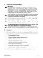
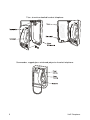
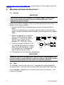
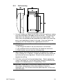
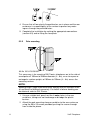
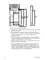
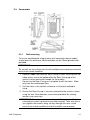
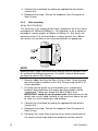
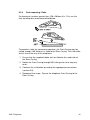
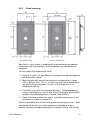
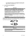
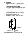
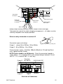
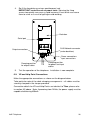
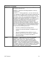
Titan
Commander
Vandal Resistant
Help Point
Installation and User Guide
Rugged VoIP Telephone
Titan, Commander, VR and Help Point models
IMPORTANT
THESE PRODUCTS MUST BE CONFIGURED PRIOR TO
INSTALLATION
PLEASE READ THIS GUIDE FIRST
GAI-TRONICS
A division of Hubbell Ltd.
Doc. No. 502-20-0115-001
Iss 4.
July 2013. (CN37652-001)
CONTENTS
1.
Safety and Care Information ....................................................................... 4
2.
Features ..................................................................................................... 4
3.
Quick Start Guide ....................................................................................... 7
4.
Alternative Configuration Methods.............................................................. 8
5.
Mounting methods and dimensions ............................................................ 9
6.
7.
5.1.
General ........................................................................................ 9
5.2.
Titan ............................................................................................. 9
5.3.
Commander ............................................................................... 14
5.4.
VR and Help Point...................................................................... 17
Connections and Installation .................................................................... 19
6.1.
General ...................................................................................... 19
6.2.
IMPORTANT SAFETY INFORMATION ..................................... 20
6.3.
Emergency Services warning ..................................................... 20
6.4.
Titan Installation ......................................................................... 21
6.5.
Titan Connections ...................................................................... 21
6.6.
Commander Installation ............................................................. 23
6.7.
Commander Connections........................................................... 24
6.8.
VR and Help Point Installation.................................................... 25
6.9.
VR and Help Point Connections ................................................. 26
Cleaning ................................................................................................... 27
7.1.
Normal Cleaning ........................................................................ 27
7.2.
Stainless Steel Push-buttons ..................................................... 27
7.3.
Graffiti......................................................................................... 27
7.4.
Anti-Graffiti Coating .................................................................... 27
8.
Aftercare ................................................................................................... 27
9.
Technical Specifications ........................................................................... 28
VoIP Telephone.
2
3
10.
CE Declaration ......................................................................................... 32
11.
Licensing Notices ..................................................................................... 33
VoIP Telephone.
1.
Safety and Care Information
▲
IMPORTANT:
▲
Please read these instructions thoroughly before starting installation.
These products must be installed by competent personnel familiar
with electrical and network installations.
▲
▲
Refer to safety information is section 6.2 if hazardous voltages (eg
mains) are to be connected to this product.
▲
▲
Take adequate precautions when opening the case or installing. If in
doubt, isolate connections elsewhere before opening.
2.
THIS PRODUCT CAN CONTAIN HAZARDOUS VOLTAGES. IT IS
ESSENTIAL THAT THE WATERPROOF SEAL IS PROPERLY MADE
DURING INSTALLATION, TO ENSURE THAT WATER CANNOT GET
INTO THE ENCLOSURE. THE INGRESS OF WATER CAN CAUSE
ACCESSIBLE PARTS OF THE TELEPHONE TO BECOME LIVE, AND
THEREFORE MUST BE PREVENTED AT ALL COSTS.
Make sure that correctly-sized cable glands are used, and that cables
are securely clamped in the clamps provided. Failure to do so could
result in an unsafe installation.
The spring-loaded door (Titan models only, where fitted) can close
sharply. Take care not to trap fingers etc., during installation and use.
Features
This manual describes the voice over internet protocol (VoIP) versions of the
Titan, Commander, Vandal Resistant (handsfree) and Help Point telephone
ranges. Features include:
•
SIP compatible (RFC3261)
•
Automatic outgoing call diversion (memory list)
•
Weather and vandal resistant
•
Wide operating temperature range
•
Real-time alarm reporting via email or Syslog
•
Power over Ethernet compatible
•
Configurable via web page, serial link or download
•
4 auxiliary inputs, 2 volt-free contact outputs
Models are available with different casing, keypad and handset options.
VoIP Telephone.
4
Titan, aluminium-bodied handset telephone
Commander, rugged glass-reinforced polyester handset telephone:
5
VoIP Telephone.
Vandal Resistant (VR) handsfree telephone:
SPEAKER
FLUSH, 25mm
CALL BUTTON
FRONTPLATE
MICROPHONE
LED
Help Point handsfree telephone:
REAR
ENCLOSURE
SPEAKER
PALM-OPERABLE,
STAINLESS STEEL
CALL BUTTONS
FRONTPLATE
MICROPHONE
LED
VoIP Telephone.
6
3.
Quick Start Guide
IMPORTANT
THESE UNITS MUST BE CONFIGURED BEFORE THEY ARE INSTALLED.
All units have identical settings as factory defaults, so each one must be
individually configured to give it a unique identity on the network. This may
be difficult to do after the units are installed.
The general sequence for set up and use is:
Stage
Comment
1.
Initial network configuration
Essential. Each phone must be set up for the
network prior to installation. Each unit is
usually dedicated to a specific location - make
sure each configured phone is identified ready
for installation. Refer to configuration guide
(available from website).
2.
Change user name and
password
Recommended, to prevent unauthorised
changes to the phone's configuration. Make
sure to record these details securely. Refer to
configuration guide (available from website).
3.
Check for power and
network.
Ensure that a network port is available within
95m of intended installation. Ensure that a
power source is available (either local 24-48V
DC or PoE). Refer to section 9.
4.
Mounting
Physical mounting at the intended location.
Refer to section 5.
5.
Installation
Connections and cabling. Connection to the
network at the intended location. Refer to
section 6.
6.
Final configuration (can also
be done prior to installation)
Setting autodial numbers, etc. Can be done
remotely. Refer to configuration guide
(available from website).
7.
Test
Check that calls can be made successfully
8.
Maintain
Monitor alarms. Set up auto-updates. Refer to
configuration guide (available from website).
7
VoIP Telephone.
The easiest way to get started is to make a network connection to the unit and log
on via a web browser.
The unit is initially set with a static IP address:
IP address
192.168.1.2
It will request a user name and password, the initial factory settings are:
User Name
user
Password
password
The phone’s home page is as shown below, and allows access to all the other
configuration pages. Use the Network IP Settings page to change IP settings
appropriate for the intended network.
Full help is available from
www.gai-tronics.co.uk/voipsupport.htm
A CD containing all manuals, release notes etc., is available from GAI-Tronics on
request.
4.
Alternative Configuration Methods.
There are 3 methods for configuring GAI-Tronics VoIP telephones: • Web pages
• Configuration file
• Command Line interface (CLI)
Web pages (held within the telephone) can be accessed over the network using a
browser such as Internet Explorer™, to view and change settings within a single
unit.
Configuration files are ASCII text files containing configuration options that can be
read and edited by a knowledgeable user using any plain text editor such as
Notepad™. The telephone can automatically download a configuration file from the
network, providing a controlled method of configuring multiple telephones.
The telephone can also be configured using a command line interface, either via the
local serial port or remotely via a TELNET session over the network. The initial
default settings for the serial port are :
Speed:
Data bits:
Stop bts:
Parity
115200
8
1
No
The complete syntax and command structures of configuration files and the CLI are
included in the Configuration guide available from
VoIP Telephone.
8
www.gai-tronics.co.uk/voipsupport.htm (also available on CD on request from GAITronics).
5.
Mounting methods and dimensions
5.1. General
IMPORTANT
Installation details differ between the product ranges –please make
sure you know which product you are installing and refer to the
appropriate sections below.
Before mounting the telephone, check the cable routing and requirements. Fit
gland(s) to the case as follows:
1. Remove the RED blanking plug leaving the other (usually BLACK) in
place.
Only fit a second gland if any external inputs or outputs are being used –
cables for these should be routed through a separate gland to the network
cable.
2. Select the appropriate sized gland:
Use the smaller gland for cables
diameters 4 - 7mm (0.16 – 0.27in).
Use the larger gland for cable
diameters 8 - 13mm (0.3 – 0.5in).
3. From the outside of the case, insert
the selected gland into the threaded
cable entry hole and tighten, so that
its sealing washer is compressed
against the enclosure surface.
4. Proceed with chosen mounting method below
IMPORTANT
Glands are essential to clamp cables and to ensure a weatherproof seal.
It is the installer’s responsibility to make sure they are correctly selected
and fitted. Failure to do so could result in an unsafe installation.
5.2. Titan
As standard, Titan with rear enclosure is supplied with 2 cable glands with
sealing washers, 4 countersunk screws with wall plugs and a 3mm Allen key.
Titan telephones supplied for flush mounting have no rear enclosure – see
section 5.2.3 below.
9
VoIP Telephone.
5.2.1
Wall mounting
1. Using a suitable tool, punch out 4 holes in the rear enclosure, taking
care not to damage or dislodge the plastic bushes. Only four of the
eight holes are required - the outer ones are recommended. The
inner holes are provided to be compatible with older-style mounting
posts, and should be left intact if not used. If the inner holes are
used they must be fitted with the supplied plastic bushes.
WARNING:.An unsafe condition could occur (and your warranty will be
invalidated) if :1. Any fixing hole made in the rear enclosure is left unused.
2. Any additional holes are drilled into the telephone enclosure.
3. Plastic bushes are not used on all fixing holes.
2. Mark the wall with hole centres based on the dimensions shown
(145 x 270mm, 5.7 x 10.63in). If necessary offer the rear enclosure
up to the wall to check alignment. Do not use the enclosure as a
template for drilling.
3. Drill holes in the wall on the marked positions. Select appropriate
screws, wall plugs etc., for the type of wall, bearing in mind that the
weight of the complete phone is around 5kg (11lbs).
IMPORTANT: USE ONLY countersunk-headed fixing screws. Check
that screws seat properly in the plastic bushes to ensure a
watertight seal. Do not use excessive tightening force, as this may
crack the case.
VoIP Telephone.
10
4. Ensure that all four plastic flanged bushes are in place and the rear
enclosure is screwed tightly to the surface to prevent any water
ingress through the punched holes.
5. Complete the installation by making the appropriate connections
(section 6.5) and re-fitting the face plate.
5.2.2
Pole mounting
Kit No 100-02-0208-001
This accessory is for mounting GAI-Tronics telephones on to the side of
round poles of 100mm to 200mm diameter (4 - 8in), or on to square or
rectangular section uprights of 100mm to 150mm (4 – 6in) across the
mounting surface.
NOTE:
Banding straps (large scale worm-drive clamps) are not included in this
kit and must be obtained separately. For details of where banding can
be obtained, refer to GAI-Tronics.
1. Using a suitable tool, punch out the 4 outer holes in the rear
enclosure, taking care not to damage or dislodge the plastic
bushes.
2. Attach the pole mounting clamp assemblies to the rear enclosure
using the M6 x 25 screws provided, pushing the screws through
from inside the phone.
11
VoIP Telephone.
3. Tighten nuts to a torque of 4.5Nm (3.3lb-ft) max.
IMPORTANT: avoid the use of power tools. Spinning the nuts too
quickly can cause a rapid increase in heat which can cause the nuts
to seize as a result of galling or cold-welding.
Note: only use the outer four holes, and ensure that the screws seat
properly in the plastic bushes to avoid water ingress.
4. Ensuring that the glands are at the bottom, pass a proprietary
banding strap round each of the pole mounting clamps and the
support pole. Tighten securely.
5. Continue the installation by making the appropriate connections
(section 6.5) and re-fitting the face plate.
6. Re-tighten the straps firmly and trim off any excess band material.
For security the driving head of the band may also be sawn off.
5.2.3
Flush mounting
Titan telephones supplied for flush mounting have a slightly different
faceplate to those supplied with a rear enclosure – in particular the fixing
holes are in different positions and there are no corner cut-outs (for door
hinges). These models are usually described as “Titan fp” and the
supplied mounting kit contains round-headed screws and no glands.
Note that it is the installer’s responsibility to prevent moisture coming
into contact with the electronics and connections on the back of the
faceplate.
VoIP Telephone.
12
To flush-mount the telephone to a wall:
1. Prepare a recess (at least 50mm, 2in deep) in the wall according to
the dimensions shown.
2. Mark the wall with hole centres based on the dimensions shown
(155 x 326mm, 6.1 x 12.84in). If necessary offer the faceplate up to
the wall to check alignment. Do not use the telephone as a
template for drilling.
3. Drill holes in the wall at the marked positions. Select appropriate
screws, wall plugs etc., for the type of wall, bearing in mind that the
weight of the complete phone is around 1.5kg.
4. Route the cable to within the recess, and make connections to the
telephone as shown in section 6.5.
5. Secure the telephone to the wall taking care not to trap any wires.
The gasket on the rear of the faceplate is intended to make a
weather seal when compressed against a smooth surface. Do not
rely on this gasket to keep water out if mounting directly to rough
surfaces such as brickwork – in these cases use additional sealant
around the edges to ensure a weatherproof seal.
13
VoIP Telephone.
5.3. Commander
5.3.1
Wall mounting
To ensure weatherproof integrity when wall mounted, external cables
should enter the enclosure from the bottom via the 20mm gland entries
provided.
IMPORTANT:
Do not drill any extra holes as this will invalidate your warranty and could
result in an unsafe condition.
1. Remove rubber feet from the Rear Casing if fitted. Ensuring that the
cable entries are at the bottom offer the Rear Casing up to the
vertical surface and mark through the fixing holes.
Do not use the Rear Casing as a template to drill the holes. Work
only from the marked positions.
2. Drill the holes in the vertical surface to suit the best method of
fixing.
3. Ensure the Rear Casing is securely attached to the vertical surface
using the four 7mm diameter screw holes provided. No sealing
washers are necessary.
IMPORTANT: Do not use countersunk headed fixing screws. Only use
round head, socket cap head or pan head screws. Take care not to
over tighten the screws, doing so may damage the case, could
result in an unsafe condition and will invalidate your warranty.
VoIP Telephone.
14
4. Continue the installation by making the appropriate connections
(section 6.5).
5. Reconnect the ringer. Secure the telephone Front Casing to the
Rear Casing.
5.3.2
Pole mounting
Kit No 100-02-0208-001
This accessory is for mounting GAI-Tronics telephones on to the side of
round poles of 100mm to 200mm (4 – 8in) diameter, or on to square or
rectangular section uprights of 100mm to 150mm (4 – 6in) across the
mounting surface. For flat mounting on surfaces greater than 150mm
(6in) across use the desk or wall mounted methods as appropriate.
NOTE:
Banding straps (large scale worm-drive clamps) are not included in this
kit and must be obtained separately. For details of where banding can
be obtained, refer to GAI-Tronics.
1. Remove rubber feet from the Rear Casing if fitted. Attach the pole
mounting clamp assemblies to the Rear Casing using the M6 x 25
screws provided.
2. Ensuring that the glands are at the bottom, pass a proprietary
banding strap round each of the pole mounting clamps and the
support pole. Tighten to a torque of 4.5Nm (3.3lb-ft) max.
IMPORTANT: avoid the use of power tools. Spinning the nuts too
quickly can cause a rapid increase in heat which can cause the nuts
to seize as a result of galling or cold-welding.
3. Continue the installation by making the appropriate connections
(section 6.5).
4. Reconnect the ringer. Secure the telephone Front Casing to the
Rear Casing.
5. Re-tighten the straps firmly and trim off any excess band material.
For security the driving head of the band may also be sawn off.
15
VoIP Telephone.
5.3.3
Desk mounting / Rake
For horizontal surfaces greater than 150 x 280mm (6 x 11in) use the
free-standing desk mounted method below.
To provide a 'rake' for convenient operation, the Front Casing may be
turned through 180° before it is fitted to the Rear Casing. Thus the cable
entries are at the rear of the telephone.
1. Ensure that the supplied rubber feet are fitted to the underside of
the Rear Casing.
2. Rotate the Front Casing through180° taking care not to trap any
wires.
3. Continue the installation by making the appropriate connections
(section 6.5).
4. Reconnect the ringer. Secure the telephone Front Casing to the
Rear Casing.
VoIP Telephone.
16
5.4. VR and Help Point
From a mounting and installation point of view, VR and Help Point products
are identical.
5.4.1
Wall/Pole Mounting
When wall or pole mounted, VR and Help Point units must be fitted
inside a dedicated rear enclosure. The rear enclosure is identical to the
Titan enclosure (although usually without a door). Follow the Titan
mounting information given in sections 5.2.1 (wall mounting) or 5.2.2
(pole mounting).
17
VoIP Telephone.
5.4.2
Flush mounting
Note that it is the installer’s responsibility to prevent moisture coming
into contact with the electronics and connections on the back of the
faceplate.
To flush-mount the telephone to a wall:
1. Prepare a recess (at least 50mm, 2in deep) in the wall according to
the dimensions shown.
2. Mark the wall with hole centres based on the dimensions shown
(166 x 307mm, 6.5 x 12.1in). If necessary offer the faceplate up to
the wall to check alignment. Do not use the telephone as a
template for drilling.
3. Drill holes in the wall at the marked positions. Select appropriate
screws, wall plugs etc., for the type of wall, bearing in mind that the
weight of the complete phone is around 1.5kg (3.3lbs).
4. Route the cable to within the recess, and make connections to the
telephone as shown in section 6.5.
Secure the telephone to the wall taking care not to trap any wires. Note
that the gasket on the rear of the faceplate is intended to make a
weather seal when compressed against a smooth surface. Do not rely
VoIP Telephone.
18
on this gasket to keep water out if mounting directly to rough surfaces
such as brickwork – in these cases use additional sealant around the
edges to ensure a weatherproof seal.
6.
Connections and Installation
6.1. General
IMPORTANT
THIS PRODUCT CAN CONTAIN HAZARDOUS VOLTAGES. IT IS
ESSENTIAL THAT THE WATERPROOF SEAL IS PROPERLY MADE
DURING INSTALLATION, TO ENSURE THAT WATER CANNOT GET
INTO THE ENCLOSURE. THE INGRESS OF WATER CAN CAUSE
ACCESSIBLE PARTS OF THE TELEPHONE TO BECOME LIVE, AND
THEREFORE MUST BE PREVENTED AT ALL COSTS.
All possible measures must be taken to ensure water, fluid or dust
does not contaminate the internal components of the telephone whilst
unpacking, preparing and installing the telephone in inclement weather
conditions or by negligence.
Failure to do so may result in an unsafe condition and will invalidate
your warranty.
Insert each cable through its gland body and tighten the gland nut sufficiently to
clamp the cable, making a seal. Do not over tighten the gland – CAT5 UTP can be
damaged by excess tightening. Ensure sufficient cable is left to allow removal of the
front section of the phone without straining the cable.
IMPORTANT: If only one gland entry is used, the blanking plug fitted to the
second gland position must be left in place.
IMPORTANT
Installation details differ between the product ranges –please make
sure you know which product you are installing and refer to the
appropriate sections below.
19
VoIP Telephone.
6.2. IMPORTANT SAFETY INFORMATION
Please pay particular attention to the following points if hazardous
voltages (>48V) are to be connected to either of the control outputs:
The circuits that the relay contacts are connected to must be of the
same type, i.e. Both mains, both SELV or both TNV. It is not
permissible to mix the types of circuit connected to these relays.
It is acceptable to connect mains circuits in the frequency range 45 to 65
Hz to these relays.
For currents up to 5 Amps, the minimum conductor cross sectional area
2
2
must be 0.75 mm (19awg) for flexible cords, or 1mm (18awg) for other
cables. For currents up to 10 Amps, the minimum conductor cross
2
2
sectional area must be 1 mm (18awg) for flexible cords, or 1.5mm
(16awg) for other cables.
Circuits connected to these relays must be protected against overcurrent and short circuit by a suitable method, for example a fuse or
circuit breaker rated at less than or equal to the relay contact rating.
The use of an isolated supply or an RCD is recommended for these
circuits.
Cables or cords used must be insulated and and have an overall
insulated outer sheath covering both conductors. They must be
appropriately rated and certified. Examples of suitable ratings for PVC
cords are IEC 60227 designation H05 VV-F or H05 VV-F2, or for rubber
insulated cords, IEC 60245 designation H05 RR-F
Extra precautions must be taken for flush-mounted Titan, VR and Help
Point products (where a GAI-Tronics rear enclosure is not used). In this
case it is the installer's responsibility to ensure that the installation is
safe, that there is no possibility of any contact being made to live
terminals, that cables are properly restrained to prevent them becoming
detached, and that there is no possibility of water, dust or other fluids
coming into contact with the rear of the product.
Always ensure that sufficient clearance is maintained between
hazardous voltages and any accessible conductive parts.
If in doubt always use a GAI-Tronics rear enclosure, installed according
to these instructions.
6.3. Emergency Services warning
If, as configured, the telephone cannot make a direct call to the
emergency services, check with your network administrator whether it is
necessary to warn users, and if so provide a suitable warning notice. A
warning label, which can be fixed to the front of the telephone, is
provided.
VoIP Telephone.
20
6.4. Titan Installation
1.
To prepare for installation, open the door (where fitted), then undo the
four retaining screws to remove the faceplate from the rear enclosure. A
3mm Allen key is required.
Caution – take care to support the spring-loaded door whilst open
to prevent it slamming shut and trapping fingers.
2.
The Titan telephone is intended for vertical installation to a wall or pole.
Select the required mounting method (section 5) and mount the rear
enclosure first where applicable.
3.
Route the required cables through glands as appropriate, and make
connections following section 6.5. When fitting mains wiring to this
product that is not wholly run within trunking, it is important that the
strain relief is correctly installed and tested to ensure there will be no
disturbance to the wire terminations. As a minimum the cable must
withstand a pull of 100N (approx 10kg force or 22.5lbf) without visible
movement. If conduit is used, mains cables must be secured elsewhere.
4.
Re-fit the faceplate ensuring a weatherproof seal
5.
Test the operation of the telephone. Installation is now complete.
6.5. Titan Connections
Back-box
Serial port
RJ45 Network connector
(under back-box)
1A-T
Output connections
OP1
OP2
0V
0V
+
48Vdc
IP1 IP2 IP3 IP4
Power connections
Input connections
Clamping position
for output cables
Clamping position
for power and input
cables
Make the appropriate connections as shown on the diagrams below.
21
VoIP Telephone.
1A-T
OP2
0V
+
AUX
IP1 IP2 IP3 IP4
OP1
Connection
to Output 1
0V
Connector Legend
Clamp (on
secondary
insulation)
Connection
to Input 1
AUX 24-48Vdc
Connection
Barrier
Cabling example showing connections to Input 1, Output 1 and aux. DC supply.
Take particular note of the cable clamping arrangements – all cables must be
securely clamped in the clamps provided.
Refer to safety information in section 6.2
Connection types and ratings:
Clamp cables by bending tabs
Output 1 - rating 10A at 250Vac, 10A at 30Vdc
Output 2 - 5A at 250Vac, 1A at 24Vdc
External power supply - 24-48Vdc, 200mA (400mA for VR and Help Point
units if powering from 24Vdc).
NOTE: Earlier models are 48Vdc only. Check the connector legend as
shown above. If it is marked "AUX" it can accept voltages between 24 and
48V DC. If it is marked "48V" it is 48V only.
Output 2
Common
(for inputs)
AUX 24-48V DC
-+
Output 1
12 34
Inputs
Network
End view of Connectors
VoIP Telephone.
22
Control inputs - for connection to voltage free contacts only. Internal pull-up
resistor source current = 300uA. These inputs form part of a SELV circuit and
precautions must be taken to prevent hazardous voltages being applied to
these circuits
LAN connection - RJ45 on Cat5 or Cat5e UTP cable
All other connections - 0.14mm² to 2.5mm² (26 to 14awg) for rigid/solid
cables, 0.14mm² to 1.5mm² (26 to 16awg) for flexible/stranded cable.
6.6. Commander Installation
23
1.
To prepare for installation, undo the three retaining screws shown to
remove the front casing from the rear. The screws are captive in the
front casing; a 5mm Allen key is required. Disconnect the ringer
connector from the circuit board, noting the position and orientation.
2.
The Commander telephone can be installed vertically to a wall or pole,
or used horizontally on a desk. Select the required mounting method
(section 5) and mount the rear casing first where applicable.
3.
Route the required cables through glands as appropriate, and make
connections following section 6.7. When fitting mains wiring to this
product that is not wholly run within trunking, it is important that the
strain relief is correctly installed and tested to ensure there will be no
disturbance to the wire terminations. As a minimum the cable must
withstand a pull of 60N (approx 6kg force or 13.5lbf) without visible
movement. If conduit is used, mains cables must be secured elsewhere.
4.
Reconnect the ringer. Re-secure the telephone Front Casing to the
Rear Casing with the three retaining screws, ensuring a weatherproof
seal.
5.
Test the operation of the telephone. Installation is now complete.
VoIP Telephone.
6.7. Commander Connections
Make the appropriate connections as shown on the diagrams below.
Input connections
Power connections
Clamping position for
input and power cables
Ringer
connector
NC
COM NO
E+
E- M+ M-
LOOP
R+
R-
WARNING!
Ringer
DO NOT DRILL ANY ADDITIONAL
HOLES IN THIS CASE
Serial port
Clamping position for
network cable
RJ45 connector
OP1
OP2
Network cable
(led through this
gland)
Clamping position
for output cables
Output connections
Take particular note of the cable clamping arrangements – all cables must be
securely clamped in the clamps provided.
Connection types and ratings:
Output 1 - rating 10A at 250Vac, 10A at 30Vdc
Output 2 - 5A at 250Vac, 1A at 24Vdc
Refer to safety information in section 6.2
Clamp cables by bending tabs
Clamp
Network cable
Barrier
OP1
OP2
Clamp
Connection to Output 1
Cabling example showing connection to Output 1
VoIP Telephone.
24
Hookswitch
AUX DC supply
Common (for inputs)
Clamp
NC
+
Inputs
1
2
3
4
NO
AUX
E+ E-
M+ M-
LOOP
Handset
R+
R-
Ringer
External power supply – 24-48Vdc, 200mA
NOTE: Earlier models are 48Vdc only. Check the connector legend as
shown above. If it is marked "AUX" it can accept voltages between 24 and
48V DC. If it is marked "48V" it is 48V only.
Control inputs - for connection to voltage free contacts only. Internal pull-up
resistor source current = 300uA. These inputs form part of a SELV circuit and
precautions must be taken to prevent hazardous voltages being applied to
these circuits
LAN connection - RJ45 on Cat5 or Cat5e UTP cable
All other connections - 0.14mm² to 2.5mm² (26 to 14awg) for rigid/solid
cables, 0.14mm² to 1.5mm² (26 to 16awg) for flexible/stranded cable.
6.8. VR and Help Point Installation
25
1.
To prepare for installation, remove the faceplate from the rear enclosure
(if supplied) by undoing the four retaining screws. A 3mm Allen key is
required.
2.
VR and Help Point telephones are intended for vertical installation to a
wall or pole or flush-mounted into a vertical surface. Select the required
mounting method (section 5) and mount the rear enclosure first where
applicable.
3.
Route the required cables through glands as appropriate, and make
connections following section 6.9. When fitting mains wiring to this
product that is not wholly run within trunking, it is important that the
strain relief is correctly installed and tested to ensure there will be no
disturbance to the wire terminations. As a minimum the cable must
withstand a pull of 60N (approx 6kg force or 13.5lbf) without visible
movement. If conduit is used, mains cables must be secured elsewhere.
VoIP Telephone.
4.
Re-fit the faceplate ensuring a weatherproof seal
IMPORTANT: avoid the use of power tools. Spinning the fixing
screws too quickly can cause a rapid increase in heat which can cause
them to seize as a result of galling or cold-welding.
Back-box
Serial port
RJ45 Network connector
(under back-box)
1A-T
Output connections
OP1
OP2
0V
0V
+
48Vdc
IP1 IP2 IP3 IP4
Power connections
Input connections
Clamping position
for output cables
5.
Clamping position
for power and input
cables
Test the operation of the telephone. Installation is now complete.
6.9. VR and Help Point Connections
Make the appropriate connections as shown on the diagram below.
Take particular note of the cable clamping arrangements – all cables must be
securely clamped in the clamps provided.
Connection details for VR and Help Points are identical to Titan, please refer
to section 6.5 above. Note: if powering from 24Vdc, the power supply must be
capable of delivering 400mA.
VoIP Telephone.
26
7.
Cleaning
Recommended cleaning methods are outlined below:
7.1. Normal Cleaning
For normal cleaning we recommend "Virosol", manufactured by Clover
products.
Carefully follow manufacturer's instructions for storage, handling and use.
7.2. Stainless Steel Push-buttons
Stainless steel push-buttons, where fitted, should be cleaned regularly
especially if the Help Point is in a marine environment. The stainless steel
may show signs of discolouration or rust – this will not damage the buttons or
impair their performance but may look unsightly and can be cleaned off using
normal cleaning agents as above. In extreme cases a mild abrasive may be
necessary.
7.3. Graffiti
For graffiti, paint and ink we recommend the use of 3M GR1 graffiti stain
remover.
CAUTION: This is a very aggressive chemical. Pay close attention to the
manufacturer's recommendations for storage, handling and use.
7.4. Anti-Graffiti Coating
Where polyurethane anti-graffiti coating or paint has been specified (as an
option), it can be cleaned using Methylated Spirits or Methyl Isobutyl Ketone.
Other cleaners can be used but should be tested on a small area first
8.
Aftercare
The purchase of your GAI-Tronics product does not end our commitment to
you.
In addition to our warranty obligations, GAI-Tronics are able to offer various
levels of maintenance packages, installation and commissioning packages and
technical support, from ad-hoc repairs to full maintenance contracts.
By choosing GAI-Tronics as your aftercare provider you are ensured of
manufacturer expertise and ISO 9000-certified quality control standards
throughout the life of the product.
We can also supply a full range of accessories including mounting posts,
beacons and high-volume sounders.
Contact GAI-Tronics for details. www.gai-tronics.co.uk
27
VoIP Telephone.
9.
Technical Specifications
Product features
Power supply
Hookswitch
Ringer loudness
Handset
(Titan &
Commander)
Network
Power-over-Ethernet, 802.3af compliant (Class 0) via RJ45,
both method A and method B, or
External power supply: 24-48Vdc, 200mA, except VR and
Help Point models being powered from 24Vdc, which require
400mA.
NOTE: Earlier models are 48Vdc only. Check the
connector legend as shown in section 6.5 or section 6.7.
A separate, isolated supply must be provided for each
telephone.
Voltage range (24V versions): 22-50V
Voltage range (48V versions): 36-56V
Electronic with no external moving parts
80dBA @ 1m
Suitable for inductive coupling to Hearing Aids having
a `T' switch position.
Tested to ETS 300-381
10/100 BaseT Ethernet RJ45, Cat5 or Cat5e UTP
Static IP provisioning or DHCP
STUN client (NAT traversal)
Call Control
Signalling
SIP (RFC3261 compliant)
External inputs
4 auxilliary inputs, volt free, (internal pull-up resistor source
current = 300uA)
External outputs
Output 1 - rating 10A at 250Vac, 10A at 30Vdc
Output 2 - 5A at 250Vac, 1A at 24Vdc
Loose routing
REFER TO SAFETY INFORMATION IN SECTION 6.2
Codecs & Audio
VoIP Telephone.
G.711 A-Law
G.711 µ-Law
G.722
G.729
G.723.1 MP-MLQ
G.723.1 ACELP
Codec preference sequence
DTMF in-band / out-of-band (RFC2833)
Configurable comfort tones (to emulate national tones)
28
Product features
Configuration
Embedded web server
Embedded Telnet server
Configuration file download
Direct serial connection (9 way D type female connector)
Command line interface
SNTP with timezone and daylight saving
Automatic updating via TFTP
Password protection
Monitoring and
Real-time over TCP/IP Syslog application or email.
Reporting
Embedded SMTP client
Automatic fault reporting
Handset integrity monitoring
Call Diversion
Configurable call lists (max 20 entries)
Numbers or URIs (with comfort tones)
Divert to next in list if the call fails
Environmental limits
Temperature:
Operating: -20ºC to +60ºC (-4°F to 140°F)
Storing: -40ºC to +70ºC (-40°F to 158°F)
Relative Humidity Up to 95% (non-condensing)
Ingress
IP65. (Titan with door closed IP66) to EN60529:1992 –
Protection
Degrees of protection provided by enclosures.
Physical characteristics
Casing material
Handset Material
Weight
Dimensions
29
Aluminium (Titan, VR and Help Point)
Glass reinforced polyester (Commander)
Cycoloy (2800) with stainless steel or polyester curled cord.
3 –5kg (2.2 – 11lbs) depending on option.
Dependant on model and variant. See 5.2 (Titan), 5.3
(Commander) or 5.4 (VR or Help Point).
VoIP Telephone.
Compliance to standards
EMC
EN55022 – Information technology equipment. Radio
disturbance characteristics.
EN55024 – Information technology equipment. Immunity
characteristics.
EN 50121-4 - Railway applications, emission and immunity
This equipment has been tested and found to comply with the
limits for a Class B digital device, pursuant to part 15 of the
FCC Rules. These limits are designed to provide reasonable
protection against harmful interference in a residential
installation. This equipment generates, uses and can radiate
radio frequency energy and, if not installed and used in
accordance with the instructions, may cause harmful
interference to radio communications. However, there is no
guarantee that interference to radio or television reception,
which can be determined by turning the equipment off and on,
the user is encouraged to try to correct the interference by
one or more of the following measures:
Safety
VoIP Telephone.
•
Re-orient or relocate the receiving antenna.
•
Increase the separation between the equipment and
receiver.
•
Connect the equipment into an outlet on a circuit
different from that to which the receiver is connected.
•
Consult the dealer or an experienced radio/TV
technician for help
EN60950-1 – Specification for information technology
equipment, including electrical business equipment.
BS6317:1992 (Clause 13.9) - Specification for simple
telephones for connection to public switched telephone
networks run by certain public telecommunication operators.
EN50371 - Generic standard to demonstrate the compliance
of low power electronic and electrical apparatus with the basic
restrictions related to human exposure to electromagnetic
fields (10 MHz - 300 GHz). General public.
30
European
Directives
2004/108/EC – EMC Directive
2006/95/EC – Low Volltage Directive (LVD)
2011/65/EC - Restriction of the use of certain
hazardous substances in electrical and
electronic equipment (recast) (RoHS 2)
Directive
2002/96/EC - Waste Electrical and Electronic Equipment
(WEEE) Directive
Recycling
Information
The symbol shown here and on the product means
that the product is classed as Electrical or Electronic
Equipment and should not be disposed with other
household or commercial waste at the end of its
working life.
The Waste of Electrical and Electronic Equipment
(WEEE) Directive has been put in place to recycle
products using best available recovery and recycling
techniques to minimise the impact on the
environment, treat any hazardous substances and
avoid the increasing landfill.
Business users should contact their suppliers and
check the terms and conditions of the purchase
contract and ensure that this product is not mixed
with other commercial waste for disposal.
31
VoIP Telephone.
10. CE Declaration
VoIP Telephone.
32
11. Licensing Notices
The firmware in GAI-Tronics VoIP products contains modules subject to
licensing and copyright as follows:
Module
License
u-boot
Linux kernel
Busybox
Opal/PWLib
Modutils
MTD
NTP
GPL V2
GPL V2
GPL V2
Mozilla Public License V1.1
GPL V2
GPL V2
David L. Mills Copyright Notice
These licence and copyright notices are available in full from our website at
www.gai-tronics.co.uk/voipsupport.htm
33
VoIP Telephone.
VoIP Telephone.
34
35
VoIP Telephone.
GAI-TRONICS
A division of Hubbell Ltd.
Brunel Drive, Stretton Park
Burton on Trent, DE13 0BZ
England
Tel: 01283 500500, Fax: 01283 500400
www.gai-tronics.co.uk
The policy of GAI-Tronics is one of continuous improvement, therefore the Company
reserves the right to change specifications without notice
VoIP Telephone.
36