1
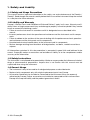
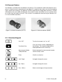
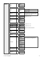
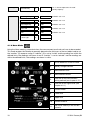
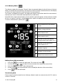
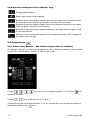
Operating Instructions
Thickness Gauge
Made in Switzerland
Table of contents
1. Safety and Liability
3
2. Tutorial
4
3. Getting Started
3.1 Overview
3.2 Connect Probes
3.3 Overview Keypad
3.4 First Steps before Measuring
5
5
6
6
7
4. Use of the Instrument
4.1 The Different Measuring Modes
4.1.1 Overview of Settings / Menu Structures
4.1.2 Norm Mode
4.1.3 Memory Mode
4.1.4 A-Scan Mode
4.2 Pictograms
4.2.1 Signal Strength Indicators and Measurement Method
4.2.2 Operation Pictograms A-Scan
4.3 Setup-Screen
4.3.1 Create a New Material / Edit a Material
4.3.2 Calibration on known Material / Determinate the US velocity
4.3.3 Overview of Different Setup-Items
8
8
8
10
11
12
13
13
14
14
14
15
15
5. Velocity of Longitudinal Ultrasonic Waves
16
6. Zonolink
16
7. Technical Specifications
18
8. Part Numbers and Accessories
19
9. Maintenance and Support
19
2
© 2014 Proceq SA
1. Safety and Liability
1.1 Safety and Usage Precautions
This manual contains important information on the safety, use and maintenance of the Zonotip /
Zonotip+. Read through the manual carefully before the first use of the instrument. Keep the manual
in a safe place for future reference.
1.2 Liability and Warranty
Proceq’s “General Terms and Conditions of Sale and Delivery” apply in all cases. Warranty and liability claims arising from personal injury and damage to property cannot be upheld if they are due
to one or more of the following causes:
• Failure to use the instrument in accordance with its designated use as described in this
manual.
• Incorrect performance check for operation and maintenance of the instrument and its components.
• Failure to adhere to the sections of the manual dealing with the performance check, operation
and maintenance of the instrument and its components.
• Unauthorized structural modifications to the instrument and its components.
• Serious damage resulting from the effects of foreign bodies, accidents, vandalism and force
majeure.
All information contained in this documentation is presented in good faith and believed to be
correct. Proceq SA makes no warranties and excludes all liability as to the completeness and/or
accuracy of the information.
1.3 Safety Instructions
The instrument is not allowed to be operated by children or anyone under the influence of alcohol,
drugs or pharmaceutical preparations. Anyone who is not familiar with this manual must be
supervised when using the instrument.
1.4 Correct Usage
• The instrument is only to be used for its designated purpose as describe herein.
• Replace faulty components only with original replacement parts from Proceq.
• Accessories should only be installed or connected to the instrument if they are expressly
authorized by Proceq. If other accessories are installed or connected to the instrument then
Proceq will accept no liability and the product guarantee is forfeit.
© 2014 Proceq SA
3
2. Tutorial
The Zonotip / Zonotip+ is designed to measure the thicknesses of ferrous and non-ferrous metals
as well as products made of plastics and other materials with a low ultrasonic attenuation. It measures the double traverse of an ultrasonic pulse through the object under test from one surface to
the other (see figure 1). This value is then converted into the product thickness value.
Thickness h =
c ⋅ t0
, c: speed of sound
2
Transducer
n x t0
2 x t0
t0
h
Object under test
E1
E2
E1
E2
En
t
Figure 1: Determining the thickness of an object by means of ultrasound pulse echo technique
The probe has a sharp radiation directivity and ultrasound receiving pattern, therefore, the product
thickness is determined directly under the converter installation place. If the material surface opposite to the one on which the probe is installed, has cavities, the US pulses will be reflected from
them, and the thickness is determined as the shortest distance from the external surface to these
cavities.
The Zonolink Software, included in the package, allows downloading the data measured by the
Zonotip / Zonotip+ using any PC. Communication with the computer is provided through a USB
port.
Practical Advice for Measuring
To receive the maximal measurement accuracy, make sure that the probe, the calibration sample
and the test object have roughly the same temperature. If the measured velocity of the material
differs from the actual velocity, revise the velocity manually or perform a calibration.
The measurement accuracy directly depends on the accuracy of the velocity setting. For a precise
measurement, take a sample of the same material as the test object and set the velocity according
to it. For this procedure, use the same US converter as for the actual measurement. If possible, use
a plane-parallel sample with smooth surface for the test measurement.
4
© 2014 Proceq SA
3. Getting Started
3.1 Overview
Ports for transducers
Functional keys
Navigation keys
Zeroing sample / test plate
USB Port
Figure 2: The Zonotip instrument
Figure 3: Connection of the 4.0 MHz
transducer. Make sure the red cable is
connected to the port with the red dot.
© 2014 Proceq SA
Figure 4: Connection of the 2.5 MHz transducer
5
3.2 Connect Probes
The Zonotip is available with two different transducers: The standard 4.0 MHz dual-element transducer is meant for most measurements (see figure 5). It requires two cables, one for the outgoing
signal, one for the incoming. The optional 2.5 MHz single-element integrated transducer is smaller
and requires only one cable (see figure 6). This makes it more convenient to use in smaller areas
or in areas that are harder to access. The 2.5 MHz is included when purchasing the Zonotip+ unit.
It is also available separately.
Figure 5: 4.0 MHz transducer (D1771)
Figure 6: 2.5 MHz transducer (S3567)
3.3 Overview Keypad
6
ON / OFF
Turn the instrument “on” or “off”.
Functional Key
Carry out various actions depending on
the settings. The respective operation is
displayed above each of the keys.
Measurement Mode
/ Setup Screen
Switch between the measurement modes
and the setup screen.
Enter
Confirm a selection.
Left / Right
Navigate through the menu.
Up / Down
Navigate through the menu.
Plus / Minus
Select and change active parameters.
© 2014 Proceq SA
3.4 First steps before measuring
After connecting the desired probe, turn on the instrument.
Click
to enter the setup screen (see figure 7).
Figure 7: Setup-Screen
• Select the desired mode - Norm, Memory, A-Scan (Zonotip+ only). The different modes are
explained in chapter 4.1.
• Select the probe which you have connected. A text will appear on the screen. Please
follow these instructions. This process is needed to calibrate the instrument before the first
measurement.
• Please put a little coupling paste onto the built-in zeroing sample (test plate) of the Zonotip
(see figure 2). The thickness of the zeroing sample is 5 mm.
• Select the material you are about to test.
© 2014 Proceq SA
7
4. Use of the Instrument
4.1 The Different Measuring Modes
4.1.1 Overview of Settings / Menu Structures
The Zonotip / Zonotip+ features different measuring modes that can be set in the Setup-Screen:
the Norm mode, the Memory mode and the A-Scan mode (Zonotip+ only).
Measuring Mode
Memory
Norm
A-Scan
Mode
1
Mode
1
Mode
1
Probe 2
Probe 2
Probe 2
Material 3
Material 3
Material 3
Calibrating on
4
Calibrating on
4
Calibrating on
4
Monitor 5
Monitor 5
Discrete 8
Limit: beginning 6
Limit: beginning 6
Scan beginning 15
Limit: end 7
Limit: end 7
Scan end Discrete 8
Discrete
8
Gate: beginning 17
Sound 9
Clear Memory
16
14
Gate: end
18
9
Gain
19
20
Vibration 10
Sound Language 11
Vibration 10
A-Scan type
Measuring units 12
Language 11
Sound Brightness Measuring units 12
Vibration 10
Brightness Language 11
13
13
9
Measuring units 12
Brightness13
8
© 2014 Proceq SA
All Modes
Norm
Mode
1
Memory
A-Scan
Test
Probe
2
Material
3
Calibrating on
4
Monitor
5
Open
D1771 4.0 MHz
S3567 2.5 MHz
Open
New, Aluminium, Gold, Brass, Copper,
Ice, Polyethylene, Lead, Silver, Steel,
Plexiglass, Glass, Titan
Run
for details see 4.3.2
Edit
Inside
Off
Outside
Limit: beginning
6
Edit
for details see 4.3.2
Limit: end
7
Edit
for details see 4.3.2
Discrete
8
0.1
Select the number of decimals
Sound
9
Vibration
10
0.01
On
Off
On
Off
English
German
to change the language, please press
the functional keys multiple times.
French
Language
11
Italian
Portuguese
Spanish
Chinese
Russian
Measuring units
12
Brightness
13
© 2014 Proceq SA
mm
inch
+
-
9
Memory
Clear Memory
14
Run
The % amount represents the used
memory capacity
A-Scan
Scan beginning
15
Edit
for details see 4.3.2
Scan end
16
Edit
for details see 4.3.2
Gate: beginning
17
Edit
for details see 4.3.2
Gate: end
18
Edit
for details see 4.3.2
Gain
19
Edit
for details see 4.3.2
A-Scan type
20
Filled
Empty
4.1.2 Norm Mode
Using the Norm mode is convenient when the measurement results do not have to be recorded.
This mode enables the Zonotip to promptly determine the thickness of the test object and to set
the “monitor” (5) response range. If “monitor” (5) is set to “inside” and the readings are within the
defined limits, the readings are shown in red. If “monitor” is set to “outside” and the readings are
within the defined limits, the readings are shown in white.
10
1.
Active bookmark of Norm mode
2.
Battery charge indicator
3.
Measurement units
4.
Measurement results
5.
Indicator of the measurement
taking method (see chapter 4.2.1)
6.
Indicator of the signal level (see
chapter 4.2.1)
7.
Current Probe
8.
Lower limit
9.
Upper limit
10.
Current material
11.
US waves velocity in the current
material
© 2014 Proceq SA
4.1.3 Memory Mode
The Memory mode of the Zonotip / Zonotip+ allows to promptly determine the thickness of the test
object, to record the measurement in the memory of the instrument, to browse them on the display
as well as to correct the entries and to conduct re-measurements.
The screen is divided into two parts: the upper part displays information about the measurement,
the lower part shows information about previously saved results.
Up to 500 cells (single measurements) can be stored in up to 100 groups. If the maximum number
of cells in a group is reached, a related information caption will appear on the instrument screen.
To store a measurement, please press
.
1.
Active bookmark of the Memory
mode
2.
Battery charge indicator
3.
Measurement units
4.
Measurement result
5.
Indicator of the measurement
taking method (see chapter 4.2.1)
6.
Indicator of the signal level
(see chapter 4.2.1)
7.
Number of group
8.
Number of measurement
9.
Stored measurement results
Editing Stored Measurements
1.
Press the
2.
Use the keys to
3.
Press the
4.
By pressing
5.
Press
key to enter the edit mode. The screen will show
.
to select the measurement that needs to be overwritten.
key to start a new measurement.
, the measured data will be stored (the old data will be overwritten).
to exit the edit mode.
Transferring data
Please note that device needs to be in Memory Mode in order to communicate with PC, refer to
section 6. Zonolink
© 2014 Proceq SA
11
4.1.4 A-Scan Mode (Zonotip+ only)
The A-Scan mode allows excluding measurement inaccuracies, caused by e.g. flaws or cracks in
the test object. The signal is visualized on the display as an A-Scan, which allows a more indepth
analysis of the reading.
The A-Scan mode features the following measurement options:
• thickness of a test object even if it contains flaws or cracks
• general flaw and crack detection
• bond quality of layered materials, including delamination detection
• thickness of layered materials
It is also possible to zoom in on an arbitrary location of the A-Scan in order to interpret the measurements better. Furthermore, the horizontal and vertical position as well as the length of the gate
(red horizontal bar) can be adjusted. The gate feature is especially useful for situations where
several echos appear in the A-Scan. Therefore, the gate must be moved to the echo that needs
to be evaluated.
The screen is divided into two parts: the upper part shows the signal, the lower part displays the
numerical values of the parameters and the operation pictograms (see chapter 4.2.2).
The results of the A-Scan measurement are saved at the end of the last used measurement group.
The latter is created in the Memory mode (see chapter 4.1.3). To view the saved A-Scans, switch to
the Memory mode. The saved A-Scans have the
symbol to the left of the test results.
i
12
When returning to the A-Scan mode, the graphic image of the A-Scan will be lost.
1.
Active bookmark of A-Scan
mode
2.
Battery charge indicator
3.
Measurement units
4.
Measurement results
5.
A-Scan signal
6.
Gate
7.
Scan beginning
8.
Scan end
9.
Gain
10.
Operation pictograms
(see chapter 4.2.2)
© 2014 Proceq SA
Using the Keys in the Active mode
Operation Pictogram
Key
Purpose
Change of gate length
Vertical position of the gate
Horizontal position of the gate
Zoom in on the A-Scan
Set the signal gain in decibel
Horizontal scrolling of the signal on the screen
Set the signal gain in decibel
4.2 Pictograms
4.2.1 Signal Strength Indicators and Measurement Method (Norm Mode and
Memory Mode only)
Signal level is maximal
Signal level is average
Signal level is minimal
No signal
No measurements
Measurement using the ACF method (see chapter 4.2.2)
Measurement using the threshold method (see chapter 4.2.2)
Overwrite mode (see chapter 4.1.3)
© 2014 Proceq SA
13
4.2.2 Operation Pictograms A-Scan (Zonotip+ only)
Change gate parameters
Select signal section to be displayed
Selection of the measurement method: the instant the signal within the gate exceeds
the threshold (vertical position of the gate) is used for the measurement.
Selection of the measurement method: the distance between the peaks of two signals
within the gate is used for the measurement.
Selection of the measurement method: the peak of the signal within the gate is used
for the measurement.
Selection of the measurement method: Auto Correlation Function (ACF) is applied to
the signals within the gate.
4.3 Setup-Screen
4.3.1 Create a New Material / Edit a Material (Applicable for all Modes)
The Zonotip / Zonotip+ can store up to 64 different materials. Enter the “Material” menu to create
or edit a new material. Select “Create” or “Edit” on the screen.
Use the
keys to scroll in the table of symbols (“1”). Press the
key
to choose a symbol.
Use the
keys to edit the lines (“2” and “3”).
To jump from the left to the right box (from “2” to “3”), position the cursor on the first position of
the left box and press the
key.
14
© 2014 Proceq SA
4.3.2 Calibration on known Material / Determinate the US velocity
To determine the velocity of an US wave in a material with a known thickness, use the “Calibrating
on” function in the setup screen.
Enter the thickness of the sample with “Edit” and start the calibration process by pressing “Run”.
The sample thickness should be within 2.0 - 80.0mm (0.078 - 3.15 inch).
Once the data acquisition is finished, the velocity and material can be saved and added to the
database of the instrument (see 4.3.1.).
4.3.3 Overview of Different Setup-Items
Calibration On
4
All Modes
Designed for determining the velocity
of an US wave in a material with a
known thickness
2.0 - 80.0 mm
(0.078 - 3.15 inch)
Monitor
5
All Modes
Set response conditions for color,
sound or vibration alarm
• Inside: results are within the
set interval
• Outside: results are not in
the set interval
• Off: monitor is switched off
Limit: beginning
6
All Modes
Set the lower limit of the “monitor”
0 - 150 mm (0 - 5.9 inch)
Limit: end
7
All Modes
Set the upper limit of the “monitor”
1 - 300 mm (0 - 11.8 inch)
Clear Memory
14
Memory
Erasing the measurement results
Scan beginning
15
A-Scan
Set the beginning of the reflection
area on the screen
0 - 150 mm (0-5.9 inch)
Scan end
16
A-Scan
Set the end of the reflection area on
the screen
5 - 300 mm (0.2 - 11.8 inch)
Gate: beginning
17
A-Scan
Set lower limit
0 - 150 mm (0 -5.9 inch)
Gate: end
18
A-Scan
Set upper limit
1 - 300 mm (0 - 11.8 inch)
Gain
19
A-Scan
Set the amplification of the instrument
inlet path
0 - 80 dB
Type of A-Scan
20
A-Scan
Selection of the signal reflection type
• Fill: reflected in the filled
type
• Outline: reflected in form of
an outline
© 2014 Proceq SA
15
5. Velocity of Longitudinal Ultrasonic Waves
Material
Velocity [m/s]
Material
Velocity [m/s]
Material
Velocity [m/s]
Chrome
6845
Copper
4700
Concretes
2000 - 5400
Zinc
4170
Molybdenum
6290
Gabbro 38
6320
Basalt
5930
Aluminum
6260
Plaster stone
4790
Vanadium
6000
Ebonite
2400
Foliated granite
7870
Bismuth
2180
Osmium
5478
Granite
4450
Tungsten
5460
(Phosphor) bronze
3530
Diabase 85
5800
Iron
5850
Limestone
6130
Dolomite
4450
Gold
3240
Ceramized glass
6740
Fused quartz
5930
Constantan
5240
Steel 20
6060
Plexiglas
2670
Brass
4430
Steel 15
5400
Polystyrene
2350
Capron
2640
Steel 40
5600
Rubber
1480
Ice
3980
Steel 70
5960
Mica
7760
Manganine
4660
Steel 35
5680
Organic glass
2550
Marble
6150
Tantalum
4235
Silicate glass
5500
Silver
3600
Manganese
5561
Teflon
1350
Lead
2160
Magnesium
5790
Steel St3
5930
Tin
3320
Cast iron
3500 - 5600
Textolite
2920
Nickel
5630
Labradorite 44
5450
Porcelain
5340
6. Zonolink
Control Panel
If this icon is in color - there is a connection to the instrument.
If this icon is in greyscale - there is no connection to the instrument.
If there is a connection, the process of data receiving from the instrument can be launched.
saving the data to the PC.
request the online help.
request the information about the application.
Loading the data
• Turn on the thickness gauge.
• Set the device to Memory Mode.
• Connect the thickness gauge to the PC using a USB cable.
• Press the button
(in color).
i
16
Please note that the device is in the Memory Mode; otherwise the device will not
connect to the PC, enabling you to transfer your data.
© 2014 Proceq SA
• The process of data receiving will be launched.
• If the data is transferred successfully, the message “The data from the instrument was fully
received” will appear, and the data will be displayed.

Saving of the received data on the PC
• Press the button
.
• In the window «Save as» name the file and indicate the path for saving.
By default, the software will save the data to the folder where the application is installed. However,
the user can select any folder to save the data in. The default name of the file will have the format
«resultsX», where X is an index number. The index number is generated automatically from the
numbers that are missing in the selected folder. For instance, if there are files «results25» and
«results27» in the folder, the software will advice to save the file with the name «results26».
However, the user can set any name for the data file.
The software will save the files in the *.csv format, which can then be opened in programs such as
Excel or Notepad.

Shutdown
Press the button

If the changes were not saved, the software will warn about that.
© 2014 Proceq SA
17
To save the data, press «Yes». The software will open the window for data saving.
To exit the software without saving the changes press «No».
To return to the application press «Cancel».
7. Technical Specifications
Instrument
Operating temperature
-20 °C to 50 °C (-4 °F to 122 °F)
Humidity
up to 85% RH with a temperature of 25 °C (77 °F)
Battery operation period
9h
Power
built-in LiPol accumulator
Operation supply voltage
3.7 V
Dimension
157 x 70x 23 mm (6.1 x 2.7 x 0.9 inch)
Weight
250 g
Display type
TFT
Permissible surface roughness
Rz160 / N12 / Ra = 50 µm
Minimum curvature radius
10 mm (0.4 inch)
Ultrasonic velocity range
from 1000 to 9999 m/s
Data memory
100 groups each max. 500 measurements
Interface type
USB
Thickness resolution
IP Classification
< 99.99 mm: 0.01 mm
> 100.0 mm: 0.1 mm
IP52
Transducer
Type
Dual-element
Single-element
Frequency
4.0 MHz
2.5 MHz
Measurement range (steel)
0.7 - 300 mm
0.7 - 300 mm
Diameter of ultrasonic element
16 mm (0.6 inch)
10 mm (0.4 inch)
Connector type
LEMO type 00.250
LEMO type 00.250
45 x ∅23 mm (1.8 x ∅0.9 inch)
24 x ∅16 mm (0.9 x ∅0.6 inch)
(∅18.5 at the connector)
23 g
16 g
Size
Weight
Standards and Regulations Applied
• ASTM E 797
• EN 15317
18
© 2014 Proceq SA
8. Part Numbers and Accessories
8.1 Units
Part No.
Description
790 10 000
Zonotip unit consisting of: Indicating device with calibration sample, transducer 4.0 MHz,
transducer cable 2pol 1.2 m, couplant, battery charger with USB cable, carrying strap, data
carrier with software, documentation, protective pouch, carrying case
790 20 000
Zonotip+ unit consisting of: Indicating device with calibration sample, transducer 4.0 MHz,
transducer cable 2pol 1.2 m, transducer 2.5 MHz, transducer cable 1pol 1.2 m, couplant,
battery charger with USB cable, carrying strap, data carrier with software, documentation,
protective pouch, carring case
8.2 Parts and Accessories
790 11 001
D1771 Ultrasonic Transducer 4.0 MHz
790 12 001
S3567 Ultrasonic Transducer 2.5 MHz
710 10 031
Ultrasound couplant, 250 ml
790 80 001
Step Test Block (inches)
790 80 002
Step Test Block (mm)
9. Maintenance and Support
9.1 Support Concept
Proceq is committed to providing a complete support service for this instrument. It is recommended that the user registers the product on the www.proceq.com to obtain valuable information
on available updates and other useful information.
9.2 Standard Warranty and Extended Warranty
The standard warranty covers the electronic portion of the instrument for 24 month and the mechanical portion of the instrument for 6 month. An extended warranty for one, two or three years for
the electronic portion of the instrument may be purchased up to 90 days of purchase.
© 2014 Proceq SA
19
Proceq Europe
Ringstrasse 2
CH-8603 Schwerzenbach
Phone +41-43-355 38 00
Fax
+41-43-355 38 12
[email protected]
Proceq UK Ltd.
Bedford i-lab, Priory Business Park
Stannard Way
Bedford MK44 3RZ
United Kingdom
Phone +44-12-3483-4515
[email protected]
Proceq USA, Inc.
117 Corporation Drive
Aliquippa, PA 15001
Phone+1-724-512-0330
Fax+1-724-512-0331
[email protected]
Proceq Asia Pte Ltd
12 New Industrial Road
#02-02A Morningstar Centre
Singapore 536202
Phone+65-6382-3966
Fax+65-6382-3307
[email protected]
Proceq Rus LLC
Ul.Optikov 4
korp.2, lit. A, Office 410
197374 St. Petersburg
Russia
Phone/Fax + 7 812 448 35 00
[email protected]
Proceq Middle East
P. O. Box: 8365
SAIF Zone, Sharjah
U.A.E
Phone +97165578505
Fax +97165578606
[email protected]
Proceq SAO Ltd.
South American Operations
Alameda Jaú, 1905, cj 54
Jardim Paulista, São Paulo
Brasil Cep. 01420-007
Phone +55 11 3083 38 89
[email protected]
Proceq Trading (Shanghai) Co.
Unit B, 19th Floor
Five Continent International Mansion, No. 807
Zhao Jia Bang Road
Shanghai 200032
Phone +86 21 6317 7479
Fax
+86 21 6317 5015
[email protected]
www.proceq.com
Subject to change without notice.
Copyright © 2014 by Proceq SA, Schwerzenbach
Part number: 820 790 01 E
Made in Switzerland