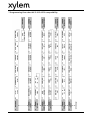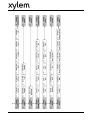
1
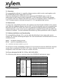
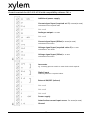
Set-up and programming
guide
HV 2.015-4.220
software
for compatibility to
HV 2.1-3.22
V 2012/05A-C01.4
771079512
Manual C01.4 for HV 2.015-4.220
ENGLISH
Index
1 Important safety instructions ...................................................................................2
2 General information .................................................................................................5
2.1 Overview ..........................................................................................................5
2.2 Restrictions.......................................................................................................5
2.3 Software definition and functionality .............................................................5
2.4 Cross reference list HV 2.1-3.22 vs. HV 2.015-4.220........................................5
3 Technical Data...........................................................................................................6
4 Preparing the HV for compatibility function ...........................................................6
4.1 Control card I/O’s .............................................................................................7
4.2 Control terminals .............................................................................................7
4.3 Comparison between HV 2.1-3.45 and HV 2.015-4.220 compatibility ...........8
5 Programming ..........................................................................................................13
5.1 Display – control panel of the HV 2.015–4.220 .............................................13
5.2 Start up guide ................................................................................................14
5.3 System and application specific parameter settings.....................................16
6 Failure messages .....................................................................................................17
7 Programming flow chart HV 2.015-4.220 compatibility ........................................18
8 Programming flow chart HV 2.1–3.45 vs. HV 2.015–4.220 compatibility..............20
Follow the pump operating and maintenance instructions
We reserve the right to alter specifications
1
1 Important safety instructions
Read and follow the operating and safety instructions carefully
before starting operations!
All modifications must be done by qualified technicians!
Warning that failure to observe the precaution may cause electric shock
Warning that failure to observe the precaution may cause personal injury or
damage to property.
In addition to these operating instructions please pay attention to universal safety
and accident prevention regulations.
Basically the HYDROVAR must be disconnected from the power supply before any work can
be carried out on the electrical or mechanical part of the system.
Installation, maintenance and repair work may be carried out only by trained, skilled and
qualified personnel.
Unauthorized modification or changes to the system make all guarantees null and void.
During operation, the motor can be stopped by opening a digital input or manual
operation whereby the HYDROVAR and the motor remain under voltage. For safety
reasons, the HYDROVAR has to be disconnected from the power supply when carrying out
work on the machinery.
When the HYDROVAR is connected to the power supply, the components of
the power unit as well as certain components of the control unit are
connected directly to the mains.
Touching these components seriously endangers life!
Before removing the HYDROVAR cover the system must be disconnected from
the power supply. After switching off the power supply wait
at least 5 minutes before starting work on or in the HYDROVAR (the
capacitors in the intermediate circuit are discharged by the internal discharge
resistors).
Voltages of up to 800 volts are possible (in case of error these also can be
higher)
2
All work, carried out on the HYDROVAR, may only be performed by
qualified and authorized staff.
Furthermore, take care not to short circuit the neighbouring
components when connecting the external control wires. All cable ends which
are not in use have to be isolated.
The HYDROVAR contains electronic safety devices which switch off the control
element in the event of a fault, whereby the motor has zero current but
remains energised and comes to a halt. The motor can also be halted by
mechanical blocking. If it is switched off electronically the motor is current
less from the mains voltage through the electronics of the HYDROVAR but is
not potential-free in the circuit.
In addition voltage fluctuations, especially power failures can cause the
system to switch itself off.
Repair of faults can cause the motor to start up again automatically!
The system may only be put into operation when it has been grounded.
In addition to that, equipotential bonding of all conductive pipes must be
ensured.
Please consider local installation standards!
High voltage tests of the HYDROVAR or the motor may damage the
electronic components! Hence bridge the in- and outgoing
terminals L1 - L2 - L3 / U-V-W before.
To avoid incorrect metering by capacitors incorporated in the electronic
part isolate the motor from the HYDROVAR.
The operating instructions must be read, understood and
followed by the operating personnel. We point out that we
accept no liability for damage and operating disorders
which are the result of non-compliance with the operating
instructions.
3
Transport, handling, storage, disposal:
•
•
•
Check the HYDROVAR immediately after delivery/receipt for damage or missing parts
The HYDROVAR unit must be transported carefully.
Avoid serious impacts
NOTICE!
Dispose of all packing materials and the HYDROVAR unit in accordance with
local regulations. For more detailed information about the recycling of this
product, please contact your local authority, your waste disposal service
provider or the outlet where you purchased the product.
CAUTION!
Lifting aids (stacker, crane, crane mounting device, lifting blocks, sling
ropes, etc.) must be suitable to handle the weight of the HYDROVAR.
CAUTION!
WARNING!
It is not allowed to carry the HYDROVAR around by using the connected
cables.
Do not damage the cable during transport (do not squeeze, bend or drag).
The cable ends must be kept dry.
•
•
•
Do not stand underneath suspended loads
Take note of the general regulations on prevention of accidents
The HYDROVAR must be secured against tipping over and slipping until
it has been fixed in its final location.
4
2 General information
2.1 Overview
The compatibility software is a specific software version which can be used together with
the HYDROVAR product range HV2.015-4.220.
It has been developed to enable the above mentioned HYDROVAR types to be full
replacement to the former product range HV2.1-3.22 especially in multi pump systems.
I.e. together with this software the HV2.015-4.220 can completely replace a failed HV2.13.22 or simply extend an already existing HV2.1-3.22 equipped pump system.
2.2 Restrictions
To ensure the compatibility function, this software must be already installed on the control
card. With the standard software version (V01.x) this functionality can not be provided and
therefore the HV2.015-4.220 units must be prepared accordingly (either by installing the
software directly on the control card or replacing the complete control with one where the
software is installed – for more detailed information reg. these possibilities refer to page 6).
2.3 Software definition and functionality
The compatibility software C01.x can be easily identified by its item name and version
number. Pls. find the following description for clear identification and differentiation to the
standard version.
V01.x1 – standard software version
C01.x1 – specific compatibility version
1
(x)… stands for the release number, e.g. C01.4
The functions of the compatibility software C01.x are based on the HV VOG120x2 software
version that is standard on all HV2.1-3.22 units. However the parameter structure and
navigation is the same than on the V01.x menu structure.
2.4 Cross reference list HV 2.1-3.22 vs. HV 2.015-4.220
The following table gives an overview about the HYDROVAR replacement types:
previous (e,f)
HV software version
2.1
2.2
114,
3.2
120a,
3.3
120b,
3.4
120c,
120d,
C01.X
3.5
120b1,
3.7
3.11 120b2,
3.15 120d1,
3.18 120d2
3.22
replacement with
HV
2.015-M3-5-x-1000-G-1-V
2.022-M3-5-x-1000-G-1- V
4.022-M3-5-x-1000-G-1- V
4.030-M3-5-x-1000-G-1- V
4.040-M3-5-x-1000-G-1- V
4.055-M3-5-x-1000-G-1- V
4.075-M3-5-x-1000-G-1- V
4.110-M3-5-x-1000-G-1- V
4.150-M3-5-x-1000-G-1- V
4.185-M3-5-x-1000-G-1- V
4.220-M3-5-x-1000-G-1- V
5
3 Technical Data
For all main technical data and detailed information reg. installation as well as power
supply connection, please refer to the standard HYDROVAR manual, version
“Manual HV 2.015-4.220”, chapters 5 to 9.
4 Preparing the HV for compatibility function
To enable a standard HV2.015-4.220 unit for compatibility function, following options are
available:
•
Exchange the control card by a compatibility replacement card
The control cards (one for HV2.015-4.110 and one for HV4.150-4.220 due to
different hardware versions) with the compatibility software already installed are
available as standard spare parts and can be ordered directly. After replacing the
original control card of a HV2.015-4.220 the unit will then automatically start up
with the appropriate software and can be directly integrated to an existing HV2.13.22 system.
C01.x
V01.x
How to change the control card can be read out in the document
AI_SpareParts_accessories_HV2.015-4.220
•
Install the compatibility software directly on the original control card
How to run the installation process and what is needed therefore can be read out in
the document
OI_Software_update_HV2.015-4.220
6
4.1 Control card I/O’s
When using the compatibility software with the HYDROVAR HV2.015-4.220 the control
card terminals are automatically re-configured to provide the same I/O’s like the control
cards of the HYDROVAR HV2.1-3.22 series.
4.2 Control terminals
All control cables connected to the control card have to be screened.
External volt free contacts must be suitable for switching <10 VDC.
NOTE: If unscreened control cables are used, signal interference may
occur and could also interfere incoming signals and the function of the
HYDROVAR.
Do not connect the ground of the control card to other voltage potentials.
All electronic ground terminals and GND of the RS 485-interface are connected internally.
X5 - Status-Relays
X4 - RS485-Terminal
X3
X6
X4
X7
X8
X5 - Status-Relays
X3 - Digital/Analogue - I/O
X9 - Display
connection
7
X9
•
The control card is connected to the power unit via a ribbon cable on terminal X8.
The display is connected to terminal X9.
The display can be mounted in normal position (0°) or upside down (180°) – for
HV2.015-4.110.
The connection terminals X6 and X7 can be used if optional boards are available.
E.g. the additional relay card can be connected to the control card at connection slot X6.
X5
•
•
+24V
GND
SIO –
SIO +
4.3 Comparison between HV 2.1-3.45 and HV 2.015-4.220 compatibility
HV 2.1-3.45
Digital and Analogue I/O
HV 2.015-4.220
X1/
X3/
1
2
1
2
GND, electronic ground
Actual value current input sensor
3
3
Power supply for external sensors
5
4
14
4
5
6
7
8
9
10
11
12
Not used
Not used
Not used
External ON/OFF (release)
GND, electronic ground
Configurable digital input
GND, electronic ground
Low water
GND, electronic ground
13
14
15
16
17
18
19
20
21
22
23
24
Voltage signal input for Offset function
GND, electronic ground
Voltage signal input for 2nd required value
GND, electronic ground
GND, electronic ground
Current signal input for Offset function
Not used
Analogue output 1 (actual value / Frequency)
Not used
GND, electronic ground
Current signal input for 2nd required value
+24V power supply for control inputs
7
6
13
13
12
11
12
2
Description
Notes
4-20mA [Ri=50Ω]
24VDC 2 - HV 2.015-4.220
15VDC - HV2.1-3.45
Active low
Active low
Active low
X3/3 and X3/24 Æ ∑ max. 100mA
8
0-10VDC
0-10VDC
4-20mA [Ri=50Ω]
0-10VDC, max. 2mA
4-20mA [Ri=50Ω]
24VDC1
Control terminals for HV 2.1-3.22
Digital input
switching between 2 required values
Voltage signal input 0-10 VDC
Current signal input 4-20mA
Analogue output 1 0-10 VDC
Ground
Motor thermo switch or PTC
Low water
e.g. incoming pressure switch or water level switch required
External ON/OFF (release)
+15VDC Transducer supply
Actual-value-signal input 4-20mA
Ground
9
Control terminals for HV 2.015-4.220 with compatibility software C01.x
Additional power supply
Current signal input (required val. 2) 4-20mA [Ri=50Ω]
To determine the required value
Not used
Analogue output 0-10 VDC
Not used
Current signal input (Offset) 4-20mA [Ri=50Ω]
To determine the offset
Voltage signal input (required value 2) 0-10 VDC
To determine the offset
Voltage signal input (Offset) 0-10 VDC
To determine the offset
Low water
e.g. incoming pressure switch or water level switch required
Digital input
switching between 2 required values
External ON/OFF (release)
Not used
Not used
Not used
Sensor supply
Actual-value-current input sensor 1 4-20mA [Ri=50Ω]
Ground
10
Internal interface connection
X4 RS485-Interface
X4/
1
2
3
4
5
6
Internal SIO-Interface: SIOInternal SIO-Interface: SIO+
GND, electronic ground
-
Internal interface
for multi-pump-systems
Not used
Not used
RS-485 - Internal interface
The internal RS-485 Interface is used for the communication between up to 4 HYDROVAR
units in a multi-pump application. For the connection of each HYDROVAR via the RS-485
interface the terminals X4/1-3 on the control card (HV2.015-4.220) and either the terminals
X5/1-3 or X6/1-3 on the control card (HV2.1-3.22) have to be used.
Connection example: using one HV2.015-4.220 and two HV2.1-3.22
11
Status relays
X5 Status-Relays
X5/
1
2
3
4
5
6
Fault signal
Pump running signal
Fault signal
CC
NC
NO
CC
NC
NO
[Max. 250VAC] [0,25A]
[Max. 220VDC] [0,25A]
[Max. 30VDC] [2A]
Pump running signal
Notice:
When using the relay contacts for
driving an external relay, a
corresponding RC-snubber-circuit or
varistor is necessary, to prevent
disturbance of the HYDROVAR!
Connection examples:
Fault signal
Pump running signal
Ext. 250VAC / 220VDC
Ext. 250VAC / 220VDC
X5/ 1 and 2 closed: if there is a fault
X5/ 4 and 6 closed: motor run indication
12
5 Programming
5.1 Display – control panel of the HV 2.015–4.220
Function of the push buttons
▲
▼
Start the HYDROVAR in the 1st Window
Stop the HYDROVAR in the 1st Window
◄ and ►
Reset: by pressing both buttons simultaneously for 5 seconds
▲
▼
▲ + short ▼
▼ + short ▲
Increase of a value / selection of the submenu
Decrease of a value / selection of the submenu
Change to faster scrolling up of a value
Change to faster scrolling down of a value
►
◄
Short press: enter submenu / Change to next parameter in the menu
Short press: leave submenu / Change to previous parameter in the menu
►
◄
Long press: Acknowledgement of a determined action
Long press: Change back to the sub menu
13
5.2 Start up guide
To integrate HV2.015-4.220 to an existing pump system which consists of older
HYDROVAR units (HV2.1-3.22) the following programming steps need to be done:
NOTICE!
Changes will not be saved automatically in case of a disconnection of the
power supply!
Step 1: Check software version
For HV2.015-4.110:
0202
0202 SOFTWARE
HV C01.4
Software version of the control board
For HV4.150-4.220:
0202
0202 SW RD V01.0
HV C01.4
Software version of the remote display (RD) and the
control board (HV)
Step 2: Language selection
05
05 LANGUAGE
ENGLISH
Possible settings:
EN, DE, IT, FR, NL, PT, ES, RU, PL
NOTICE!
Language selection
To select the desired language press ▲ or ▼
This compatibility software only supports the standard languages which are
also available for the HV2.1-3.22.
Step 3: Select operating mode
0105
0105 MODE
Controller
Selection of the operation mode
Possible settings: Controller, Actuator, Multicontroller, Manual Control, Synchronous
Controller
For multi pump systems either select “Multicontroller” or “Synchronous Controller”
NOTICE!
The selected operation mode must be the same which is used on the existing
HYDROVAR units.
14
Step 4: Set the right address
0106
0106 PUMP ADDR.
1
Possible settings: 1-4
NOTICE!
Selection of the right address
To select the desired address press ▲ or ▼
Each address may only be used once!
Step 5: Harmonize / Synchronize actual value reading (e.g. pressure signal)
Zero point adjustment (4mA) of the transducer: Necessarily required for multi pump
applications.
Make sure that the system is not pressurized.
0430
0430 SENS 1 CAL 0
Press > for 3sec
Actual value sensor zero point calibration
Press ► button for approx. 3 sec. until the message “DONE” is shown
0430
Not available
Press > for 3sec
Actual value sensor zero point calibration
This message appears when the presence of residual pressure in the system does not allow
calibration of the zero point. Depressurize the system completely and repeat the
adjustment.
Due to the different hardware versions between the control cards the display indication of
the actual value may still vary between the existing HYDROVAR units and the implemented
one(s). Therefore an additional adjustment/synchronization of the sensor signal can be
done by the use of the following parameter:
0435
0435 SENS 1 CAL X
0.0 _ actual value
Possible settings:
Sensor 1 upper range value calibration
- 5.0% to +5.0%
During normal operation of the HYDROVAR unit an offset value between -5.0% to +5.0%
of the actual value reading can be set. This adjustment of the actual value can be done by
pressing the ▲and▼ button till the reading is equal to the other HYDROVAR units in the
system.
15
Step 6: Save parameters
NOTICE!
Changes will not be saved automatically in case of a disconnection of the
power supply!
All values must be saved (stored in an EEPROM) after changing.
If they aren’t saved, all changes will be lost in case of a power failure!
To reach the SAVE parameter, following ways are feasible:
First way (from the main menu)
Direct selection of parameter [19] SAVE
19
19 SAVE
Press > for 3 sec
Save
Press ► button for approx. 3 sec. until the message “DONE” is shown
Second way (from the secondary menu)
To leave the selected menu after changing parameters, the ◄ button must be pressed till
the first parameter of this submenu is shown. Then the button must be shortly released but
pressed again (◄ button) to reach the parameter [19] SAVE.
Press ► button for approx. 3 sec. until the message “DONE” is shown.
NOTICE!
Even after successful saving procedure the display will still show
“Press > for 3 sec”!
After following the steps above the HYDROVAR should now be successfully integrated to
the existing system.
Pls. check proper communication by pump sequence indication on all the HYDROVAR units
(P1….P4) and change required value to see if it is automatically transferred to all connected
units.
5.3 System and application specific parameter settings
After the successful integration of the compatible HYDROVAR unit(s) all other parameters
must be adopted to the existing system. Therefore either the settings must be read out
from one existing HYDROVAR unit or a list of parameter settings (e.g. commissioning
protocol) is available.
To set the parameters accordingly please refer to the parameter overview in chapters 7 to
8. Additionally more detailed information can be found in the standard HYDROVAR
manual, version “Manual HV 2.1-3.45”, chapters 8 to 9.
16
NOTICE! The parameter “Relay Config” is not available in the compatibility software
version
Following parameters don’t need to be changed as they are transferred automatically once
the compatible HYDROVAR units is successfully integrated to the existing system and
communication over the pump interface works properly:
02
02 REQUIRED VAL 1
X.XX Bar
0330
0330 LIFT AMOUNT
30.0 %
Lift amount for required lift value
0500
0500
SUBMENU
SEQUENCE CNTR.
All the parameters within this submenu are
automatically transferred
0820
0820 REQ.VAL.1
XX.X Bar
Required value 1 (digital)
0825
0825 REQ.VAL.2
XX.X Bar
Required value 2 (digital)
Set the desired required value with ▲ or ▼
6 Failure messages
If the HYDROVAR is stopped by an error (warning), the HYDROVAR and the
motor remain under voltage.
Before any work is carried out on the electrical or mechanical part of the
system, the HYDROVAR must be disconnected from power supply.
The failure handling of the compatibility software is based on the standard software of the
HV2.1-3.22. For more details pls. refer to the “Manual HV 2.1-3.45”, chapter 10.
Each error is shown on the display in plain text and saved in the error memory.
The errors can be reset automatically (depending on the setting in parameter ERROR-RESET
[0615]) or manually in following ways:
•
•
•
cutting the power supply for > 60 seconds
pressing ◄ and ► simultaneously for about 5 seconds
open and close the External ON/OFF (Terminals X3/7-8)
17
7 Programming flow chart HV 2.015-4.220 compatibility
18
19
8 Programming flow chart HV 2.1–3.45 vs. HV 2.015–4.220 compatibility
20
21
XYLEM WATER SOLUTIONS AUSTRIA GMBH
Ernst-Vogel Strasse 2
2000 Stockerau
Österreich
Telefon: +43 (0) 2266 / 604
Telefax: +43 (0) 2266 / 65311
e-mail: [email protected]
web: www.xylemaustria.com
Xylem Water Solutions Austria GmbH reserves the right to make modifications without prior notice.
© 2012 Xylem, Inc