1
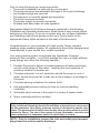
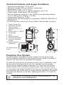
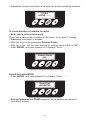
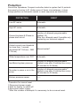
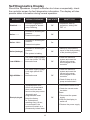
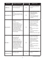
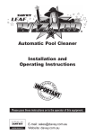
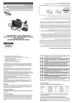
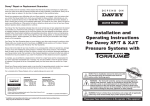
Installation and
Operating Instructions for
Davey Speedman Compact
Constant Water
Pressure Systems
NOTE: Prior to installation remove the inlet and outlet
pipe transport plugs & associated seals from the
suction and/or discharge ports.
WARNING : The Speedman Compact system and associated pipework operate
under pressure. Under no circumstances should the Speedman Compact
System or associated pipework be disassembled unless the internal pressure
of the unit has been relieved. Failure to observe this warning will expose
persons to the possibility of personal injury and may also result in damage to
the pump, pipework or other property.
WARNING: Failure to follow these instructions and comply with all applicable
codes may cause serious bodily injury and/or property damage.
Please pass these instructions on to the operator of this equipment.
Prior to using this pump you must ensure that:
• The pump is installed in a safe and dry environment
• The pump enclosure has adequate drainage in the event of leakage
• Any transport plugs are removed
• The pipe-work is correctly sealed and supported
• The pump is primed correctly
• The power supply is correctly connected
• All steps have been taken for safe operation
Appropriate details for all of these items are contained in the following
Installation and Operating Instructions. Read these in their entirety before
switching on this pump. If you are uncertain as to any of these Installation
and Operating Instructions please contact your Davey dealer or the
appropriate Davey office as listed on the back of this document.
Congratulations on your purchase of a high quality, Davey constant
pressure water pressure system. All components have been designed and
manufactured to give trouble free, reliable operation.
Your new pressure system incorporates the Speedman Compact,
electronic flow controller – a unit that enables the use of a highly efficient
pump design and offers the following benefits:–
1. Enables the pump to deliver a constant pressure of water particularly
across a wide range of flow rates – reducing the inconvenience of
pressure variation in showers etc.
2. Provides automatic “cut-out” protection should the pump run out of
water, should the pump fail to start due to low voltage or a blockage in
the pump.
3. Provides warning indications for system faults.
4. Has adjustable pressure setting to allow for various operating
conditions.
5. Automatic retry functions in the event of a variety of system faults.
6. Motor overload protection included.
Before installing your new pump system, please read all instructions carefully as failures caused by incorrect installation or operation are not covered
by the guarantee. Your Davey pressure system is designed to handle clean
water. The system should not be used for any other purpose without specific
referral to Davey. The use of the system to pump flammable, corrosive and
other materials of a hazardous nature is specifically excluded.
NOTE: Prior to installation remove the inlet and outlet pipe transport
plugs from the suction and/or discharge.
2
Technical Features and Usage Conditions
228
• Operational temperature: 0ºC to +40ºC
• Maximum humidity: 50% at +40ºC (no condensate)
• Temperature of fluid: +1ºC to +40ºC
• Nature of fluid: water with no chemical additives (ph 5 to 9)
• Power Supply: Single phase: 230 Vac 50Hz*
230
• Set point pressure: preset at
2.5 bar (250kPa) and adjustable between
1.0 to 7.5 Bar (100 to 750kPa), ± 0.2 Bar
• Overpressure Maximum: 12 Bar
• Electric safety and electromagnetic compatibility: EN60730, EN61000-6-3,
EN61000-6-4
*For 60Hz operation consult your Davey Water Products dealer for advice.
11
1. Pump Priming Plug
2. Speedman Compact
Control Module
3. Discharge Outlet (11/4”
BSPF)
4. Suction Inlet (11/4” BSPF)
5. Pump Body
6.Motor
7. Rotary Coupling
8. Motor Mounting Bolts
9. Controller Mounting
Screws
10.Support Bracket
Capscrews
175
3
2
2
9
620
9
7
6
4
5
4
1
125
All measurements
in mm.
3
8
10
256
460
Preparing Your System
On removing your Speedman Compact system from the carton check
that the standard orientation of the pump inlet and controller is suitable. If
required, the inlet can be re-orientated 180 degrees.
To rotate the pump inlet to the alternate position, prior to installation, undo
the two motor mounting bolts (8), the four controller mounting screws
(9) and the two support bracket capscrews (10). The pump can then be
rotated relative to the controller by loosening the rotary coupling slightly
(7). Re-position the support bracket to the holes on the opposite end of the
mounting base and re-affix with the support bracket capscrews. Re-position
the pump and controller on the base, tightening all items (7, 8, 9 and 10)
carefully.
Only connect the discharge pipework to the discharge port. The
priming port is not a discharge port.
3
Choosing a Site
Choose a site with a firm base and as close to the water source as
possible with correct power supply. Make sure your pressure system is
always connected to an adequate, reliable source of clean water.
Housing your Davey Pressure System
To protect your pressure system from the weather,
make sure the pump house is both water proof,
frost free and has adequate ventilation. The pump
should be horizontally mounted on a firm base
allowing for drainage, to avoid damage to flooring
etc., that over time may occur from leaking pipe
joints or pump seals. Do not mount the pump
vertically.
WARNING: Some insects, such as small ants, find electrical
devices attractive for various reasons. If your pump enclosure is
susceptible to insect infestation you should implement a suitable
pest control plan.
Power Connection
Connect lead to power supply (220-240V 1phase 50Hz) as designated
on controller label. Note that while the pump motor is rated three phase,
the single phase supply is inverted to suit in the controller. Do not use
long extension leads as they cause substantial voltage drop, poor pump
performance and may cause motor overload.
The Davey Speedman Compact fitted to this pump has a status indicator
mounted on its front panel. This will be illuminated whenever the Speedman
Compact senses that there is electrical power available. It will only work
when unit is connected to the correct electrical supply.
The electrical connections and checks must be made by a
qualified electrician and comply with applicable local standards.
Electrical Power Surge Protection
An electrical power surge or spike can travel on the supply lines and cause
serious damage to your electrical equipment. The Speedman Compact
controller fitted to this system has a metal oxide varistor (MOV) fitted to
help protect it’s circuit. This MOV is a “sacrificial” device, meaning that it
effectively is gradually damaged every time it takes a surge. The MOV is
not a lightning arrestor and may not protect the control unit if lightning or a
very powerful surge hits the pump unit.
If the installation is subject to electrical power surges or lightning we
strongly recommend the use of suitable additional surge protection devices
on ALL electrical equipment.
4
In accordance with AS 3350.2.41 we are obliged to inform you that this
appliance is not intended for use by young children or infirm persons unless
they have been adequately supervised by a responsible person to ensure
that they can use the appliance safely.
Young children should be supervised to ensure that they do not play with
the appliance.
NOTE: For protection, the Davey Speedman Compact controller is
equipped with an automatic reset current sensing overload, constant
tripping of this overload indicates a problem e.g. low voltage at pump,
excessive temperature (above 50°C) in pump enclosure.
Pipe Connections
For best performance use P.V.C. or polythene pipes at least the same
diameter as the pump’s inlet and delivery outlet openings. Larger diameter
pipe may be used to minimise resistance to flow when pumping longer
distances.
Do not use pipe thread sealing compounds on any part of this
pump. ONLY use Teflon sealing tape.
Use unions at pipe connections to enable easy
removal and servicing. Use sufficient tape to
ensure airtight seal and hand
tighten only. To prevent strain on pump threads
always support heavy inlet and outlet pipes. If
there is a likelihood the water supply
may contain solid particles such as pieces of plant
or vegetable matter, a filter should be installed
before the pump to avoid blocking of water ways.
Lay suction pipe at a constant gradient to avoid
air pockets which may reduce pump efficiency.
NOTE: Suction leaks are the largest cause of poor pump
performance and are difficult to detect. Ensure all connections
are completely sealed using thread tape only.
Extra Draw-off Capacity
The Speedman Compact has an in-built accumulator which will accommodate small
leaks. In some applications it may be appropriate to install additional accumulator
(Supercell pressure tank) capacity. These applications includes:
• Long suction lines (see Suction Lines / Lift)
• Low flow appliances connected to the pump, such as evaporative air
conditioners, slow filling toilet cisterns.
Any additional accumulators can be installed downstream of the controller (ie.
between the controller and the first outlet).
Where extra draw-off capacity is utilised
the additional pressure tank should have
a pre-charge 15kPa below the system
pressure setting.
DO NOT USE THREAD
SEALING COMPOUNDS,
HEMP OR PIPE DOPE!
5
Installations with flooded suction require a
gate or isolating valve so water supply can be
turned off for pump removal and servicing.
Abrasive Materials
The pumping of abrasive materials will cause damage to the pressure
system which will then not be covered by the guarantee.
For Automatic Pressure Pumps
Installed with a Mains Pressure
Hot Water System
To protect your system from damage caused
by back pressure from hot water systems. You
should always have installed on the hot water
inlet an approved non-return valve.
NOTE: Always ensure hot water systems are installed in
compliance with manufacturers recommendations and in
accordance with all local regulations.
Connection of Mains Scheme or Town Water
Supply to either Suction or Discharge of Pumps &
Pressure Systems
Most Water Supply
Authorities have strict
regulations regarding direct
connection of pumps to
mains water supplies. In
most cases an isolating
tank is required between
mains supply and pump.
Davey also recommend this
method. Directly applied
mains pressure can exceed pump operating pressure and damage pump.
Davey Water Products Pty Ltd can not accept responsibility for loss or
damage resulting from incorrect or unauthorised installations.
6
Priming and Operation
4. Switch on power - The
status indicator will
be illuminated and
the pump will run.
See section: “Start Up
Procedure”. A full flow
of water should be
discharged from the
open tap.
1. Remove priming plug and fill
casing and suction line (on
flooded suction, simply open
gate valve to pump). When full,
replace priming plug.
2. Ensure outlet nearest
to pump is open.
5. If the pump stops with the
tap open see troubleshooting
checklist.
6. Close the open outlet or tap and
the pump should stop after a few
seconds.
3. Ensure all valves in suction line
are open.
To Reset if Pump switches out in Pump Protection Mode
1. Switch off power.
2. Make sure pump is primed.
3. Open tap, switch on power.
4. Close tap and pump will stop.
Start Up Procedure
• Power the system and in 2 seconds it will display the software variant.
HCW/MT 19/02/07
**By MAC3 SpA**
• Press ENTER to start system without changing any of the factory pre-sets.
• Press + only if you need to alter any of the factory pre-sets.
Installation (+)
Start
(Enter)
7
Changing Pre-sets
NOTE: The unit is factory set to suit low power use and the
pump performance. It is recommended that you only adjust the
“SYSTEM PRESSURE” unless advised by your Davey Water
Products dealer.
The display will scroll through the various settings in order.
Choose with + & Save with ENTER
Language
• Press + or - to change the language.
• Pressing ENTER, the value is saved in memory. Keep ENTER pressed
till it displays “Done..........”
Language
English
Max. Motor Current
• Press + or - to change the value.
• Insert current value as indicated on the pump motor name plate.
• Press ENTER, and keep pressed till it displays “Done..........”
Max. Motor Current
7.5 Ampere
8
System Pressure
• Press + or - to change the value (from 1.00 to 7.50). Note: this has been
factory set at 2.5 Bar.
• Insert the value for desired pressure of the system.
• Press ENTER, and keep pressed till it displays “Done..........”
System Pressure
3.5 Bar
System Start
• Press + or - to change the value (ON/OFF).
ON to activate the system.
OFF not to activate the system.
• Press ENTER, and keep pressed till it displays “Done..........”
System Start
OFF
Save & Exit with ENTER
• Press ENTER, and keep pressed till it displays “Done..........”
Save & Exit
With ENTER
• Saving Parameter and DONE displayed. All parameters are saved in
permanent memory.
Warnings: If System Start = ON, Speedman Compact controller
will immediately power the pump motor!
9
• Speedman Compact controller will display the pre-set operating pressure.
3.5 Bar
ACTIVE ..........
To check direction of rotation for motor
– Note: this is factory set already.
Check the correct sense of rotation of the pump. If you want to change:
• Press key + for about 5 seconds.
• With key ➔ go to the parameter Rotation Sense.
• With key + and - set the value desired for rotation sense (0000 or 0001)
• Press ENTER, and keep pressed till it displays “Done..........”
Rotation Sense
0001
Save & Exit with ENTER
• Press ENTER, and keep pressed till it displays “Done..........”
Save & Exit
With ENTER
• Saving Parameter and DONE displayed. All parameters are saved in
permanent memory.
10
Protection
Should the Speedman Compact controller detect a system fault it protects
the pump by turning it off. Under some of these circumstances, it does
though perform an automatic restart or reset sequence as listed below.
PROTECTION
RESET
Low AC mains
Automatic
High AC mains
Automatic
Ground-to-phase & Phase-tophase short circuit
Number of attempts programmable
(default 10).
After this, attempts reset if possible only
contacting our technical support.
Output current over threshold
for more than 1 second
(threshold MT 12A rms – MM
17A rms)
Manual restart*
Water temperature over 75ºC
Automatic
Insufficient system pressure
Number of attempts programmable**
(default once after 5 minutes then every
50 minutes for 24 times)
No water in pump or air in the
pump
Number of attempts programmable**
(default once after 5 minutes then every
50 minutes for 24 times)
Broken pressure sensor
–––
*Procedure for manual reset.
1.Disconnect power supply
2.Wait for display to switch off
3.Reconnect power supply
**After this number of attempts it is necessary to do a manual reset.
11
Self Diagnostics Display
Should the Speedman Compact controller shut down unexpectedly, check
the controller screen for fault diagnostics information. The display will also
provide status information during normal operation.
MESSAGE
Disabled.........
Active.........
MESSAGE MEANING
PUMP STATE
• Controller engaged but
not engaged for electropump checking
Off
• Controller is checking the
pressure
WHAT TO DO
• Repeat the start-up
procedure, setting ON/
OFF = 1
Off
• Pressurised system
Active..1.0.0...
• Controller is checking the
pressure
On
• Pressurised system
Active (leakage)
• Controller is checking the
pressure
Off
• Attempt to eliminate the
cause of the faulty sealing
of the plumbing system
Off
• Check the electrical
system and reset the
values to the range
as envisaged for the
controller
• The system is leaking
• The power supply voltage
is too low (under 170 Vac)
Low ACMain...... • Automatic reset
• The power supply voltage
is too high (above 270
Vac)
High ACMain...... • Automatic reset
Off
• Check the electrical
system and reset the
values to the range
as envisaged for the
controller
• Check if there is air in
pump and eliminate it
• Eliminate the short-circuit
• A phase/phase short
circuit or a phase/earth
short circuit has been
found on the pump motor
Short ph-ph-gnd.
• Automatic and
programmable reset
• Set at the factory
for 5 attempts at
resetting every 10 sec;
if unsuccessful, the
system will remain in a
permanently locked state
12
• Check the correct motor
insulation
Reset:
Off
1 Disconnect the power
supply
2 Wait for the display to
switch off
3 Restore the power supply
MESSAGE
..STOP CC......
MESSAGE MEANING
PUMP STATE
• After 10 reset attempts
for short circuit ph-ph-gnd
of the electropump
Off
• Water temperature above
75ºC
High temperature
Press.Insuff......
• Automatic reset when the
temperature falls to under
60ºC
Off
WHAT TO DO
• For reset is necessary to
contact Davey technical
support
• Check that the incoming
water temperature
is within the product
specifications
• Check and restore the
correct pump priming
condition
• High flow and very low
pressure
• Eliminate the high flow,
usually a broken pipe
• Automatic reset
• Restore correct pump
priming condition
• (Set at the factory for 1
resetting attempt every 5
minutes if unsuccessful
the reset operation will
be attempted every 50
minutes for 24 times.
After which the system
will remain in permanently
blocked state)
• Check that any inline
filters are not clogged
Off
Reset:
1 Disconnect the power
supply
2 Wait for the display to
switch off
3 Restore the power supply
• Electro-pump off
• Check that the water is
present in the supply
• Automatic and
programmable reset
• Restore correct pump
priming condition
• (Set at the factory for 5
resetting attempt every 5
minutes if unsuccessful
the reset operation will
be attempted every 50
minutes for 24 times.
After which the system
will remain in permanently
blocked state)
• Check that any inline
filters are not clogged
• Lack of water found
No water......
ProSensor Fault.
• A pressure sensor fault
has been found
Off
Reset:
1 Disconnect the power
supply
2 Wait for the display to
switch off
3 Restore the power supply
Off
• Consult the assistance
service
...continued overleaf.
13
MESSAGE
MESSAGE MEANING
PUMP STATE
• An excessive amount
of electrical current is
registered in the pump
WHAT TO DO
• Verify that the pump
is used in conditions
suggested by the
manufacturer
Imax fault
Off
• Make sure that there are
no points of friction or
blocking with regard to
the rotor
• Do the setting sequence
to set the MaxCurr
parameter
Maintenance Menu and Extended Menu
During normal operation the Maintenance Menu is available. It displays
some parameters regarding the functioning of the controller. The Extended
Menu is only available via password.
Note: We strongly advise you NOT to alter settings for these menus.
These menus are intended for trained service persons only.
Maintenance
WARNING : Under no circumstances should the Speedman Compact
controller be disassembled by other than qualified tradespersons. Failure
to observe this warning may expose persons to the possibility of personal
injury and may also result in damage to other property. Do not dismantle
spring under pressure.
The only regular attention your new pressure system may require will be
if you have used an additional pressure tank. You will need to check the
pressure tank’s air charge every 6 months. This can be checked at the air
valve with a tyre gauge. Do not charge tank to a higher pressure than that
shown in the table on page 6.
To check air pressure in tank:
1. Switch off pump.
2. Open outlet nearest to pump to release water pressure.
3. Charge tank to required pressure using air pump and
check with tyre gauge.
4. Switch on.
5. Close outlet.
Warning: Automatic resets may allow the pump to restart without warning.
Always disconnect the pump motor from the electrical supply before
maintenance or repairs.
WARNING: When servicing or attending pump and/or controllers, always
ensure power is switched off and lead unplugged. Electrical connections
should be serviced only by qualified persons.
14
NOTE: For protection, the Davey® pump controller monitors input
current and will shut down the pump motor in the event of an over
load.
WARNING: When servicing or attending pump, always ensure
power is switched off and lead unplugged. Electrical connections
should be serviced only by qualified persons. If the electrical
supply lead of this pressure system is damaged, it must be
replaced.
Care should also be taken when servicing or disassembling
pump to avoid possible injury from pressurised water. Unplug
pump, relieve pressure by opening a tap on the discharge side
of the pump and allow any hot water in the pump to cool before
attempting to dismantle.
During servicing, use only approved, non-petrochemical based
oring and gasket lubrication. If unsure, consult your Davey Dealer
for advice.
WARNING: Do not use hydrocarbon based or hydrocarbon
propelled sprays around the electrical components of this pump.
15
Davey® Repair or Replacement Guarantee
In the unlikely event in Australia or New Zealand that this Davey product develops any malfunction
within two years of the date of original purchase due to faulty materials or manufacture, Davey will at
our option repair or replace it for you free of charge, subject to the conditions below.
Should you experience any difficulties with your Davey product, we suggest in the first instance that
you contact the Davey Dealer from which you purchased the Davey product. Alternatively you can
phone our Customer Service line on 1300 367 866 in Australia, or 0800 654 333 in New Zealand, or
send a written letter to Davey at the address listed below. On receipt of your claim, Davey will seek to
resolve your difficulties or, if the product is faulty or defective, advise you on how to have your Davey
product repaired, obtain a replacement or a refund.
Your Davey Two Year Guarantee naturally does not cover normal wear or tear, replacement of product
consumables (i.e. mechanical seals, bearings or capacitors), loss or damage resulting from misuse
or negligent handling, improper use for which the product was not designed or advertised, failure to
properly follow the provided installation and operating instructions, failure to carry out maintenance,
corrosive or abrasive water or other liquid, lightning or high voltage spikes, or unauthorized persons
attempting repairs. Where applicable, your Davey product must only be connected to the voltage
shown on the nameplate.
Your Davey Two Year Guarantee does not cover freight or any other costs incurred in making a claim.
Please retain your receipt as proof of purchase; you MUST provide evidence of the date of original
purchase when claiming under the Davey Two Year Guarantee.
Davey shall not be liable for any loss of profits or any consequential, indirect or special loss, damage
or injury of any kind whatsoever arising directly or indirectly from Davey products. This limitation
does not apply to any liability of Davey for failure to comply with a consumer guarantee applicable to
your Davey product under the Australian or New Zealand legislation and does not affect any rights or
remedies that may be available to you under the Australian or New Zealand Consumer Legislation.
In Australia, you are entitled to a replacement or refund for a major failure and for compensation for
any other reasonably foreseeable loss or damage. You are also entitled to have the goods repaired
or replaced if the goods fail to be of acceptable quality and the failure does not amount to a major
failure.
Should your Davey product require repair or service after the guarantee period; contact your nearest
Davey Dealer or phone the Davey Customer Service Centre on the number listed below.
For a complete list of Davey Dealers visit our website (davey.com.au) or call:
AUSTRALIA
NEW ZEALAND
Davey Support Centre
6 Lakeview Drive,
Scoresby, Australia 3179
Ph:
1300 367 866
Fax:
1300 369 119
Website:davey.com.au
Davey Support Centre
7 Rockridge Avenue,
Penrose, Auckland 1061
Ph:
0800 654 333
Fax:
09 527 7654
Website:daveynz.co.nz
Davey Water Products Pty Ltd
Member of the GUD Group
ABN 18 066 327 517
® Davey & Speedman are registered trade marks of Davey Water Products Pty Ltd.
© Davey Water Products Pty Ltd 2011.
P/N 401589-2 supersedes P/N 401589-1
* Installation and operating instructions are included with the product when purchased new.
They may also be found on our website.
16