1
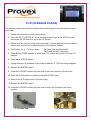
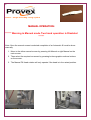
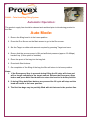
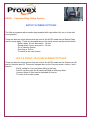
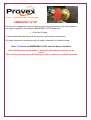
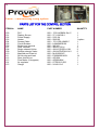
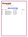
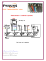
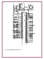
1 Installation and Operating Instructions For the PA820 Twin Head Filler April 2007 Models PA820TV and PA820MV New Fill Valve Plus Options 14 Kimberly Road Dandenong South Victoria Australia 3175 Phone +61 3 9706 6778 Fax +61 3 9706 6779 2 P PA A882200 – –T Tw wiin nH Heeaad dB Baag gF Fiilllliin ng gS Syysstteem m Installation and Operating Instructions MAIN SERVICES REQUIRED Floor Space Required- 1400W X 1500D X 1600 H. Electrical Power Supply- 200-240 V @ 50/60 Hz (Single Phase) 10 amps (3 pin General Purpose Outlet) Air Compressed Air Supply - Min 600 kPa. Approx 10m3 /hr of clean dry air (Connection via “ 1/ 4”BSP Female air fitting) Product Product Supply Rate - 10-220 liters per minute. Maximum Fill Pressure 300 Kpa (Connection via 1 Tri-clover hose tail) By 14 Kimberly Road Dandenong South Victoria 3175 Phone 61 3 9706 6778 Fax 61 3 9706 6779 [email protected] 3 PA820 –Twin Head Bag Filling System INSTALLATION DETAILS Each machine is supplied ready to operate but the following items will require your attention. - Basic Accessories 1 - Product hose 40mm - 1300mm long 2 –40mm Tri-clover clamps 2 –Flow Meter adaptors 1 –50mm Flow Meter Tri-clover clamp 2 –40mm Tri-clover gaskets 2 - C.I.P. adaptor backflow valve with 25mm Tri clover end fittings - Basic Seals Kit 2 –Tri-clover seals 2 –Fill piston O ring seals 1 –Plunger O ring 3 –Swivel O rings 1 –Tube of valve lubricant 2 –Filler valve face seals - International Seal Kit 6 –Tri-clover Seals 3 –Fill Piston O ring seals 3 –Plunger O rings 6 –Swivel O rings 1 –Tube of Valve lubricant 6 –Filler valve face seals 1. Adjust machine feet so that machine is stable and level. 2. Assemble the product hose onto the fill head and the other end onto the top of the flow meter via the flow meter mounting bracket of the rear of the machine. NB: This flow meter is directional type and must be mounted with the ARROW in the direction of flow. 3. Adjust the table top into place and tighten clamping Knobs. Test the height of the table by using a filled bag and checking the desired spout space at the top of the bag. 4. Connect air supply to the filter regulator port on the side of the machine please do not adjust the regulator as this is factory set and should not be altered. 5. Connect to a 240-volt supply. Check for the screen to illuminate, if not inspect the breaker inside the rear cabinet. Make sure the EMERGENCY STOP button is not latched in. Keep hands clear of the mechanism and turn the POWER switch to ON. Please note: Even though the machine is fully cleaned before transport to you we advise that a full C.I.P be completed before any production commences. 4 PA810 –Single Head Bag Filling System C.I.P (CLEAN IN PLACE) The product supply line should be cleaned and sanitized prior to introducing the product to the filler. 1. Ensure the machine is in the home position. 2. Press the GO TO SETUP & CIP on the Main screen to go to the SETUP screen then press the CIP button to go to the CIP Screen 3. Ensure that the vacuum pump is disconnected / removed and the lid to the vacuum tank is open to allow for complete flushing of the vacuum system. 4. Set/Confirm the 4 - CIP cycle times: Tip Open Time (0-99 seconds) Tip Closed Time (0-5 seconds) 5. Press BOTH START buttons on either side. The Heads will moves UP to the CIP position. 6. Press either E/STOP Button 7. Clamp both the CIP adaptors to the fill spout with the 2”Tri-Clover fitting supplied. 8. Release the E/STOP button 9. Push BOTH START buttons on each side to start the continuous Pulse cycle. 10. When the CIP process is complete push the E/STOP button 11. Remove the CIP adaptor and Tri-Clover fitting. 12. Release the E/STOP button 13. Push BOTH START buttons on each side to return the fill head to the home position. C.I.P ADAPTOR C.I.P ADAPTOR FITTED 5 PA810 –Single Head Bag Filling System MANUAL OPERATION: ****** Warning in Manual mode Two hand operation is Disabled ****** Note: Once the manual screen is selected completion of an Automatic fill must be done manually. 1. Move to the either manual screen by pressing left Manual or right Manual on the main screen. 2. Then select the required movement by pressing buttons graphic sections buttons on the screen. 3. The Manual Fill Head rotation will only operate if the head is in the raised position. 6 PA820 –Twin Head Bag Filling System Automatic Operation: The product supply line should be cleaned and sanitized prior to introducing product to the filler. Auto Mode: 1. Ensure the filling head is in the home position. 2. Press the Run Screen on the Main screen to go to the Run screen. 3. Set the Target on either side amount required by pressing Target and save. 4. Ensure that the vacuum pump is ON and sufficient pressure (approx. 20-60kpa) has built up. (If this option is installed) 5. Place the spout of the bag into the bag fork. 6. Press both Start buttons. 7. On completion of the filling of the bag the filler will return to its home position. Notes: 1. If the Emergency Stop is pressed during filling the fill valve will close and will no longer complete to the target amount. Release the Emergency Stop button and press both Start buttons to return the head to its home position. 2. If during filling both Start buttons are pressed the fill cycle will stop and the head will return to its home position. 3. The first few bags may be partially filled with air that was in the product line. 7 PA820 –Twin Head Bag Filling System SETUP SCREEN OPTIONS: The filler is programmed to handle bags supplied with caps either fully on or in the dust cover position. There are also two other options that are used in the AUTO mode are the Return Delay and the recap delay. These are changed also on the setup screen via the touch buttons. Return delay .01 sec amounts 0 - .99 sec Recap delay .01 sec amounts 0 - .99 sec Go to Vacuum Screen Dust Cap or Full on To return to the main screen LEFT & RIGHT VACUUM SCREEN OPTIONS: There are also two other options that are used in the AUTO mode are the Vacuum pre fill and the Vacuum post fill. These are changed also on the Vacuum screen via the < and > buttons. Pre fill setting for Vacuum before filling of the bag Post fill vacuum once the fill head has lifted to catch any drips Vacuum Option if fitted can be switched off and on To return to the main screen 8 PA820 –Twin Head Bag Filling System YOKOGAWA FLOW METER (Option) Magnetic Flow Meter Setting The standard Magnetic Flow meter used by PROVEX is a Yokogawa AXF gives High Accuracy and Repeatability. Settings: 1000 pulses per Litre Transistor signal 4-20mA = 0-3 Litre per second (Not Used) Non Factory Setting B02: set to .1 B03: set to Flow Span = 3.000 B04: set to Flow Unit = L B05: set to Time Unit = /s D01: set to Rate F01: set Pulse to = UNIT/P F02: set Pulse scale to = .001 TURBINE FLOW METER (Option) Turbine Flow Meter The standard Turbine Flow meter used by PROVEX is a PROCESSAUTOMATIC Turbine Flow Meter type unit which also gives High Accuracy and Repeatability. Settings: 1”t ur bi ne 220 pulses per Litre signal (approx) Via a two pin Military plug Pre amplifier back to the PLC No Factory Setting is required as it is a totaled sealed unit When product is flowing Input 0 will flash to confirm turbine is working Installation: The flow meter must be installed with the marked arrow in the matching direction of the flow. 9 PA820 –Twin Head Bag Filling System EMERGENCY STOP This function is designed to stop the filler and place the mechanism in the safe position at any stage of operation. Pushing the EMERGENCY STOP button will: Close the fill head To reset press both start buttons at the machine will complete its operation. For safety reasons the mechanism will not swing horizontally or release the cap. Note: To Release the EMERGENCY STOP, twist the button clockwise. When the Emergency stop button is pressed it will display a message on the screen This message will clear when the Emergency stop is released or CLEAR is pressed 10 PA820 –Twin Head Bag Filling System Maintenance Requirements As per any process machine standard maintenance is required and upkeep is important to guarantee production reliability. Daily Maintenance Requirements: Make sure the machine has been cleaned and washed down properly making shore that product has not set to the machine and that C.I.P completed. Check vacuum tank is clean and empty of fluid. Check all Product line seals are in place and all clamps are tight. Check that the face seal is OK and not damaged. Clean and check both product seals in the fill stem are clean and not worn Check that the Spout Plate, Capper Bracket and fill head are aligned. Check that the Cap Detection Photo cell is working properly (if fitted). Test Emergency Stop Button if working Check for loose equipment or items that may have come loose. Weekly Maintenance Requirements: Remove and inspect all product line seals check if they are in good condition, Replace if required. Check the fill head cylinder base seal to see if it is leaking unscrew and replace BOTH with spares supplied with filler (part 810-0143) look for product above the seal. Check the rear cabinet door seal for leaks adjust lock. Test Emergency Stop Button if working. Check Air Regulator for water (If full empty by pushing up the base and check Compressor). Strip down the product valve and inspect by releasing the tri-clover fitting Tighten fill plunger onto cylinder shaft if it has come loose, (hand tight) Danger!!!! Check to make sure that the product pump is not still running And the air is shut off. 11 PA820 –Twin Head Bag Filling System Options Section Guarding Automatic or Manual Splash Guard System Due to the Danger of hot products one of the options on our filler is an automatic splash guard which rises out of the way to allow easier spout insertion to the filler fork. The guard is controlled by the capper cylinder air circuit and is interlocked with a Guard master safety system which has final control over the fill valve. If at any time during filling process the guard is lifted the fill valve will shut, until the guard is lowered to the safe position. Hot fill table At certain times during the filling process Spills can occur this can cause unwanted Products landing on the floor or the operators We also offer a 10 liter hot fill table which in most cases will catch and funnel the pr oductdowna1½ “or40mm t r icl ov erf i t t i ng. 12 PA820 –Twin Head Bag Filling System Mass Flow meter Option If a Mass flow meter is installed on the filler, selection between the flow meters is not required. Info to follow 13 PA820 –Twin Head Bag Filling System PARTS LIST FOR THE FILLING SECTION ITEM No NAME PART NUMBER QUANTITY 1 2 3 4 4a 5 6 7 8 9 10 11 12 13 14 15 16 17 18 19 20 21 22 23 24 25 26 27B 28 29B 30 31B 32B 33 34 35 36 Lift Cylinder Lift Cylinder Proximity Shaft Body Case Main Shaft and Lock cap Main Shaft Swivel Bush Shaft Sleeve Shaft Pivot Bar Shaft Pivot Bolt Shaft Pivot 7/16”rod end Shaft Pivot Lock Nut Shaft Pivot Cylinder Shaft Pivot Cylinder proximity Base Plate Base Plate Fixing Bolts Spout Plate* Spout Plate Bolts Fill Head Bracket Fill Head Bracket Center Bolt Fill Head Bracket Pivot Bolts Capper Bracket Capper Cylinder Capper Spacer Capper Clamping Block Capper Clamping Block nut Capper Fork Bracket * Product Line Support Body Product Line Swivel O Ring Kit Fill Cylinder Base Fill Cylinder Fill Cylinder Base O rings Fill Cylinder Tri clover & Seal Fill Cylinder Plug Fill Cylinder Plug O ring Fill Cylinder spout Face Seal Fill Cylinder Body Fill Cylinder Top Cap Fill Cylinder Base O ring 820 - PC- 311.5 –DBMWQ 820 - MRS-087-XBL-31 820 –0101 820 –0102 820 –0108 820 –0103 820 –0104 820 –0105 820 –0106 820 –0107 820 - PC - 171.5 –DXPBMW 820- MRS –087-XBL-17 820 –0110 820 –0111 820 –0115* 820 –0116 820 –0120 820 –0121 820 –0122 820 –0130 820 –PC –171 –DXPBMW 820 –0131 820 –0132* 820 –0133 820 –0134* 820 –0140 820 –0141 820 –0142 820 - CPC-0353-A-2.5 820 –0143 820 –0144 820 –0145 820 –0146 820 –0147 820 –0148 820 –0149 820 –0150 2 4 2 2 2 2 2 2 2 2 2 4 2 8 2 8 2 2 4 2 2 2 2 2 2 2 6 2 2 4 4 2 2 2 2 2 2 * Note: These items Alter depending on the particular bags being filled Spout info required 14 PA820 –Twin Head Bag Filling System PARTS LIST FOR THE CONTROL SECTION ITEM No NAME PART NUMBER QUANTITY 100 101 102 103 104 105 106 107 108 109 110 111 112 113 114 115 PLC Display Screen Power Supply Heater Screen Cable Circuit Breaker Single type terminal Dual Terminal Single solenoid Valve Double solenoid Valve Manifold end Plate kit 24Vdc plug and lead Rear control box Flow Meter (Yokogawa) Air regulator Gauge 820 –1762-L40BWA Ser C 820 –2711-M518L1 820 –S-25-24 820 –SK3105 820 –1761-CBL-HM02 C 820 –LAN45MCB106 820 –WK 4/U 820 –WKN 2.5 E/U 820 –45A-LCD-DDAJ-1KJ 820 –45A-NCD-DDAJ-1KJ 820 –M-45008-01P 820 –E392N3001ACH 820 –AE1024 820 –AE202HM # 820 –CFDR10-2-S/S 820 –24142-16-0 1 1 1 1 option 1 1 1 3 2 6 1 14 1 1 1 1 15 PA820 –Twin Head Bag Filling System PARTS LIST FOR THE FRAME ITEM No NAME PART NUMBER QUANTITY 200 201 202 203 204 205 206 Main Frame Body Display Screen Enclosure Display Enclosure Brackets Machine Feet (option 1) Machine Casters (option 2) Product hose Type 1 Product hose Type 2 (oil) 820 –01502 820 –01512 820 –01522 820 –0160-50 820 –0161-100 820 –0170 820 –0171 1 1 2 4 4 2 2 16 PA820 –Twin Head Bag Filling System Air Manifold and hose layout Pneumatic Control System Guard Yellow Dark Blue White Red Light Blue Black Orange Green Black 4 mm Twin System one for each side Air Requirements for the filling system: Min 600 kPa. 10m3/hr of dry clean air. Connection by ¼”BSP female port. 17 PA820 –Twin Head Bag Filling System Vacuum Control System (Optional System) This Option allows the operator to select the required pre fill and post fill vacuum time on the PA810 filler Do not use Vacuum System on thick products or liquids that contain particulates. To setup complete the following instructions: 1 - Check the vacuum tank is empty (open lid and inspect inside) if fluid present Flush out. 2 - Shut the drain valve at the base of the tank (If fitted). 3 - Connect an air supply the Regulator on the Vacuum tank this must be separate supply other than the filler. 4 - Connect the suction line from the filler to the Vacuum tank. 5 - Adjust the air regulator on the vacuum tank to give the desired vacuum level check Vacuum Gauge on the top of the tank -20 to -60 Kpa. 6 –From the Main screen press setup button and move to the Setup screen then press F2 again to move to the Vacuum screen this will give you the full vacuum options. Vacuum Off / On Vacuum Pre fill time 0 –5 sec 1/100th of a sec increment Vacuum Post fill time 0 –9.9 sec 1/100th of a sec increment Main Screen 7 –Once the settings are complete they will remain until altered again. If Vacuum is selected on filler built after April 6, 2005 a new pulse System will operate keeping the tip clear of product for 10 minutes after the last bag is filled. The vacuum valve will pulse to clear the Spout every 5 sec for 1 second to suck up residual drips. This will not affect your vacuum settings but work in conjunction with Them. Vacuum Kit 18 PA820 –Single Head Bag Filling System PARTS LIST FOR THE VACUUM SYSTEM ITEM No NAME PART NUMBER QUANTITY 300 301 302 303 305 306 Vacuum Tank 18 Litres Vacuum Pump and Regulator Vacuum Actuator Long 900mm Vacuum Hose Kit Vacuum Airline Kit Single solenoid Valve 820 –0300 820 –0301 820 –0302 820 –0303 820 –0305 820 –45A-LCD-DDAJ-1KJ 1 1 2 3 2 2 PARTS LIST FOR THE SPLASH GUARD ITEM No NAME PART NUMBER QUANTITY 400 401 402 403 404 405 406 Lexon Clear Guard Guard lift Cylinder and base Cylinder rod end Safety Switch and relay Kit 820 –0400 820 –PC- 55 - DBMWQ 820 –0402 820 –440N-C02076 2 1 option 1 option 1 option PARTS LIST FOR THE HOT FILL TABLE ITEM No NAME PART NUMBER QUANTITY 500 501 700 X 700 Bounded table Strainer trough guard 820 –0500 820 –0501 1 1 Parts List for Provex Approved Check Scale 0-150 Kg ITEM No NAME PART NUMBER QUANTITY W60 60 Kg weights and measures bench Scale PA800 –W60 1 19 AC240VOLT POWERSUPPLY DC24VOLT1.2AMP F1 F2 F3 F4 24- 24+ + Provex PA820M control circuit - 20 Provex Parts Drawings 28 35 17 18 18 30 16 20 4 26 27B 29B 30 32B 4a 36 34 19 31B 33 21 23 22 5 9 3 10 6 14 8 7 1 24 21 22 23 24 25 26 27