Transcript
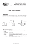
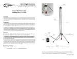
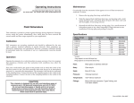
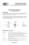
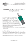
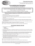
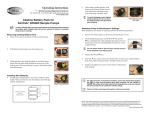
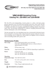
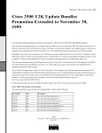
Operating Instructions
R
863 Valley View Road, Eighty Four, PA 15330, USA
Tel: 724-941-9701 e-mail: [email protected]
The SKC Aluminum Cyclone is a lightweight respirable dust sampler that is used with a
filter loaded into a three-piece filter cassette. The filter material, pore size, and the
support pad must be selected as specified by the sampling method used. The cyclone
separates the dust particles according to size. The respirable particles collect on a filter
for analysis while larger particles fall into the grit pot and are discarded.
2.5 L/min for ACGIH/ISO/CEN Convention (nominal D=4.0 µm)*
2.8 L/min for alternate applications (nominal D=3.5 µm)†
* As previously published, a flow rate of 2.6 L/min will give a 4 µm cut-point, however, 2.5 L/min
will give a better match over the entire curve.
† Determined using experimental data obtained at flows from 2.0 to 4.0 L/min
Note: The ACGIH/ISO/CEN Curve (Soderholm) Convention requires using the flow rate that
minimizes the bias of the cyclone separation from the convention curve.
Operation
3. Insert cyclone into cassette ring and press
firmly. Leave grit pot in place during
calibration and sampling.
4. Insert cyclone/cassette assembly through
large opening of filter cassette holder (see
Figure 3). Ensure assembly is seated firmly in
holder by inserting the cyclone‘s side pin
(small round nodule on rim of cyclone) into
the notch in the filter cassette holder.
5. Secure assembly in holder by stretching
the spring-loaded hold-down plate over the
cassette. Insert adapter (located in end of
rubber tubing) into cassette outlet.
Cassette Outlet
Support Pad
Air Flow
2. Select a filter and support pad as specified
in the sampling method. Insert cassette ring
(middle) section into cassette outlet (see Figure
1).
3. Connect the Tygon® tubing attached to the filter cassette holder to the
inlet of a sampling pump. Using flexible tubing, connect the calibration
chamber to a calibrator.
Figure 2
Calibration
Chamber
5. Disconnect calibrator and replace filter used to set flow with a fresh
weighed filter (unused) for sample collection.
The SKC Aluminum Cyclone
Assembly
1. Disassemble a three-piece cassette and set
aside inlet section (usually marked “inlet”).
Remove plug from cassette outlet.
2. Moisten O-ring inside large end of calibration chamber (Cat. No. 225-0103, see Figure 2) and push chamber over cyclone stem until it fits snugly.
4. Following instructions in the pump and calibrator manuals, calibrate to
required flow rate (see reverse side).
Aluminum Cyclone
25 mm - Catalog No. 225-01-01
37 mm - Catalog No. 225-01-02
Flow rate:
Calibration
1. Prepare a cyclone/filter cassette assembly (see Assembly).
Calibrate the cyclone with grit pot in place.
Filter
Cassette Ring
(middle)
Sampling
1. Ensure flow rate has been
calibrated (see Calibration).
Warning: Leave grit pot in place
during calibration and sampling.
Collar Clip
Filter Cassette
Holder
Rubber Tubing
Adapter
Cyclone/Filter
Cassette Assembly
2. Connect the Tygon tubing
attached to the filter cassette holder to
the inlet of a sampling pump.
Tygon Tubing
3. Clip cyclone/filter cassette assembly
onto a worker‘s collar or pocket near the
breathing zone.
Grit Pot
4. Start pump and record pertinent
details.
Figure 3
Cyclone with filter cassette in holder
5. At the end of the sampling period, stop
pump and record finish time. Remove
cyclone/filter cassette assembly from cassette
holder. Separate cyclone from cassette.
Reassemble inlet section of cassette, ensuring
the inlet and outlet are sealed with plugs. Send cassette and all data to a laboratory for
analysis.
Note: Particles collected in the grit pot do not represent any part of the respirable dust sample
and should be discarded.
6. Prior to further sampling, clean all parts of the cyclone, including the interior of the
grit pot, with mild soapy water. The cyclone may be wiped with a clean dust-free tissue,
air dried, blown dry, or wiped with isopropyl alcohol.
Cyclone
Air Inlet
Accessories
Three-piece Filter Cassette Blanks
Grit Pot
Filter Cassette Holder
Calibration Chamber
Figure 1
Exploded view
of the cyclone/filter
cassette assembly
25 mm
37 mm
25 or 37 mm
25 or 37 mm
Catalog No.
225-3-25LF
225-3LF
225-1
225-01-03
For more information: See SKC Technical Note, Publication 1519, at www.skcinc.com.
Form #3803 Rev 0603