1
Gearmotors \ Industrial Gear Units \ Drive Electronics \ Drive Automation \ Services
Stationary Energy Supply
MOVITRANS® TPS10A Stationary
Converters
Edition 09/2004
11304812 / EN
GC430000
Operating Instructions
SEW-EURODRIVE – Driving the world
Contents
1 Important Notes................................................................................................. 4
2 Safety Notes ...................................................................................................... 6
3 Installation ......................................................................................................... 7
3.1 Type designation, nameplates and scope of supply ................................. 7
3.2 Unit design size 2 (TPS10A040) ............................................................... 9
3.3 Unit design size 4 (TPS10A160) ............................................................. 10
3.4 Serial interface option type USS21A (RS-232) ....................................... 11
3.5 Installation notes ..................................................................................... 12
3.6 UL compliant installation ......................................................................... 14
3.7 Touch guard ............................................................................................ 15
3.8 Wiring diagram, size 2 (TPS10A040)...................................................... 16
3.9 Wiring diagram, size 4 (TPS10A160)...................................................... 17
3.10 Wiring diagram for control unit (TPS10A) ............................................... 19
3.11 Installing and removing a terminal unit.................................................... 21
3.12 Connection of the serial interface option type USS21A (RS-232)........... 22
I
0
4 Startup.............................................................................................................. 23
4.1 Operating status and setpoint selection .................................................. 23
4.2 Startup steps ........................................................................................... 25
5 Operation and Service .................................................................................... 27
5.1 Operation displays .................................................................................. 27
5.2 Fault reset ............................................................................................... 29
5.3 Auto reset function .................................................................................. 29
5.4 Overload capacity ................................................................................... 30
5.5 Cut-off limits ............................................................................................ 31
5.6 Electronics service .................................................................................. 32
kVA
i
f
n
P Hz
6 Technical Data ................................................................................................. 33
6.1 General information ................................................................................ 33
6.2 Line filter ................................................................................................. 33
6.3 Unit data.................................................................................................. 34
6.4 Electronics data ...................................................................................... 35
6.5 Dimensions ............................................................................................. 36
7 Index ................................................................................................................. 39
Operating Instructions – MOVITRANS® TPS10A Stationary Converters
3
Important Notes
1
1
Important Notes
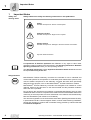
Safety and
warning notes
Betriebsanleitung
Always observe the safety and warning instructions in this publication!
Hazard
Possible consequences: Severe or fatal injuries.
Hazardous situation
Possible consequences: Slight or minor injuries.
Harmful situation
Possible consequences: Damage to the drive and the environment.
Tips and useful information.
A requirement of fault-free operation and fulfillment of any rights to claim under
guarantee is that you adhere to the information in the operating instructions. Read the
operating instructions before you start operating the unit!
The operating instructions contain important information about service and should
be kept in the vicinity of the unit.
Designated use
MOVITRANS® TPS10A stationary converters are intended for use in industrial and
commercial systems for the operation of contactless power transmission systems. Only
connect suitable components to the stationary converter that have been specifically
designed for this purpose, such as the MOVITRANS® TAS10A transformer module.
MOVITRANS® TPS10A stationary converters are designed to be installed in control
cabinets. Observe all instructions on the technical data and the permitted conditions
where the unit is operated.
Do not start up the unit (take it into operation in the designated fashion) until you have
established that the machine complies with the EMC Directive 89/336/EEC and that the
conformity of the end product has been determined in accordance with the Machinery
Directive 89/392/EEC (with reference to EN 60204).
The rules and regulations of the Professional Association (Berufsgenossenschaft, BG),
in particular BG rule B11 "Electromagnetic fields", must be observed during installation,
startup and operation of systems with contactless energy transfer by induction for use
in industrial workplaces.
4
Operating Instructions – MOVITRANS® TPS10A Stationary Converters
Important Notes
Operational
environment
Waste disposal
1
The following uses are forbidden, unless measures are expressly taken to make
them possible:
•
In explosion-proof areas
•
In areas exposed to harmful oils, acids, gases, vapors, dust, radiation, etc.
•
In non-stationary applications with mechanical vibration and shock loads exceeding
the values stipulated in EN 50178
Please follow the latest instructions: Dispose of the following materials in accordance
with the regulations in force:
•
Electronics scrap (circuit boards)
•
Plastic (housing)
•
Sheet metal
•
Copper
etc.
Operating Instructions – MOVITRANS® TPS10A Stationary Converters
5
Safety Notes
2
2
Safety Notes
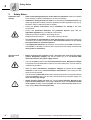
Installation and
startup
•
Never install damaged products or take them into operation. Submit a complaint
to the shipping company immediately in the event of damage.
•
Installation, startup and service work to be executed by trained personnel only
observing applicable accident prevention guidelines and the regulations in force (e.g.
EN 60204, VBG 4, DIN-VDE 0100/0113/0160).
•
Follow the specific instructions during installation and startup of the other
components!
•
Ensure that preventive measures and protection devices apply with the
applicable regulations (e.g. EN 60204 or EN 50178).
Required preventive measures: Grounding the unit
Required protection device:
Operation and
Service
6
Overcurrent protection devices
•
The unit meets all requirements for safe disconnection of power and electronics
connections in accordance with EN 50178. All connected circuits must also satisfy
the requirements for safe disconnection.
•
Take appropriate measures (for example, connect binary input DIØØ "/CONTROLLER INHIBIT" to DGND) to ensure that the system does not startup unintentionally
when power is switched on.
•
Before removing the protective cover, disconnect the unit from the supply
system. Dangerous voltages may still be present for up to 10 minutes after
disconnection from the power supply source.
•
The unit has IP00 enclosure with removed protective cover. Dangerous voltages
are present at all subassemblies except for the control electronics. The unit must be
closed during operation.
•
When the unit is switched on, dangerous voltages are present at the output
terminals as well as any connected cables and terminals. This is also the case
when the unit is inhibited.
•
The fact that the status LED V1 and other display elements are no longer illuminated
does not indicate that the unit has been disconnected from the power supply and
does not carry any voltage.
•
Safety functions within the unit may cause system standstill. Removing the
source of the malfunction or performing a reset can result in an automatic restart
of the system. If safety reasons prohibit, this action, disconnect the unit from the
power supply before correcting the fault.
Operating Instructions – MOVITRANS® TPS10A Stationary Converters
Installation
Type designation, nameplates and scope of supply
3
Installation
3.1
Type designation, nameplates and scope of supply
3
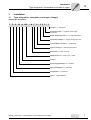
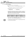
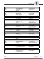
Sample type designation
T P S 10 A 160 - N F 0 - 5 0 3 - 1
Version: 1 = customized
Connection type: 3 = 3-phase power supply
connection
Radio interference level: 0 = no radio interference
Connection voltage: 5 = supply voltage 500 V AC
Line conductor current: 0 = not specified
Type of cooling: F = with heat sink and fan
Enclosure: N = IP10 enclosure
Rated power: 040 = 4 kW / 160 = 16 kW
Version:
Series and generation: 10 = standard
Type of installation: S = stationary
Component: P = power unit
Type: T = MOVITRANS®
Operating Instructions – MOVITRANS® TPS10A Stationary Converters
7
Installation
Type designation, nameplates and scope of supply
3
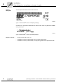
Sample
nameplate
The nameplate is attached to the side of the unit.
Figure 1: MOVITRANS® TPS10A nameplate (example)
51420AXX
Furthermore, a type label is attached to the front of the control unit (above the TERMINAL option slot).
Figure 2: MOVITRANS® TPS10A type label (example)
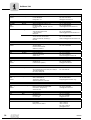
Scope of delivery
8
51426AXX
•
Power section with control unit
•
In addition for size 2 (TPS10A040): One (1) power shield clamp
•
In addition for size 4 (TPS10A160): Two (2) touch guards for the power terminals
Operating Instructions – MOVITRANS® TPS10A Stationary Converters
Installation
Unit design size 2 (TPS10A040)
3.2
3
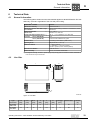
Unit design size 2 (TPS10A040)
[1] [2] [3]
[4] [5]
[6]
[12]
V1
V2
V3
[13]
[14]
[15]
[16]
[17]
G1
[7]
G2
-I
+I
[18]
[8] [9] [10] [11]
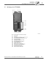
Figure 3: MOVITRANS® TPS10A040 unit design
[1]
[2]
[3]
[4]
[5]
[6]
[7]
[8]
[9]
[10]
[11]
[12]
[13]
[14]
[15]
[16]
[17]
[18]
54706AXX
Power section
Control unit
X1: Power supply connection L1 (1) / L2 (2) / L3 (3)
X5: Connection for power shield clamp
X4: Connection for DC link connection -UZ / +UZ
X4: PE connection (댷)
X2: Gyrator connection G1 (4) / G2 (5)
Terminal has no function
X6: Connection for power shield clamp
X3: Current feedback -I (6) / +I (9)
X3: PE connection (댷)
Operation LEDs V1 / V2 / V3
Retaining screw A for terminal unit
Terminal unit for control leads, detachable
Flap on terminal unit with labeling tile
X10: Electronics terminal strip
Retaining screw B for terminal unit
Screw for electronics shield clamp
Operating Instructions – MOVITRANS® TPS10A Stationary Converters
9
Installation
Unit design size 4 (TPS10A160)
3
3.3
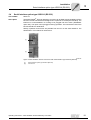
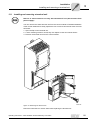
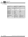
Unit design size 4 (TPS10A160)
[1] [2] [3]
[4]
[5]
[6]
[12]
V1
V2
V3
[13]
[14]
[15]
[16]
[17]
[18]
[7]
[8]
[9]
[10] [11]
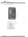
Figure 4: MOVITRANS® TPS10A160 unit design
[1]
[2]
[3]
[4]
[5]
[6]
[7]
[8]
[9]
[10]
[11]
[12]
[13]
[14]
[15]
[16]
[17]
[18]
10
55531AXX
Power section
Control unit
X1: PE connection (댷)
X1: Power supply connection L1 (1) / L2 (2) / L3 (3)
X4: Connection for DC link connection -UZ / +UZ
X4: PE connection (댷)
Terminal has no function
X2: Gyrator connection G1 (4) / G2 (5)
X3: Current feedback -I (6) / +I (9)
Terminal has no function
X3: PE connection (댷)
Operation LEDs V1 / V2 / V3
Retaining screw A for terminal unit
Terminal unit for control leads, detachable
Flap on terminal unit with labeling tile
X10: Electronics terminal strip
Retaining screw B for terminal unit
Screw for electronics shield clamp
Operating Instructions – MOVITRANS® TPS10A Stationary Converters
Installation
Serial interface option type USS21A (RS-232)
3.4
3
Serial interface option type USS21A (RS-232)
Part number
822 914 7
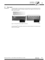
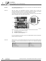
Description
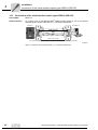
The MOVITRANS® TPS10A stationary converter can be fitted with the isolated interface
RS-232. The RS-232 interface is designed as a 9-pole sub-D socket (EIA standard). The
interface is accommodated in a housing to be plugged into the inverter (TERMINAL
option slot). The option can be plugged in during operation. The transmission rate of the
RS-232 interface is 9600 baud.
Startup, operation and service are possible from the PC via the serial interface. The
SEW SHELL TPS software is used for this.
[1]
V1
V2
V3
[2]
55299AXX
Figure 5: MOVITRANS® TPS10A control unit with serial interface type USS21A (RS-232)
[1]
[2]
Serial interface option type USS21A (RS-232)
Control unit
Operating Instructions – MOVITRANS® TPS10A Stationary Converters
11
Installation
Installation notes
3
3.5
Installation notes
It is essential to comply with the safety notes during installation!
Tightening torques
•
Only use genuine connection elements.
Note the tightening torques of the power terminals:
Size 2 (TPS10A040) → 1.5 Nm (13.3 lb.in)
Size 4 (TPS10A160) → 14 Nm (124 lb.in)
Recommended
tools
•
Only use the following tools to connect the X10 electronics terminals strip. Other
tools will destroy the screw head.
– Phillips Posidrive screwdriver size 1 to DIN 5262 PH1
– Slotted screw driver according to DIN 5265, size 4.0 × 0.8 or 4.5 × 0.8
Minimum clearance and mounting
position
•
Leave at least 100 mm (4 in) clearance at the top and bottom for optimum cooling.
For project planning refer to the section "Technical Data." No clearance is required
at the sides; the units can be lined up in rows. With size 4 (TPS10A160), do not install
any components that are sensitive to high temperatures less than 300 mm (11.81 in)
above the unit.
Install the units vertically. You must not install them horizontally, tilted or upside
down!
Supply system
contactor
•
Only use supply system contactors (K11) of utilization category AC3
(IEC 158-1).
Line choke
•
More than four units on an input contactor for the total current:
Insert a 3-phase line choke in the circuit to limit the inrush current.
Separate cable
ducts
•
Route power leads and electronics leads in separate cable ducts.
Input fuses and
earth leakage
circuit breakers
•
Install input fuses for the line protection (no unit protection) at the beginning of
the supply system lead behind the supply bus junction. Use D, DO, NH or circuit
breakers.
One earth leakage circuit-breaker as sole protection device (exception: allcurrent sensitive earth leakage circuit-breaker) is not permissible. Earth-leakage
currents > 3.5 mA can arise during normal inverter operation.
PE power supply
connection (→ EN
50178)
12
•
If the supply system lead is < 10 mm2 (AWG8), route a second PE conductor with
the cross section of the supply system lead in parallel to the protective earth using
separate terminals. Alternatively, use a protective earth conductor with a cross
section of 10 mm2 (AWG8) Cu. If the supply system lead is ≥ 10 mm2 (AWG8), use
a Cu protective earth conductor with the cross section of the supply system lead.
Operating Instructions – MOVITRANS® TPS10A Stationary Converters
Installation
Installation notes
Line filter
•
3
A line filter is required to comply with class A limit according to EN 55011 and
EN 55014 (→ Sec. "Technical Data"):
NF014-503 (part number: 827 116 X) for MOVITRANS® TPS10A040
NF035-503 (part number: 827 128 3) for MOVITRANS® TPS10A160
•
Install a line filter close to the unit outside the minimum clearance.
•
Limit the length of the cable between the line filter and unit to the absolute
minimum needed.
•
Use twisted and shielded cables for long distances between the control cabinet
and line filter and between the line filter and unit.
IT systems
•
SEW-EURODRIVE recommends using earth-leakage monitors with pulse-code
measurement for power supply systems with a non-grounded star point (IT
systems). This step will prevent the earth-leakage monitor from triggering accidentally due to the grounding capacities of the inverter.
Cross sections
•
Supply system lead: Line cross section according to nominal input current Imains
at rated load.
•
Line cross section between X2/X3 of the TPS10A stationary converter and X2/X3 of
the TAS10A transformer module:
– Size 2 (TPS10A040)→ 4 mm2
– Size 4 (TPS10A160) → 16 mm2
•
Electronics cables:
– One core per terminal 0.20...2.5 mm2 (AWG24...12)
– Two cores per terminal 0.20...1 mm2 (AWG24...17)
Unit output
•
Only connect valid components to the unit, such as the MOVITRANS® TAS10A
transformer module.
Binary inputs /
binary outputs
•
Binary inputs are electrically isolated by optocouplers. Binary outputs are shortcircuit proof but not protected against external voltage. External voltages can
cause irreparable damage!
Shielding and
earthing
•
SEW EURODRIVE recommends that you shield the control cables.
•
Connect the shield by the shortest possible route and make sure it is earthed over
a wide area at both ends. To avoid ground loops, you can ground one end of the
shield via a suppression capacitor (220 nF / 50 V). If using double-shielded cables,
earth the outer shield on the unit end and the inner shield on the other end.
•
You can also route the cables in grounded sheet metal ducts or metal tubes for
shielding purposes. Install the power and signal lines separately.
•
Ground the MOVITRANS® and all additional devices to meet the high-frequency
guidelines. To do so, provide a wide area metal-on-metal contact between the unit
housing and ground (e.g. unpainted control cabinet mounting panel).
Operating Instructions – MOVITRANS® TPS10A Stationary Converters
13
Installation
UL compliant installation
3
3.6
UL compliant installation
Note the following points for UL compliant installation:
•
Only use copper cables with the following temperature ranges as connection
cables:
– For MOVITRANS® TPS10A (size 2 and 4) temperature range 60/75 °C
•
Permitted tightening torques for MOVITRANS® power terminals:
– TPS10A040 (size 2)
– TPS10A160 (size 4)
•
14
→
→
1.5 Nm (13.3 lb.in)
14 Nm (124 lb.in)
MOVITRANS® TPS10A stationary converters are suitable for operation on
voltage supply systems with grounded star point (TN and TT nets) supplying a
maximum supply current according to the following tables and with a maximum
voltage of 500 VAC. Only use fuses as the main safety feature. The performance data
of these fuses must not exceed the values in the table.
MOVITRANS® TPS10A
Max. supply current
Max. supply voltage
Fuses
040 (size 2)
5000 AAC
500 VAC
110 A / 600 V
160 (size 4)
10000 AAC
500 VAC
350 A / 600 V
•
Only use tested units with a limited output voltage (Vmax = 30 VDC) and limited
output current (I ≤ 8 A) as the external 24 VDC voltage source.
•
UL certification does not apply to operation in voltage supply systems with a
non-earthed star point (IT systems).
Operating Instructions – MOVITRANS® TPS10A Stationary Converters
Installation
Touch guard
3.7
3
Touch guard
Touch guard
The MOVITRANS® TPS10A160 (size 4) units include two (2) touch guard elements and
eight (8) retaining screws as standard. Install the touch guard on both covers of the
power section terminals.
Figure 6: Touch guard for MOVITRANS® TPS10A160
01470BXX
The MOVITRANS® TPS10A160 units have an enclosure rating of IP10 with and IP00
without the touch guard.
Operating Instructions – MOVITRANS® TPS10A Stationary Converters
15
Installation
Wiring diagram, size 2 (TPS10A040)
3
3.8
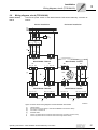
Wiring diagram, size 2 (TPS10A040)
Power section,
size 2
Connect the power section of the MOVITRANS® TPS10A040 stationary converter as
follows:
L1
L2
L3
PE
F11/F12/F13
K11
(AC-3)
쵰 L1 L2 L3
NF...
쵰 L1' L2' L3'
쵰
1
2
7
3
L1 L2 L3
X1:
8
쵰
-UZ +UZ PE
X4:
MOVITRANS® TPS10A
X2:
G1 G2 N.C.
4
-I
6
5
X3:
+I PE
9
쵰
[1]
IG
IL
[1]
5
6
G1 G2 N.C.
X2:
-I
4
9
쵰
+I PE
X3:
MOVITRANS® TAS10A
LA
LI
[2]
Figure 7: Power section wiring diagram for MOVITRANS® TPS10A040
[1]
[2]
16
54737AXX
Twisted cables
Short-circuit hoop (for startup of TPS10A040 without connected line cables)
Operating Instructions – MOVITRANS® TPS10A Stationary Converters
Installation
Wiring diagram, size 4 (TPS10A160)
3.9
3
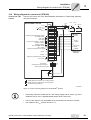
Wiring diagram, size 4 (TPS10A160)
Power section,
size 4
Connect the power section of the MOVITRANS® TPS10A160 stationary converter as
follows:
Vertical installation
Horizontal installation
L1
L2
L3
PE
F11/F12/F13
K11
(AC-3)
쵰 L1 L2 L3
NF...
쵰 L1' L2' L3'
[4]
쵰
1
2
7
3
L1 L2 L3
X1:
8
쵰
-UZ +UZ PE
X4:
MOVITRANS® TPS10A
X2:
N.C. G1 G2
-I
+I
4
6
9
5
MOVITRANS® TPS10A
X3:
N.C. PE
X2:
N.C. G1 G2
-I
+I
4
6
9
쵰
5
X3:
N.C. PE
쵰
HD...
[3]
A
IG
4
IG
5
6
9
N.C. G1 G2
X2:
-I
+I
쵰
N.C. PE
X3:
MOVITRANS® TAS10A
IL
[1]
5
6
9
쵰
N.C. G1 G2
X2:
-I
+I
N.C. PE
X3:
4
MOVITRANS® TAS10A
N.C. LI2 LA2 PE
N.C. LA1 LI1
B
n=5
IL
N.C. LI2 LA2 PE
N.C. LA1 LI1
쵰
쵰
[2]
[2]
Figure 8: Power section wiring diagram for MOVITRANS® TPS10A160
[1]
[2]
[3]
[4]
Twisted cables
Short-circuit hoop (for startup of TPS10A160 without connected line cables)
Connection conductor rail
Shielded cables
A
B
Version A (TAS10A160 connected to TPS10A160 using connection conductor rails)
Version B (TAS10A160 connected to TPS10A160 using twisted cables)
Operating Instructions – MOVITRANS® TPS10A Stationary Converters
55528AEN
17
Installation
Wiring diagram, size 4 (TPS10A160)
3
Versions
The TAS10A160 transformer module can be connected to the TPS10A160 stationary
converter using version A or B:
Version A
With this version, use standardized connection conductor rails to connect the
TAS10A160 transformer module to the TPS10A160 stationary converter. The rails are
included in the delivery scope of the TAS10A160 transformer module.
The following figure shows the preferred installation (vertically on top of one another)
and the connection of the units using conductor rails:
[1]
[4]
[2]
[3]
Figure 9: Connection conductor rails for MOVITRANS® TPS10A160 and TAS10A160
[1]
[2]
[3]
[4]
55306AXX
MOVITRANS® TPS10A160 stationary converter
Connection conductor rails
MOVITRANS® TAS10A160 transformer module
Connection conductor rails (detail view)
For more information on this topic, refer to the "MOVITRANS® TAS10A Transformer
Module" operating instructions.
Version B
18
With this version, you use twisted cables and connect the output choke HD003 at output
X2:G1/G2 to link the TAS10A160 transformer module to the TPS10A160 stationary
converter.
Output choke
HD003
Part number
813 558 4
Inside diameter d
88 mm (4.46 in)
For line cross sections
≥ 16 mm2 (AWG 6)
Operating Instructions – MOVITRANS® TPS10A Stationary Converters
Installation
Wiring diagram for control unit (TPS10A)
3
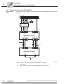
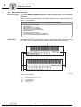
3.10 Wiring diagram for control unit (TPS10A)
Connect the control unit of the MOVITRANS® TPS10A040 or TPS10A160 stationary
converter as follows:
MOVITRANS® TPS10A
+10 V
IL 1
+
-
R11
X10:
-10 V
Reference potential analog signals
/Controller inhibit
/Ext. fault
Auto reset
Current control mode 1 / mode 2
Setpoint mode A
Setpoint mode B
Ref. X10:DIØØ...DIØ5
+24 V output
Reference potential binary signals
REF1
AI11
REF2
AI12
AGND
DIØØ
DIØ1
DIØ2
DIØ3
DIØ4
DIØ5
DCOM
VO24
DGND
/Fault
DOØ2
Ready
DOØØ
Reference potential binary signals
+24 V input
DGND
VI24
1
2
3
4
5
6
7
8
9
10
11
12
13
14
15
16
17
18
19
20
21
22
23
24
-10 V…+10 V
-40…+40 mA
I
U
X10:AI11/AI12
Control unit, size
2 and 4
Binary
inputs
Binary
outputs
Ref. binary
outputs
DGND
Higher-level
controller
ON OFF
S 12
S 11
Shield clamp
No function
Changeover I-signal U-signal
Factory setting is U-signal
AGND (Reference potential 10 V analog signals)
DGND (Reference potential 24 V binary signals)
Protective earth (shielding)
Figure 10: Control unit wiring diagram for MOVITRANS® TPS10A
55331AEN
•
If the binary inputs are set with the 24 V DC voltage supply X10:16 "VO24," you must
install the X10:15-X10:17 (DCOM-DGND) jumper at the control unit.
•
The S11 DIP switch is only accessible when the terminal unit has been removed.
•
The resistance R11min must be at least 4.7 kΩ.
Operating Instructions – MOVITRANS® TPS10A Stationary Converters
19
Installation
Wiring diagram for control unit (TPS10A)
3
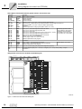
Description of terminal functions (power section and control unit)
Terminal
Function
X1: 1/2/3
X2: 4/5
X3: 6/9
X4: +UZ/-UZ
L1/L2/L3
G1/G2
–I/+I
+UZ/–UZ
Power supply connection
Gyrator connection
Current feedback
DC link connection
X10: 1
X10: 2/4
X10: 3
X10: 5/6/7
X10: 8
REF1
AI11/AI12
REF2
AGND
Reference voltage +10 V (max. 3 mA) for setpoint potentiometer
Setpoint input IL1 (differential input), switching between current/voltage input with S11
Reference voltage –10 V (max. 3 mA) for setpoint potentiometer
No function
Reference potential for analog signals (REF1, REF2, AI11, AI12)
X10: 9
X10: 10
X10: 11
X10: 12
X10: 13
X10: 14
X10: 15
X10: 16
X10: 17
DIØØ
DIØ1
DIØ2
DIØ3
DIØ4
DIØ5
DCOM
VO24
DGND
Binary input 1, with fixed assignment /Controller inhibit
Binary input 2, with fixed assignment /Ext. fault
Binary input 3, auto-reset
Binary input 4, with fixed assignment current control mode 1 / mode 2
Binary input 5, with fixed assignment setpoint mode A
Binary input 6, with fixed assignment setpoint mode B
Reference for binary inputs DIØØDIØ5
Auxiliary supply output +24 V (max. 200 mA)
Reference potential for binary signals
X10: 18/20/22
-
No function
X10: 19
X10: 21
X10: 23
DOØ2
DOØØ
DGND
Binary output 2, with fixed assignment /Fault
Binary output 0, with fixed assignment ready for operation
Reference potential for binary signals
X10: 24
VI24
Input +24 V power supply (only required for diagnostic purposes)
S11
S12
I↔U
-
AI11/AI12 toggle I signal (–40 ... +40 mA) ↔ V signal (–10 ...+10 V), factory setting: V signal
No function
The binary inputs are electrically isolated by optocouplers.
DCOM has to be connected
with DGND, if the binary inputs
are set with +24 V from VO24.
Load capacity: max. 50 mA
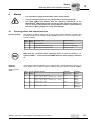
Assignment of electronics terminals and labeling tile
V1
V2
V3
REF1
REF2
DIØØ
DIØ2
DIØ4
DCOM
DGND
DOØ2
DOØØ
DGND
1
2
3
4
5
6
7
8
9 10
11 12
13 14
15 16
AI11
AI12
AGND
DIØ1
DIØ3
DIØ5
VO24
17 18
19 20
21 22
23 24
VI24
TPS10A X10
03880AXX
Figure 11: Electronics terminals and labeling tile
20
Operating Instructions – MOVITRANS® TPS10A Stationary Converters
Installation
Installing and removing a terminal unit
3.11
3
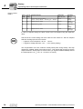
Installing and removing a terminal unit
Remove or mount terminal unit only with switched off unit (disconnected from
power supply)!
You can remove the entire terminal unit from the control module to facilitate installation
of the control cables and to easily replace the unit in case it has to be serviced. Proceed
as follows:
1. Open the flap on the terminal unit.
2. Loosen retaining screws A and B; they are captive screws and cannot fall out.
3. Remove the terminal unit from the control module.
ON
F
OF
2
S11
S1
3.
2.
A
1.
2.
B
03881AXX
Figure 12: Removing the terminal unit
Follow the instructions in reverse order when replacing the terminal unit.
Operating Instructions – MOVITRANS® TPS10A Stationary Converters
21
Installation
Connection of the serial interface option type USS21A (RS-232)
3
3.12 Connection of the serial interface option type USS21A (RS-232)
Part number
822 914 7
RS-232 interface
To connect a PC to the MOVITRANS® TPS10A option USS21A, use a commercial
shielded serial interface cable with a 1:1 connection assignment.
USS21A
PC COM 1-4
5
3
2
GND (ground)
5
TxD
3
2
RxD
max. 5 m (16.5 ft)
9-pin sub D connector (male)
9-pin sub D connector (female)
02399AEN
Figure 13: USS21A PC connection cable (1:1 connection assignment)
22
Operating Instructions – MOVITRANS® TPS10A Stationary Converters
I
Startup
Operating status and setpoint selection
4
0
4
4.1
Startup
•
It is essential to comply with the safety notes during startup!
•
Correct installation of the unit is a prerequisite for successful startup.
•
The SEW SHELL TPS software and the operating instructions of the
MOVITRANS® TAS10A transformer module are both required for startup. You
can use an R11 potentiometer for analog setpoint selection, as described in
the section "Wiring diagram for control unit TPS10A".
Operating status and setpoint selection
Operating status
The following operating statuses can be set for the TPS10A stationary converter with
the binary inputs X10:9 "/controller inhibit" (DIØØ) and X10:12 "Current control mode 1
/ mode 2" (DIØ3):
X10:9
(DIØØ)
X10:12
(DIØ3)
Operating status
Operation LED V1
"0"
-
Controller inhibit
Steady yellow light
"1"
"0"
Enable with current control mode 1
Flashing green-yellow light
"1"
"1"
Enable with current control mode 2
Steady green light
Make sure the "controller inhibit" operating status is active for startup (= "0"
signal on DIØØ → connect X10:9 with DGND) when the power supply is switched
on.
Setpoint
selection
Current control
mode 1
The following setpoint selections can be made at the TPS10A stationary converter via
binary inputs X10:13 "Setpoint mode A" (DIØ4) and X10:14 "Setpoint mode B" (DIØ5):
X10:13
(DIØ4)
X10:14
(DIØ5)
Setpoint selection
Ramp time
(Ref. 100 % IL)
Operation
LED V2
"0"
"0"
Analog input AI11/AI12 active
–10 V ... +10 V (–40 mA ... +40 mA) Ⳏ 0 ... 100 % IL
200 ms
Green
flashing
"1"
"0"
Analog input AI11/AI12 active
–10 V ... +10 V (–40 mA ... +40 mA) Ⳏ 0 ... 100 % IL
600 ms
Green
flashing
"0"
"1"
Setpoint 100 % IL fixed
200 ms
Steady
green light
"1"
"1"
Setpoint 100 % IL fixed
600 ms
Steady
green light
Operating Instructions – MOVITRANS® TPS10A Stationary Converters
23
4
I
Startup
Operating status and setpoint selection
0
Current control
mode 2
X10:13
(DIØ4)
X10:14
(DIØ5)
Setpoint selection
Ramp time
(Ref. 100 % IL)
Operation
LED V2
"0"
"0"
Analog input AI11/AI12 active
–10 V ... +10 V (–40 mA ... +40 mA) Ⳏ 0 ... 100 % IL
20 ms
Green
flashing
"1"
"0"
Setpoint 100 % IL fixed
100 ms
Steady
green light
"0"
"1"
Setpoint 50 % IL fixed
20 ms
Green-yellow
flashing
"1"
"1"
Setpoint 100 % IL fixed
20 ms
Steady
green light
In case of a setpoint change, the drive moves to the new setpoint using the respective
ramp.
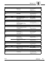
Check that the correct setting has been made for DIP switch S11 with the setpoint
selection "analog input AI11/AI12 active."
– I signal for current setpoints –40 mA ... +40 mA
– V signal for voltage setpoints –10 V ... +10 V (factory setting)
The compensation of the line conductor usually takes place during startup. This step
requires the variable setting of the load current IL. This means that you have to set the
setpoint selection "analog input AI11/AI12 active" ("0" signal on DIØ4 and DIØ5) and set
the initial setpoint 0 % IL (–10 V or –40 mA on AI11/AI12).
24
Operating Instructions – MOVITRANS® TPS10A Stationary Converters
Startup
Startup steps
I
4
0
4.2
Startup steps
Track
compensation
The inductance of the line conductor increases as the cable length increases.
This inductive reactance must be compensated by connecting compensation
capacitors in series (track compensation).
For more information on this topic, refer to the MOVITRANS® TAS10A transformer
module operating instructions in the sections "Wiring diagrams for line conductors on
TAS10A040" and "Wiring diagrams for line conductors on TAS10A160".
Step-by-step startup procedure
Perform the following steps to ensure successful startup:
1. Set an "0" signal on DIØØ "/controller inhibit.".
2. Set an "0" signal on DIØ4 and DIØ5 (setpoint selection "analog input AI11/AI12
active").
3. Set setpoint 0 % IL (–10 V or –40 mA on AI11/AI12).
4. Switch on the supply voltage.
5. Start the SEW SHELL TPS software.
6. From the main menu, choose [Connection] / [Connect].
7. In the [Select Interface] window select the PC interface (PC com) that the
MOVITRANS® TPS10A stationary converter is connected to.
8. From the main menu, choose [Startup] / [Compensation].
9. In the [Compensation] window, choose the line conductor current from the selection
list [Nominal line conductor current at 100 % setpoint] for the system in question.
The value corresponds to the rated output current of the MOVITRANS® TAS10A
transformer module and is used to calculate the absolute compensation error
correctly.
10.From the main menu, choose [Display Values] / [Process Values].
11.In the [Process Values] window, check the following values:
•
•
Fault Status = No fault
Output Current = 0.0 A
12.If required, change your settings as follows:
•
•
•
Ensure that a "1" signal is set at binary input "/Ext. fault" X10:10 (DIØ1) (Fault status = No external fault).
Set a "1" signal on DIØØ (Output stage = Enabled).
Set the desired setpoint with the voltage source (current source) on AI11/AI12:
–10 V ... +10 V (–40 mA ... +40 mA) Ⳏ 0 ... 100 % IL.
13.Carry out compensation of the line conductor:
•
•
Ensure that no real power can be transmitted while the measurement is taken.
Proceed as described in the flow diagram on the following page.
14.Choose the setpoint as required after compensation has been performed for the line
conductor.
For more information on this topic, refer to the section "Technical Data" in these
operating instructions or the sections "Technical Data" and "Compensation Capacitors" in the operating instructions for the MOVITRANS® TAS10A transformer
module.
Operating Instructions – MOVITRANS® TPS10A Stationary Converters
25
4
I
Startup
Startup steps
0
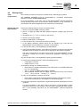
Flow diagram
Proceed as follows to determine the track compensation:
Provide complete track compensation set in accordance
with the BA MOVITRANS® TAS10A Transformer Module
Analog setpoint in TPS10A stationary converter should be
as large as possible without exceeding the
rated output current IG_N
Replace missing, used
compensation capacities
Read off the relative compensation error 쑶r
using the SEW SHELL TPS software
쑶r £ 30 % ?
Compensation completed
Yes
No
Read off the absolute compensation error 쑶X
using the SEW SHELL TPS software
Select compensation capacitor XC
according to XC £ 쑶X
Disconnect stationary converter from the power supply
Caution: Dangerous voltages can still be present up
to 10 minutes after the power has been disconnected!
Install compensation capacitor XC
in the TAS10A transformer module.
Read the installation notes in the MOVITRANS®
TAS10A transformer module operating instructions!
Switch on power
Figure 14: Track compensation for the MOVITRANS® TPS10A stationary converter
26
55212AEN
Operating Instructions – MOVITRANS® TPS10A Stationary Converters
Operation and Service
Operation displays
5
Operation and Service
5.1
Operation displays
Operation LEDs
5
Operating status, setpoint modes and error messages of the MOVITRANS® TPS10A
are indicated by the three-color (green/yellow/red) LEDs V1, V2 and V3.
V1
V2
V3
03883AXX
Figure 15: Operation LEDs V1, V2 and V3
V1: Operating
status
V2: Setpoint
specification
The operation LED V1 indicates the operating status of the unit.
V1 color
Operating status
Description
-
OFF
No voltage
No supply voltage and no 24 VDC backup voltage.
Yellow
Steady
light
Output stage inhibit
Unit ready but output stage inhibit active (DIØØ
= "0").
Yellowgreen
Flashing
Enable with current control
mode 1
Output stage enabled, current control mode 1
active (DIØØ = "1" and DIØ3 = "0").
Green
Steady
light
Enable with current control
Mode 2
Output stage enabled, current control mode 2
active (DIØØ = "1" and DIØ3 = "1").
Red
Steady
light
System error
Fault triggers output stage inhibit
The operation LED V2 indicates which setpoint selection is active:
V2 color
Setpoint selection
Description
–10...+10 V (–40 ... +40 mA) = 0...100 % IL
Green
Flashing
Analog input AI11/AI12 active
Yellowgreen
Flashing
50 % IL fixed value
Green
Steady
light
Fixed setpoint selection
100 % IL fixed value
Operating Instructions – MOVITRANS® TPS10A Stationary Converters
27
Operation and Service
Operation displays
5
V3: Fault messages
Color V3
Red
The operation LED V3 displays the following fault message if a fault occurs (V1 = red):
Fault message
and response
Steady
light
Over-current
Output stage
inhibit
X10:21
(DOØØ:
Ready)
X10:19
(DOØ2:
/Fault)
"0"
"0"
Cause
Action
–
–
–
–
Rectify the short circuit
Connect the correct TAS
–
Note the wiring diagrams in
the TAS operating instructions
Use a short-circuit hoop
Consult SEW Service
–
Short circuit on output
Gyrator impedance is too
small
TAS output open
–
Faulty output stage
–
–
Red
Flashing
Overtemperature
Output stage
inhibit
"0"
"0"
Thermal overload of unit
Reduce load and/or ensure adequate cooling.
Yellow/re
d
Flashing
External fault
(DIØ1 = "0")
Output stage
inhibit
"0"
"0"
External fault signal read in
via DIØ1.
Remedy external fault and make
sure that DIØ1 = "1".
Yellow
Steady
light
VZ undervoltage
Fault message
only
No output stage
inhibit
"1"
"0"
–
Power supply voltage too
low
–
–
Voltage drop too large on
power supply system line
–
Phase fault of power supply system line (fuse)
–
–
28
Connect to correct supply voltage (400/500 V)
Design power supply system
line so that the voltage drop is
relatively small
Check power supply system
line and fuses
Operating Instructions – MOVITRANS® TPS10A Stationary Converters
Operation and Service
Fault reset
5.2
5
Fault reset
Fault reset
Proceed as follows:
•
Remove the cause of the fault.
•
Carry out the edge change "1"→"0" at the binary input X10:9 DIØØ to trigger a reset.
or
•
Carry out the edge change "1"→"0" at the binary input X10:11 DIØ2 to reset the
faults.
The unit is now ready for operation again.
5.3
Auto reset function
Important:
The auto reset function must not be used in systems where the automatic restart
represents a risk of injury to persons or damage to equipment!
Function description
The auto reset function of the MOVITRANS® TPS10A stationary converter offers the option of resetting faults automatically when they occur on the unit.
The following faults can be reset:
Switching on/off
Auto reset
•
"Overcurrent"
•
"External fault"
•
"Overtemperature"
The auto reset function is switched on and off via binary input DIØ2:
X10:11 (DIØ2)
Auto reset function
"0"
Off
"1"
On
When an error occurs, the auto reset function resets the system automatically after a
fixed time of 50 ms (restart time). A maximum of three successive faults can be reset.
Further auto resets are only possible when a fault reset, as described in the "Fault reset"
section, has been performed.
Operating Instructions – MOVITRANS® TPS10A Stationary Converters
29
Operation and Service
Overload capacity
5
5.4
Overload capacity
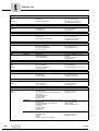
Continuous
output current
The MOVITRANS® TPS10A stationary converters calculate the load on the inverter output stage permanently (unit utilization). They can output the maximum possible power
in any operating status. The permitted continuous output current depends on the ambient temperature, heat sink temperature, supply voltage. If the load on the stationary converter is higher than permitted, the unit outputs the fault message "Overcurrent" (output
stage inhibit) and switches off immediately.
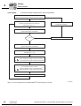
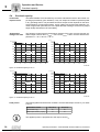
Temperature
change over time
The following charts show the temperature changes of the units over time and the permitted output currents when Vmains = 400 V and Vmains = 500 V and the ambient temperatures TU = 25 °C and TU = 40 °C.
% I G_N
% I G_N
150
140
150
140
120
120
100
100
80
80
400 V / 40 °C
60
60
40
40
20
20
t
0
0
1T
2T
3T
4T
5T
500 V / 40 °C
t
0
6T
0
1T
2T
3T
4T
5T
6T
54762AXX
Figure 16: Overload capacity at 40 °C
% I G_N
% I G_N
150
140
150
140
120
120
100
100
80
80
400 V / 25 °C
60
60
40
40
20
20
t
0
0
1T
2T
3T
4T
5T
500 V / 25 °C
t
0
6T
0
1T
2T
3T
4T
5T
6T
54763AXX
Figure 17: Overload capacity at 25 °C
Load period
The following table shows the time constant T and the rated output current IG_N for sizes
2 and 4:
MOVITRANS® TPS10A
040 (size 2)
160 (size 4)
Time constant T [s]
50
80
Rated output current IG_N [Aeff]
10
40
The apparent power is proportional to the output current IG.
30
Operating Instructions – MOVITRANS® TPS10A Stationary Converters
Operation and Service
Cut-off limits
5.5
5
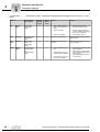
Cut-off limits
Cut-off limits
The following table shows the load capacity of the units:
Area
Heat sink temperatureϑ
Load capacity
1
0 °C ... 60 °C
The maximum load is 1.8 x IG_N.
2
60 °C ... 90 °C
The maximum load is reduced in linear form to 1.2 x IG_limit.
3
>90 °C
Unit switches off due to overtemperature (output stage inhibit).
When the unit output current IG exceeds the maximum possible load, the unit switches
off due to overcurrent (output stage inhibit).
Operating Instructions – MOVITRANS® TPS10A Stationary Converters
31
Operation and Service
Electronics service
5
5.6
Electronics service
Send in for repair
Contact the SEW-EURODRIVE Electronics Service in Bruchsal if a fault cannot be
rectified.
When contacting the electronics service, please always quote the digits of the service
code (→ service label).
Provide the following information when sending the unit in for repair:
–
–
–
–
–
–
–
–
–
Service label
Serial number (→ nameplate)
Type designation
Service code (→ service label)
Brief description of the application
Connected load (gyrator impedance)
Nature of the error
Accompanying circumstances
Your own presumption of what has happened
Any unusual events preceding the problem, etc.
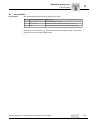
The MOVITRANS® TPS10A units have a service label for the power section and one for
the control unit. They are attached to the side of the unit next to the nameplate.
1
TPS 1
2
3
4
5
51421AXX
Figure 18: Service label
[1]
[2]
[3]
[4]
[5]
32
Service label for the control unit
Service label for the power section
Type designation
Component / part
Service code
Operating Instructions – MOVITRANS® TPS10A Stationary Converters
Technical Data
General information
6
Technical Data
6.1
General information
kVA
i
f
n
6
P Hz
The following table contains the technical data that applies to all MOVITRANS® TPS10A
stationary converters regardless of the size and power rating.
MOVITRANS® TPS10A
All sizes
Interference immunity
Meets EN 61800-3
Interference emission with EMC-compliant installation
Class A limit according to EN 55011 and EN 55014, meets
EN 61800-3
ϑ
Ambient temperature
Climate class
0 °C... +40 °C
EN 60721-3-3, class 3K3
Storage and shipping temperature1) ϑL
–25 °C ... +75 °C (EN 60721-3-3, class 3K3)
Enclosure
IP20
IP00, IP10 with installed touch guard
size 2 (TPS10A040)
size 4 (TPS10A160)
Pollution class
2 according to IEC 60664-1 (VDE 0110-1)
Operating mode
DB (EN 60149-1-1 and 1-3)
Installation altitude
h ≤ 1000 m (3300 ft)
IG_N reduction: 1 % per 100 m (330 ft)
of 1000 m (3300 ft) to max. 2000 m (6600 ft)
Resistance to vibration
Fulfills EN 50178
Relative humidity
≤ 95 %, no moisture condensation
1) For long-term storage, connect to power supply every two (2) years for at least 5 minutes, otherwise the
unit's service life may be shortened.
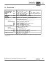
6.2
Line filter
B
L
H
X
R
Y
50462AXX
Figure 19: Line filter
Type
Part number
Lmax
[mm]
Hmax
[mm]
Bmax
[mm]
X
[mm]
Y
[mm]
R
[mm]
Terminal
[mm2]
Ground stud
Current
[A]
NF 014-503
827 116 X
225
80
50
20
210
5.5
4
M5
9
NF 035-503
827 128 3
275
100
60
30
255
5.5
10
M5
35
Operating Instructions – MOVITRANS® TPS10A Stationary Converters
33
kVA
6
i
6.3
f
n
Technical Data
Unit data
P Hz
Unit data
MOVITRANS® TPS10A
TPS10A040-NF0-503-1
TPS10A160-NF0-503-1
Part number
826 979 3
826 980 7
Input
Supply voltage
Vmains
380 VAC – 10 % ... 500 VAC + 10 %
Mains frequency
fmains
50 Hz ... 60 Hz 5 %
Rated mains current
(at Vmains = 3 × 400 VAC)
Imains
6.0 AAC
Rated output power
PN
4 kW
16 kW
24.0 AAC
Output
Rated output current
IG_N
10 AAC
40 AAC
Load current
IL
7.5 AAC
30.0 AAC
Rated output voltage
UA_N
400 VAC
Output frequency
fA
25 kHz
Gyrator impedance
XG
53.3 Ω
13.3 Ω
General
Power loss at IG_N
PV
Cooling air consumption
Mass
Dimensions
34
W×H×T
300 W
1800 W
80 m3/h (48 ft3/min)
360 m3/h (216 ft3/min)
5.9 kg (12.98 lb)
26.3 kg (57.86 lb)
130 × 335 × 207 mm
(5.12 × 13.19 × 8.15 in)
280 × 522 × 227 mm
(11.02 × 20.55 × 8.94 in)
Operating Instructions – MOVITRANS® TPS10A Stationary Converters
Technical Data
Electronics data
6.4
kVA
i
f
n
6
P Hz
Electronics data
MOVITRANS® TPS10A
General electronics data
Voltage supply
for setpoint potentiometer
X10:1
X10:3
REF1: +10 V +5 % / –0 %, Imax = 3 mA
REF2: –10 V +0 % / –5 %, Imax = 3 mA
Reference voltages for setpoint potentiometer
Setpoint input IL1X10:2
AI11/AI12
(differential input)
X10:4
IL1 = –10 V ... +10 V Ⳏ 0 ... 100 % IL
Resolution: 10-bit, sampling time: 800 µs
Ri = 40 kΩ (external voltage supply)
Ri = 20 kΩ (supply from X10:1/X10:3)
IL1 = –40 ... +40 mA Ⳏ 0 ... 100 % IL
Resolution: 10-bit, sampling time: 800 µs
Ri = 250 Ω
Auxiliary supply
output VO241)
X10:16
V = 24 VDC, current carrying capacity: Imax = 200 mA
External voltage
supply VI241)
X10:24
VN = 24 VDC –15 % / +20 % (range 19.2...30 VDC) according to EN 61131-2
Binary inputs DIØØDIØ5
Signal level
Control functions X10:9
X10:10
X10:11
X10:12
X10:13
X10:14
Binary outputs DOØØ and DOØ21)
Signal level
Control functions X10:19
X10:21
Reference terminals
X10:8
X10:17/X10:23
X10:15
Permitted line cross section
Isolated via optocoupler (EN 61131-2), Ri ≈ 3.0 kΩ, IE ≈ 10 mA
PLC compatible, sampling time: 400 µs
+13 ... +30 V = "1" = Contact closed according to EN 61131-2
–3 ... +5 V
= "0" = Contact open
DIØØ: With fixed assignment /controller inhibit
DIØ1: With fixed assignment /Ext. fault
DIØ2: With fixed assignment Auto reset
DIØ3: With fixed assignment Current control mode 1 / mode 2
DIØ4: With fixed assignment Setpoint mode A
DIØ5: With fixed assignment Setpoint mode B
PLC compatible (EN 61131-2), response time: 400 µs
Important: Do not apply external voltage!
Imax = 50 mA (short-circuit proof)
"0" = 0 V, "1" = 24 V
DOØ2: With fixed assignment /Fault
DOØØ: With fixed assignment Ready for operation
AGND: Reference potential for analog signals (AI11, AI12, REF1, REF2)
DGND: Reference potential for binary signals
DCOM: Reference for binary inputs DIØØ ... DIØ5
Single core: 0.20 ... 1.5 mm2 (AWG24...16)
Double core: 0.20 ... 1 mm2 (AWG24...17)
1) The unit provides a current of Imax = 400 mA for 24 VDC outputs X10:16 (VO24), X10:19 (DOØ2) and X10:21 (DOØØ). An external 24
VDC supply (support voltage) can be connected so that the electronic components remain ready for operation even in case of a power
supply interruption.
Operating Instructions – MOVITRANS® TPS10A Stationary Converters
35
kVA
6
i
6.5
f
n
Technical Data
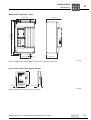
Dimensions
P Hz
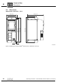
Dimensions
MOVITRANS® TPS10A040 – Size 2
130 (5.12)
207 (8.15)
120 (4.72)
335 (13.19)
315 (12.40)
300 (11.81)
105 (4.13)
6.5 (0.26)
Figure 20: Dimensions for MOVITRANS® TPS10A size 2, dimensions in mm (in)
36
54742AXX
Operating Instructions – MOVITRANS® TPS10A Stationary Converters
Technical Data
Dimensions
kVA
i
f
n
6
P Hz
MOVITRANS® TPS10A160 – Size 4
227 (8.94)
502 (19.76)
522 (20.55)
280 (11.02)
140 (5.51)
7
(0.28)
160 (6.30)
Figure 21: Dimensions for MOVITRANS® TPS10A size 4, dimensions in mm (in)
54743AXX
0V5 - +
RS485
RS232
1.5 (0.06)
85 (3.35)
120 (4.72)
Serial interface option type USS21A (RS-232)
28.5 (1.12)
01003BXX
Figure 22: Dimensions for option USS21A, in mm (in)
Operating Instructions – MOVITRANS® TPS10A Stationary Converters
37
7
Index
7
Index
A
Assignment of the electronics terminals .............20
Auto reset function ..............................................29
C
Connection
Control unit, size 2 and 4 (TPS10A) .............19
Power section, size 2 (TPS10A040) .............16
Power section, size 4 (TPS10A160) .............17
Serial interface type USS21A .......................22
Size 4 versions (TAS10A160) ......................18
Cut-off limits ........................................................31
D
Description of the terminal functions ...................20
Designated use .....................................................4
Dimensions
Serial interface USS21A ...............................37
Size 2 (TPS10A040) .....................................36
Size 4 (TPS10A160) .....................................37
E
Electronics data ..................................................35
Electronics service ..............................................32
F
Fault reset ...........................................................29
I
Installation
Notes ............................................................12
UL compliant .................................................14
L
Load period .........................................................30
N
Nameplate .............................................................8
O
Operation displays ..............................................27
Operation LEDs ..................................................27
Operational environment .......................................5
Overload capacity
Load period ...................................................30
Temperature change over time ....................30
Temperature ranges .....................................31
38
S
Safety notes ......................................................... 4
Installation and startup ................................... 6
Operation and service .................................... 6
Scope of delivery .................................................. 8
Serial interface USS21A .............................. 11, 37
Service
Auto reset function ....................................... 29
Cut-off limits ................................................. 31
Fault reset .................................................... 29
Operation displays ....................................... 27
Operation LEDs ........................................... 27
Overload capacity ........................................ 30
Repair .......................................................... 32
Service label ................................................ 32
Startup
Flow diagram ............................................... 26
Operating status .......................................... 23
Setpoint selection ........................................ 23
Step-by-step ................................................ 25
Track compensation .................................... 25
T
Technical data
Dimensions .................................................. 36
Electronics ................................................... 35
General information ..................................... 33
Line filter ...................................................... 33
Unit data ...................................................... 34
Temperature change over time .......................... 30
Temperature ranges ........................................... 31
Terminal description ........................................... 20
Touch guard ....................................................... 15
Track compensation ........................................... 25
U
UL compliant installation .................................... 14
Unit design
Size 2 (TPS10A040) ...................................... 9
Size 4 (TPS10A160) .................................... 10
Unit designation ................................................... 7
USS21A serial interface option .......................... 11
W
Warning notes ...................................................... 4
Waste disposal ..................................................... 5
Operating Instructions – MOVITRANS® TPS10A Stationary Converters
Address List
Address List
Germany
Headquarters
Production
Sales
Bruchsal
SEW-EURODRIVE GmbH & Co KG
Ernst-Blickle-Straße 42
D-76646 Bruchsal
P.O. Box
Postfach 3023 · D-76642 Bruchsal
Tel. +49 7251 75-0
Fax +49 7251 75-1970
http://www.sew-eurodrive.de
[email protected]
Service
Competence Center
Central
Gear units /
Motors
SEW-EURODRIVE GmbH & Co KG
Ernst-Blickle-Straße 1
D-76676 Graben-Neudorf
Tel. +49 7251 75-1710
Fax +49 7251 75-1711
[email protected]
Central
Electronics
SEW-EURODRIVE GmbH & Co KG
Ernst-Blickle-Straße 42
D-76646 Bruchsal
Tel. +49 7251 75-1780
Fax +49 7251 75-1769
[email protected]
North
SEW-EURODRIVE GmbH & Co KG
Alte Ricklinger Straße 40-42
D-30823 Garbsen (near Hannover)
Tel. +49 5137 8798-30
Fax +49 5137 8798-55
[email protected]
East
SEW-EURODRIVE GmbH & Co KG
Dänkritzer Weg 1
D-08393 Meerane (near Zwickau)
Tel. +49 3764 7606-0
Fax +49 3764 7606-30
[email protected]
South
SEW-EURODRIVE GmbH & Co KG
Domagkstraße 5
D-85551 Kirchheim (near München)
Tel. +49 89 909552-10
Fax +49 89 909552-50
[email protected]
West
SEW-EURODRIVE GmbH & Co KG
Siemensstraße 1
D-40764 Langenfeld (near Düsseldorf)
Tel. +49 2173 8507-30
Fax +49 2173 8507-55
[email protected]
Drive Service Hotline / 24 Hour Service
+49 180 5 SEWHELP
+49 180 5 7394357
Additional addresses for service in Germany provided on request!
France
Production
Sales
Service
Haguenau
SEW-USOCOME
48-54, route de Soufflenheim
B. P. 20185
F-67506 Haguenau Cedex
Tel. +33 3 88 73 67 00
Fax +33 3 88 73 66 00
http://www.usocome.com
[email protected]
Assembly
Sales
Service
Bordeaux
SEW-USOCOME
Parc d’activités de Magellan
62, avenue de Magellan - B. P. 182
F-33607 Pessac Cedex
Tel. +33 5 57 26 39 00
Fax +33 5 57 26 39 09
Lyon
SEW-USOCOME
Parc d’Affaires Roosevelt
Rue Jacques Tati
F-69120 Vaulx en Velin
Tel. +33 4 72 15 37 00
Fax +33 4 72 15 37 15
Paris
SEW-USOCOME
Zone industrielle
2, rue Denis Papin
F-77390 Verneuil I’Etang
Tel. +33 1 64 42 40 80
Fax +33 1 64 42 40 88
Additional addresses for service in France provided on request!
Algeria
Sales
Alger
Réducom
16, rue des Frères Zaghnoun
Bellevue El-Harrach
16200 Alger
Tel. +213 21 8222-84
Fax +213 21 8222-84
Buenos Aires
SEW EURODRIVE ARGENTINA S.A.
Centro Industrial Garin, Lote 35
Ruta Panamericana Km 37,5
1619 Garin
Tel. +54 3327 4572-84
Fax +54 3327 4572-21
[email protected]
Argentina
Assembly
Sales
Service
03/2005
35
Address List
Australia
Assembly
Sales
Service
Melbourne
SEW-EURODRIVE PTY. LTD.
27 Beverage Drive
Tullamarine, Victoria 3043
Tel. +61 3 9933-1000
Fax +61 3 9933-1003
http://www.sew-eurodrive.com.au
[email protected]
Sydney
SEW-EURODRIVE PTY. LTD.
9, Sleigh Place, Wetherill Park
New South Wales, 2164
Tel. +61 2 9725-9900
Fax +61 2 9725-9905
[email protected]
Wien
SEW-EURODRIVE Ges.m.b.H.
Richard-Strauss-Strasse 24
A-1230 Wien
Tel. +43 1 617 55 00-0
Fax +43 1 617 55 00-30
http://sew-eurodrive.at
[email protected]
Brüssel
SEW Caron-Vector S.A.
Avenue Eiffel 5
B-1300 Wavre
Tel. +32 10 231-311
Fax +32 10 231-336
http://www.caron-vector.be
[email protected]
Sao Paulo
SEW-EURODRIVE Brasil Ltda.
Avenida Amâncio Gaiolli, 50
Caixa Postal: 201-07111-970
Guarulhos/SP - Cep.: 07251-250
Tel. +55 11 6489-9133
Fax +55 11 6480-3328
http://www.sew.com.br
[email protected]
Austria
Assembly
Sales
Service
Belgium
Assembly
Sales
Service
Brazil
Production
Sales
Service
Additional addresses for service in Brazil provided on request!
Bulgaria
Sales
Sofia
BEVER-DRIVE GmbH
Bogdanovetz Str.1
BG-1606 Sofia
Tel. +359 2 9532565
Fax +359 2 9549345
[email protected]
Douala
Electro-Services
Rue Drouot Akwa
B.P. 2024
Douala
Tel. +237 4322-99
Fax +237 4277-03
Toronto
SEW-EURODRIVE CO. OF CANADA LTD.
210 Walker Drive
Bramalea, Ontario L6T3W1
Tel. +1 905 791-1553
Fax +1 905 791-2999
http://www.sew-eurodrive.ca
[email protected]
Vancouver
SEW-EURODRIVE CO. OF CANADA LTD.
7188 Honeyman Street
Delta. B.C. V4G 1 E2
Tel. +1 604 946-5535
Fax +1 604 946-2513
[email protected]
Montreal
SEW-EURODRIVE CO. OF CANADA LTD.
2555 Rue Leger Street
LaSalle, Quebec H8N 2V9
Tel. +1 514 367-1124
Fax +1 514 367-3677
[email protected]
Cameroon
Sales
Canada
Assembly
Sales
Service
Additional addresses for service in Canada provided on request!
Chile
Assembly
Sales
Service
Santiago de
Chile
SEW-EURODRIVE CHILE LTDA.
Las Encinas 1295
Parque Industrial Valle Grande
LAMPA
RCH-Santiago de Chile
P.O. Box
Casilla 23 Correo Quilicura - Santiago - Chile
Tel. +56 2 75770-00
Fax +56 2 75770-01
[email protected]
Tianjin
SEW-EURODRIVE (Tianjin) Co., Ltd.
No. 46, 7th Avenue, TEDA
Tianjin 300457
Tel. +86 22 25322612
Fax +86 22 25322611
[email protected]
http://www.sew.com.cn
China
Production
Assembly
Sales
Service
36
03/2005
Address List
China
Assembly
Sales
Service
Suzhou
SEW-EURODRIVE (Suzhou) Co., Ltd.
333, Suhong Middle Road
Suzhou Industrial Park
Jiangsu Province, 215021
P. R. China
Tel. +86 512 62581781
Fax +86 512 62581783
[email protected]
Bogotá
SEW-EURODRIVE COLOMBIA LTDA.
Calle 22 No. 132-60
Bodega 6, Manzana B
Santafé de Bogotá
Tel. +57 1 54750-50
Fax +57 1 54750-44
[email protected]
Zagreb
KOMPEKS d. o. o.
PIT Erdödy 4 II
HR 10 000 Zagreb
Tel. +385 1 4613-158
Fax +385 1 4613-158
[email protected]
Praha
SEW-EURODRIVE CZ S.R.O.
Business Centrum Praha
Luná 591
CZ-16000 Praha 6 - Vokovice
Tel. +420 a220121236
Fax +420 220121237
http://www.sew-eurodrive.cz
[email protected]
Kopenhagen
SEW-EURODRIVEA/S
Geminivej 28-30, P.O. Box 100
DK-2670 Greve
Tel. +45 43 9585-00
Fax +45 43 9585-09
http://www.sew-eurodrive.dk
[email protected]
Tallin
ALAS-KUUL AS
Paldiski mnt.125
EE 0006 Tallin
Tel. +372 6593230
Fax +372 6593231
[email protected]
Lahti
SEW-EURODRIVE OY
Vesimäentie 4
FIN-15860 Hollola 2
Tel. +358 201 589-300
Fax +358 3 780-6211
http://www.sew-eurodrive.fi
[email protected]
Libreville
Electro-Services
B.P. 1889
Libreville
Tel. +241 7340-11
Fax +241 7340-12
Normanton
SEW-EURODRIVE Ltd.
Beckbridge Industrial Estate
P.O. Box No.1
GB-Normanton, West- Yorkshire WF6 1QR
Tel. +44 1924 893-855
Fax +44 1924 893-702
http://www.sew-eurodrive.co.uk
[email protected]
Athen
Christ. Boznos & Son S.A.
12, Mavromichali Street
P.O. Box 80136, GR-18545 Piraeus
Tel. +30 2 1042 251-34
Fax +30 2 1042 251-59
http://www.boznos.gr
[email protected]
Hong Kong
SEW-EURODRIVE LTD.
Unit No. 801-806, 8th Floor
Hong Leong Industrial Complex
No. 4, Wang Kwong Road
Kowloon, Hong Kong
Tel. +852 2 7960477 + 79604654
Fax +852 2 7959129
[email protected]
Colombia
Assembly
Sales
Service
Croatia
Sales
Service
Czech Republic
Sales
Denmark
Assembly
Sales
Service
Estonia
Sales
Finland
Assembly
Sales
Service
Gabon
Sales
Great Britain
Assembly
Sales
Service
Greece
Sales
Service
Hong Kong
Assembly
Sales
Service
03/2005
37
Address List
Hungary
Sales
Service
Budapest
SEW-EURODRIVE Kft.
H-1037 Budapest
Kunigunda u. 18
Tel. +36 1 437 06-58
Fax +36 1 437 06-50
[email protected]
Assembly
Sales
Service
Baroda
SEW-EURODRIVE India Pvt. Ltd.
Plot No. 4, Gidc
Por Ramangamdi · Baroda - 391 243
Gujarat
Tel. +91 265 2831086
Fax +91 265 2831087
[email protected]
Technical Offices
Bangalore
SEW-EURODRIVE India Private Limited
308, Prestige Centre Point
7, Edward Road
Bangalore
Tel. +91 80 22266565
Fax +91 80 22266569
[email protected]
Mumbai
SEW-EURODRIVE India Private Limited
312 A, 3rd Floor, Acme Plaza
Andheri Kurla Road, Andheri (E)
Mumbai
Tel. +91 22 28348440
Fax +91 22 28217858
[email protected]
Dublin
Alperton Engineering Ltd.
48 Moyle Road
Dublin Industrial Estate
Glasnevin, Dublin 11
Tel. +353 1 830-6277
Fax +353 1 830-6458
Tel-Aviv
Liraz Handasa Ltd.
Ahofer Str 34B / 228
58858 Holon
Tel. +972 3 5599511
Fax +972 3 5599512
[email protected]
Milano
SEW-EURODRIVE di R. Blickle & Co.s.a.s.
Via Bernini,14
I-20020 Solaro (Milano)
Tel. +39 2 96 9801
Fax +39 2 96 799781
[email protected]
Abidjan
SICA
Ste industrielle et commerciale pour l’Afrique
165, Bld de Marseille
B.P. 2323, Abidjan 08
Tel. +225 2579-44
Fax +225 2584-36
Toyoda-cho
SEW-EURODRIVE JAPAN CO., LTD
250-1, Shimoman-no,
Toyoda-cho, Iwata gun
Shizuoka prefecture, 438-0818
Tel. +81 538 373811
Fax +81 538 373814
[email protected]
Ansan-City
SEW-EURODRIVE KOREA CO., LTD.
B 601-4, Banweol Industrial Estate
Unit 1048-4, Shingil-Dong
Ansan 425-120
Tel. +82 31 492-8051
Fax +82 31 492-8056
[email protected]
Riga
SIA Alas-Kuul
Katlakalna 11C
LV-1073 Riga
Tel. +371 7139386
Fax +371 7139386
[email protected]
Beirut
Gabriel Acar & Fils sarl
B. P. 80484
Bourj Hammoud, Beirut
Tel. +961 1 4947-86
+961 1 4982-72
+961 3 2745-39
Fax +961 1 4949-71
[email protected]
India
Ireland
Sales
Service
Israel
Sales
Italy
Assembly
Sales
Service
Ivory Coast
Sales
Japan
Assembly
Sales
Service
Korea
Assembly
Sales
Service
Latvia
Sales
Lebanon
Sales
38
03/2005
Address List
Lithuania
Sales
Alytus
UAB Irseva
Merkines g. 2A
LT-62252 Alytus
Tel. +370 315 79204
Fax +370 315 56175
[email protected]
www.sew-eurodrive.lt
Brüssel
CARON-VECTOR S.A.
Avenue Eiffel 5
B-1300 Wavre
Tel. +32 10 231-311
Fax +32 10 231-336
http://www.caron-vector.be
[email protected]
Johore
SEW-EURODRIVE SDN BHD
No. 95, Jalan Seroja 39, Taman Johor Jaya
81000 Johor Bahru, Johor
West Malaysia
Tel. +60 7 3549409
Fax +60 7 3541404
[email protected]
Queretaro
SEW-EURODRIVE, Sales and Distribution,
S. A. de C. V.
Privada Tequisquiapan No. 102
Parque Ind. Queretaro C. P. 76220
Queretaro, Mexico
Tel. +52 442 1030-300
Fax +52 442 1030-301
[email protected]
Casablanca
S. R. M.
Société de Réalisations Mécaniques
5, rue Emir Abdelkader
05 Casablanca
Tel. +212 2 6186-69 + 6186-70 + 618671
Fax +212 2 6215-88
[email protected]
Rotterdam
VECTOR Aandrijftechniek B.V.
Industrieweg 175
NL-3044 AS Rotterdam
Postbus 10085
NL-3004 AB Rotterdam
Tel. +31 10 4463-700
Fax +31 10 4155-552
http://www.vector.nu
[email protected]
Auckland
SEW-EURODRIVE NEW ZEALAND LTD.
P.O. Box 58-428
82 Greenmount drive
East Tamaki Auckland
Tel. +64 9 2745627
Fax +64 9 2740165
[email protected]
Christchurch
SEW-EURODRIVE NEW ZEALAND LTD.
10 Settlers Crescent, Ferrymead
Christchurch
Tel. +64 3 384-6251
Fax +64 3 384-6455
[email protected]
Moss
SEW-EURODRIVE A/S
Solgaard skog 71
N-1599 Moss
Tel. +47 69 241-020
Fax +47 69 241-040
[email protected]
Lima
SEW DEL PERU MOTORES REDUCTORES
S.A.C.
Los Calderos, 120-124
Urbanizacion Industrial Vulcano, ATE, Lima
Tel. +51 1 3495280
Fax +51 1 3493002
[email protected]
Lodz
SEW-EURODRIVE Polska Sp.z.o.o.
ul. Techniczna 5
PL-92-518 Lodz
Tel. +48 42 67710-90
Fax +48 42 67710-99
http://www.sew-eurodrive.pl
[email protected]
Luxembourg
Assembly
Sales
Service
Malaysia
Assembly
Sales
Service
Mexico
Assembly
Sales
Service
Morocco
Sales
Netherlands
Assembly
Sales
Service
New Zealand
Assembly
Sales
Service
Norway
Assembly
Sales
Service
Peru
Assembly
Sales
Service
Poland
Assembly
Sales
Service
03/2005
39
Address List
Portugal
Assembly
Sales
Service
Coimbra
SEW-EURODRIVE, LDA.
Apartado 15
P-3050-901 Mealhada
Tel. +351 231 20 9670
Fax +351 231 20 3685
http://www.sew-eurodrive.pt
[email protected]
Bucuresti
Sialco Trading SRL
str. Madrid nr.4
011785 Bucuresti
Tel. +40 21 230-1328
Fax +40 21 230-7170
[email protected]
St. Petersburg
ZAO SEW-EURODRIVE
P.O. Box 263
RUS-195220 St. Petersburg
Tel. +7 812 5357142 +812 5350430
Fax +7 812 5352287
http://www.sew-eurodrive.ru
[email protected]
Dakar
SENEMECA
Mécanique Générale
Km 8, Route de Rufisque
B.P. 3251, Dakar
Tel. +221 849 47-70
Fax +221 849 47-71
[email protected]
Beograd
DIPAR d.o.o.
Kajmakcalanska 54
SCG-11000 Beograd
Tel. +381 11 3088677 / +381 11
3088678
Fax +381 11 3809380
[email protected]
Singapore
SEW-EURODRIVE PTE. LTD.
No 9, Tuas Drive 2
Jurong Industrial Estate
Singapore 638644
Tel. +65 68621701
Fax +65 68612827
[email protected]
Sered
SEW-Eurodrive SK s.r.o.
Trnavska 920
SK-926 01 Sered
Tel. +421 31 7891311
Fax +421 31 7891312
[email protected]
Celje
Pakman - Pogonska Tehnika d.o.o.
UI. XIV. divizije 14
SLO – 3000 Celje
Tel. +386 3 490 83-20
Fax +386 3 490 83-21
[email protected]
Johannesburg
SEW-EURODRIVE (PROPRIETARY) LIMITED
Eurodrive House
Cnr. Adcock Ingram and Aerodrome Roads
Aeroton Ext. 2
Johannesburg 2013
P.O.Box 90004
Bertsham 2013
Tel. +27 11 248-7000
Fax +27 11 494-3104
[email protected]
Capetown
SEW-EURODRIVE (PROPRIETARY) LIMITED
Rainbow Park
Cnr. Racecourse & Omuramba Road
Montague Gardens
Cape Town
P.O.Box 36556
Chempet 7442
Cape Town
Tel. +27 21 552-9820
Fax +27 21 552-9830
Telex 576 062
[email protected]
Durban
SEW-EURODRIVE (PROPRIETARY) LIMITED
2 Monaceo Place
Pinetown
Durban
P.O. Box 10433, Ashwood 3605
Tel. +27 31 700-3451
Fax +27 31 700-3847
[email protected]
Romania
Sales
Service
Russia
Sales
Senegal
Sales
Serbia and Montenegro
Sales
Singapore
Assembly
Sales
Service
Slovakia
Sales
Slovenia
Sales
Service
South Africa
Assembly
Sales
Service
40
03/2005
Address List
Spain
Assembly
Sales
Service
Bilbao
SEW-EURODRIVE ESPAÑA, S.L.
Parque Tecnológico, Edificio, 302
E-48170 Zamudio (Vizcaya)
Tel. +34 9 4431 84-70
Fax +34 9 4431 84-71
[email protected]
Jönköping
SEW-EURODRIVE AB
Gnejsvägen 6-8
S-55303 Jönköping
Box 3100 S-55003 Jönköping
Tel. +46 36 3442-00
Fax +46 36 3442-80
http://www.sew-eurodrive.se
[email protected]
Basel
Alfred lmhof A.G.
Jurastrasse 10
CH-4142 Münchenstein bei Basel
Tel. +41 61 41717-17
Fax +41 61 41717-00
http://www.imhof-sew.ch
[email protected]
Chon Buri
SEW-EURODRIVE (Thailand) Ltd.
Bangpakong Industrial Park 2
700/456, Moo.7, Tambol Donhuaroh
Muang District
Chon Buri 20000
Tel. +66 38 454281
Fax +66 38 454288
[email protected]
Tunis
T. M.S. Technic Marketing Service
7, rue Ibn EI Heithem
Z.I. SMMT
2014 Mégrine Erriadh
Tel. +216 1 4340-64 + 1 4320-29
Fax +216 1 4329-76
Istanbul
SEW-EURODRIVE
Hareket Sistemleri Sirketi
Bagdat Cad. Koruma Cikmazi No. 3
TR-34846 Maltepe ISTANBUL
Tel. +90 216 4419163 + 216 4419164 +
216 3838014
Fax +90 216 3055867
[email protected]
Production
Assembly
Sales
Service
Greenville
SEW-EURODRIVE INC.
1295 Old Spartanburg Highway
P.O. Box 518
Lyman, S.C. 29365
Tel. +1 864 439-7537
Fax Sales +1 864 439-7830
Fax Manuf. +1 864 439-9948
Fax Ass. +1 864 439-0566
Telex 805 550
http://www.seweurodrive.com
[email protected]
Assembly
Sales
Service
San Francisco
SEW-EURODRIVE INC.
30599 San Antonio St.
Hayward, California 94544-7101
Tel. +1 510 487-3560
Fax +1 510 487-6381
[email protected]
Philadelphia/PA
SEW-EURODRIVE INC.
Pureland Ind. Complex
2107 High Hill Road, P.O. Box 481
Bridgeport, New Jersey 08014
Tel. +1 856 467-2277
Fax +1 856 845-3179
[email protected]
Dayton
SEW-EURODRIVE INC.
2001 West Main Street
Troy, Ohio 45373
Tel. +1 937 335-0036
Fax +1 937 440-3799
[email protected]
Dallas
SEW-EURODRIVE INC.
3950 Platinum Way
Dallas, Texas 75237
Tel. +1 214 330-4824
Fax +1 214 330-4724
[email protected]
Sweden
Assembly
Sales
Service
Switzerland
Assembly
Sales
Service
Thailand
Assembly
Sales
Service
Tunisia
Sales
Turkey
Assembly
Sales
Service
USA
Additional addresses for service in the USA provided on request!
Venezuela
Assembly
Sales
Service
03/2005
Valencia
SEW-EURODRIVE Venezuela S.A.
Av. Norte Sur No. 3, Galpon 84-319
Zona Industrial Municipal Norte
Valencia, Estado Carabobo
Tel. +58 241 832-9804
Fax +58 241 838-6275
[email protected]
[email protected]
41
SEW-EURODRIVE – Driving the world
Gearmotors \ Industrial Gear Units \ Drive Electronics \ Drive Automation \ Services
How we’re driving the world
With people who
think fast and
develop the
future with you.
With a worldwide
service network that is
always close at hand.
With drives and controls
that automatically
improve your productivity.
With uncompromising
quality that reduces the
cost and complexity of
daily operations.
With comprehensive
knowledge in virtually
every branch of
industry today.
SEW-EURODRIVE
Driving the world
With a global presence
that offers responsive
and reliable solutions.
Anywhere.
With innovative
technology that solves
tomorrow’s problems
today.
With online information
and software updates,
via the Internet, available
around the clock.
SEW-EURODRIVE GmbH & Co KG
P.O. Box 3023 · D-76642 Bruchsal / Germany
Phone +49 7251 75-0 · Fax +49 7251 75-1970
[email protected]
→ www.sew-eurodrive.com