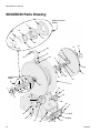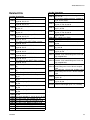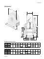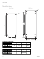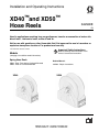
1
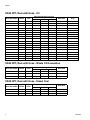
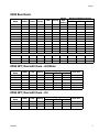
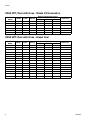
Installation and Operating Instructions XD40™and XD50™ Hose Reels 3A2990E EN Used in applications requiring long range dispense, transfer or evacuation of motor oils, diesel fuels*, lubricants, water, waste oil and air. Not for use with gasoline or other flammable fluid. Not approved for use in hazardous or explosive atmosphere locations. For professional use only. *less than 20% biofuel content Models Important Safety Instructions Read all warnings and instructions in this manual. Save these instructions. (see page 3 for addition model information) Spring Hose Reels XD40 - Floor, Truck-bed or Overhead Mounted XD50 - Floor or Truck-bed Mounted XD40 Related Manual: 332203 - Repair Instructions XD50 Table of Contents Table of Contents Models . . . . . . . . . . . . . . . . . . . . . . . . . . . . . . . . . . . 3 Warnings . . . . . . . . . . . . . . . . . . . . . . . . . . . . . . . . . 7 Installation . . . . . . . . . . . . . . . . . . . . . . . . . . . . . . . . 9 Installation Notes . . . . . . . . . . . . . . . . . . . . . . . . 9 Lifting Hose Reel . . . . . . . . . . . . . . . . . . . . . 9 Grounding . . . . . . . . . . . . . . . . . . . . . . . . . . . . . . 9 Typical Layout . . . . . . . . . . . . . . . . . . . . . . . . . . 10 Truck-bed or Floor . . . . . . . . . . . . . . . . . . . 10 Overhead: XD40 only . . . . . . . . . . . . . . . . . 10 Pressure Relief Procedure . . . . . . . . . . . . . . . . 11 Hose Installation . . . . . . . . . . . . . . . . . . . . . . . . 11 Adjusting Spring Tension . . . . . . . . . . . . . . . . . 14 Removing Spring Tension . . . . . . . . . . . . . . . . . 16 Inlet Orientation . . . . . . . . . . . . . . . . . . . . . . . . . 17 Bare Reels Only (without hose installed) . . 17 Reels with Hoses Installed . . . . . . . . . . . . . 17 Mounting Options . . . . . . . . . . . . . . . . . . . . . . . 19 All Mountings . . . . . . . . . . . . . . . . . . . . . . . 19 XD40 Models Only - Overhead Mounting . . 19 Hose Exit Configurations . . . . . . . . . . . . . . 20 Roller Support Arm Kits. . . . . . . . . . . . . . . . 20 Installing Inlet Hose . . . . . . . . . . . . . . . . . . . . . . 21 Flushing . . . . . . . . . . . . . . . . . . . . . . . . . . . 21 Operation . . . . . . . . . . . . . . . . . . . . . . . . . . . . . . . . 23 Hose Reel Retraction . . . . . . . . . . . . . . . . . 23 Troubleshooting . . . . . . . . . . . . . . . . . . . . . . . . . . . 24 Notes . . . . . . . . . . . . . . . . . . . . . . . . . . . . . . . . . . . . 25 XD40/XD50 Parts Drawing . . . . . . . . . . . . . . . . . . 26 XD40/XD50 Parts List . . . . . . . . . . . . . . . . . . . . . . 27 Related Kits . . . . . . . . . . . . . . . . . . . . . . . . . . . . 29 Technical Data . . . . . . . . . . . . . . . . . . . . . . . . . . . . 30 Dimensions . . . . . . . . . . . . . . . . . . . . . . . . . . . . 31 Mounting Hole Pattern . . . . . . . . . . . . . . . . 32 Table 1: Spring Tension Pre-turns . . . . . . . . . . . . 33 Air / Water Models . . . . . . . . . . . . . . . . . . . . . . . 33 Oil Models . . . . . . . . . . . . . . . . . . . . . . . . . . . . . 33 Waste Oil Evacuation Models . . . . . . . . . . . . . . 33 Fuel Models . . . . . . . . . . . . . . . . . . . . . . . . . . . 33 Graco XD40/XD50 Hose Reel Warranty . . . . . . . . 34 Graco Information . . . . . . . . . . . . . . . . . . . . . . . . . 34 2 3A2990E Models Models Understanding the Bare Reel Model Number Bare reels are assigned a model number. This number identifies the frame size, port size, spring and pressure associated with that reel. For example an XD4010DLP model is an XD Model hose reel, size 40 frame, 1 inch port, D spring, low pressure. • • • • XD Frame Size: 40 or 50 Port Size: 10 = 1 inch / 15 = 1.5 inch Spring Designation: A, B, C or D Pressure: LP - Low Pressure applications such as Air/Water, Fuel, and Waste Oil Evacuation typically under 300 psi (2.1 MPa, 21 bar) / MP - Medium Pressure applications such as Oil Dispense typically under 2000 psi (13.8 MPa, 138 bar) XD40 Bare Reels Maximum Working Pressure PSI MPa bar Bare Reel Model NPT Models BSPP Models BSPT Models Color Spring XD4010DLP 24P313 24P364 24P407 Blue D XD4010DLP 24P315 24P366 24P408 Yellow D 600 4.1 41 XD4010DLP 24P316 24P367 24P409 White D 600 4.1 41 XD4010CLP 24P317 24P368 24P410 Blue C 600 4.1 41 XD4010CLP 24P318 24P369 24P411 Yellow C 600 4.1 41 XD4010CLP 24P319 24P370 24P412 White C 600 4.1 41 XD4010CMP 24P320 24P371 24P413 Blue C 2000 13.8 138 XD4010CMP 24P322 24P372 24P414 Yellow C 2000 13.8 138 600 4.1 41 XD4010CMP 24P323 24P373 24P415 White C 2000 13.8 138 XD4010BMP 24R854 24R864 24R867 Blue B 2000 13.8 138 XD4010BMP 24R855 24R865 24R868 Yellow B 2000 13.8 138 XD4010BMP 24R856 24R866 24R869 White B 2000 13.8 138 XD4010AMP 24P324 24P374 24P416 Blue A 2000 13.8 138 XD4010AMP 24P325 24P375 24P417 Yellow A 2000 13.8 138 XD4010AMP 24P326 24P376 24P418 White A 2000 13.8 138 XD40 NPT, Reel with Hose - Air/Water Bare Reel Model Model XD4010DLP XD4010DLP Maximum Working Pressure PSI MPa bar Hose Size Color Spring 24P327 Blue D 300 2.1 21 1/2 inch x 100 ft. 24P328 Yellow D 300 2.1 21 1/2 inch x 100 ft. XD4010DLP 24P329 White D 300 2.1 21 1/2 inch x 100 ft. XD4010DLP 24P330 Blue D 300 2.1 21 3/4 inch x 75 ft. XD4010DLP 24P331 Yellow D 300 2.1 21 3/4 inch x 75 ft. XD4010DLP 24P332 White D 300 2.1 21 3/4 inch x 75 ft. XD4010CLP 24P333 Blue C 300 2.1 21 3/4 inch x 100 ft. XD4010CLP 24P334 Yellow C 300 2.1 21 3/4 inch x 100 ft. XD4010CLP 24P335 White C 300 2.1 21 3/4 inch x 100 ft. XD4010DLP 24P336 Blue D 300 2.1 21 1 inch x 50 ft. XD4010DLP 24P337 Yellow D 300 2.1 21 1 inch x 50 ft. XD4010DLP 24P338 White D 300 2.1 21 1 inch x 50 ft. 3A2990E 3 Models XD40 NPT, Reel with Hose - Oil Color Maximum Working Pressure PSI MPa bar Hose Size Bare Reel Model Model XD4010AMP 24P339 Blue 2000 13.8 138 1/2 inch x 100 ft. XD4010AMP 24P340 Yellow 2000 13.8 138 1/2 inch x 100 ft. Truck Mount Only XD4010AMP 24P341 White 2000 13.8 138 1/2 inch x 100 ft. XD4010CMP 24P342 Blue 1530 10.5 105 3/4 inch x 75 ft. X XD4010CMP 24P343 Yellow 1530 10.5 105 3/4 inch x 75 ft. X XD4010CMP 24P344 White 1530 10.5 105 3/4 inch x 75 ft. X XD4010BMP 24R857 Blue 1530 10.5 105 3/4 inch x 75 ft. XD4010BMP 24R859 Yellow 1530 10.5 105 3/4 inch x 75 ft. XD4010BMP 24R860 White 1530 10.5 105 3/4 inch x 75 ft. XD4010AMP 24P345 Blue 1530 10.5 105 3/4 inch x 100 ft. XD4010AMP 24P346 Yellow 1530 10.5 105 3/4 inch x 100 ft. XD4010AMP 24P347 White 1530 10.5 105 3/4 inch x 100 ft. XD4010CMP 24P348 Blue 1275 8.79 88 1 inch x 50 ft. X XD4010CMP 24P349 Yellow 1275 8.79 88 1 inch x 50 ft. X XD4010CMP 24P350 White 1275 8.79 88 1 inch x 50 ft. X XD4010BMP 24R861 Blue 1275 8.79 88 1 inch x 50 ft. XD4010BMP 24R862 Yellow 1275 8.79 88 1 inch x 50 ft. XD4010BMP 24R863 White 1275 8.79 88 1 inch x 50 ft. XD40 NPT, Reel with Hose - Waste Oil Evacuation Color Maximum Working Pressure PSI MPa bar Hose Size Bare Reel Model Model XD4010CLP 24P351 Blue 250 1.7 17 1 inch x 50 ft. XD4010CLP 24P352 Yellow 250 1.7 17 1 inch x 50 ft. XD4010CLP 24P353 White 250 1.7 17 1 inch x 50 ft. XD40 NPT, Reel with Hose - Diesel Fuel 4 Color Maximum Working Pressure PSI MPa bar Hose Size Bare Reel Model Model XD4010CLP 24P354 Blue 250 1.7 17 1 inch x 50 ft. XD4010CLP 24P355 Yellow 250 1.7 17 1 inch x 50 ft. XD4010CLP 24P356 White 250 1.7 17 1 inch x 50 ft. 3A2990E Models XD50 Bare Reels Bare Reel Model NPT Models BSPP Models BSPT Models Color Spring Porting Size (Inches) XD5010ALP 24P455 24P500 24P549 Blue A XD5010ALP 24P456 24P503 24P550 Yellow A XD5010ALP 24P457 24P504 24P551 White A 1 XD5015BLP 24P461 24P508 24P555 Blue B 1.5 XD5015BLP 24P462 24P509 24P556 Yellow B 1.5 600 4.1 41 XD5015BLP 24P463 24P510 24P558 White B 1.5 600 4.1 41 XD5010BLP 24P464 24P511 24P559 Blue B 1 600 4.1 41 XD5010BLP 24P465 24P512 24P560 Yellow B 1 600 4.1 41 XD5010BLP 24P466 24P513 24P561 White B 1 600 4.1 41 XD5015ALP 24P467 24P514 24P563 Blue A 1.5 600 4.1 41 XD5015ALP 24P468 24P515 24P564 Yellow A 1.5 600 4.1 41 XD5015ALP 24P469 24P516 24P565 White A 1.5 600 4.1 41 XD5010AMP 24P458 24P505 24P552 Blue A 1 2000 13.8 138 XD5010AMP 24P459 24P506 24P553 Yellow A 1 2000 13.8 138 XD5010AMP 24P460 24P507 24P554 White A 1 2000 13.8 138 Maximum Working Pressure PSI MPa bar 1 600 4.1 41 1 600 4.1 41 600 4.1 41 600 4.1 41 XD50 NPT, Reel with Hose - Air/Water Maximum Working Pressure PSI MPa bar Bare Reel Model Model Color Spring XD5010ALP 24P470 Blue A 300 2.1 XD5010ALP 24P471 Yellow A 300 XD5010ALP 24P472 White A 300 XD5010ALP 24P473 Blue A 300 XD5010ALP 24P474 Yellow A 300 2.1 21 1 inch x 100 ft. XD5010ALP 24P475 White A 300 2.1 21 1 inch x 100 ft. Hose Size 21 1 inch x 75 ft. 2.1 21 1 inch x 75 ft. 2.1 21 1 inch x 75 ft. 2.1 21 1 inch x 100 ft. XD50 NPT, Reel with Hose - Oil Maximum Working Pressure PSI MPa bar Bare Reel Model Model Color Spring XD5010AMP 24P476 Blue A XD5010AMP 24P477 Yellow A 1275 8.79 88 1 inch x 75 ft. XD5010AMP 24P478 White A 1275 8.79 88 1 inch x 75 ft. 3A2990E 1275 8.79 88 Hose Size 1 inch x 75 ft. 5 Models XD50 NPT, Reel with Hose - Waste Oil Evacuation Maximum Working Pressure PSI MPa bar Bare Reel Model Model XD5015BLP 24P479 Blue B 200 1.4 14 1.25 inch x 35 ft. XD5015BLP 24P480 Yellow B 200 1.4 14 1.25 inch x 35 ft. XD5015BLP 24P481 White B 200 1.4 14 1.25 inch x 35 ft. XD5015BLP 24P482 Blue B 200 1.4 14 1.25 inch x 50 ft. XD5015BLP 24P483 Yellow B 200 1.4 14 1.25 inch x 50 ft. XD5015BLP 24P484 White B 200 1.4 14 1.25 inch x 50 ft. Color Spring Hose Size XD50 NPT, Reel with Hose - Diesel Fuel 6 Maximum Working Pressure PSI MPa bar Bare Reel Model Model Color Spring XD5010BLP 24P485 Blue B 250 1.7 17 1 inch x 75 ft. XD5010BLP 24P486 Yellow B 250 1.7 17 1 inch x 75 ft. XD5010BLP 24P487 White B 250 1.7 17 1 inch x 75 ft. XD5010ALP 24P488 Blue A 250 1.7 17 1 inch x 100 ft. XD5010ALP 24P489 Yellow A 250 1.7 17 1 inch x 100 ft. XD5010ALP 24P490 White A 250 1.7 17 1 inch x 100 ft. XD5015BLP 24P491 Blue B 250 1.7 17 1.25 inch x 35 ft. XD5015BLP 24P492 Yellow B 250 1.7 17 1.25 inch x 35 ft. XD5015BLP 24P493 White B 250 1.7 17 1.25 inch x 35 ft. XD5015BLP 24P494 Blue B 250 1.7 17 1.25 inch x 50 ft. XD5015BLP 24P495 Yellow B 250 1.7 17 1.25 inch x 50 ft. XD5015BLP 24P496 White B 250 1.7 17 1.25 inch x 50 ft. XD5015ALP 24P497 Blue A 150 1.0 10 1.5 inch x 50 ft. XD5015ALP 24P498 Yellow A 150 1.0 10 1.5 inch x 50 ft. XD5015ALP 24P499 White A 150 1.0 10 1.5 inch x 50 ft. Hose Size 3A2990E Warnings Warnings The following warnings are for the setup, use, grounding, maintenance, and repair of this equipment. The exclamation point symbol alerts you to a general warning and the hazard symbols refer to procedure-specific risks. When these symbols appear in the body of this manual or on warning labels, refer back to these Warnings. Product-specific hazard symbols and warnings not covered in this section may appear throughout the body of this manual where applicable. WARNING WARNING FIRE AND EXPLOSION HAZARD When flammable fluids are present in the work area, such as gasoline and windshield wiper fluid, be aware that flammable fumes can ignite or explode. To help prevent fire and explosion: • Use equipment only in well ventilated area. • Eliminate all ignition sources, such as cigarettes and portable electric lamps. • Keep work area free of debris, including rags and spilled or open containers of solvent and gasoline. • Do not plug or unplug power cords or turn lights on or off when flammable fumes are present. • Ground all equipment in the work area. • Only use hoses that are compatible with the fluid you are dispensing. • Stop operation immediately if static sparking occurs or you feel a shock. Do not use equipment until you identify and correct the problem. • Keep a working fire extinguisher in the work area. + 3A2990E SKIN INJECTION HAZARD Pressurized fluid from dispensing device, hose leaks, or ruptured components will pierce skin. This may look like just a cut, but it is a serious injury that can result in amputation. Get immediate surgical treatment. • Do not point dispensing device at anyone or at any part of the body. • Do not put your hand over the fluid outlet. • Do not stop or deflect leaks with your hand, body, glove, or rag. • Follow the Pressure Relief Procedure when you stop dispensing and before cleaning, checking, or servicing equipment. • Tighten all fluid connections before operating the equipment. • Check hoses and couplings daily. Replace worn or damaged parts immediately. 7 Warnings WARNING WARNING EQUIPMENT MISUSE HAZARD Misuse can cause death or serious injury. • Do not operate the unit when fatigued or under the influence of drugs or alcohol. • Do not exceed the maximum working pressure or temperature rating of the lowest rated system component. See Technical Data in all equipment manuals. • Use fluids and solvents that are compatible with equipment wetted parts. See Technical Data in all equipment manuals. Read fluid and solvent manufacturer’s warnings. For complete information about your material, request MSDS from distributor or retailer. • Do not leave the work area while equipment is energized or under pressure. • Turn off all equipment and follow the Pressure Relief Procedure when equipment is not in use. • Check equipment daily. Repair or replace worn or damaged parts immediately with genuine manufacturer’s replacement parts only. • Do not alter or modify equipment. Alterations or modifications may void agency approvals and create safety hazards. • Make sure all equipment is rated and approved for the environment in which you are using it. • Use equipment only for its intended purpose. Call your distributor for information. • Route hoses and cables away from traffic areas, sharp edges, moving parts, and hot surfaces. • Do not kink or over bend hoses or use hoses to pull equipment. • Keep children and animals away from work area. • Comply with all applicable safety regulations. MOVING PARTS HAZARD Moving parts can pinch, cut or amputate fingers and other body parts. • Keep clear of moving parts. • Do not operate equipment with protective guards or covers removed. • Pressurized equipment can start without warning. Before checking, moving, or servicing equipment, follow the Pressure Relief Procedure and disconnect all power sources. TOXIC FLUID OR FUMES HAZARD Toxic fluids or fumes can cause serious injury or death if splashed in the eyes or on skin, inhaled, or swallowed. • Read MSDSs to know the specific hazards of the fluids you are using. • Store hazardous fluid in approved containers, and dispose of it according to applicable guidelines. PERSONAL PROTECTIVE EQUIPMENT Wear appropriate protective equipment when in the work area to help prevent serious injury, including eye injury, hearing loss, inhalation of toxic fumes, and burns. This protective equipment includes but is not limited to: • Protective eyewear, and hearing protection. • Respirators, protective clothing, and gloves as recommended by the fluid and solvent manufacturer 8 3A2990E Installation Installation Installation Notes • A flexible hose connection must be used between the hose reel inlet and the source of the supply to prevent possible misalignment and binding. • Maximum Recommended Installation Height: • XD40 - 15 feet (4.6 meters) (See FIG. 4, page 10) • XD4010CMP - 8 feet (2.4 meters) • XD50 - 8 feet (2.4 meters) Grounding The equipment must be bonded (grounded) to the truck. Grounding reduces the risk of static shock due to static build up on the equipment. Refer to your pump instruction manual for grounding instructions. Lifting Hose Reel Always use a hoist or other suitable lifting device to raise hose reel into position. Secure a lifting strap around spool as shown in FIG. 1. See Technical Data (page 30) for hose reel weights. FIG. 2 FIG. 1 3A2990E 9 Installation Typical Layout The installations shown in FIG. 3 and FIG. 4 are only a guide. Contact your Graco distributor for assistance in designing a system to suit your needs. Truck-bed or Floor Overhead: XD40 only A E C A F D E B B E C FIG. 3 Key: A B C D E To Pump Fluid Inlet Hose Reel Dispense Valve Mounting Channel D FIG. 4 Key: A B C D E F 10 15 feet (4.6 m) max installed height To Pump Fluid Inlet Hose Reel Dispense Valve Mounting Channel Fluid Shutoff Valve 3A2990E Installation Pressure Relief Procedure Hose Installation NOTE: The following procedure is NOT used to remove tension from the spring. See Removing Spring Tension (page 16) for this procedure. NOTE: The following instructions assume this is a first time hose installation on a new bare reel. For Hose Replacement instructions, see Repair Manual, Removing the Hose instructions. Follow the Pressure Relief Procedure whenever you see this symbol. This equipment stays pressurized until pressure is manually relieved. To help prevent serious injury from pressurized fluid, such as skin injection, splashing fluid and moving parts, follow the Pressure Relief Procedure when you stop dispensing and before cleaning, checking, or servicing the equipment. 1. Turn off power supply to fluid pump. 1. If the hose reel is not installed in a fixed location, use 2, large c-clamps (B) (one on the front and one on the back) to secure the hose reel to a flat surface (FIG. 5). Graco recommends placing a rag over the bottom roller and the back frame to protect these surfaces from damage when the c-clamps are tightened down. NOTICE The front c-clamp (B) should only be tightened enough to prevent the reel from moving. Overtightening this clamp could damage the bottom roller. 2. Isolate the supply pump fluid supply line. 3. Open the dispensing valve until pressure is fully relieved. If you suspect the dispensing valve or extension is clogged or that pressure has not been fully relieved after following the steps above, VERY SLOWLY loosen coupler or hose end coupling to relieve pressure gradually, then loosen completely. Clear the obstruction. (B) FIG. 5 2. Verify the spring is not under tension. If there is spring tension, follow Removing Spring Tension procedure provided on page 16. 3A2990E 11 Installation 3. For easier hose installation, Graco recommends removing the outlet (30) from the spool. To do this remove bolts (37) holding outlet to the spool (FIG. 6). 4. Apply pipe thread sealant or wrap PTFE tape around the threads of reducer (53) (if needed). Then install reducer (53) in the end of the outlet (FIG. 6). Use two wrenches on the flats, working in opposite directions, to securely tighten the reducer to the outlet fitting. NOTE: A reducer (53) is not required for all installations. It is only necessary if the hose diameter is smaller than the diameter of the outlet (30). 30 53 • Never allow the reel to spin freely. Doing so causes the spool to spin out of control, which could cause serious injury if you are hit by the hose. • Always wear heavy, non-slippery gloves when adjusting the spring tension to protect your hands from being cut on the hose reel. 6. Uncoil and extend hose. 7. Feed opposite end of the hose, through the rollers (a), then under the reel (b), and around the back (c) of the spool. 37 a FIG. 6: Low Pressure Outlet shown. Medium Pressure models use 6 bolts. 5. Install the ball stop (45) near the end of the hose using screws (46) and nuts (47). Tighten nuts until the outside edges of the stop contact each other (FIG. 7). c b FIG. 8 46 47 8. Apply pipe thread sealant or wrap hose threads with PTFE tape. 45 FIG. 7 12 3A2990E Installation 9. Attach end of the hose to the outlet (30) using two wrenches on the flats, working in opposite directions, to securely tighten the hose to the outlet fitting (FIG. 9). 13. Securely attach a c-clamp (A) to the reel spool as shown in FIG. 10 to help prevent the reel from unintentionally becoming unlatched and spinning freely. 30 FIG. 9 10. Place a piece of tape on the side of the reel flange as a visual reference point for counting reel rotations. 11. Pre-wind hose reel as needed to accommodate the length of hose you are installing. Refer to Table 1, Spring Tension and Pre-Turns, page 33 to determine the number of turns needed for your hose and reel model. A FIG. 10 14. Verify outlet o-ring (34) is in place on outlet (30). Apply a thin layer of grease (G) to o-ring as shown in FIG. 11. (G) 30 NOTE: Wind direction is determined by the direction the spool rotates when the hose is extended during operation. Never allow the reel to spin freely. Doing so causes the spool to spin out of control, which could cause serious injury if you are hit by the hose or dispense valve. 34 FIG. 11 12. Engage the latch. Listen for the loud click when the spool has latched. 3A2990E 13 Installation 15. Install outlet (30) to spool. Replace and tighten all bolts (37) securely. Torque bolts to 24 to 30 ft. pounds (32.54 to 40.67 N.m) (FIG. 12). NOTE: Adjusting Spring Tension If the hose cannot be pulled all the way out or if it does not retract all the way back onto the hose reel, you need to adjust the spring tension. • Low Pressure Models (shown in FIG. 12) use 4 bolts (37). • Medium Pressure Models (not shown) use 6 bolts (37). • Always use all bolts provided. 30 37 FIG. 12: Low Pressure Model Shown. 16. Remove c-clamp (A) (installed in Step 12, page 13). 17. Disengage latch by pulling on hose to release it. • Never allow the reel to spin freely. Doing so causes the spool to spin out of control, which could cause serious injury if you are hit by the hose. • Always wear heavy, non-slippery gloves when adjusting the spring tension to protect your hands from being cut on the hose reel. 1. If the hose reel has been in service, relieve pressure, page 11. 2. Pull the hose out far enough to engage the latch. NOTE: Listen for the loud click when the spool has latched. 3. Attach a c-clamp (A) to the reel spool as shown in FIG. 13 to help prevent the reel from unintentionally becoming unlatched and spinning freely. Always wear heavy, non-slippery gloves when adjusting the spring tension to protect your hands from being cut on the hose reel. 18. Use your hand to guide the hose as it rewinds onto the reel. 19. Adjust spring tension if needed. See Adjusting Spring Tension, page 14. (A) 20. Install dispense valve to end of hose. (A) FIG. 13 If a ball stop and dispensing device are NOT installed on the hose end, skip Step 4 and continue instructions with Step 5. 14 3A2990E Installation 4. Remove dispense valve, nuts (47), screws (46) and ball stop (45) from end of hose (FIG. 18). 9. Check the spring tension. When it is set correctly after pulling the hose completely off the spool it will retract fully. NOTICE 47 46 Always hold on to the hose while it is rewinding to avoid damage to the reel. 10. Repeat Steps 8 and 9 until you have the proper amount of spring tension. 45 NOTICE FIG. 14 5. Feed the loose end of the hose through the hose rollers and manually wrap and secure the hose onto the reel. Do not increase the spring tension so much that the spring winds up tightly before the hose is fully extended. A spring that is wound too tightly: • Stops the reel from rotating before the hose is fully extended, which puts excessive strain on the hose and reel spring. • Can cause the latch and ratchet to lock, making disengagement by pulling the hose impossible. 11. Rotate spool to engage latch to prevent spool rotation or unwinding. 12. Securely attach a c-clamp (A) to the reel spool as shown in FIG. 13 to help prevent the reel from unintentionally becoming unlatched and spinning freely. 13. Route end of the hose through the hose rollers (FIG. 16). FIG. 15 6. Place tape on the side of the reel flange as a visual reference point for counting reel rotations. 7. Remove c-clamp (A) installed in Step 3. 8. Rotate reel spool keeping the hose wrapped on the reel. NOTE: • Each rotation of the reel spool increases or decreases enough spring tension to retract or let out approximately 5 feet (1.5 m) of hose. - Wind spring, in one turn increments, tighter to increase tension. - Unwind spring, in one turn increments, to decrease spring tension. • Refer to the Table 1: Spring Tension and Preturns (page 33) to determine the number of spool rotations needed to correctly set the spring tension for your reel model and hose. 3A2990E FIG. 16 14. Reinstall ball stop and dispensing valve (FIG. 14). 15. Remove c-clamp (A). 16. Pressurize hose reel and reverify spring tension. 15 Installation Removing Spring Tension 4. Remove dispense valve, nuts (47), screws (46) and ball stop (45) from end of hose (FIG. 18). Cap end of hose (if needed) to prevent fluid spills. 1. If the hose reel has been in service, relieve pressure, page 11. Always wear heavy, non-slippery gloves when adjusting the spring tension to protect your hands from being cut on the hose reel. 2. Pull the hose out far enough to engage the latch. 47 46 45 FIG. 18 5. Feed loose end of hose through the hose rollers and manually wrap and secure hose onto reel (FIG. 19). NOTE: Listen for the loud click when the spool has latched. 3. Attach a c-clamp (A) to the reel spool as shown in FIG. 17 to help prevent the reel from unintentionally becoming unlatched and spinning freely. FIG. 19 6. Place a piece of tape on the side of the reel flange as a visual reference point for counting reel rotations. (A) FIG. 17 7. Remove c-clamp (A). 8. Rotate spool in the tightening direction to disengage latch. 9. Use your hands to unwind reel by rotating the spool in the opposite direction turned in step 8, until it the reel reaches a free state. Always keep at least one hand on the spool to prevent free-spool rotation. NOTE: Count the number of turns while unwinding the spool and record the number for use when retensioning the spring later. 16 3A2990E Installation Inlet Orientation 3. Rotate inlet (6) to desired location. • In all installations Graco recommends adjusting the orientation of the inlet prior to installing the hose reel. • If the hose reel is installed on a flat surface, such as a truck bed, the reel does not have to be removed from it’s service location to change the inlet orientation. • Inlet (6) is designed with a weep hole (a) (FIG. 20) to indicate a failed seal. NOTE: The inlet can be rotated and set to 6 possible positions. 4. Align shim (36) between inlet (6) and bearing retainer (35) (FIG. 21). 31 4a Bare Reels Only (without hose installed) 36 4b Never allow the reel to spin freely. Doing so causes the spool to spin out of control, which could cause serious injury. 6 4 FIG. 21 1. Before changing inlet orientation, verify the spring is not under tension by performing the Removing Spring Tension procedure, page 16. 31 4 5. First install the side 2 bolts (4a and 4b) as shown in FIG. 21through frame and inlet (6). Tighten bolts just enough to hold everything in place. 6. Then install the remaining four bolts (4). Hand tighten and then torque all bolts to 25 to 35 ft. lbs (33.9 to 47.45 N•m). Reels with Hoses Installed 36 1. Relieve pressure, page 11. a 2. Disconnect inlet hose from inlet fitting (6). 6 FIG. 20 2. Remove six bolts (4) (FIG. 20). NOTE: Never allow the reel to spin freely. Doing so causes the spool to spin out of control, which could cause serious injury if you are hit by the hose. • It is not necessary to remove inlet (6) to change it’s position. 3. Overhead or wall mounted hose reels must be removed from service and secured to a flat surface (B, FIG. 22) before changing the inlet orientation. • The shim (36) may move out of place behind the outlet when the bolts are removed. Do not lose this piece. It will be needed for reassembly after the outlet location is adjusted. NOTE: To secure hose reel to a flat surface use 2 large c-clamps (B) (one on the front and one on the back). Graco recommends placing a rag over the bottom roller and the back frame to protect these 3A2990E 17 Installation surfaces from damage when the c-clamps are tightened down. 31 4 NOTICE The front c-clamp (B) should only be tightened enough to prevent the reel from moving. Overtightening this clamp could damage the bottom roller. 36 6 FIG. 23 6. Remove six bolts (4). (A) (B) NOTE: The shim (36) may move out of place behind the outlet when the bolts are removed. Do not lose this piece. It will be needed for reassembly after the outlet location is adjusted. 7. Rotate inlet (6) to desired location. NOTE: The inlet can be rotated and set to 6 possible positions. 8. Align shim (36) between inlet (6) and bearing retainer (5). FIG. 22 6 4. The hose must be fully retracted before starting this procedure. Be sure the ball stop is in place to help prevent the reel from unintentionally spinning. 4a 4b 5 5. Engage latch. Securely attach a c-clamp (A) to the spool as shown in FIG. 22 to help prevent the reel from unintentionally spinning freely. 36 4 4 FIG. 24 18 3A2990E Installation 9. First install the top 2 bolts (4a and 4b), through the frame and inlet (6), as shown in FIG. 24. Tighten bolts just enough to hold everything in place. 10. Then install the remaining bolts (4). Hand tighten and then torque all bolts to 25 to 35 ft. lbs (33.9 to 47.45 N•m). XD40 Models Only - Overhead Mounting Use Graco Overhead Mounting Kit 237932 for mounting the hose reel base to an overhead I-beam. Contact your Graco distributor or Graco Customer Service for additional information about this kit. 11. Remove c-clamp. NOTICE Always hold on to the hose while it is rewinding to avoid damage to the reel. 12. If necessary, adjust spring tension. See Adjusting Spring Tension instructions, page 14. Mounting Options All Mountings NOTE: • Always use large flat washers with the bolts you use to mount the hose reel pedestal to any surface. • In overhead or wall mounted installations, if the inlet orientation requires adjustment, change the orientation of the inlet prior to installing the hose reel. See Inlet Orientation, page 17. • In overhead installations, the hose should be installed on the reel before you mount the reel. See Hose Installation, page 11, if the hose is not already installed on the reel. • To reduce the risk of injury when mounting a hose reel overhead, always use a lift truck. • Be sure the mounting surface is strong enough to support the reel, the weight of the lubricants and the stress caused by hard pulls on the service hoses. For the following Steps, refer to FIG. 26. 1. Install hose on reel prior to installation. See Hose Installation, page 11. 2. Verify spring tension is set correctly. See Adjusting Spring Tension, page 14. 3. Adjust inlet orientation if needed. See Inlet Orientation, page 17. 4. Install roller arm supports using Roller Arm Kit 24R076 (XD40) or 24R077 (XD50). Instructions for this procedure are provided in the Roller Arm Kit and should be used for this installation. 5. Select the reel mounting location. • For high ceilings, suspend a suitable support structure for the reels so the hoses will be long enough to reach the service area. • Do not exceed installation height of 15 ft. (4.57 m). 6. Position the hose reel so the mounting brackets (included in Kit 237932) are facing up. B C A FIG. 25: Overhead installation shown FIG. 26 3A2990E 19 Installation 7. Line up the 4 holes on the hose reel mounting base with the holes near the ends of the mounting brackets (A) (FIG. 26) and securely bolt the hose reel to the mounting brackets. Truck / Bench Hose Extending from Topside of Spool 8. Using a lift truck, raise the hose reel as close to the I-beam as possible. 9. Position adjustable clamps (C) of the mounting brackets on the flanges of the I-beam (B) (FIG. 26). Securely tighten clamps to 10 ft. lbs (13.5 N.m). 10. Connect the supply line to the inlet of the reel. 11. Be sure the reel is securely mounted before lowering the lift truck. Hose Exit Configurations FIG. 29 Wall Mounted with Hose Extending Away From Wall Truck / Bench Hose Extending from Under Spool FIG. 27 Wall Mounted with Hose Extending Close to Wall FIG. 30 Roller Support Arm Kits: 24R076, 24R077 Hose reels are shipped with the hose rollers bolted near the reel mounting base, which is the proper position for truck-mounted hose reels with hose exit positioned under the spool. To mount the reel overhead or with the hose exit position over the spool, install support arms to the reel. Order Support Arm Kit: 24R076 (XD40 models) or 24R077 (XD50 models). See Related Kits, page 29 or contact Graco Customer Support for additional information about these kits. FIG. 28 Installation instructions are included in the roller support arm kit and should be used for this installation. 20 3A2990E Installation Installing Inlet Hose Flushing Use Graco Inlet Hose Kits: 24R111, 24R112, 24R115 or 24R117. See Related Kits, page 29. NOTICE A flexible hose connection must be used between the hose reel inlet and the fluid supply hose to prevent possible misalignment and binding. Before installing dispense valve to end of hose, flush supply line with the fluid you are dispensing. 1. Place end of hose in a waste container. 1. Apply pipe thread sealant or wrap PTFE tape around the threads of inlet hose. 2. Apply pipe thread sealant or wrap PTFE tape around the threads of a (user supplied) union adapter. 3. Attach union adapter to inlet hose. Use a wrench to tighten the connection. 4. Attach inlet hose to inlet (6) (FIG. 31). 6 FIG. 32 2. Blow out entire lubricant supply line with air. FIG. 31 5. Use a wrench to support the inlet fitting while tightening the hose. 6. Flush system by pumping dispensing fluid through line until all solvent has been flushed out (See Flushing instructions, page 21.) 3A2990E FIG. 33 21 Installation 3. Flush equipment with a compatible solvent until fluid runs clear. FIG. 34 4. Pump dispensing lubricant through line until all solvent is flushed out. FIG. 35 22 3A2990E Operation Operation Retracting the Hose 1. Pull on the hose to release the latch. SLIPPERY SURFACE HAZARD Wet, snow-covered or icy surfaces could result in serious injury due to slipping or falling when pulling the hose off the reel. To prevent injury: 2. Without letting go of the hose, allow the hose to retract. • If possible walk on a dry or stable surface. • If you must walk on a slippery surface, wear proper footwear for better traction. Check reel for correct operation by slowly pulling out the hose. A clicking sound indicates each full revolution. 1. Turn on the fluid and/or air supply to the hose. 2. Pull out the hose and allow it to retract slowly until you hear a click and the reel latches. NOTE: If the reel does not latch, pull the hose out and retract it again. Hose Reel Retraction The XD40 and XD50 hose reels provide adequate retraction capability at generally accepted industry standard operating pressures by providing a balance between the retraction capability and hose extension forces. Hose reel retraction is a function of: • the spring pre-load setting • hose stiffness* • operating pressure • dispense valve weight • amount of vertically hanging hose * Use of a stiffer hose than the Graco standard hose offering (Parts, Ref. 44) may result in poor retraction due to the increased hose stiffness. See the Troubleshooting section of this manual, page 24 to identify possible hose retraction problems and solutions related to those problems. 3A2990E 23 Troubleshooting Troubleshooting Problem Cause Solution Power spring not correctly adjusted Increase spring pre-load. See Adding Spring Tension, page 14. Hose too stiff Use correct hose for application. See Parts, beginning on page 27 for the correct hose for you application. Excessive swivel friction and hose bending torque Reduce operating pressure. Excessive hanging weight of hose and dispense valve Reduce installation height to recommended values. Do not exceed installation height of 15 ft. (4.57 m). Poor Retraction See Parts, beginning on page 27 for the correct hose for you application. Incorrect hose reel / spring for the application Use recommended reel/spring combination for application. Do not use low pressure (MP) reels for medium pressure oil dispense. Swivel bearing failure Rebuild or replace swivel bearing. See XD40/XD50 Repair manual. Spring bearing failure Rebuild or replace spring bearing. See XD40/XD50 Repair manual. Power spring not correctly adjusted Decrease spring pre-load. See Adjusting Spring Tension, page 14. Excessive swivel friction Reduce operating pressure. Design constraints exceeded for spring reel Select a power reel for the application. Fluid leakage from inlet housing weep hole Worn swivel seal Replace seal. See FIG. 20, page 17 and the XD40/XD50 Repair manual. Reel doesn’t latch. Latch pawl broken Replace latch. See XD40/XD50 Repair manual. Power spring broken. Replace spring canister. See XD40/XD50 Repair manual. Spring hub key broken. Replace key. See XD40/XD50 Repair manual. Seal failed Replace outlet seal. See XD40/XD50 Repair manual. Excessive Hose Extension Forces Reel doesn’t retract hose all the way Fluid leakage from outlet seal 24 3A2990E Notes Notes 3A2990E 25 XD40/XD50 Parts Drawing XD40/XD50 Parts Drawing 31 Medium Pressure Models 5 42 36 41 51 35 32 50 14 30 33 48 37 52 13 34 8 10 12 31 Low Pressure 5 Models 36 11 7 9 38 15 2 3 6 49 33 41 45 4 47 44 55 4 46 43 9 57 39/25 18 56 1 40/26 16 26 28 24 23 27 3A2990E XD40/XD50 Parts List XD40/XD50 Parts List Ref Part No. 1 2 16P906^ 3 16P907$ 4✓❄^$ 112586 &@ 16P909 5❄@ 16P901 6✓ 7¤ 8¤ 112953 9★¥¿ 110963 10† 126150¥ Description Qty BASE, reel 1 SPOOL, hose reel, XD40 models 1 SWIVEL, Low Pressure models 1 SWIVEL, Medium Pressure mod- 1 els SCREW, cap, hex head 5 RETAINER, bearing, low pressure models RETAINER, bearing, Medium Pressure models SWIVEL, inlet RETAINER, bearing, pillow block 1 1 BEARING, ball 1 SCREW, cap, flange head SPRING, enclosed SHAFT, XD40, low pressure, C and D springs 126151¿ SHAFT, XD 40, Medium Pres11 sure and ALL XD50 low and medium pressure , A and B springs 12†¤¥ 113267 KEY, square 1 Ref Part No. Description SWIVEL, outlet 30‡ 31& 16P903 32†¤^$ 112961 RATCHET CAP, end 1 1 33✓ 126787 34‡ 105318 SEAL, XD inlet PACKING, o-ring 1 1 35@ BALL, chrome, 0.312, grade 10, Medium Pressure models SHIM, frame SCREW, cap, low pressure SCREW, cap, medium pressure NUT, nylock, st, 1/2 - 13, zinc 24 PIN, roller, XD40 models, 1 inch hose and smaller PIN, roller, XD50 models, 1-1/4 and 1-1/2 inch hoses PIN, roller RING, retaining, 1.969 shaft INSERT, bearing, medium pressure PLATE, roller, XD40 models, 1 inch hose and smaller PLATE, roller, XD50 models, 1-1/4 and 1-1/2 inch hoses HOSE, coupled, 1/2 inch x 100 ft, air/water, npt, XD40 models,XD4010DLP HOSE, coupled, 3/4 inch x 75 ft, air/water, npt, XD40 models, XD4010DLP HOSE, coupled, 3/4 inch x 100 ft, air/water, npt, XD40 models, XD4010CLP HOSE, coupled, 1 inch x 50 ft, air/water, npt, XD40 models, XD4010DLP HOSE, coupled, 1/2 inch x 100 ft, oil, npt, XD40 models, XD4010AMP HOSE, coupled, 3/4 inch x 75 ft, oil, npt, XD40 models, XD4010BMP HOSE, coupled, 3/4 inch x 100 ft, oil, npt, XD40 models, XD4010AMP 2 ¥¿ 36 37‡ 14 1 1 1 38¤ 167030 39★§ 14†¤¥ 106082 16P124 40★§ 190363 41❄@ 126643 42@ 16P898 43★ ¿ 13† 108751 108751 16T624 1 HUB, reel, XD40, low pressure, C and D springs HUB, reel, XD 40, Medium Pressure and ALL XD50 low and medium pressure , A and B springs RING, retaining 1 SPACER, spring, hub 3 KIT, latch SCREW. latch POST, corner 1 2 4 CAP, roller TUBE, roller, XD40, 1 inch hose and smaller TUBE, roller, XD50, 1-1/4 and 1-1/2 inch hoses TUBE, roller SCREW, cap, flange head NUT, hex, flange head 8 2 16P081 126359 1 126360 1 126361 ¿ 15¤ 16❖ 24R066 18❖ 23❖★ 126757 § 24★§ 190376 190378 25★§ 16P123 26★§ 190377 27★§ 112960 28★ 110996 3A2990E 44 126362 126375 126376 2 2 4 8 Qty 1 126377 1 4 6 2 2 2 1 1 1 1 1 1 1 1 1 1 1 27 XD40/XD50 Parts List Ref Part No. Description Qty 1 126503 HOSE, coupled, 1 inch x 50 ft, oil, npt, XD40 models, XD4010BMP 1 126379 HOSE, coupled, 1 inch x 50 ft, waste oil evacuation, npt, XD40 models, XD4010CLP 24R102 HOSE, coupled, 1 inch x 50 ft, 1 fuel, npt, XD40 models, XD4010CLP 126363 HOSE, coupled, 1 inch x 75 ft, 1 air/water, npt, XD50 models, XD5010ALP 126364 HOSE, coupled, 1 inch x 100 ft, 1 air/water, npt, XD50 models, XD5010ALP 126504 HOSE, coupled, 1 inch x 75 ft, 1 oil, npt, XD50 models, XD5010AMP 44 126380 HOSE, coupled, 1.25 inch x 35 ft, 1 (cont) waste oil evacuation, npt, XD50 models, XD5015BLP 126688 HOSE, coupled, 1.25 inch x 50 ft, 1 waste oil evacuation, npt, XD50 models, XD5015BLP 24R103 HOSE, coupled, 1 inch x 75 ft, 1 fuel, npt, XD50 models, XD5010BLP 24R106 HOSE, coupled, 1 inch x 100 ft, fuel, npt, XD50 models, XD5010ALP 1 24R108 HOSE, coupled, 1.25 inch x 35 ft, fuel, npt, XD50 models, XD5015BLP 24R110 HOSE, coupled, 1.25 inch x 50 ft, 1 fuel, npt, XD50 models, XD5015BLP 1 24R114 HOSE, coupled, 1.25 inch x 50 ft, fuel, npt, XD50 models, XD5015ALP 45◆ STOP, hose 2 46◆ 117588 SCREW, machine, phil, pan head 2 47◆ 101324 NUT, hex, jam 2 1 48†¤^$ 126467 SEAL, dust Ref Part No. Description Qty 100380 FITTING, bushing, reducer /2 1 inch x 1 inch npt 502851 FITTING, bushing, reducer, 3/4 1 inch x 1 inch npt 52 121446 FITTING, bushing, reducer, 1-1/4 1 inch x 1-1/2 inch npt 55 LABEL, identification 1 56 16T815 LABEL, XD40 1 57▲ 15W036 LABEL, warning 1 ▲ Replacement Danger and Warning labels, tags and cards are available at no cost. See the Related Kits Table provided on page 29, to identify the correct kit to use for your hose reel model. ‡ Parts are included in Outlet Kit 24R056, 24R057, 24R059, 24R665, 24R666, 24R667, 24R668, 24R670, 24R673. Parts are included in Outlet Kit 24R053, 24R055, 24R058. ◆Parts are included in Ballstop Kit 222225, 218341, 237872. 24R060, 24R061. † Parts are included in Power Spring Kit 24R062, 24R063, 24R064, 24R065. ❖Parts are included in Latch Kit 24R066. ✓ Parts are included in Inlet Kit 24R067, 24R068, 24R674, 24R675, 24R677, 24R678. ❄ Parts are included in Low Pressure Bearing Kit 24R070. @ Parts are included in Medium Pressure Bearing Kit 24R071. ★Parts are included in Roller Guide Kit 24R072, 24R074 . § Parts are included in Roller Guide Kit 24R073, 24R075. ¤ Parts are included in Spring Side Bearing Kit 24R339. ^ Parts are included in Low Pressure Swivel Kit 24R336. $ Parts are included in Medium Pressure Swivel Kit 24R337. & Parts are included in Ratchet Kit 24R338. ¥ Parts are included in C and D Spring Shaft Replacement Kit 24R953. ¿ Parts are included in A and B Spring Shaft Replacement Kit 24R954. ¥¿ 49❄ 126730 50@ 126732 51@ 126731 28 BEARING, sealed, 80 mm OD x 50 mm ID O-RING, buna O-RING, buna 1 1 1 3A2990E XD40/XD50 Parts List Related Kits Part No. Description 24R053 24R055 24R056 24R057 24R058 24R059 24R665 24R666 24R667 24R668 24R670 24R673 222225 218341 237872 24R060 24R061 24R062 24R063 24R064 24R065 24R066 24R067 24R068 24R674 24R675 24R677 24R678 3A2990E KIT, outlet, 1/2 inch, npt, XD40, includes parts 30, 34, 37, 52 KIT, outlet, 3/4 inch, npt, XD40, includes parts 30, 34, 37, 52 KIT, outlet, 1 inch, npt, XD40, includes parts 30, 34, 37 KIT, outlet, 1 inch, npt, XD50, includes parts 30, 34, 37 KIT, outlet, 1-1/4 inch, npt, XD50, includes parts 30, 34, 37, 52 KIT, outlet, 1-1/2 inch, npt, XD50, includes parts 34, 30, 37 KIT, outlet, 1 inch, BSPP, XD40, includes parts 30, 34, 37 KIT, outlet, 1 inch, BSPT, XD40, includes parts 30, 34, 37 KIT, outlet, 1 inch, BSPP, XD50, includes parts 30, 34, 37 KIT, outlet, 1 inch, BSPT, XD50, includes parts 30, 34, 37 KIT, outlet, 1.5 inch, BSPP, XD50, includes parts 30, 34, 37 KIT, outlet, 1.5 inch, BSPT, XD50, includes parts 30, 34, 37 KIT, ballstop,1/2 inch, includes parts 45, 46, 47 KIT, ballstop, 3/4 inch, includes parts 45, 46, 47 KIT, ballstop, 1 inch, includes parts 45, 46, 47 KIT, ballstop, 1-1/4 inch, includes parts 45, 46, 47 KIT, ballstop, 1-1/2 inch, includes parts 45, 46, 47 KIT, power spring, D, includes 10, 12, 13, 14, 32, 48 KIT, power spring, C, includes 10, 12, 13, 14, 32, 48 KIT, power spring, B, includes 10, 12, 13, 14, 32, 48 KIT, power spring, A, includes 10, 12, 13, 14, 32, 48 KIT, latch, includes 17, 18, 19, 20, 21, 22, 23 KIT, inlet, 1 inch, npt, includes 4, 6, 33 KIT, inlet, 1-1/2 inch, npt, includes 4, 6, 33 KIT, inlet, 1 inch, BSPP, includes 4, 6, 33 KIT, inlet, 1 inch, BSPT, includes 4, 6, 33 KIT, inlet, 1-1/2 inch, BSPP, includes 4, 6, 33 KIT, inlet, 1-1/2 inch, BSPT, includes 4, 6, 33 Part No. Description 24R070 24R071 24R072 24R073 24R074 24R075 24R076 24R077 24R336 24R337 24R339 24R111 24R112 24R115 24R117 24R953 24R954 237932 KIT, bearing, low pressure bearing, includes 4, 5, 41, 49 KIT, bearing, medium pressure , includes 4, 5, 35, 41, 42, 50, 51 KIT, roller guide, XD40, includes 9, 23, 24, 25, 26, 27, 28, 39, 40, 43 KIT, roller guide, XD40, includes 23, 24, 25, 26, 27, 39, 40 KIT, roller guide, XD50, includes 9, 23, 24, 25, 26, 27, 28, 39, 40, 43 KIT, roller guide, XD50, includes 23, 24, 25, 26, 27, 39, 40 KIT, support arm, XD40 KIT, support arm, XD50 KIT, Low Pressure Shaft, includes parts 3, 4, 32, 48 KIT, Medium Pressures shaft, includes parts 3, 4, 32, 48 KIT, bearing, spring side, includes 7, 8, 12, 14, 15, 32, 48 KIT, inlet hose, 1 inch, air/water and oil, includes 1 inch swivel fitting and 1 inch x 28 inch coupled hose KIT, inlet hose, 1 inch, waste oil evacuation, includes 1 inch swivel fitting and 1 inch x 28 inch coupled hose KIT, inlet hose, 1 inch, fuel, includes 1 inch swivel fitting and 1 inch x 28 inch coupled hose KIT, inlet hose, 1.5 inch, fuel, includes 1 inch swivel fitting and 1.5 inch x 28 inch coupled hose KIT, shaft, low pressure, includes 9, 11, 12, 14, 32, 48 KIT, shaft, medium pressure, includes 9, 11, 12, 14, 32, 48 KIT, mounting, overhead, fits standard I-beams with flanges up to 7 in. (178 mm) 29 Technical Data Technical Data . XD40, XD50 Hose Reels Maximum fluid working pressure Operating Temperature Bare Reels Air / Water Reels Waste Oil Evacuation Reels 1/2-inch and 3/4-inch Oil Reels 1-inch Oil Reels Diesel Fuel Reels Inlet/Outlet Sizes XD4010 / XD5010 Inlet size XD4010 / XD5010 Outlet size XD5015 Inlet size XD5015 Outlet size Materials of construction XD40 Wetted materials XD50 Wetted materials Noise (dBa) Sound Pressure Level† US See model table, page 3-6 -40°F to 180°F -40°F to 180°F -40°F to 180°F -40°F to 180°F -20°F to 180°F -40°F to 140°F Metric -40°C to 82°C -40°C to 82°C -40°C to 82°C -40°C to 82°C -29°C to 82°C -40°C to 60°C 1 npt(f) 1 npt(f) 1-1/2 in. npt(f) 1-1/2 npt(f) carbon steel, nickel plated cast iron, buna-n rubber, UHMWPE carbon steel, nickel plated cast iron, buna-n rubber, UHMWPE 77.6 dB(a) Sound Power Level‡ 86.8 dB(a) Weight (Bare Reels) XD4010 DLP models 116 lb. 52.6 kg XD4010 CLP models 125 lb. 56.7 kg XD4010 CMP models 125 lb. 56.7 kg XD4010 BMP models 134 lb. 60.8 kg XD4010 AMP models 152 lb. 68.9 kg XD5010 ALP models 162 lb. 73.4 kg XD5010 BLP models 145 lb. 65.7 kg XD5010 AMP models 162 lb. 73.4 kg XD5015 BLP models 146 lb. 66.2 kg XD5015 ALP models 164 lb. 74.4 kg Maximum Recommended Mounting Height XD40 models 15 feet 4.6 meters XD50 and XD4010 CMP models 8 feet 2.4 meters Notes † Calculated at a distance of 1 meter from measurements taken per ISO 9614-2 @ an assumed retraction/extension rate of 20 spool revolutions per minute. ‡ Measured per ISO 9614-2 @ an assumed retraction/extension rate of 20 spool revolutions per minute. 30 3A2990E Technical Data Dimensions K N J D O E M J G A C H F All dimensions shown in inches Model Spring XD4010 XD4010 XD5010 XD5015 C/D A/B A/B A/B A 10.45 C D E 24.0 26.13 11.83 28.5 30.13 D E 610 664 F G H J 16.54 2.82 10.91 3.59 17.47 1.0 npt 18.24 1-1/2 npt H J K M 25.0 26.4 N O 15.5 7.8 28.0 29.4 K M 635 671 10.0 All dimensions shown in mms Model Spring XD4010 XD4010 XD5010 XD5015 C/D A/B A/B A/B 3A2990E A C 265.4 300 724 765 F G 420 72 91 277 444 463 1.0 npt 1-1/2 npt N O 394 198 711.2 747 254 31 Technical Data Mounting Hole Pattern XD40 Reels XD50 Reels C C B2 B1 B1 A A All dimensions shown in inches Model Spring XD4010 XD4010 XD5010 XD5015 C/D A/B A/B A/B A B1 10.45 22.25 B2 n/a Ø 0.437 26.73 All dimensions shown in mms 32 Model Spring XD4010 XD4010 XD5010 XD5015 C/D A/B A/B A/B A B1 265.4 565.2 B2 C n/a Ø 11 678.9 3A2990E Table 1: Spring Tension Pre-turns Table 1: Spring Tension Pre-turns Air / Water Models Model XD40 XD40 XD40 XD40 XD50 XD50 Hose Inside Diameter 0.5 inch 0.75 inch 0.75 inch 1 inch 1 inch 1 inch Hose Length 100 feet 75 feet 100 feet 50 feet 75 feet 100 feet Number of Pre-Turns From Relaxed State 24 25 25 24 22 26 Oil Models Model XD40 XD4010B XD4010C XD40 XD4010B XD4010C XD50 Hose Inside Diameter 0.5 inch 0.75 inch 0.75 inch 0.75 inch 1 inch 1 inch 1 inch Hose Length 100 feet 75 feet 75 feet 100 feet 50 feet 50 feet 75 feet Number of Pre-Turns From Relaxed State 25 25 27 30 25 27 30 Waste Oil Evacuation Models Model XD40 XD50 XD50 Hose Inside Diameter 1 inch 1.25 inch 1.25 inch Hose Length 50 feet 35 feet 50 feet Number of Pre-Turns From Relaxed State 26 17 20 Fuel Models Model XD40 XD50 XD50 XD50 XD50 XD50 3A2990E Hose Inside Diameter 1 inch 1 inch 1 inch 1.25 inch 1.25 inch 1.5 inch Hose Length 50 feet 75 feet 100 feet 35 feet 50 feet 50 feet Number of Pre-Turns From Relaxed State 26 21 26 18 21 22 33 Graco XD40/XD50 Hose Reel Warranty Graco warrants all equipment referenced in this document which is manufactured by Graco and bearing its name to be free from defects in material and workmanship on the date of sale to the original purchaser for use. With the exception of any special, extended or limited warranty published by Graco, Graco will, for a period as defined in the table below from the date of sale, repair or replace equipment covered by this warranty and determined by Graco to be defective. This warranty applies only when the equipment is installed, operated and maintained in accordance with Graco’s written recommendations. Component Warranty Period Wear parts, including but not limited to: hose, swivel seals, roller guide, bearings, latch 12 months Hose reel frame: welded base and spool only 84 months This warranty does not cover, and Graco shall not be liable for general wear and tear, or any malfunction, damage or wear caused by faulty installation, misapplication, abrasion, corrosion, inadequate or improper maintenance, negligence, accident, tampering, or substitution of non-Graco component parts. Nor shall Graco be liable for malfunction, damage or wear caused by the incompatibility of Graco equipment with structures, accessories, equipment or materials not supplied by Graco, or the improper design, manufacture, installation, operation or maintenance of structures, accessories, equipment or materials not supplied by Graco. This warranty is conditioned upon the prepaid return of the equipment claimed to be defective to an authorized Graco distributor for verification of the claimed defect. If the claimed defect is verified, Graco will repair or replace free of charge any defective parts. The equipment will be returned to the original purchaser transportation prepaid. If inspection of the equipment does not disclose any defect in material or workmanship, repairs will be made at a reasonable charge, which charges may include the costs of parts, labor, and transportation. THIS WARRANTY IS EXCLUSIVE, AND IS IN LIEU OF ANY OTHER WARRANTIES, EXPRESS OR IMPLIED, INCLUDING BUT NOT LIMITED TO WARRANTY OF MERCHANTABILITY OR WARRANTY OF FITNESS FOR A PARTICULAR PURPOSE. Graco’s sole obligation and buyer’s sole remedy for any breach of warranty shall be as set forth above. The buyer agrees that no other remedy (including, but not limited to, incidental or consequential damages for lost profits, lost sales, injury to person or property, or any other incidental or consequential loss) shall be available. Any action for breach of warranty must be brought within 48 months of the date of sale, or 24 months for all other parts. GRACO MAKES NO WARRANTY, AND DISCLAIMS ALL IMPLIED WARRANTIES OF MERCHANTABILITY AND FITNESS FOR A PARTICULAR PURPOSE, IN CONNECTION WITH ACCESSORIES, EQUIPMENT, MATERIALS OR COMPONENTS SOLD BUT NOT MANUFACTURED BY GRACO. These items sold, but not manufactured by Graco (such as electric motors, switches, hose, etc.), are subject to the warranty, if any, of their manufacturer. Graco will provide purchaser with reasonable assistance in making any claim for breach of these warranties. In no event will Graco be liable for indirect, incidental, special or consequential damages resulting from Graco supplying equipment hereunder, or the furnishing, performance, or use of any products or other goods sold hereto, whether due to a breach of contract, breach of warranty, the negligence of Graco, or otherwise. FOR GRACO CANADA CUSTOMERS The Parties acknowledge that they have required that the present document, as well as all documents, notices and legal proceedings entered into, given or instituted pursuant hereto or relating directly or indirectly hereto, be drawn up in English. Les parties reconnaissent avoir convenu que la rédaction du présente document sera en Anglais, ainsi que tous documents, avis et procédures judiciaires exécutés, donnés ou intentés, à la suite de ou en rapport, directement ou indirectement, avec les procédures concernées. Graco Information For the latest information about Graco products, visit www.graco.com. TO PLACE AN ORDER, contact your Graco distributor or call to identify the nearest distributor. Phone: 612-623-6928 or Toll Free: 1-800-533-9655, Fax: 612-378-3590 All written and visual data contained in this document reflects the latest product information available at the time of publication. Graco reserves the right to make changes at any time without notice. For patent information, see www.graco.com/patents. Original instructions. This manual contains English. MM 3A2990 Graco Headquarters: Minneapolis International Offices: Belgium, China, Japan, Korea GRACO INC. AND SUBSIDIARIES • P.O. BOX 1441 • MINNEAPOLIS MN 55440-1441 • USA Copyright 2013, Graco Inc. All Graco manufacturing locations are registered to ISO 9001. www.graco.com February 2013, revised May 2013