1
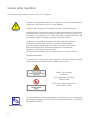
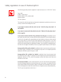
This manual contains important information about safe
installation and operation of the unit. Strictly comply with
this information to avoid harming people or damaging
property.
It is strictly prohibited to use this equipment with
radioactive chemicals!
Before switching this instrument on, read this manual
in its entirety. Keep the manual near the instrument for
future reference.
OPERATING INSTRUCTIONS FOR
"LOTUS EASY" SYSTEM
High Pressure warning: this device operates at MAX
8 bar pressure. Do not attempt to modify / increase
this parameter!
Read carefully!
ENGLISH edition
R2-11-14
1
This manual contains important information about SAFE installation and operation
of the unit. Read and retain for future reference.
Strictly comply with this information to avoid harming people or damaging property.
The information contained in this manual may contain inaccuracies or typographical errors.
The information contained in this manual is subject to change at any time without prior notice.
CE STANDARDS
Low Voltage Directive
⎬
2006/95/EC
EMC Electromagnetic Compatibility Directive
⎬
2004/108/EC
European harmonised standards under the Directive
⎬
2006/42/EC
• Pressure Equipment Directive (97/23/EC)
• EU Machinery Directive (2006/42/EC)
• EU EMC Directive (2004/108/EC)
• Low-voltage directive 2006/95/EC according to Appendix I, No. 1.5.1 of the Machinery Directive 2006/42/EC
• EU Pressure Equipment Directive (97/23/EC)
The following harmonized standards are considered:
• EN ISO 12100-1, EN ISO 12100-2, EN 809
• EN 60206, EN 60529, EN 610000-6-1/2/3/4
The following harmonized national standards are considered:
• DVGW standards: Technical rules W 224 and W 624
GENERAL NOTES ON SAFETY
During installation, testing and inspection it is mandatory to comply with the following
management and safety instructions.
2
Safety
This manual contains basic instructions for installation, operation and maintenance. It is therefore mandatory for the
installation technician and the equipment administrator to study the entire manual prior to installing and commissioning.
The manual must be found near the generator at all times. It is also mandatory for the operator to consider the general
rules listed in the "Safety standards" chapter as well as the specific safety instructions in the other chapters of this manual.
Warning
Some of the features described may not be available with the "LOTUS EASY" software release purchased. Or some functions
are available but not described in this manual. In this case, contact your dealer for more information.
Symbols
In accordance with the European guidelines concerning the characterisation of special risks, all safety instructions in this
manual are marked with the following symbols:
This symbol draws attention to the risks that may be encountered.
Failure to comply can lead to serious consequences for personal safety and damage to property.
Danger
This symbol draws attention to the problems that can be caused by incorrect equipment operation.
Attention
This symbol indicates additional important information.
Additional notes
3
PART ON THE DOSING PUMPS IN THE "LOTUS EASY" SYSTEM
The pump must only be used for dosing liquid products.
It should not be used in explosive atmospheres (EX).
It should not be used to dose flammable chemicals.
It should not be used with radioactive chemicals.
Attention
Use the pump only after installation.
Use the pump in accordance with the data and technical specifications on the label.
Do not modify or use differently from that indicated in the user manual.
Keep the pump protected from sun and rain. Avoid splashing water.
Additional notes
The power to the system must be immediately disconnected and the pump
disconnected from the electrical outlet during any emergency within the
environment where the pump is installed.
If you use particularly aggressive chemicals strictly comply with the regulations
concerning their use and storage.
Always comply with local safety regulations.
The manufacturer of the dosing pump cannot be held liable for damage to
persons or property caused by incorrect installation, improper or incorrect use
of the dosing pump!
Install the dosing pump so that it is accessible at all times for maintenance
purposes. Do not block the dosing pump area!
The unit must be controlled and powered by an external control system. Dosing
must be interrupted if there is no water. Power must be interrupted if there
is a malfunction.
Assistance and maintenance of the dosing pump and all its accessories must
always be performed by qualified personnel.
Before any installation and maintenance:
SYSTEM MUST BE INSTALLED IN A DEDICATED ROOM
• carefully read the chemical characteristics of the product to be dosed and
refer to the Safety Data Sheet of the product;
• wear the most suitable PROTECTIVE EQUIPMENT;
• drain the connection hoses of the dosing pump;
• carefully wash the hoses that have been used with particularly aggressive
materials.
4
General safety regulations
The manual describes the proper use of the "LOTUS EASY" generator.
Improper use of the generator compromises its safety function and that of the other devices
connected to it and therefore such use is strictly forbidden.
Installation and maintenance must only be carried out by authorised technicians.
Danger
Maintenance repairs should only be carried out only by the manufacturer or by technicians
authorised by the manufacturer. Interventions or alterations to the device that are not in
accordance with the provisions of this manual, with respect to regular maintenance, shall
be considered improper and render any product warranty null and void.
The operator is responsible for compliance with safety-related local regulations.
The device must be accessible at any time for operation and maintenance.
Before activating the dosing pumps, remove the pressure from the pump heads.
Before starting maintenance, drain and thoroughly wash the tested pumps.
Pay attention to the chemical safety data sheets!
Wear protective clothing when you must handle unknown or hazardous chemicals.
Placing of warning labels
In case there are no other special national regulations or directives, place the following
symbols and labels beside the entrance of the plant operation room:
Danger! Toxic substances
Prohibition!
No Fire, naked light and smoking
Chlorine dioxide
Access only for authorized personnel!
Sodium Chlorite - NaClO2
Additional notes
5
For proper compliance with European regulations concerning the use of this equipment
with hazardous chemicals, refer to EU directives DIN 939 (HYDROCHLORIC ACID) and DIN
938 (SODIUM CHLORITE)
Operating safety instructions
Strict compliance with all national and local regulations is required when using the "LOTUS
EASY" generator. The operator is responsible for compliance with safety-related local
instructions.
Danger
The generator must be installed and operated in accordance with the instructions in this
manual.
It is forbidden to use installation materials that are not approved by the manufacturer or
supplier.
The generator can only be used with appropriate safety valves approved by the manufacturer.
Failure to comply with this rule leads to be loss of the right to any kind of warranty!
Before operating the system, turn off the pressure from all parts of the system.
The system must never work with the valves closed as there lies the risk of the flexible
hoses or rigid hoses bursting.
Supplemental power supply breaker must be installed OUTSIDE the room where system is
installed. Disconnect the power supply before opening the controller container.
Additional notes
Pay attention to all the national regulations during installation.
The system must not be installed outdoors.
The system must be protected from unauthorised access.
The place where the unit is installed must be protected from direct sunlight and frost and
should be well ventilated.
Places with temperatures below 10°C must be provided with appropriate systems that
enhance the temperature.
It must be possible to transport the chemical containers to the system without any restriction.
An emergency exit is strictly required!
The system must be mounted on a vertical solid wall without stress.
The system must be mounted in such a way as not to cause vibrations.
Make sure free access from all sides is possible for operation and maintenance!
6
A valve and an attachable floor draining duct must be set up for any spilled chemicals to
be eliminated without any risk.
Safety regulations in case of chemical spills I
If the odour of chlorine dioxide (a penetrating odour similar to that of chlorine) can be smelt,
access is allowed only with the required personal protective equipment.
Danger
If the odour of chlorine dioxide is smelt, immediately turn off the system from a safe position,
for example with an emergency stop switch away from the system
In rare error cases, the hazardous ClO2 solution can leak. For example, install a gas detector
that disables the system in case of a leak of ClO2 and triggers an alarm that is recognised
at a distance.
When using hazardous substances, keep in mind that their latest safety data sheets provided
by the manufacturers are available. The safety data sheets indicate the measures to be
adopted. Since the risk potential of a substance can be evaluated at any time based on newly
learnt knowledge, the safety data sheet should be checked regularly and replaced if necessary.
The system administrator is responsible for the availability of the updated version of the
safety data sheet and the preparation of the risk assessment of the relative workstations.
The administrator generates hazardous substances with this system.
The administrator is obliged to adjust the operating instructions according to the system
if any recent knowledge concerning the risks of a particular hazardous substance is learnt
and must include how to avoid them or if national regulations contain different provisions
from those specified in the instruction manual supplied.
BYPASS LINE SAFETY INFORMATION
The reactor can explode:
Danger
• In case of an uncontrolled sucking of the chemicals into the reactor, caused
by a vacuum in the bypass-line and a simultaneous formation of gas/water
mixed phases, chlorine dioxide can gas out. Under adverse circumstances,
the critical gas concentration of 300 g/m3 is exceeded and an explosion of the
reactor can occur. Take appropriate measures to ensure that the bypass line of the
LOTUS EASY system does not become subject to a vacuum.
• Particles in the bypass water could block the flow meter. This can lead to an
unacceptably high concentration of chlorine dioxide. If a bypass line is not
completely full with water, a critical gas phase can form, resulting in an explosion
in the bypass line. Install a dirt-trap filter in the bypass line, if required.
Function: The bypass line is either fed from the main water supply or separately.
The purpose of the bypass line is to dilute the concentration of the chlorine dioxide
solution coming out of the reactor from approximately 20 g/l (= 20,000 ppm)
to approximately 0.1 - 1 g/l (= 100 - 1000 ppm) and to transport this solution to
the point of injection.
7
Safety regulations in case of chemical spills II
The following personal protective equipment is required to access the "LOTUS EASY" device
Attention
Face shield
Rubber or plastic boots
Protective gloves (ClO2 sealed model)
Protective apron
Full face respirator
The composition and the type of personal protective equipment required may vary from one
country to another and change over time.
If you come in contact with the acid: See the "Acid CE safety data sheet" of
the supplier.
Danger
If you come in contact with the chlorite: See the ''Chlorite CE safety data sheet''
of the supplier.
If you come in contact with the ClO2 solution or the ClO2 gas: immediately remove
the clothes that have come in contact with the chlorine dioxide or with the liquid solution,
wash the skin thoroughly with soap and plenty of water. Splashes in the eye must be washed
with running water for several minutes while keeping the eyelid wide open. If you have
inhaled chlorine dioxide move to a place where there is fresh air, lying down in a position of
absolute rest and protected from temperature changes. Consult a doctor immediately even if
the affects do not appear immediately. If necessary, organise rapid transport to the hospital.
Orange-yellow ClO2 gas has leaked: immediately clear the environment and disconnect
the power supply, for example, from the emergency stop switch. Use complete protective
equipment and water spray for the gas to settle.
Orange-yellow ClO2 solution has leaked: immediately clear the environment and
disconnect the power supply, for example, from the emergency stop switch. Wear protective
equipment and pour a ClO2 sodium thiosulphate solution then dilute with water and
eliminate into the drain.
An incorrect dilution or with concentrated HCl in the HCl tank and with dosing pumps
that have already pumped the concentrated chemicals to the reactor: immediately clear the
environment and disconnect the power supply, for example, from the emergency stop switch.
Alert the fire department and inform them of the risk of explosion due to concentrated ClO2.
The ClO2 gas can explode even after hours!
8
Storage, transport and repairs
In case of repairs, return the unit after having cleaned it and having washed the hydraulic
components. Attach the material decontamination declaration to be sent for repairs.
Additional notes
The unit can be damaged due to non-compliant storage or transport.
Store or transport the unit adequately packed, preferably in its original packaging.
Always follow the storage conditions when transporting or storing, even when the unit is
packed.
Although packed, always protect the unit from moisture and the action of chemicals.
Serious malfunctions at the plant or corrosion damages in the pipe-work of the treated water
should be possible in case the following requirements to the water – the chlorine dioxide
is produced for – as well as for the dilution water are not fulfilled:
Danger
Temperature: 10 – 30° C
Pressure: 5 bar max operating
Relative Humidity: 5% t ≤40 °C; 70% at 45 °C (non condensing).
Water quality: Free of iron, manganese and particles, non-corrosive.
The following directions are based on a concentration for chlorine dioxide of 0.4 mg/l to
prevent pipe-corrosion:
The pH-level should be always higher than pH 6.5. It should be controlled during operation.
In case the carbonate hardness is lower 1.1° dH or the alkalinity is lower 0.4 mMol/l the
dosing of suitable chemicals for the increase of the pH-level is required.
9
Introduction
The chlorine dioxide generator named "LOTUS EASY" is used to produce liquid chlorine dioxide. This disinfectant kills all
bacteria, germs, viruses and fungi very rapidly and works at very low concentration. The generator works according to the
hydrochloric acid - chlorite process and uses diluted chemicals such as hydrochloric acid (HCl 9%) and sodium chlorite
(NaClO2 7.5%) in accordance with the following chemical formula:
Hydrochloric acid + Sodium chlorite = Chlorine dioxide + Sodium chlorite + Water
4 HCl + 5 NaClO2 = 4 ClO2 + 5 NaCl + 2 H2O
In the process, each chemical is pumped with a certain proportion in a reactor, which works pressurised, by means of two
dosing pumps. The system can work proportionally with a contact water meter, a current signal or constant..
WARNING
follow European directive DIN EU 939 concerning HYDROCHLORIC ACID
follow European directive DIN EU 938 concerning SODIUM CHLORITE
follow Pressure Equipment Directive (97/23/EC)
Warnings for high pressure device
This machine may cause loss of life, severe bodily harm, or property damage if not correctly installed, operated and maintained. Read
and understand all guidelines given in this bulletin before attempting to open, operate or service this machine. Failure to
follow these guidelines and observe every precaution will result in malfunction and could result in catastrophic failure.
Misuse, incorrect assembly, or use of damaged or corroded components can result in high-velocity release of the end
closure. We recommend that only a qualified technician experienced in servicing high-pressure hydraulic systems, open,
close and service this machine.
The reactor can explode: If the chlorine dioxide solution in the reactor becomes subject to a vacuum, it
can explode. Hence the bypass line should be installed so that it is impossible for a vacuum to arise, not even when the
plant is stand-by or in the case of a fault.
Risk of explosion in the bypass line: If the dosing remains switched on when there is no water flow, it can lead to an
unacceptably high concentration of chlorine dioxide in the bypass line. If in addition, the bypass line is not completely full
with water, a critical gas phase can occur, resulting in an explosion in the bypass line.
10
Instrument main components
The "LOTUS EASY" instrument consists of the following main components.
1
2
3
2
4
3
5
6
7
8
9
10 11
12
13
14
15
1) "LOTUS EASY" control and management instrument
9) n/a
2) Hydrochloric acid dosing pump
10) Power Supply
3) Sodium chlorite dosing pump
11) Hydrochloric acid Level input
4) BYPASS Input
12) Flow sensor for H.Acid (SEFL)
5) mA Input (3- Black ; 2+ Red)
31
24
13) Standby or Gas detection Input
6) n/a
14) Sodium chlorite Level Input
7) Pulse sender Water Meter input
15) Flow sensor for S.Chlorite (SEFL)
8) Alarm output (3 ; 2)
11
31
24
System main components
The "LOTUS EASY"panel consists of the following main components. Panel size is 600 x 800 mm.
D
OUT
I
E
C
B
IN
F
A
G H
A) "LOTUS EASY" control and management instrument (5bar - 2l/h pumps: left pump for h.acid - right pump for s.chlorite)
B) Reactor chamber (max 8 bar)
C) Multifunction Valve Mod. MF
D) Static Mixer (product output to the plant)
E) Flow-meter “BYPASS” with flow switch
F) Water input
G) Hydrochloric acid input to the reactor chamber
H) Sodium chlorite input to the reactor chamber
I) Injection valve with spring made of Polytetrafluoroethylene (warning: injection point is under pressure)
12
Hydraulic connections
The hydraulic components to be installed for the pumps to properly work are:
Suction Hose with level probe and bottom filter
Delivery Hose with injection valve
Discharge hose
Suction Hose
Unscrew the suction ring nut completely on the pump body and draw the components required to assemble the hose:
tightening ring nut, Holding ring and hose holder.
Assemble as shown, making sure that the hose is fully inserted on the hose holder.
Tighten the hose on the pump body by tightening the ring nut with your hands.
Connect the other end of the hose to the bottom filter using the same procedure.
Suction Hose.
Tightening Nut
Holding ring
Hose holder
O-ring
Valve
Figure A
Delivery Hose
Unscrew the suction ring nut completely on the pump body and draw the components required to assemble the hose:
tightening ring nut, Holding ring and hose holder.
Assemble as shown, making sure that the hose is fully inserted on the hose holder.
Tighten the hose on the pump body by tightening the ring nut with your hands.
Connect the other end of the hose to the injection valve using the same procedure.
13
Discharge hose
Insert one end of the Discharge hose on the drain hose connection as shown in figure A (page 12).
Place the other end directly into the tank containing the product that is to be dosed. In this way, the liquid that leaked
during the priming phase will return into the tank.
Delivery hose
connection
Discharge handle
Discharge Hose
Suction Hose
connection
Self-venting pump body (chlorine dioxide dosing pump)
Discharge hose connection
Delivery hose
connection
Suction Hose connection
Note:
14
- the suction, delivery and discharge valves are DIFFERENT.
- the delivery and discharge hoses are of the same type.
- the Discharge hose can be slightly bent to be inserted into the tank of the product that is to be dosed.
Multifunction Valve Mod. MF
Multifunction valve is a 4 functions device. It works as a “Anti-syphon valve”,“Safety Valve” and “Bleed Valve”. Device
can be set to operate at selected pressures using knobs “S” and “A”.
Warning: Never turn knobs out of range!
Warning: Always connect discharge hose to multifunction valve!
Multifunction valve can modify the flow rate of the metering pump connected.
Verify the pump flow rate after installing the multifunction valve.
15
Multifunction Valve Mod. MF
Multifunction valve installation:
-Unscrew junction-nut (1) from multifunction valve.
-Remove the hose connection kit from pump’s delivery valve.
-Put junction-nut (1) on pump’s delivery valve. Be careful to the arrow direction on junction- nut(1) body.
-Place multifunction valve (turning discharge side as desired) on junction nut (1).
-Screw junction-nut(1) by turning it clock-wise until it’s completely locked.
Pressure valve operating mode:
“Pressure valve operating mode” keeps always closed the valve until is reached a specific pressure value to the input.
Pressure value may be set using the above procedure.
-Pull knob labeled “A” until it produces a “click”.
-Regulate pressure (bar) on desired value (within a range from 0 to 5bar).
-Press the knob labeled “A” until it produces a “click”.
Anti-syphon valve operating mode:
Anti-syphon operating mode avoid that dosing product goes through the injection valve when the pump is not dosing
because a negative pressure has been produced on the injection valve.
-Pull knob labeled “A” until it produces a “click”.
-Regulate pressure (bar) on 0bar.
-Press the knob labeled “A” until it produces a “click”.
Note: If product’s tank is installed above the injection valve adjust knob (A) calculating the height (0,1bar per meter
and adding 1bar).
Safety-valve operating mode:
Safety-valve operating mode activates product discharge through discharge hose when is over-reached a specific
pressure value (max 18bar). Manual discharge feature is also available.
Automatic product purge on over-reached pressure value:
-Pull knob labeled “S” until it produces a “click”.
-Regulate pressure (bar) on desired value (within a range from 0 to 18bar).
-Press the knob labeled “S” until it produces a “click”.
Manual product purge:
-Pull knob labeled “S” until it produces a “click”.
-Turn knob on “BLEED”.
-Regulate the pump flow knob on 0 (zero).
-Press the knob labeled “S” until it produces a “click”.
-Wait until purge ends then rotate knob back on previous position.
-Press knob until it produces a “click”.
16
Browsing the menus
At the top right of the "LOTUS EASY", there is a wheel used for menu browsing and programming the instrument. The
wheel can be rotated in both directions to move the cursor through the menus and pressed to confirm/enter selection.
NOTE: When changes have been made press the wheel on "OK" to save and exit from the sub-menu. Some menus show "ESC" followed by a saving menu.
Mode selection (see page 18 to choose instrument working mode)
Production (use this menu to set maximum gr/h production)
Water Meter (see working mode at page 18)
System Settings (see page 19 to manage inputs and password)
Instrument reset (revert instrument to default settings)
International (setup time / date / language)
Calibration Pump (see page 20 for setting pumps capacities)
Reactor Priming (see page 23 for testing pumps required time to fill reactor tank)
Exit (to main screen)
Access to main menu is restricted to ADMINISTRATOR ONLY
Default ADMIN password is 0916
Additional notes
Users with restricted access may access to PRODUCTION menu only
Default USER password is 0000
Main screen
Proportional mA mode
Costant Mode
Local Date & Time
Production g/h - % setpoint
mA input read value
Production g/h
Main Menu - Priming** - Stat***
Prming** see page 21
Stat***see page 24
Proportional mode
Local Date & Time
live ppm production - mc/h read by flow meter
overall dioxide production
Main Menu - Priming** - Stat***
17
Turn wheel for
browsing through
system status
Click wheel to enter
passcode and go to
main menu
Configuration and screens may differ; you may
download the latest version of this manual from
the manufacturer's website or by contacting
Technical Support. See page 22 for system
messages and warning explanation.
MODE SELECTION
Within main screen press the wheel and enter ADMINISTRATOR password. Select “Mode Selection”. Confirm changes by
moving cursor to “OK” and pressing the wheel.
Before to configure a working mode please verify chlorine dioxide (grams per hours) value set within “PRODUCTION” menu
Constant mode
This mode allows to produce chlorine dioxide based on % value. This
vallue is referred to “grams per hour” quantity set into “PRODUCTION”
menu. Below is shown [g/h] value according to set %.
Proportional WM
This mode allows to produce chlorine dioxide based on production [mg/l]
and water flow read by the external pulse sender water meter. To edit
water meter parameters move wheel on “OK” and press it.
Note: this menu can be set also within “WATER METER”menu
[mc]: total amount of cubic meters passed through water meter (totalizer)
FM input P/L: water meter counter mode (pulses per liter , liters per
pulse, 0/4-20mA)
RST TOT: totalizer reset
TIME OUT: countdown to alarm since the water meter no longer receive
pulses.
Proportional mA
This mode allows to produce chlorine dioxide proportionally to mA read
from “mA input” and % values set. For each mA field set the % value
according to value set into “PRODUCTION” menu. Note: a 0% value is
mandatory for at least one field.
E.g.: set 0mA at 15% and 20mA (automatically) will be set to 0%
According to value set into “PRODUCION” menu (8 g/h) the g/h fields
will refer to its % value:15% of 8g/h is 1.20g/h
18
SYSTEM SETTINGS
Within main screen press the wheel and enter ADMINISTRATOR password. Select “System Settings”. Confirm changes by
moving cursor to “OK” and pressing the wheel.
Use this menu to set contact working mode for each level input, bypass and standby (or gas detection) and admin / user
passwords.
L.HCL: contact type for chloridric acid level probe. Choose between N.C.
(normally closed) contact type or N.O. (normally open) contact type.
LNaCLO2: contact type for sodium chlorite level probe. Choose between
N.C. (normally closed) contact type or N.O. (normally open) contact type.
STDBY* / GAS DETECT*: contact type for STANDBY or GAS DETECTION
contact. Choose between N.C. (normally closed) contact type or N.O.
(normally open) contact type. STDBY contact can be also disabled.
*click on it to change input name
Bypass: contact type for flow detection. Choose between N.C. (normally
closed) contact type or N.O. (normally open) contact type.
Admin Passcode: 4 numbers code required to access all menus
User Passcode: 4 numbers code to access “production menu” only
Dos Check: required missing pulses from SEFL (flow sensor) before to
generate an alarm
19
CALIBRATION PUMP
Within main screen press the wheel and enter ADMINISTRATOR password. Select “Calibration Pump”. Confirm changes
by moving cursor to “OK” and pressing the wheel.
This function allows the calibration of the “Acid” and “Chlorite” dosing pumps based on strokes capability. To calibrate,
proceed as follows:
1. Choose which pump to calibrate by moving cursor on ACID or CHLORITE then press the wheel
2. Lay the tube of pump’s discharge within a graduated Beaker
3. Move cursor on Start, then press the wheel.
4. Wait until the end of the 100* strokes
5. Measure the product in the Beaker
6. Enter measured quantity in ml [ml field].
The instrument will calculate the cc/s that the pump is able to produce.
7. Move cursor on OK and press the wheel to save settings.
*this number can’t be edited. Please contact technical assistance for further information
20
PRIMING
Within main screen press the wheel and enter ADMINISTRATOR password. Select “PRMING”. Confirm changes by
moving cursor to “OK” and pressing the wheel.
This function allows to prime (load chemical into pump head) “Acid” and “Chlorite” dosing pumps.
1. Connect all hoses into proper places (delivery hose, suction hose and outgassing hose).
2. Open outgassing valve for required pump
3. Choose which pump to prime by moving cursor on ACID or CHLORITE then press the wheel
4. Move cursor on STK 000/000 and enter required strokes* for priming.
4. Move cursor on Start, then press the wheel.
5. All air inside the pump head will exit through the outgassing outlet. When product will leak from it, close immediately the outgassing valve.
6. End procedure by moving cursor on EXIT, press wheel to return to main screen.
*Usually 20 strokes are needed when suction hose is placed at 1.5mt height from tank bottom
21
STATUS MESSAGES
During working mode the instrument may show warning messages in main screen. See below table to better understand
and fix them.
Shown Message
EXPLANATION / What to do
STANDBY or GAS DETECTION*
Contact status has changed
LEVEL ACID or LEVEL CHLORITE*
Contact status has changed, this usually means low chemical
SEFL ACID or SEFL CHLORITE*
Flow sensor didn’t receive any signal from pump
(see “DOS CHECK” in SETTINGS menu)
BYPASS*
Contact status has changed
TIMEOUT*
Flow meter didn’t send any signal to LOTUS EASY
(see “WATER METER MENU” for settings)
OVERFLOW
Pumps are working at their maximum capacity, check production
(“PROPORTIONAL MODE” only)
VSUPPLY OUT OF RANGE*
Power supply exceeded working range - from 185 to 275 VAC
(check power supply)
*this alarm condition must be fixed in order to return to normal working mode!
22
REACTOR PRIMING
Within main screen press the wheel and enter ADMINISTRATOR password. Select “REACTOR PRMING”. Confirm
changes by moving cursor to “OK” and pressing the wheel.
This function allows to test “Acid” and “Chlorite” dosing pumps while filling main reactor. Set seconds required based
on pumps capacity and reactor tank size. Press start to begin procedure and STOP when reactor is full (liquid within
hose connected to injection valve). If not press STOP and increase seconds to fully accomplish reactor priming.
23
STATS
This menu shows statistics for both acid and chlorite pumps (liters or gallons dosed) and m/c or gallons passed through
the pulse sender water meter. To reset these values move cursor on “Reset: NO”, click, rotate wheel, choose YES, click
wheel, move on EXIT and confirm changes.
24
25
Technical Information
Power supply: 100÷240 VAC 50/60Hz
Power rating: 32W
Installation Class: I
Environment Relative Humidity 5% t ≤ 40°C; 70% at 50°C (non condensing)
Environment Temperature: 10 ÷ 30°C
Chemical Temperature: 0 ÷ 50°C
Reactor chamber max pressure: 8bar
Pollution Level: 2
Packaging and Transporting Temperature: -10 ÷ 50°C
Protection degree: IP65
Supplemental power supply breaker must be installed OUTSIDE
the room where system is installed.
26
Index
Safety page 3
Introductionpage 10
Instrument main components
page 11
System main components
page 12
Hydraulic connectionspage 13
Browsing the menus & main screen
page 17
Mode selectionpage 18
System settings page 19
Calibration pumppage 20
Primingpage 21
Status messagespage 22
Reactor Primingpage 23
Statistics page 24
Technical Informationpage 26
Indexpage 27
Information on this manual may contain technical inaccuracies or typographical errors.
The information contained may be changed at any time without prior notification or obligation.
27
All materials used in the construction of the instrument and for this manual can be recycled and therefore supporting the invaluable environmental resources of our planet. Do not dispose of harmful materials in the environment!
Check with the competent authority on the recycling programs for your area!
28