1
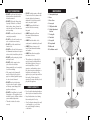
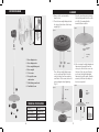
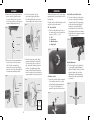
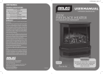
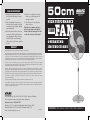
CPIN002693
CARE AND MAINTENANCE
1. Always disconnect the cord from
the electrical outlet when cleaning
your fan.
4. Avoid the use of gasoline, benzine,
thinner etc as they may result in
damage to the fan.
2. Light accumulated dust may be removed from the fan with a soft cloth
or vacuum cleaner using the dusting
brush attachment.
5. Store the fan in a clean dry place
when not in use.
3. Wipe the exterior surfaces of the fan
occasionally with a cloth moistened
(not dripping wet) with a mild soap
solution. Dry the case thoroughly
with a soft dry cloth before operating
the fan.
Warning: Do not immerse the fan in
water or allow water to drip into the
interior of the fan housing as this could
create a fire or electric shock hazard.
50cm
FAN
APF107
HIGH PERFORMANCE
130W
operating
instructions
WARRANTY
Arlec guarantees this product in accordance with the Australian Consumer Law.
Arlec also warrants to the original first purchaser of this product (“you”) from a retailer that this product will be free of defects in
materials and workmanship for a period of 12 months from the date of purchase; provided the product is not used other than
for the purpose, or in a manner not within the scope of the recommendations and limitations, specified by Arlec, is new and
not damaged at the time of purchase, has not been subjected to abuse, misuse, neglect or damage, has not been modified or
repaired without the approval of Arlec and has not been used for commercial purposes (“Warranty”).
If you wish to claim on the Warranty, you must, at your own expense, return the product, and provide proof of original
purchase and your name, address and telephone number, to Arlec at the address below or the retailer from whom you originally
purchased the product within 12 months from the date of purchase.
Arlec will (or authorise the retailer to) assess any claim you may make on the Warranty in the above manner and if, in Arlec’s
reasonable opinion, the Warranty applies, Arlec will at its own option and expense (or authorise the retailer to) replace the
product with the same or similar product or repair the product and return it to you or refund the price you paid for the product.
Arlec will bear its own expenses of doing those things, and you must bear any other expenses of claiming on the Warranty.
The Warranty is in addition to other rights and remedies you may have under a law in relation to the product
to which the Warranty relates.
Our goods come with guarantees that cannot be excluded under the Australian Consumer Law.
You are entitled to a replacement or refund for a major failure and for compensation for any other reasonably foreseeable loss
or damage. You are also entitled to have the goods repaired or replaced if the goods fail to be of acceptable quality and the
failure does not amount to a major failure.
Arlec Australia Pty. Ltd. ACN 009 322 105 (“Arlec”) gives the Warranty.
Arlec’s telephone number, address and email address are:
Customer Service: (03) 9982 5111
Building 3, 31 – 41 Joseph Street, Blackburn North, Victoria, 3130
Blackburn North LPO, P.O. Box 1065, Blackburn North, 3130
Email: [email protected]
CPIN002693
IMPORTANT! PLEASE READ THESE INSTRUCTIONS CAREFULLY.
CPIN002693
SAFETY INSTRUCTIONS
IDENTIFICATION
•
DO NOT tilt the unit. Always keep it upright. Position it on a flat and stable surface, where it cannot be easily knocked over. Take extra care when operating.
• ALWAYS ensure that the fan is
switched off before removing
the guard.
• ALWAYS unplug the unit from
the mains before maintenance
or cleaning.
• DO NOT connect the unit unless it completely assembled.
• DO NOT use the unit in a wet room, such as a bathroom or laundry
• DO NOT touch the unit with wet
hands or feet.
• DO NOT use the unit in the presence of inflammable substances or vapour such as alcohol, insecticides, petrol etc.
DO NOT pull the supply cord or place it near a heat source.
Always unwind the cord completely to avoid overheating.
•
If the supply cord is damaged it
must be replaced by the service agent or a similarly qualified person, in order to avoid a hazard.
•
DO NOT insert or allow foreign objects to enter the grille openings
as this may cause damage to the
appliance and/or user.
•
DO NOT allow children to play with this appliance. This appliance is not intended for use by children or infirm persons without supervision.
1. Outer pedestal pole
2. Base
10
3. Base Cover
4. Inner pole
5. Off/Speed switch
6. Height adjustment
fastener
8
7. Front grille
8. Fan blade
• ALWAYS use the switch on the
control panel to start and stop the unit.
9. Rear grille
• ALWAYS keep a clearance of at least 200mm from walls furniture and curtains
11.Motor unit
10.Carry handle
12.Oscillation control
9
• ALWAYS turn off and unplug the
unit when not in use.
• DO NOT use the mains plug to start and stop the unit.
•
DO NOT conduct repairs on this unit. It has been built in accordance with relevant safety and performance standards. An electrical specialist must carry out all repairs.
•
• DO NOT use this unit for functions other than those described in this instruction manual.
•
This appliance is not intended for
use by persons (including children)
with reduced physical, sensory or
mental capabilities, or lack of
experience and knowledge, unless
they have been given supervision or
instruction concerning use of the
appliance by a person responsible for
their safety. Children should be
supervised to ensure that they do not
play with the appliance
7
6
4
12
11
ENERGY SAVING TIPS
1
• Do not locate the fan where furniture or
other objects can obstruct the air flow.
3
• Keep blinds/curtains closed during the sunniest part of the day
• This unit is intended for indoor
use only.
•
2
Close the fireplace damper, floor and/
or wall registers, so cool air does
not escape through the chimney
or duct work.
3
2
5
CPIN002693
EXPLODED DIAGRAM
ASSEMBLY
1. Remove all the sub assemblies
from the box.
Place the base fixing device through
the base fixing washer into the outer
pole (Fig.3), ensuring that the
assembled base is stable.
2. Place the base weight fixing nuts into
the holes at the bottom of the heavy
weight (Fig.1).
8
Figure 3
Figure 1
7
6
Base Fixing
Washer
Base Weight
Base Fixing
Device
1. Base fixing device
2. Base fixing washer
3. After loosening the height adjustment
fastener and removing it from the
outer pole, slide the base cover onto
the base of the outer pole. Replace
and secure the height adjustment
fastener into position again. Now the
assembly of the fan base with pole
has been completed.
Base Nuts
3. Base weight fixing nuts
4. Base weight
5. Pole screws
6. Rear grille screws
and washers
7. Grille fixing screw & nut
8. Fan Blade Screw
Place the base weight fixing screws
one by one through the holes in the
outer pole flange and base, making
sure that all of the screws, holes and
nuts are aligned before tightening.
(Fig .2).
Figure 4
Figure 2
5
Pole Screws
Height
Adjustment
Fastener
Base
TECHNICAL SPECIFICATIONS
4
3
2
1
4
Model No
APF107
Rated Voltage
220-240V a.c.
Rated Frequency
50Hz
Power
130W
Base Cover
Base Weight
Pole
5
CPIN002693
ASSEMBLY
OPERATION
4. Remove the 2 pole screws from the
motor connector, place the motor
connector into the inner pole and
secure into position by replacing pole
screws and tightening securely.
6. Place the fan blade onto the
motor shaft, aligning the flat on
the shaft with the fan blade screw.
Securely tighten the fan blade screw.
Figure 7
Make sure that you read all of the safety
warnings before you operate this unit for
the first time.
Vertical Direction of Motor Unit
3. The vertical direction of the motor
unit can be adjusted by tilting the
complete head unit (incorporating
motor unit and assembled grille)
forward or back ward until the
desired direction is reached. Note
that stepped positions are obtained
within the neck locating mechanism
of the motor connector.
Plug the unit to a standard mains socket
and turn on the mains switch.
Off / Speed Switch
Figure 5
Fan Blade
Screw
Motor Connector
Inner Collar
Fan Blade
Pole Screws
7. After loosening, remove the fixing
screw and nut from the front grille.
Place the front grille over the rear
grill, press grille retaining clips into
position, then tighten grille fixing
screw and nut. Ensure that the fan
blade is completely enclosed and the
complete grille is securely in position.
5. Remove the 4 screws and washers
located on the front of the motor
unit. Place the rear grille into
position on the motor unit (handle
up), then secure in position with the
4 screws and washers provided.
Figure 6
Figure 7
Grill Screws
& Washers
Front Grille
Grille Retaining
Clips (6)
1. Turn the rotary switch on the top of
the motor unit to select between fan
speeds: 0 (OFF),1, 2 or 3.
0= Off
1= Low Speed
2= Medium Speed
3= High Speed
Figure 10
Figure 8
Height Adjustment
4. The fan height can be adjusted by
loosening the height adjustment
fastener, lifting the inner pole (with
attached motor unit), and then
tightening the height adjustment
fastener when the desired height
is obtained.
Oscillation Control
2. Push the oscillation knob downward
to allow the motor unit to oscillate
horizontally through approximately
90° angle. Lift oscillation knob
upward to turn off oscillation mode.
Figure 10
Figure 9
Tighten
OFF
Rear Grille
Grille Fixing
Screw & Nut
ON
6
7
Loosen