1
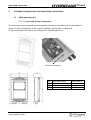
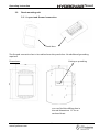
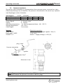
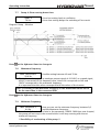
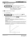
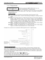
Operating Instructions
210981-2
Smart 4-ENN
Smart
Operating Instruction
Index
1 Important safety instructions ........................................................................ 5
2 Technical Data................................................................................................ 7
3 Included components and mounting instructions ......................................... 8
3.1 Wall mounting unit ................................................................................ 8
3.1.1 Layout and Ground connection ............................................................................... 8
3.2 Panel mounting unit .............................................................................. 9
3.2.1 Layout and Ground connection ............................................................................... 9
3.2.2 Included Component ............................................................................................. 10
3.3 Explosion drawing................................................................................ 10
3.4 Pressure transducer.............................................................................. 11
4 Control Terminals and Display unit ............................................................. 12
Terminals of the HYDROVAR-Smart ............................................................ 13
4.2 Display unit .......................................................................................... 14
5 Language Selection...................................................................................... 14
6 Parameters of the main menu ..................................................................... 15
7 Settings in the Secondary Menu .................................................................. 19
7.1 JOG-MODE............................................................................................ 19
7.2 Window - %.......................................................................................... 19
7.3 Ramp Hysteresis ................................................................................... 20
7.4 Ramp 1: Fast running up time:............................................................. 20
7.5 Ramp 2: Fast running down time:........................................................ 20
7.6 Ramp 3: Slow running up time: ........................................................... 20
7.7 Ramp 4: Slow running down time: ...................................................... 21
7.8 Maximum Frequency............................................................................ 21
7.9 Minimum Frequency ............................................................................ 21
7.10 Operation at the minimum frequency ............................................... 22
7.11 Delay time for shut off at minimum frequency ................................. 22
7.12 Sensor – Adjust................................................................................... 22
7.13 Sensor - Curve .................................................................................... 22
7.14 Setting of the sensor range................................................................ 23
7.15 Operation Mode ................................................................................. 23
7.16 Control Response ............................................................................... 24
7.17 Start Value.......................................................................................... 24
7.18 2nd Required Value.............................................................................. 25
www.hydrovar.com
2
Operating Instruction
Smart
st
7.19 Configuration of 1 relay ................................................................... 26
7.20 Submenu Offset ................................................................................. 26
7.20.1 Source of the Offset input ................................................................................... 26
7.20.2 1st Offset level...................................................................................................... 27
7.20.3 2nd Offset level ..................................................................................................... 27
7.20.4 INTENSITY 1 ......................................................................................................... 27
7.20.5 INTENSITY 2 ......................................................................................................... 27
7.20.6 Example for the Offset:........................................................................................ 28
7.21 Submenu Sequence control ............................................................... 29
7.21.1 Lift Value ............................................................................................................. 29
7.21.2 Fall Value ............................................................................................................. 30
7.21.3 Release frequency of the following controller...................................................... 30
7.21.4 Switch Interval ..................................................................................................... 31
7.21.5 Source of required value ...................................................................................... 31
7.21.6 Synchronous Control ........................................................................................... 31
7.21.7 Pump status indication ........................................................................................ 32
7.21.8 Error Signals for Data Bus Interruptions............................................................... 33
7.22 Submenu - RS 485 Interface ............................................................... 33
7.22.1 Pump Address...................................................................................................... 33
7.22.2 ADC Reference ..................................................................................................... 33
7.23 Compensation Frequency................................................................... 34
7.24 Lift-Intensity ....................................................................................... 34
7.25 Analogue output 1 ............................................................................. 35
7.26 Unit..................................................................................................... 35
7.27 Automatic test run ............................................................................. 35
7.28 Submenu for manual test run ............................................................ 36
7.28.1 Activate manual test run...................................................................................... 36
7.28.2 Test Frequency..................................................................................................... 36
7.29 Submenu - Error ................................................................................. 36
7.29.1 Conveyor Limit..................................................................................................... 36
7.29.2 Delay Time ........................................................................................................... 37
7.29.3 Automatic Error reset........................................................................................... 37
7.29.4 Erase Error memory ............................................................................................. 37
7.30 Operating Hours................................................................................. 37
7.31 Display - Contrast ............................................................................... 38
7.32 Set Password ...................................................................................... 38
7.33 Operating Lock ................................................................................... 38
7.34 Setting Default Values........................................................................ 38
7.34.1 Default Values Europe ......................................................................................... 38
7.34.2 Default Values USA .............................................................................................. 38
7.35 Saving................................................................................................. 39
8 Error Signals................................................................................................. 40
8.1 Low Water ............................................................................................ 40
8.2 Conveyor Control ................................................................................. 40
8.3 Overheating – Motor ............................................................................ 40
www.hydrovar.com
3
Operating Instruction
Smart
8.4 Pressure Sensor Error ........................................................................... 40
8.5 Pressure Sensor Error I < 4 mA .......................................................... 40
8.6 Additional Error signals:....................................................................... 41
9 RS 485 - Interface......................................................................................... 41
10 Auxiliary Texts............................................................................................. 42
11 Maintenance ............................................................................................... 42
12 Diagram of all Software parameters........................................................... 43
Follow the Pump Operating and Maintenance Instructions
We reserve the right to alter specifications
www.hydrovar.com
4
Smart
Operating Instruction
1
Important safety instructions
Read and follow the operating instructions
and safety instructions carefully before
starting operations! All modifications must be
done by qualified technicians!
In addition to the instructions contained in these operating instructions please pay
attention to universal safety and accident prevention regulations.
The HYDROVAR-Smart drive head must be disconnected from the power supply before any
work can be carried out in the electrical or mechanical part of the system.
Installation, maintenance and repair work may only be carried out by trained, skilled and
qualified personnel.
Unauthorised modifications or changes to the system make all guarantees null and void.
When in operation, the motor can be stopped by remote control, whereby the inverter and
the motor remain under voltage. For safety reasons, the unit has to be disconnected from the
power supply when carrying out work on the machinery as locking out the equipment by
switching off the release mechanism or set value cannot prevent accidental starting of the
motor.
The HYDROVAR-Smart works with a low voltage supply of 24VAC/DC.
Nevertheless it is not allowed to touch any parts of the unit, when power
supply is on. Because of the possibility to connect external voltages to the
relays, at some places of the HYDROVAR-Smart, there can be dangerous
voltages!
Touching these components seriously endangers life !
Before removing the HYDROVAR-SMART the system must be disconnected
from the power supply. After switching off the power supply wait
at least 5 minutes before starting work on or in the HYDROVAR-SMART
drive head (the capacitors in the intermediate circuit of the inverter have to
be discharged by the installed discharge resistors first).
Please refer also to the instruction manual of the connected frequency
converter and read it carefully!
Furthermore, care must be taken not to short circuit the neighbouring
components when connecting the external control wires and that open
cable ends which are not in use are isolated.
www.hydrovar.com
5
Smart
Operating Instruction
The HYDROVAR-SMART control unit contains electronic safety devices
which switch off the frequency drive in the event of faults, whereby the
motor has zero current but remains energised and comes to a halt. The
motor can also be halted by mechanical blocking. If it is switched off
electronically the motor is disconnected from the mains voltage
through the electronics of the frequency converter but is not potentialfree in the circuit.
In addition voltage fluctuations, especially power failures can cause the
system to switch off itself.
Repair of faults can cause the motor to start up again!
The system is only allowed to be put into operation when it has been earthened. In
addition, efficient grounding of all pipes must be ensured.
The operating instructions must be read, understood and followed by the operating
personnel. We point out that we accept no liability for damage and operating disorders
which are the result of non-compliance with the operating instructions.
Warns that disregarding of the regulations may cause electric shock.
Warns that disregarding of the regulations may cause personal injury or
damage to property.
www.hydrovar.com
6
Smart
Operating Instruction
2
Technical Data
HYDROVAR Smart
Type
Wall mounting unit
Panel mounting unit
Supply Voltage
Voltage
Max. Current
24 VAC/DC
130 mA
24 VAC/DC
130 mA
Output Signal
to the Inverter
0 – 10 VDC
0 – 10 VDC
Weight
kg
1,70
0,5
The HYDROVAR-Smart is tested according to the following standards:
EN 50081-1
EN 50082-1
EN 61010-1
Ambient temperature:
Storage temperature:
Humidity:
Air pollution:
Class of protection :
www.hydrovar.com
+5° C ... +40°C
-25° C ... +55° C (+70°C during max. 24 hours.)
RH max. 50% at 40°C, Unlimited
RH max. 90% at 20°C, max. 30 days per year
75% average per year (Class F, DIN 40 040)
Condensation is not permitted !
The air may contain dry dust as found in workshops where
there is no excessive quantity of dust due to machines.
Excessive amounts of dust, acids, corrosive gases, salts etc.
are not permitted
Wall mounting unit ..... IP 55
Panel mounting unit ... IP 00
7
Smart
Operating Instruction
3
Included components and mounting instructions
3.1
Wall mounting unit
3.1.1 Layout and Ground connection
The back cover can be opened by removing the 4 screws on the back side of the HydrovarSmart. For the arrangement of the control terminals, please refer to chapter 4.
The grounding has to be done according to the following pictures.
Ground connection
pcs.
2
2
2
www.hydrovar.com
8
Cable gland type
M16x1,5
M12x1,5
Rubber plug for M12
Max.Cable Ø
10mm
7,5mm
7,5mm
Smart
Operating Instruction
3.2
Panel mounting unit
3.2.1 Layout and Ground connection
Panel door
The Ground connection has to be realised over the panel door. No additional grounding
required!
Dimensions:
Cutting or punching
You can find the drilling plan in
the real dimensions 1:1 on an
enclosed sheet.
www.hydrovar.com
9
Smart
Operating Instruction
3.2.2 Included Component
à
à
à
à
à
à
à
à
à
à
à
à
à
1 x HYDROVAR-Smart print
1 x Display unit
1 x Display-sealing
1 x Front cover
1 x Plastic cover
1 x Label (SCH 60.25)
1 x Label (SCH 60.35)
4 x Distance bolt M4xM4x22 I/I
4 x Distance bolt M4xM4x8 A/I
4 x Screw M3x10
4 x Screw M4x10
4 x Screw M4x6
8 x Washer M4
3.3
Explosion drawing
Plastic cover
HYDROVAR-Smart
print
Display-sealing
Front cover
Display unit
M4x10
Washer M4
Distance boltM4xM4x22 I/I
M3x10
Distance bolt M4xM4x8 A/I
Washer M4
M4x6
The self-adhesive label SCH 60.25 (with the cut-out for the display) has to be fixed in this way,
that the yellow areas are placed on top of the push buttons.
The self-adhesive label SCH 60.35 has to be fixed under the display unit.
A photo of the right place for these labels is shown on the first page of this instruction
manual!
www.hydrovar.com
10
Smart
Operating Instruction
3.4
Pressure transducer
The sensor of this transmitter is a piezoresistive silicon pressure sensor, mounted on a tape
(TAP) freely floating in an oil chamber. The pressure is transferred to the sensor by a separate
steel diaphragm in the oil chamber.
Specification
PA-22S (4-20mA)
Range (FS):
10 bar
16 bar 25 bar 40 bar
Max. pressure – Pmax:
20 bar
30 bar 50 bar 80 bar
Class of protection
IP 67
Output signal:
4...20 mA; 2-wire
Supply:
8 – 28 VDC
Operating temperature: -10...80°C kompensated (max. –40...135 °C)
Storage temperature:
-40...135°C
Cable length:
2 m (screen)
Material:
Body: 1.4435
Diaphragm: 1.4435
Thread: G ¼“
Electrical connection:
White = Analogue output signal(+ Out) (1)
2 not used
Brown = Supply voltage (+ VCC) (3)
plug / cable
Pressure transmitter
gasket
gasket Viton®
Measures in mm
Note: To guarantee the protection class IP67, the rubber gasket has to be
mounted between the pressure transducer and the plug!
www.hydrovar.com
11
Smart
Operating Instruction
4
Control Terminals and Display unit
All externally used cables have to be shielded. Do not connect the ground of the electronic
components to other potentials (all electronic ground and GND of the RS 485-interface are
connected together internally).
For external on/off switches, (terminals X1/4 – X1/5) contacts, which are suitable for switching
low voltages <10 VDC, are necessary.
If unshielded control cables are used, signal interference may occur and interfere with
the function of the controller.
Terminals:
X1/
1
2
3
4
5
6
7
8
9
10
11
12
13
14
Terminal:
(for dry
Contacts)
GND
Actual value input 4...20mA, 50 Ohm internal load resistance
Power supply for external transducer; 15VDC, max. 100mA
GND
5 VDC for external on/off (release); Ri=10kOhm,
(gold plated contact necessary!)
GND
5 VDC for external low water protection; Ri=10kOhm,
(e.g. incoming pressure switch or water level switch)
Thermal switch or PTC (in motor terminal box)
Thermal switch or PTC
GND
Analogue output 2; 0...10 VDC (see chapter 7.25)
Current signal input 4...20mA
Voltage signal input 0...10V or 2...10V
Digital input for activating of 2nd required value
X2/ 1
2
3
4
Fault signal relay
Fault signal relay
Fault signal relay
Pump operation
signal relay
5 Pump operation
signal relay
6 Pump operation
signal relay
NC
CC
NO
NC
max. 250VAC
max. 250VAC
max. 250VAC
max. 250VAC
1A free of inductivity
1A free of inductivity
1A free of inductivity
1A free of inductivity
CC
max. 250VAC
1A free of inductivity
NO
max. 250VAC
1A free of inductivity
!! Fault relay (X2/2 - X2/3) is closed, when there is no error!!
Terminal:
X3
Display
Terminal:
X5-6/ 1
2
3
4
RS 485
RS 485
RS 485
RS 485
www.hydrovar.com
SIO LOW
SIO +
HIGH
GND
+ 5 VDC max. 20mA out
For supply of external interface
converter
12
Smart
Operating Instruction
Terminal:
X8
RS 485
Terminal:
X9/1
2
3
4
5
6
24 VAC or DC+
Supply Voltage
24 VAC or GND
Supply Voltage
Error relay of the connected VFD
Error relay of the connected VFD
Analogue output for the speed signal of the VFD (0-10V DC)
GND
4.1
Terminals of the HYDROVAR-Smart
Display
Screen
1
Actual value signal input 4-20mA
2
External on/off
External low Water
X3
3
5
2
24V AC/DC+
6
1
24V AC/DC-
Ground
10
Analogue output 2; 0-10V
11
Current signal input 4..20mA 12
Voltage signal input 0..10V or 2..10V 13
Digital input 14
RS 485
Analogue output 1 (0-10V)
to the VFD
4
9
Pump running signal
5
3
8
Fault signal
GND
4
7
Motor thermal switch or PTC
6
NC
1
CC
2
NO
3
NC
4
CC
5
NO
6
SIO -
1
Error Relay of the VFD
Supply Voltage
HV - Smart Controlcard
+15 VDC max. 100mA
X9
X1
X2
X5
SIO + 2
GND
3
+ 5V 4
X8
3
GND
RS 485
+ 5V 4
SIO + 2
SIO -
1
X6
RS 485
When connecting more variable speed drives (max. 4 pumps) via the interface RS 485, the
terminals X5/1/2/3 or X6/1/2/3 of each Hydrovar-Smart have to be connected together by
using a shielded cable and have to be programmed accordingly (see chapter 7.21).
www.hydrovar.com
13
Smart
Operating Instruction
4.2
Display unit
ON
OFF
Select
Power supply OK
5
Run indication
Fault indication
Language Selection
The information on the display can be called up in German, English, Italian,
French, Spanish, Portuguese or Dutch.
To select the required language proceed as follows:
Briefly press
and
simultaneously (in 1st display);
Þ the actual language will now appear in the second line and the desired
language can be selected with the buttons
or . After the language has been
st
briefly and the 1 display of the main menu will appear again.
selected, press
If only the language is changed it is not necessary to SAVE.
www.hydrovar.com
14
Smart
Operating Instruction
6
Parameters of the main menu
After connection of the Hydrovar-Smart unit to the power supply the following displays
become visible.
SW-Ver:
Date:
HV00-001
xxxx
The current software version with the date
of programming is displayed for about 3s.
The following two displays are depending on the selected mode:
a) Active MODE = Controller:
1.
ITT INDUSTRIES
XX.X BAR
Continue by pressing the
2.
This window is mentioned several times in the
Operating Instructions as 1st display at Mode Controller
-button
Set the desired set pressure with either
or
and
then briefly press the -button.
If several pumps are connected via the RS-485 interface, one pump must be ready
for operation when the set pressure is changed, otherwise the set value will not be
accepted by the follow-up pumps. Afterwards the new required pressure has to be
saved in all pumps.
REQUIRED VALUE 1
X.XX BAR
If you want to change to Required Value 2 you have to close the external
contact, connected to X1/10-X1/14.
After closing this contact, the display changes from Required value 1 to
2.1
REQUIRED VALUE 2
In this window, there is shown the condition of
ADC-X XX.X BAR
the second Required value.
ADC-X: This parameter shows the source of the external or internal value (see
chapter 7.18).
XX.X Bar: shows the actual value of the Required Value 2.
Continue by pressing the
www.hydrovar.com
-button (to point 3)
15
Smart
Operating Instruction
b) Active MODE = Actuator:
1.
ITT INDUSTRIES
Frequency XX.X Hz
Continue by pressing the
2.
-button
REQUIRED VALUE 1
X.XX BAR
Continue by pressing the
This window is mentioned several times in the
Operating Instructions as 1st display at the Mode
Actuator.
Not active in the actuator mode, because the
internal controller is not active.
-button (to point 3)
c) Active MODE = Synch. Controller or Multicontroller:
1.
ADR (X) P X
XX.X Bar
Continue by pressing the
2.
This window is mentioned several times in the
Operating Instructions as 1st display in the
Synch. Controller or Multicontroller mode.
-button
REQUIRED VALUE 1
X.XX BAR
Set the desired set pressure with either
or
and
then briefly press the -button.
If several pumps are connected via the RS-485 interface, one pump must be ready
for operation when the set pressure is changed, otherwise the set value will not be
accepted by the follow-up pumps. Afterwards the new required pressure has to be
saved in all pumps.
If you want to change to Required Value 2 you have to close the external
contact, connected to X1/10-X1/14.
After closing this contact, the display changes from Required value 1 to
2.1
In this window, there is shown the condition of
the second Required value.
ADC-X: This parameter shows the source of the external or internal value (see
chapter 7.18).
XX.X Bar: shows the actual value of the Required Value 2.
REQUIRED VALUE 2
ADC-X XX.X BAR
Continue by pressing the
-button (to point 3)
d) Active MODE = Actuator local:
1.
ITT INDUSTRIES
Frequency XX.X Hz
Continue by pressing the
www.hydrovar.com
This window is mentioned several times in the
Operating Instructions as 1st display at the Mode
Actuator local.
-button
16
Smart
Operating Instruction
2.
Set the desired output frequency with either
or
and then briefly press the -button.
If several pumps are connected via the RS-485 interface, you have to set this
parameter on each pump!
ACTUATOR LOCAL
X.X Hz X.XX BAR
Press the
button on the Hydrovar-Smart to change to
!! The following displays of the main menu are valid for all selected Modes !!
AUTO - START
ON
3.
Select (ON) with the
button or (OFF) with
.
AUTO-START ON starts the pump automatically after a failure of the power supply.
If AUTO-START is OFF, the Hydrovar-Smart has to be restarted by pressing the
buttons (OFF) and then
(ON) after a power supply failure.
If the AUTO-START is OFF, the unit will not start again in cases of a power supply
failure or disconnection. After restarting the following message is shown:
NO AUTOSTART
disable inverter
3.1
To restart the unit, press at first the
Press
and then the
button for the start.
and the display changes to
All errors are only readable in English language
Note:
4.
ERROR 1
.........................
Press the
button to change to
5.
ERROR 2
Here, there is shown the last error
Shows the error before the last error
.........................
Press the
6.
button to change to
ERROR 3
Shows the error before error 2
.........................
Press the
button to change to
7.
ERROR 4
Press the
.........................
Shows the error before error 3
button to change to
www.hydrovar.com
17
Smart
Operating Instruction
8.
ERROR 5
Shows the error before error 4
.........................
Press the
button to change to
9.
TOTAL RUN TIME
0000:00
Press the
button to change to
Runtime of the motor.
This time can be reset together with the
Operating hours (see chapter 7.30).
Note: All changes have to be saved, that they will not be lost in case of shut off
of the power supply !!
10.
SAVE ???
Simultaneously press buttons
11.
SAVE ???
SAVED
appears on the display. After five seconds the
display jumps back to the 1st display.
+
and
until...:
These parameters can also be set during operation; To do so, briefly press the button
and repeat steps 1 – 10.
Note: Often shown displays:
12.
INVERTER LOCKED
enable inverter
This message appears when the connection of
terminal X1/4-X1/5 is open (external release contact).
To start the Hydrovar-Smart, connect these terminals by closing the external release contact or
by using a short-circuit connection!
www.hydrovar.com
18
Smart
Operating Instruction
7
Settings in the Secondary Menu
Important! Before entering the secondary menu, these instructions
have to be read carefully to prevent incorrect settings which could cause
malfunction.
Secondary Menu:
Stop motor by pressing
Press
INVERTER STOP
ON -> START
(OFF)
PASSWORD
0000
for 3 seconds to change to
PASSWORD
0066
Set ‘Password 0066’ by pressing
Note: The password must be entered at each entry!
J O G – MODE
0.0Hz X.XX Bar
Confirm by pressing
and the first
window of the sub menu is shown
In the following paragraphs all possible settings are listed (in the display, there is
shown the European default setting).
7.1
JOG-MODE
Display and Manual Operation Mode
J O G – MODE
Actual outgoing frequency and actual analogue input
0.0Hz X.XX Bar
are shown. By pressing
or in this menu, the
internal controller of the Hydrovar-Smart will be shut off and the inverter changes
to manual mode. With the buttons and
you can set any constant speed.
Setting of 0,0 Hz stops the inverter. If the JOG-MODE is left at a frequency higher
than 0,0 Hz the inverter will continue its normal automatic operation.
Press
on the Hydrovar-Smart to change to
7.2
Window - %
WINDOW
This value indicates the max. variation of the outgoing
5%
pressure (see diagram “Ramp window” in chapter 7.7).
Possible setting: between 0% - 100% of required value.
Press
on the Hydrovar-Smart to change to
www.hydrovar.com
19
Smart
Operating Instruction
7.3
Ramp Hysteresis
Level, where the fast ramps are changing to the slow
RAMP HYSTERESIS
80%
ramps (see diagram “Ramp window” in chapter 7.7)
Possible setting: between 0%..100% of the window
Press
on the Hydrovar-Smart to change to
7.4
Ramp 1: Fast running up time:
Time setting at Ramp 1, 2, 3, or 4 will influence the control of the pump and
MUST NOT BE CHANGED at normal operation. Possible setting of each ramp
0,05 - 1000 sec.
Please take care, that the ramp times of the connected VFD are every time faster
than the settings of the ramps 1-4 of the HYDROVAR-Smart!
The fast ramp times 1 and 2 are determined by the power of the connected drive.
(Standard settings = 4-15s, depending on the power)
RAMP 1
4.0 Sec
Press
on the Hydrovar-Smart to change to
7.5
Ramp 2: Fast running down time:
RAMP 2
4.0 Sec
Press
Excessively fast running up time may overload the
inverter in the starting moment.
Excessively slow running up time may cause a break
down of the outgoing pressure during operation.
Excessively fast running down time tends to cause
oscillation or hunting or can cause an error
(OVERVOLTAGE) during ramp down of the pump.
Excessively slow running down time tends to generate
over pressure.
on the Hydrovar-Smart to change to
7.6 Ramp 3: Slow running up time:
The following ramps 3 and 4 determine the speed of the internal Hydrovar-Smart
controller and depend on the system, which should be controlled.
RAMP 3
70 Sec
Press
A too slow running up time can cause a break of the
outgoing pressure during variation of the demand.
A too fast running up time may lead to oscillation and/or
overload of the inverter.
on the Hydrovar-Smart to change to
www.hydrovar.com
20
Smart
Operating Instruction
7.7
Ramp 4: Slow running down time:
RAMP 4
70 Sec
A too fast setting leads to oscillation
A too slow setting delays the switching off too much
Diagram: Ramp – Window
Press
on the Hydrovar-Smart to change to
7.8
Maximum Frequency
MAX. FREQUENCY
Possible setting between 40 and 70 Hz.
50.0 Hz
The Hydrovar-Smart gives an analogue output signal of 0-10VDC as a speed signal,
which is connected to the frequency drive, where 0V corresponds to 0Hz and
10VDC corresponds to the maximum frequency.
It is important that this values correspond with the values of the inverter.
Note: The setting of the Maximum frequency in the HYDROVAR-Smart has to
be the same than in the connected VFD!
Press
on the Hydrovar-Smart to change to
7.9
Minimum Frequency
MIN. FREQUENCY
Here you can set the minimum frequency between 0,0
0.0 Hz
and the Maximum frequency.
Attention!: If there is set f>fmin in the parameter CONFIG. FMIN (see next chapter)
the pump will not stop in the normal mode. It will keep running with the set
minimum frequency.
!! Possibility of overheating of the pump !!
www.hydrovar.com
21
Smart
Operating Instruction
Press
on the Hydrovar-Smart to change to
7.10 Operation at the minimum frequency
CONFIG FMIN
If you have selected „f->0“ the frequency will go
f => fmin
down to the selected minimum frequency.
Then the inverter will keep running for the selected stop-delay time and after this
time the Hydrovar-Smart will stop automatically.
If the selection is „f->fmin“ you can not run the pump below the set minimum
frequency. In the controller, actuator and multi controller mode the pump will
never run below the set minimum frequency (the pump will only stop with an
external on/off-(terminals X1/4 and X1/5) or in case of a failure.
Press
on the Hydrovar-Smart to change to
7.11 Delay time for shut off at minimum frequency
STOP-DELAY FMIN
After running the pump for this selected time at
5s
minimum frequency, the pump will stop, if parameter
CONFIG. FMIN (see chapter 11.10) is set to f Þ 0
Adjustable between 0 and 100s.
Press
on the Hydrovar-Smart to change to
7.12 Sensor – Adjust
SENSOR_ADJUST?
Zero point adjustment of the transmitter
Out of range
Depressurise the system and press buttons
+
simultaneously. After a successive adjustment, "adjusted" appears on the display.
If “out of range” is shown on the display, no adjustment is possible
Press
on the Hydrovar-Smart to change to
7.13 Sensor - Curve
SENSOR-CURVE
Function of the input signal (4...20mA) of the
Linear
Hydrovar to the actual measured value.
Application:
linear: Pressure control, differential pressure control, level, temperature and flow
control (inductive or mechanical).
quadratic: Flow control by using an orifice plate together with a differential
pressure transmitter.
www.hydrovar.com
22
Smart
Operating Instruction
Press
on the Hydrovar-Smart to change to
7.14 Setting of the sensor range
SENSOR RANGE
20mA = 10.0Bar
Setting of the maximum value of the measuring
transmitter, which corresponds to
20mAe.g. 10.0 bar = 20mA of the pressure transmitter
Adjustable ranges: Bar: 0.2...100 bar; psi 2.9...1450psi;
m3/h: 4...2400m3/h; g/min: 9...10560g/min
mH2O: max 1019,5mH2O; ft: max 3345ft
0...100 %; or without unit: max 1000;
Press
on the Hydrovar-Smart to change to
7.15 Operation Mode
MODE:
Select your required Mode by using the
and
Controller
buttons
If only one HYDROVAR-Smart pump is in operation set the Controller. If more than
one pump work together via the RS485 interface (follow-up pump control), the
Multicontroller must be set with the buttons
or .
Synch. Controller:
The Synchronous Controller mode is working in the same way like the
Multicontroller. The only difference is, that all pumps in a multipump system are
running at the same frequency.
Actuator:
The Actuator application is only used if you have another external controller. Then
the internal controller is shut off, and the output frequency is proportional to the
input signal (X1/2) Þ 4-20 mA = 0 - fmax. The outgoing signal changes with the
programmed ramps 1 and 2. The functions of low water, thermal protection and
external ON/OFF are still working.
www.hydrovar.com
23
Smart
Operating Instruction
If MANUAL CONTROL is selected, the parameter REQUIRED VALUE will change to
MANUAL CONTROL in the main menu, where the actual frequency and the actual
value is displayed (according to the JOG-MODE in the submenu).
Now the frequency can be changed with the
and
buttons, and the speed of
the pump will change with the fasten ramps. After selecting the right frequency, it
can be saved with the standard SAVE.
After a supply failure, the pump will then run with this selected frequency
(depending on the parameter AUTO-START, see chapter 6.d.3).
The frequency can be changed between the set minimum and maximum frequency.
In the 1st display, there is shown the actual frequency.
NOTE:
CONFIG. FMIN (see chapter 7.10) will not work in this mode.
Attention
Driving the pump in a not allowed speed range can damage the motor or the
inverter!
Press
on the Hydrovar-Smart to change to
7.16 Control Response
REGULATION MODE
Normal
Press
Normal: Speed is increased with falling actual value
signals. (e.g.: Control at constant output pressure).
Inverse: Speed is reduced with falling actual value signal,
(e.g.: Control at constant suction pressure or at constant
level).
on the Hydrovar-Smart to change to
7.17 Start Value
START VALUE
disabled
This parameter gives you the start value after pump
stop in percentage of the required value (adjustable
between disabled and sensor range).
Example:
required value:
5,0 bar
start value:
2,5 bar
If the pump system have reached the required pressure from 5.0 Bar and there is
no more consumption, the Hydrovar-Smart shuts off the pump. When the
consumption increases and the pressure goes down the pump will normally start. If
you have selected the START VALUE at 2,5 bar the pump will start again at this
selected pressure.
Press
on the Hydrovar-Smart to change to
www.hydrovar.com
24
Smart
Operating Instruction
7.18 2nd Required Value
With this parameter CONFIG. REQ. VAL.2 you can
CONFIG. REQ. VAL.2
OFF
select a independent 2nd required value.
The change between 1st and the 2nd required value can be done over the digital
input, terminal X1/14 on the control card. If this input is connected to Ground, 2nd
required value active.
Possible settings:
OFF: actual value 2 is not active (no change after closing the input X1/14)
INT: internal required value 2, function and setting according to existing required
value.
EXT ADC-I: the required value 2 is made from the value of the current signal (420mA) at the terminals X1/12, X1/10. 20mA is equal to the programmed
SENSOR RANGE. If the incoming current signal is below 4mA, there will be
shown an error message on the display, but no failure is indicated (failure
relay is not closed). In this case the required value 2 will be 0.
EXT ADC-U 0-10V: the required value 2 is made from the value of the voltage
signal of 0-10VDC at the terminals X1/13, X1/10 (Ground)
EXT ADC-U 2-10V:). the required value 2 is made from the value of the voltage
signal of 2-10VDC at the terminals X1/13, X1/10 (Ground)
Example for connection of an external 4-20mA signal for the 2nd required value:
Setting the required value2:
The active required value is shown in the actual display of the parameter required value.
When the 2nd required value is active (digital input, terminal X1/14, closed), in the first line,
there is shown Required value 2. The second line will show the source of the 2nd value, which
is selected in the parameter CONFIG. REQ VAL:2 (INT, EXT-ADC-I or EXT-ADC-U) and also the
actual value of this input.
INT : you can select your value with the
and
buttons
EXT: only display of the value of the 2nd analogue input signal.
In case of saving, every time both required values are saved.
www.hydrovar.com
25
Smart
Operating Instruction
Press
on the Hydrovar-Smart to change to
7.19 Configuration of 1st relay
and .
RELAY CONFIG.
Selection possible with buttons
Run Motor
Simple Multicontr. Þ allows to start/stop a constant speed pump
Run Motor Þ motor run indication (over the relay)
If you have selected Simple Multicontr. two parameters will have new functions. The
start level of the slave pump you enter at the parameter Enable Seg. Ctl. (see chapter
7.21.3), and the stop value in the parameter Synchron. Limit (see chapter 7.21.6).
e.g. if the speed controlled pump reaches the start level, the relay will be switched on,
and will be switched off, when the output frequency falls below the stop level.
Press
on the Hydrovar-Smart to change to
7.20 Submenu Offset
SUBMENU
Offset
Press
for about 3 seconds to enter the submenu
and the display changes to
7.20.1 Source of the Offset input
OFFSET INPUT
Off
The second additional input can be used as required
value 2 (see chapter 7.18) and also for an Offset of
the 1st required value.
(An example is shown in chapter 7.20.6)
OFF
EXT ADC-I
Note:
: Offset deactivated
: Offset will be calculated according to the current input (4-20mA) at the
terminals X1/12 (X1/10=Ground).
If the incoming current signal is below 4mA, there will be an error message on
the display, but no failure is shown (failure relay is not closed). In this case the
OFFSET INPUT works like external signal=0.
EXT ADC-U 0-10V: Offset will be calculated according to the voltage input of 0-10VDC
at terminals X1/13 (X1/10=Ground)
EXT ADC-U 2-10V: Offset will be calculated according to the voltage input of 2-10VDC
at terminals X1/13 (X1/10=Ground)
Press
on the Hydrovar-Smart to change to
www.hydrovar.com
26
Smart
Operating Instruction
7.20.2 1st Offset level
The level 1 is the start level of the 1st Offset.
(adjustable between 0 and 100% of the additional
analogue input).
on the Hydrovar-Smart to change to
LEVEL 1
XX.X %
Press
7.20.3 2nd Offset level
The level 2 is the start level of the 2nd Offset.
(adjustable between 0 and 100% of the additional
analogue input).
on the Hydrovar-Smart to change to
LEVEL 2
XX.X %
Press
7.20.4 INTENSITY 1
INTENSITY 1
+XX.X %
Press
This is the intensity of the 1st Offset of the required
value at the zero point of the second analogue input
Settings: -200% up to +200% of the sensor range.
on the Hydrovar-Smart to change to
7.20.5 INTENSITY 2
INTENSITY 2
+XX.X %
To leave the submenu press the
This is the intensity of the 2nd Offset of the required
value at the maximum point of the second analogue
input.
Settings: -200% up to +200% of the sensor range.
longer than 3 sec. to change to
SUBMENU
Offset
www.hydrovar.com
27
Smart
Operating Instruction
7.20.6 Example for the Offset:
Sensor range:
Required value:
20mA ≙ 10 bar
5 bar
Level 1:
20% of the 2nd additional input
Level 2:
80% of the 2nd additional input
Intensity 1:
-10% ≙ -1 bar (refer to the required value)
Intensity 2:
+30% ≙ +3 bar (refer to the required value)
The Level 1 have to be entered on the axis of the “additional input” in percent of this
Second Additional input (=20%). Also proceed with the second level (80%).
Intensity 1 and 2 are depending on the Sensor range of the actual value signal.
The offset of Intensity 1 is valid till Level 1. After reaching Level 1 the Required Value has no
offset. Therefore you have to enter the Intensity 1 at the 0%-axis to fine the right offset value.
The Required Value is valid till you reach the Level 2. After reaching Level 2, the new value, is
influenced by the offset of Intensity 2. To get the right offset after Level 2, you have to enter
the Intensity 2 at the 100%-axis of the additional input.
Press
on the Hydrovar-Smart to change to
www.hydrovar.com
28
Smart
Operating Instruction
7.21 Submenu Sequence control
SUBMENU
Seq. Control
Programming of the Multipump Operation:
Up to four pumps can be connected using the integrated RS-485 interface, by
connecting the terminals /1, /2 and /3 of the terminal blocks X5 or X6 of each pump
together). However, the following additional programming must be carried out in
the submenu:
Press
for about 3 seconds to enter the submenu and the display changes to
7.21.1 Lift Value
ACTU. VALUE INC.
Adjustable between 0.0 to the pre-selected
0.35 Bar
Sensor range
Operation of the start of the slave pump:
1) Pump 1 reaches ENABLE SEQ. CONTROL (maximum speed)
2) Pressure falls and reaches the start-value of the 2nd pump
(= REQUIRED VALUE – ACTU. VALUE DEC.)
3) Pump 2 is switched on automatically
4) The required value is calculated new, after the start of the 2nd pump in the
following way!
New required value = REQUIRED VALUE – ACTU. VALUE DEC. + ACU. VALUE INC.
Generally:
k ... Number of active pumps (k >1)
p = pset + (k-1)*[lift value – fall value]
· Lift value = Fall value Þ Pressure constant when pumps switch on
· Lift value > Fall value Þ Pressure rises when lag-pump switches on
· Lift value < Fall value Þ Pressure falls when lag-pump switches on
www.hydrovar.com
29
Smart
Operating Instruction
Press
on the Hydrovar-Smart to change to
7.21.2 Fall Value
For calculation of the set pressure after start of pumps 2 to 4
ACTU. VALUE DEC.
0.15 BAR
Press
Adjustable from 0,0 to pre-selected Sensor range
determines the start-value of the 2nd pump and the
other following pumps.
(Start-Value = REQUIRED VALUE –ACT. VALUE DEC.)
on the Hydrovar-Smart to change to
7.21.3 Release frequency of the following controller
ENABLE SEQ. CTL.
Release of the follow-up pump only when the start48.0 Hz
value (see chapter 7.21.2) is reached and the lead
Pump has reached the programmed frequency (Adjustable from 0.0 Hz to 70 Hz)
If you do not want to start a following pump this value has to be set higher than
the maximum frequency.
This parameter is also used to start a constant speed pump (see chapter 7.19),
when Simple Multicontr. is set). When this frequency level is reached, the
potential free contact of the relay X2/5 – X2/6 will be closed.
Press
on the Hydrovar-Smart to change to
www.hydrovar.com
30
Smart
Operating Instruction
7.21.4 Switch Interval
SWITCH INTERVAL
For changing the master pump and follow-up pump in
12 hours
order to achieve even operating hours of the pumps
Adjustable between 1 hour and 100 hours. If it is set higher than 100 hours, the
automatic changeover is deactivated).
Manual change of master pump in the 1st display with the -button.
Press
on the Hydrovar-Smart to change to
7.21.5 Source of required value
SOURCE REQ. VALUE
for selecting the pump address of the source of the
OFF
required value.
Five settings are possible:
OFF, ADR1,ADR2, ADR3 and ADR4. If an additional input (INT or EXT-ADC-I or
EXT-ADC-U) is active, you must select the address where this input is connected.
When Multicontroller or Synch. Controller is active, the actual active value is shown
in brackets in the middle of the display. If the sign “#” is shown in the second line
of the display, the pump will work with a required value from another pump in the
multipump system. On the pump, which is the source of the required value, there is
no “#” shown.
Press
on the Hydrovar-Smart to change to
7.21.6 Synchronous Control
If the synchronous control is active the activated pumps try to control the set
pressure together (all pumps run at the same frequency). The 2nd pump starts, when
the 1st pump reaches the release frequency(ENABLE SEQ: CONTR:, see chapter 7.21.3)
The pumps will now maintain constant pressure by running synchronously. The
follow-up pump will stop, when both pumps together run below the set SYNCHRON.
LIMIT. This creates the hysteresis effect.
SUBMENU
Synch. Control
for about 3 seconds to enter the
Press
submenu and the display changes to
7.21.6.1 Synchronous Limit
SYNCHRON. LIMIT
Frequency threshold adjustable between 0,0 Hz and
0,0 Hz
the set maximum frequency.
Switch off threshold of the first follow-up pump. The switch off thresholds of the
other pumps are each higher by the SYNCHRON-WINDOW.
www.hydrovar.com
31
Smart
Operating Instruction
This parameter is also used for the stop value for the external constant speed
pump at activated Simple Multicontroller in the parameter configuration relay.
(see chapter 7.19).
Press
on the Hydrovar-Smart to change to
7.21.6.2 Synchronous Window
SYNCHRON-WINDOW
Frequency offset
2.0 Hz
Adjustable between 0...10 Hz
Threshold lift for switching off the 3rd and 4th follow-up pump.
Setting the Synchronous Limit:
1. Set the desired set value and close the outgoing valves for no flow.
2. Start the first pump in JOG Mode (1st Window in the submenu), increase the
frequency, till you reach the required value. Read the frequency ( = f0 )
3. Set the synchronous threshold (f0 + 2-3 Hz)
4. Set the synchronous offset to 1-2 Hz
(depending on the pump curve and operating point).
To leave the submenu press the
longer than 3 sec. to change to
SUBMENU
Synch. Control
Press
on the Hydrovar-Smart to change to
7.21.7 Pump status indication
PUMP – SEQUENCY
Shows the status of the individual drives
Adr1
disabled
- for follow-up pump switching
- settings from address 1 to 4, (address 5 is reserved for external control devices)
- Information concerning the actual sequential status of each pump.
The following diagnosis parameters can be also be read in this display window:
hold Px Pump is stopped (control released)
run Px Pump is running (control released)
stop Px Pump is stopped, because f< start frequency of the previous
pump
Disabled Hydrovar-Smart not ready to start (no release)
Error Hydrovar-Smart error
Fault Polling failure (RS-485)
(interface connection wrong or not connected)
Detected Polling successful (RS-485)
AdrX * “*” -> Address of the pump that is being read
www.hydrovar.com
32
Smart
Operating Instruction
Press
on the Hydrovar-Smart to change to
7.21.8 Error Signals for Data Bus Interruptions
Counts the number of fault synchronising attempts
BUSARBIT-DIAG.
over the RS-485 interface.
0
Is there an indication >100, the RS485 interface connection has to be checked!
To leave the submenu press the
longer than 3 sec. to change to
SUBMENU
Seq. Control
Press
on the Hydrovar-Smart to change to
7.22 Submenu - RS 485 Interface
SUBMENU
RS 485-Interface
Press
for about 3 seconds to enter the submenu
and the display changes to
7.22.1 Pump Address
PUMP-ADDRESS
If only one pump is used, the setting remains OFF. If
OFF
several pumps are connected via the RS-485
interface (max. 4) each pump must be allocated its own address number.
Each address may only be used once!
Press
on the Hydrovar-Smart to change to
7.22.2 ADC Reference
ADC REFERENCE
Reference for the local ADC (Analogue/DigitalLocal
Converter) or SIO (RS485 interface).
LOCAL: Actual value from transmitter (Terminal X1/ 1-2)
REMOTE: Actual value via RS-485 (Terminal X5 or X6 / 1-2-3)
To leave the submenu press the
longer than 3 sec. to change to
SUBMENU
RS 485-Interface
Press
on the Hydrovar-Smart to change to
www.hydrovar.com
33
Smart
Operating Instruction
7.23 Compensation Frequency
Control according to a system curve (increase of the set pressure, depending upon
the flow rate or speed).
FREQU. – LIFTING
Adjustable between 6 Hz and the set MAXIMUM
30.0 Hz
FREQUENCY, this setting states at which frequency the
set pressure should be increased. That is the speed, where the pump works at the
set pressure and at a flow rate=0 (can be read in the JOG MODE).
Press
on the Hydrovar-Smart to change to
7.24 Lift-Intensity
LIFT – AMOUNT
0.0 %
Adjustable from 0% to 99,9%; this value states how
much the set value should be increased, when the
pump is running at maximum speed (=maximum flow).
1. Setting of the required pressure (see: Inverter main menu)
2. Enter frequency for demand = 0 and set pressure = Actual Value
(see: Jog Mode ) Þ FREQU. LIFTING
3. Set desired lift at maximum speed, in % of required pressure.
Figure: Lift-Intensity
Press
on the Hydrovar-Smart to change to
www.hydrovar.com
34
Smart
Operating Instruction
7.25 Analogue output 1
ANALOG OUT 1
Determines the source of the output signal (0Frequency
10VDC on terminals X9/5 and X1/11 (see chapter 4)
Selection possible over the
and
buttons:
à Setting Frequency: At terminal X9/5 there is the 0-10VDC output of the speed
signal for the connected VFD; At terminal X1/11 the 0-10VDC output
corresponds to the actual value input signal on X1/2.
à Setting Actual value: The source for the 0-10VDC signals are vice versa.
Standard setting = Frequency!
Press
on the Hydrovar-Smart to change to
7.26 Unit
DIMENSION UNIT
Bar
Press
Adjustable units: bar, psi, m3/h, g/min, ft, mH2O,
% or without unit can be changed with
or .
on the Hydrovar-Smart to change to
7.27 Automatic test run
TEST RUN
Adjustable between 10...100 operating hours.
after 100 h.
The timer for the automatic test run starts at every motor stop. After the motor
is not running for the set time, the automatic test run starts:
The HYDROVAR-Smart starts the pump and ramps up with ramp time 1 up to the
set TEST Frequency (see chapter 7.28.2), runs at this frequency for 1 second and
stops the pump, by ramping down with ramp time 2.
Because the timer is updated only hourly, the can be a tolerance of this
automatic test run timer of about 1 hour!
button and press the
The automatic test run can be deactivated by holding the
button shortly together.
-> deactivated is shown in the 2nd line.
To reactivate the automatic test run, you have to press the
button.
The automatic test run is only active, when the HYDROVAR-Smart is not
switched off over the external release signal (X1/4 and X1/5) or the OFF
button on the display unit!
But the internal timer is running also, when the HYDROVAR-SMART is stopped and
the test run timer will start again internally, either the HYDROVAR-Smart has done
the test run or not.
Press
on the Hydrovar-Smart to change to
www.hydrovar.com
35
Smart
Operating Instruction
7.28 Submenu for manual test run
SUBMENU
TEST RUN man.
Press
for about 3 seconds to enter the submenu
and the display changes to
7.28.1 Activate manual test run
TEST RUN man.
By simultaneously pressing
+
a test run will
+
be released.
The function and operation of the started manual test run is similar to the
automatic test run, described in chapter 7.27
Press
on the Hydrovar-Smart to change to
7.28.2 Test Frequency
TEST-FREQUENCY
30.0 Hz
Press
Frequency for manual and automatic test run.
Can be set from 6.0 Hz up to 70,0 Hz
on the Hydrovar-Smart to change to
To leave the submenu press the
longer than 3 sec. to change to
SUBMENU
TEST RUN man.
Press
on the Hydrovar-Smart to change to
7.29 Submenu - Error
S U B ME N U
ERRORS
Press
for about 3 seconds to enter the submenu
and the display changes to
7.29.1 Conveyor Limit
CONVEYOR-LIMIT
Disabled or adjustable between 0.00...SENSOR
disabled
RANGE. To disable the conveyor limit, press
till
“disabled” or “0 bar” is shown on the display.
An adjusted value >0 has to be reached till the programmed “DELAY TIME”.
Doesn’t this value be reached; the failure “VAL. RANGE CONTR.” will be indicated
and the pump stops.
Press
on the Hydrovar-Smart to change to
www.hydrovar.com
36
Smart
Operating Instruction
7.29.2 Delay Time
DELAY TIME
Adjustable between 0...100 Sec.
2 Sec
Delayed switch-off of the Hydrovar-Smart
in case of low water, (terminals X1/6-X1/7 opened) and also for the conveyor limit.
Press
on the Hydrovar-Smart to change to
7.29.3 Automatic Error reset
ERROR – RESET
The parameter can be set OFF (no automatic reset)
OFF
or, if you want to have an automatic error reset for
5 times, a delay time of the automatic restart (0-250 sec.) has to be set.
e.g. ERROR-RESET = 5 seconds
The Inverter tries to reset the failure for 5 times, between each try to reset the
failure and restart the HYDROVAR-Smart there is a delay of 5 seconds. After 5 not
successful restarts, the Hydrovar-Smart will shut off and an error message is
shown.
The last five error signals are always stored in the Error memory 1 to 5 (main menu)
Press
on the Hydrovar-Smart to change to
7.29.4 Erase Error memory
CLEAR ERRORS
0000
To leave the submenu press the
The error memory can be deleted by entering a
password. If you want to know that, please contact
your responsible distributor!
longer than 3 sec. to change to
S U B ME N U
ERRORS
Press
on the Hydrovar-Smart to change to
7.30 Operating Hours
OPPERATING HOURS
operating time of the control unit (Hydrovar-Smart
OOOO h.
-supply is OK)
Reset by simultaneously pressing of
+ until TIMER – RESET appears.
Press
on the Hydrovar-Smart to change to
www.hydrovar.com
37
Smart
Operating Instruction
7.31 Display - Contrast
DISP. CONTRAST
50 %
Press
Can be adjusted between 10...100%. For improved
clarity of the display, depending on the installation
position.
on the Hydrovar-Smart to change to
7.32 Set Password
SET PASSWORT
0066
Press
The pre-set password can be changed if necessary.
on the Hydrovar-Smart to change to
7.33 Operating Lock
LOCK FUNCTION
When [ON] is activated, it is not possible to make
OFF
any changes in the main menu.
Only the ON/OFF (start and stop) buttons
and are active.
In order to change the desired set value, the lock function must be switched off
[OFF], than you can return into the main menu and the set pressure can be
changed.
Press
on the Hydrovar-Smart to change to
7.34 Setting Default Values
SUBMENU
DEFAULT VALUES
Press
for about 3 seconds to enter the submenu
and the display changes to
7.34.1 Default Values Europe
DEFAULT EUROPE
Load the DEFAULT – PARAMETERS for Europe
+
Press buttons
+
for approx. 5 seconds.
(e.g.: maximum frequency 50 Hz, display unit = bar, Analog out 1 = Frequency)
Press
on the Hydrovar-Smart to change to
7.34.2 Default Values USA
DEFAULT USA
Load the DEFAULT – PARAMETER for the USA
+
Press buttons
+
for approx. 5 seconds
(e.g.: max. frequency 60 Hz, display unit = psi, Analog out 1 = Frequency)
www.hydrovar.com
38
Smart
Operating Instruction
Attention
After reloading the default settings the display is flashing, to deactivate the
flashing press the
until you reach the parameter “SAVE” (see next chapter)
To leave the submenu press the
longer than 3 sec. and change to
SUBMENU
DEFAULT VALUES
Press
on the Hydrovar-Smart to change to
7.35 Saving
SAVE ???
+
Saving: Press
+
All values must be saved (stored in an EEPROM) after
changing. If they are not saved, all changes will be
lost in case of a power failure!
together, till the message “SAVED” is shown on the display.
After saving, the display automatically changes to the 1st display after a few seconds.
www.hydrovar.com
39
Smart
Operating Instruction
8
Error Signals
The active Error messages are every time shown in the selected language, but in the Error
memory (main menu) the last 5 Error are stored only in English language!
8.1
Low Water
LACK OF WATER :
Remedy:
ERROR
Check suction pressure or tank level!
If suction pressure or tank level is normal the unit restarts itself. If there is no
suction pressure switch (e.g. circulating systems), bridge terminals X1/6 and X1/7.
8.2
Conveyor Control
VAL.RANGE CONTR.
The set minimum pressure threshold for
ERROR
monitoring pump delivery (delivery
threshold) was not achieved within the set delay time.
At error reset ON the system is only shut down after 5 attempts of starting. If the
delivery threshold is set at <0, this function is deactivated.
After the cause has been remedied, the malfunction can be reset by cutting off
the power supply or pressing all three buttons ( , and. ) together for about
5 seconds.
8.3
Overheating – Motor
MOTOR OVERHEAT
Possible causes: insufficient cooling
ERROR
Ambient temperature is too high, motor
overloaded. After the cause has been remedied, the malfunction can be reset by
cutting off the power supply or pressing all three buttons ( , and ) together
for about 5 seconds.
8.4
Pressure Sensor Error
INVERTER - ERROR
Possible cause: The inverter error relay
INVERTER- ERROR
indicates and failure (contact open), or there
is an installation error (see chapter. 4.1, terminals X9/3 and X9/4)
After the cause has been remedied, the malfunction can be reset by cutting off
the power supply or pressing all three buttons ( , and. ) together for about
5 seconds.
8.5
Pressure Sensor Error I < 4 mA
ACT. VALUE SENSOR
ERROR
www.hydrovar.com
Possible cause: Defective pressure
transmitter or broken cable (damaged cable)
Check the pressure transmitter!
40
Smart
Operating Instruction
After the cause has been remedied, the malfunction can be reset by cutting off
the power supply or pressing all three buttons ( , and. ) together for about
5 seconds.
An error indication is given over terminal X2/1, X2/2 and X2/3 (changeover contact).
If no Error is active, the relay is switched on and terminals X2/2 and X2/3 are closed.
Attention
8.6
If "AUTO - START ON" and "ERROR-RESET – ON" are programmed, the unit
can start again automatically after a power failure.
Additional Error signals:
ERROR 1
ERROR 2
ERROR 4
ERROR 5
ERROR 6
ERROR 7
ERROR 8
:
:
:
:
:
:
:
EEPROM-ERROR (corresponding data block malfunction)
Security error / Software protection error
Display unit / Push buttons error (e.g.: jammed key)
EPROM-error
Program error:
Watchdog error
Program error:
Processor pulse error
Program error:
invalid processor command
These ERROR signals can be reset by cutting off the power supply or pressing all
three buttons ( ,
and. ) together for about 5 seconds.
If the error signal should appear again, contact customer service and provide a
detailed description of the error.
9
RS 485 - Interface
Standardised Bus-Interface for communication between the inverters (HydrovarSmart and/or Hydrovar Drive heads) and/or an overruling external control system.
The data protocol complies with ISO 1745 for RS 485 interfaces and contains the
following configurations:
Transfer rate : 9600 Baud (1 Start bit, 8 Data, 1 Stop bit)
An interface inverter RS 232/RS 485 is necessary in case communication with a
V24 interface of a PC or another external control system is wanted.
All parameters can be approached via the standard interface. The inline structure of
the Hydrovar-Smart Drive head can be obtained upon request.
For further information see:
serial data transmission – RS485
HYDROVAR-Smart – Protocol 120
www.hydrovar.com
41
Smart
Operating Instruction
10
Auxiliary Texts
All auxiliary texts that are available in texts in the display window are listed here. To call them
up press the buttons
+ ; each auxiliary text then appears as "running text" in the second
line of the window.
11
Maintenance
The Hydrovar-Smart unit does not require special maintenance.
When replacing the control card in a plant with more than one pump ensure, that the
same or compatible software version is used in all Hydrovar-Smart units.
For further information, please ask your responsible distributor!
www.hydrovar.com
42
Smart
Operating Instruction
12
Diagram of all Software parameters
www.hydrovar.com
43
Smart
Operating Instruction
Manufacturer's Declaration
as defined in EC Machinery Directive 98/37/EEC,
Appendix II B
and the EMC Directive 89/336/EEC
We herewith declare that the frequency converter of type
HydrovarSmart
is intended for assembly with other machines to a machine. It is forbidden to start
using it until it has been established that the machine on this converter is to be
installed or with which this converter is to be assembled complies with the
provisions of EC Directives 93/44/EEC and 93/68/EEC.
Relevant technical standards and specifications, especially
EN 50081-1
EN 50082-2
EN 61010-1
.........................................................
Dir. Ing. Sacher
Pumpenfabrik ERNST VOGEL GmbH
A-2000 Stockerau, Ernst Vogel-Str. 2
Stockerau, 29.07.02
www.hydrovar.com
44
Smart
Operating Instruction
www.hydrovar.com
45
Smart
Operating Instruction
www.hydrovar.com
46
Smart
Operating Instruction
Pumpenfabrik ERNST Vogel GmbH
Tochterunternehmen in Europa
Subsidiaries in Europa
A-2000 Stockerau
LOWARA-VOGEL Szivattyú Kft.
Ernst Vogel-Strasse 2
Telefon: 02266/604
Telefax: 02266/65 311
Internet: www.vogel-pumpen.com
www.hydrovar.com
H-8000 Székesfehérvár
Bakony u. 8
Telefon: 0036/22/512 640
Telefax: 0036/22/512 642
Lowara Vogel Polska sp.zo.o.
PL-40652 Katowice, ul. Worcella 16
Telefon: 0048/32/202 8904
Telefax: 0048/32/202 5452
VOGEL-ROCANO SA
CH-2087 Cornaux, Z.I. Prés-Bersot
Telefon: 0041/32/75 87 200
Telefax: 0041/32/75 87 200
www.hydrovar.com
47
Smart
Operating Instruction
Hauptsitz-Headquarter
LOWARA s.r.l.
Via Lombardi, 14
36075 Montechio Maggiore
I-Vicenza – Italien
Telefon: +39 0444 707111
Telefax: +39 0444 492166
E-Mail: [email protected]
www.lowara.com
LOWARA-Niederlassungen-Subsidiaries
LOWARA DEUTSCHLAND GMBH
Biebigheimer Strasse 12
D-63762 Großostheim
Telefon: (0 60 26) 943-0
Telefax: (0 60 02) 943-210
E-Mail: [email protected]
www.lowara.de
LOWARA IRELAND Ltd.
59 Broomhill Drive
Tallaght Industrial Estate
Tallaght – Dublin 24
Tel: +35 31 4520266
Fax: +35 31 4520725
www.lowara.ie
LOWARA FRANCE S.A.
BP 7311
F-37073 Tours Cedex 2
Tel: +33 2 47881717
Fax: +33 2 47881700
E-Mail: [email protected]
www.lowara.fr
LOWARA UK Ltd.
Millwey Rise Industrial Estate
Axminster
GB-Devon EX13 5HU
Tel: +44 1297 630230
Fax: +44 1297 630270
E-Mail: [email protected]
www.lowara.co.uk
LOWARA NEDERLAND B.V.
Postbus 54
NL-4180 BB Waardenburg
Tel: +31 418 655060
Fax: +31 418 655061
E-Mail: [email protected]
www.lowara.nl
LOWARA UK Ltd.
North Foundry, Doncaster Road
GB-Ferrybridge
WF 11 8 NW Knottingly
West Yorkshire
Tel: +44 1 977 607 267
Fax: + 44 1 977 607 226
LOWARA PORTUGAL
Comércio de Bombas Lda
Praceta da Castanheira
Lote 6 Barca
P-4470 Maia
Tel: +351 22 9478550
Fax: +351 22 9478570
E-Mail: [email protected]
www.lowara.pt
ITT FLUID TECHNOLOGY INT.(ASIA PACIFIC) PTE Ldt.
298 Tiong Bahru road, 03-04/06 Tiong Bahru Plaza
Singapore 168730
Tel: +65 2763693
Fax: + 65 2763685
www.hydrovar.com
ITT FLUID TECHN. INT. (AUSTRALIA) PTY Ltd.
18 Commercial Drive, Dandenong South
Victoria 3175 AUSTRALIA
Tel: +61 3 97065066
Fax: +61 3 97066065
48