1
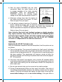
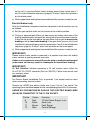
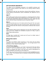
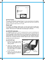
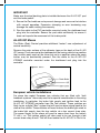
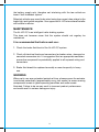
0 10 5 100 95 90 80 70 60 50 40 30 20 10 5 100 95 90 80 70 60 50 40 30 20 10 5 100 95 90 80 70 60 50 40 30 20 10 5 100 95 90 80 70 60 50 40 30 20 10 5 100 95 90 80 70 60 50 iQ7 XTREME IN CAR KIT Installation & Operating Instructions 40 30 20 10 5 100 95 90 80 70 60 50 40 AL-KO INTERNATIONAL ABN 96 003 086 813 FOR DETAILS OF YOUR NEAREST AL-KO AUTHORISED SERVICE AGENT PLEASE CONTACT OUR STATE OFFICES AS LISTED BELOW: VICTORIA 67-91 NATHAN ROAD, DANDENONG STH, VICTORIA 3175 TELEPHONE: (03) 9767 3700 FACSIMILE: (03) 9792 0877 NEW SOUTH WALES 26 HALLSTROM PLACE WETHERILL PARK, NEW SOUTH WALES 2164 TELEPHONE: (02) 8784 9400 FACSIMILE: (02) 9725 4557 QUEENSLAND 13 UNION Circuit, YATALA, QUEENSLAND 4207 TELEPHONE: (07) 3386 6300 FACSIMILE: (07) 3386 6399 NEW ZEALAND 1 AIRPARK DRIVE, AIRPARK OAKS MANGERE, AUCKLAND TELEPHONE: (09) 255 5611 FACSIMILE: (09) 255 5612 This information MUST be distributed with the AL-KO iQ7 trailer braking system and be kept with the towing vehicle for future reference. PLEASE READ WIRING INSTRUCTIONS AS IMPORTANT CHANGES HAVE BEEN MADE. The AL-KO iQ7 XTREME Controller incorporates a number of unique features designed to maximise the performance of your braking system. Auto Detect The AL-KO iQ7 XTREME incorporates an ‘Auto Detect’ function that enables it to identify which type of braking system has been connected and alters its electronic signal automatically in order to achieve maximum brake performance. When in Electric Brake mode (if installed) the LED on the mouse is orange. The intensity will increase as braking increases. In AL-KO iQ7 XTREME mode the LED on the mouse is green and will change to orange when brakes are applied. The intensity will increase as braking increases. IMPORTANT! If changing between trailers utilising varying actuator types (i.e. AL-KO iQ7 XTREME to Electric), the tow vehicle power supply will need to be turned off then turned on again to enable trailer detection. Controller Components Brake Pad The patented AL-KO iQ7 XTREME Pad is mounted onto the brake pedal of the tow vehicle. A pressure sensitive film incorporated into the pad measures the force being applied in a braking situation and converts this into a variable voltage signal. Mouse The AL-KO iQ7 XTREME Mouse is to be mounted in the cab of the towing vehicle within easy reach of the driver. The mouse serves a number of functions: Panic Button - The panic button provides an antisway function. Should the trailer get into a sway the panic button is pressed, applying a light braking force to the trailer independent to the towing vehicle. The brakes will be applied lightly for 3 seconds only and should assist in the straightening of the trailer. The tow vehicle & trailer stop lights are also activated. Variable Gain Control - Enables the driver of the towing vehicle to set the amount of trailer braking from within the cab. Ideally the gain should be set so as the towing vehicle and trailer brake together. Excessive braking of the trailer will result in premature wearing of the trailers brake shoes/pads. 1 AL-KO iQ7 XTREME Controller (ECU) The AL-KO iQ7 XTREME continually monitors the state of the electric system to ensure safe operation. The early detection of potential faults are all continually monitored with the driver informed of any such fault through the AL-KO iQ7 mouse (audible and visual signals). Wiring Loom The AL-KO iQ7 XTREME Wiring Loom has been specially designed to simplify the installation process and is outlined in figure 1. Figure 1. Generic Wiring Diagram INSTALLATION Towing Vehicle Note: It is recommended that all in-vehicle electrical work is undertaken by a registered auto electrician, and that the bare copper conductors to pins 8, 10, 11, 12 are not soldered before fitting. IMPORTANT! 1.The iQ7 XTREME must be installed with a 12 volt negative ground system 2.The iQ7 XTREME must be mounted away from all other electronic control devices e.g. electric throttle control. 3.Route all wires as far from the radio antenna as possible to reduce AM interference. It is critical that when installing the AL-KO iQ7 XTREME Controller that the factory supplied wiring loom is used. 4.Should additional wire be required make sure that it is of similar or larger gauge than supplied. Under no circumstances should wire thinner than the factory supplied loom be used as this may affect product performance and void the warranty. 5.The collection of water inside the electrical trailer connection will reduce the life of the connector and may result in inadequate or intermittent braking. To minimise corrosion build up inside the connector, it is suggested that an appropriate corrosion preventative compound be applied to conductive surfaces. Refer to maintenance section. 2 MAINTENANCE: The AL-KO iQ7 is an intelligent trailer braking system that has onboard diagnostic software. Should the system detect a fault, the operator will be informed via a visual and audible alarm inside the tow vehicle. This does not however mean that the system should not regularly be maintained. It is suggested that before each use: 1.Check the brake fluid level of the AL-KO iQ7 system. 2.Check all electrical leads and connectors for broken wires, damaged or corroded connectors etc. It is suggested that an appropriate corrosion preventive compound be periodically applied to all exposed wiring and connectors. 3.Always ensure the trailer plug and socket are kept in good working condition. They must be kept clean and dry to prevent electrical leakage that may cause the trailer brakes to provide indequate or intermittent braking. 4.Brake fluid should be replaced annually or more frequently in heavy use. WARNING: When not in use over extended periods of time, please ensure the actuator is activated periodically (approximately every four weeks) to ensure moving components remain in good operating condition and seals remain lubricated. Failure to do so may result in incorrect product performance and could result in serious damage or injury. FAULT SIGNALS Constant beeping and flashing Situation: Actuator pressure has not been reached, trailer disconnected while ignition still on, low voltage alarm, or excessive moisture in trailer socket causing short circuit. Four beeps/flashes at one second intervals followed by rest period of 4 seconds (repeats for 10 minutes) Situation: Compressor has been operating for more than 200 seconds continuously (will not operate for 10 minutes while cooling). VERIFYING ELECTRICAL INSTALLATION After completion of electrical installation it is important to verify correct installation using the following procedure. For this test the trailer needs to be connected to the vehicle a)With the engine RUNNING measure the voltage at the tow vehicle battery. 3 b)With the engine RUNNING and the trailer connected, apply the trailer brakes so as to engage operation of the trailer mounted compressor. While the compressor is RUNNING measure the actuator supply voltage at the trailer plug across pin 8 & pin 10. c)Maximum voltage drop from the battery to the trailer plug must not exceed 1.5 volts. Refer to figure 2 for pin layout. Figure 2. Socket Wiring Vehicle Socket Female (Vehicle) Pin No. 8 10 11 12 Colour Red Black Brown Blue Function 12 Volt Power Supply (+ve) Earth (-ve) Fault Signal Control Voltage (Pin No's 11 & 12 refer to Sensabrake™ hydraulic actuator only) 12 4 11 7 2 10 3 9 5 8 6 1 12 Pin Socket d)If the battery voltage is less than 12 volts the battery should be tested, and all electrical connections between the battery, AL-KO iQ7 XTREME controller, and trailer plug checked for correct operation and repaired or replaced where necessary. Refer to figure 2 for pin layout. Note: Vehicles fitted with fault feedback systems or digital signaling may require isolation relays fitted to the AL-KO iQ7 XTREME ignition and brake light supplies. Power and earth supplies must come direct from the battery. This should ensure that the AL-KO iQ7 XTREME controller is independent of the vehicles electronics. TESTING Hydraulic AL-KO iQ7 Actuator only After the Initialisation sequence has been completed, test the system set-up as follows: a)Turn on the ignition. The mouse will produce the ‘fault signal’ indicating that a sufficient pressure has not yet been achieved in the actuator. This signal will last for approximately 30 - 40 seconds until a working pressure has been reached. The compressor will however remain on after the signal has stopped, until working full pressure has been achieved (approx. 90 -100 seconds). b)Once the ‘fault signal’ has stopped, wait a further 60 seconds before undertaking brake proportionality testing. Find an appropriate stretch of road where brake testing can be undertaken without the disruption of other road users. c)Set the gain control slider on the mouse to the middle position. d)Driving at approximately 50km per hour apply the brakes. Take note of the braking proportionality between the towing vehicle and the towed vehicle. If they are not similar then adjust the gain slider to the right for more trailer braking or left for less trailer braking. If the gain slider is 4 set on full (+) and insufficient trailer braking occurs then repeat steps 1 and 2 in the initialisation sequence (page 6). At step 2 place less pressure on the brake pedal. e)When proportional braking has been established the system is ready for use. Electric Brakes only After the Initialisation sequence has been completed, test the system set-up as follows: a)Set the gain control slider on the mouse to the middle position. b)Driving at approximately 50km per hour apply the brakes take note of the braking proportionality between the towing vehicle and the towed vehicle. If they are not similar then adjust the gain slider to the right for more trailer braking or left for less trailer braking. If the gain slider is set on full (+) and insufficient trailer braking occurs then repeat steps 1 and 2 in the initialisation sequence (page 6). At step 2 place less pressure on the brake pedal. c)When proportional braking has been established the system is ready for use. IMPORTANT! Please ensure trailer socket is mounted in a position that does not enable water contact or pooling around terminals. Under no circumstances should the trailer plug or socket be submerged under water as this may result in inadequate or intermittent braking. IMPORTANT! 24 Volt Vehicles: Vehicles operating a 24 volt system must utilize the AL-KO iQ7 24-12VDC converter (Part no. 350015). Failure to do so will void any warranty claim. IMPORTANT For Electric Brake Installation Only, a separate 7 pin socket must be used when connecting electric brakes. Connect the LARGE blue electric brake wire to pin 5 of the 7 pin socket. The remaining 6 pins should be looped into the corresponding pins of the 12 pin socket. UNDER NO CIRCUMSTANCES SHOULD THE ELECTRIC BRAKE WIRE (BLUE) BE CONNECTED TO THE 12 PIN SOCKET. Pin No. 8 10 11 12 Colour Red Black Brown Blue Function 12 Volt Power Supply (+ve) Earth (-ve) Fault Signal Control Voltage 5 INITIALISATION SEQUENCE The object of the initialisation sequence is to establish minimum and maximum braking pressure limits based on the towing vehicles braking characteristics. This sequence need only be undertaken during initial installation, however should braking characteristics require modification the sequence can be repeated. Step 1: Set the Mouse gain to the minimum position (i.e. far left) and start the vehicle with panic button pressed down (simultaneously). DO NOT have your foot on the brake pedal when starting the vehicle. Two short beeps and two flashes from the mouse indicates you are in calibration mode. Step 2: Place light pedal pressure on the brake pedal at the point that you require maximum trailer braking and press the panic button. Three beeps and three flashes indicate that the maximum brake pressure calibration has occurred correctly. Note: If the maximum brake pressure calibration is set too high, insufficient trailer braking will occur. Repeat the initialisation sequence. At Step 2 place a lighter brake pedal pressure. Note: All steps have ‘sensible limit’ checks and will revert to default values if expected values are not found. Wiring Description Earth The black wire labelled “Earth” (ground) is to be wired into the towing vehicles 12 volt (-ve) terminal of the battery - at no stage should it be connected to the chassis or vehicle body. 12 Volt Power Supply The red wire labelled “Battery +ve 12 volt’ is to be wired into the towing vehicles 12 volt (+ve) terminal of the battery. The 30 amp resettable circuit breaker as supplied and fitted to the loom must also be incorporated as close as possible to the battery on this supply line. The 30 amp circuit breaker should be secured to a non-conductive surface of the vehicle. The terminals must be insulated using electrical insulating tape or similar. 6 RED to EVO BLACK to EVO 30 amp resettable circuit breaker 12 volt battery Ignition Supply The yellow wire labelled “Ignition Supply” is to be wired direct to the lighter socket supply line or similar. This power supply must only be live after the ignition is turned on and must be 12 volts. Brake Light The orange wire labelled “Brake Light’ is to be wired into the brake light circuit between the brake light switch and the brake lights of the towing vehicle. This must be 12 volts when the brake light is activated. AL-KO iQ7 Controller It is suggested that the AL-KO iQ7 is attached firmly under the dashboard of the towing vehicle using cable ties (or similar) so as not to interfere with the normal operation of the vehicle and so as to protect the components and connectors. This must be as far as possible from the vehicle’s electronic control units including electronic throttle control units in order to prevent possible electrical interference. AL-KO iQ7 Pad 1.Remove the brake pad rubber from the brake pedal of the towing vehicle. Figure 4. iQ7 Pad iQ7 Pad 2.Using the template from the back page of this manual drill the two 5.5mm holes through the brake pedal as indicated on the template. Brake pedal 3.Attach the AL-KO iQ7 pad to the brake pedal and secure as shown in figure 4. Backing plate 7 IMPORTANT Make sure the steel backing plate is installed between the AL-KO iQ7 pad and the brake pedal! 4.Secure the Pad cable so as to prevent damage and so as not to interfere with normal operation. Excessive clamping or over tensioning may damage the cable voiding the warranty. 5.Run the cable to the EVO controller mounted under the dashboard and plug into the controller. Secure the pad cable sufficiently to ensure it does not impede the movement of the brake pedal. AL-KO iQ7 Mouse The Slider (Gain) Control provides additional ‘instant’ user adjustment of control sensitivity. Remove the outer surface of the adhesive tape on the back of the AL-KO iQ7 mouse. Firmly secure to the dashboard of the towing vehicle in a position that is within easy reach of the driver but not in a position where the panic button may be accidentally pressed. Run the cable to the AL-KO iQ7 XTREME controller mounted under the dashboard and plug into the controller. Figure 5. Mouse European vehicle installations For some late model European tow vehicles that are fitted with “fault feedback systems” there may need to be special consideration in the wiring installation. In particular, the brake light supply and ignition feed to the AL-KO iQ7 XTREME controller from the Tow vehicle. These vehicles are likely to run a digital “Bus” system that will send an alarm signal back to the dash of the vehicle. These vehicles will need to have the brake light wired to the brake light supply from the tow vehicle via a low current draw relay. The power supply to the relays will need to come direct from the battery 12 volt + ve. The ignition supply will also need to be run through a low current draw relay as well. This will then isolate the AL-KO iQ7 In Car kit to 8 the battery supply only, therefore not interfering with the tow vehicle on board “fault feedback system”. Selected vehicles may need to be wired using low current draw relays to the brake light and ignition supplies. Your approved AL-KO International installer will be able to advise. Maintenance The AL-KO iQ7 is an intelligent trailer braking system. This does not however mean that the system should not regulary be maintained. It is recommended that before each use: 1. Check the brake fluid level of the AL-KO iQ7 system. 2. Check all electrical leads and connectors for broken wires, damaged or corroded connectors etc. It is suggested that an appropriate corrosion preventive compound be periodically applied to all exposed wiring and connectors. 3. Brake fluid should be replaced annually or more frequently in heavy use. WARNING When not in use over extended periods of time, please ensure the actuator is activated periodically (approximately every four weeks) to ensure moving components remain in good operating condition and seals remain libricated. Failure to do so may result in incorrect product performance and could result in serious damage or injury. 9 AL-KO INTERNATIONAL PTY LTD WARRANTY authorised repair agent where the claim is not covered by this warranty. Our goods come with guarantees that cannot be excluded under the Australian Consumer Law. You are entitled to a replacement or refund for a major failure and for compensation for any other reasonably foreseeable loss or damage. You are also entitled to have the goods repaired or replaced if the goods fail to be of acceptable quality and the failure does not amount to a major failure. AL‑KO International Pty Ltd (ABN 96 003 066 813) (“AL‑KO”) provides the following warranty in relation to its AL‑KO iQ7 XTREME Actuator, AL‑KO iQ7 Actuator and In Car Kit (“Product”). The benefits of this warranty are in addition to any rights and remedies imposed by Australian State and Federal legislation that cannot be excluded. Nothing in this warranty is to be interpreted as excluding, restricting or modifying any State or Federal legislation applicable to the supply of goods and services which cannot be excluded, restricted or modified. EXCLUSIONS The warranty will not apply where: (a) the Product has been repaired, altered or modified by someone other than AL‑KO or an authorised repair agent; (b) AL‑KO cannot establish any fault in the Product after testing and inspection; (c) the Product has been used other than for the purpose for which it was designed; (d) the defect in the Product has arisen due to the customer’s failure to properly use and maintainthe Product in accordance with AL‑KO’s instructions, recommendations and specifications (including maintenance); (e) the Product has been subject to abnormal conditions, including environment, temperature, water, fire, humidity, pressure, stress or similar; (f) the defect has arisen due to abuse, misuse, neglect or accident; or (g) unauthorised parts or accessories have been used on or in relation to the Product. WARRANTY AL‑KO warrants that, subject to the exclusions and limitations below, the Product will be free from defects in materials and workmanship for a period of 12 months from the date of installation. This warranty is not transferable to a subsequent person if the Product is sold by the original purchaser during the warranty period. If a defect appears in the Product before the end of the warranty period and AL‑KO finds the Product to be defective in materials or workmanship, AL‑KO will, in its sole discretion, either: (a) replace or repair the Product or the defective part of the Product free of charge; or (b) cause the Product or the defective part of the Product to be replaced or repaired by a qualified repairer free of charge. AL‑KO reserves the right to replace defective parts of the Product with parts and components of similar quality, grade and composition where an identical part or component is not available. Goods presented for repair may be replaced by refurbished goods of the same type rather than being repaired. Refurbished parts may be used to repair the goods. LIMITATIONS AL‑KO makes no express warranties or representations other than set out in this warranty. The repair or replacement of the Product or part of the Product is the absolute limit of AL‑KO’s liability under this express warranty. EXTENDED AL-KO WARRANTY AL‑KO International will extend the warranty for a further 24 months (therefore the warranty will be valid for 36 months from date of installation) where the following conditions are satisfied: (a) the Brake Controller/In Car Kit has been installed by an AL‑KO International approved installer*; (b) the customer has completed the warranty form on the Product instruction manual and sent it back to AL‑KO International for registration; (c) the customer has attached to the completed warranty form a copy of the original installation invoice provided to the customer by the AL‑KO International approved installer*; (d) the copy of the original installation invoice clearly shows the date of installation and the details of the AL‑KO International approved installer*; (e) The Brake Controller is an AL‑KO approved Motion Sensing Controller (see page 6); and the Actuator AL‑KO iQ7 has been installed by an approved OEM manufacturer. If anything listed in (a) to (f) above is not complied with then AL‑KO International reserves the right to limit the warranty to a 12 month period. (*) A list of the approved installers is available at www.alkoiQ7.com.au Failure to comply with the installation and verification instructions may result in incorrect operation or premature product failure that could lead to serious injury, accident, or death and will also void this product warranty. WARRANTY CLAIMS 1. If a fault covered by warranty occurs ‘ the customer must first contact AL‑KO at the contact address listed below, or the retailer from which the Product was purchased. 2. Any warranty claim must be accompanied by: (a) proof of purchase; (b) full details of the alleged defect; and (c) any relevant documentation (such as maintenance records). 3. The customer must make the Product available to AL‑KO or its authorised repair agent for inspection and testing. If inspection and testing finds no defect in the Product, the customer must pay AL‑KO’s costs of service work and testing. 4. AL‑KO will bear the cost of the transport of the Product to and from AL‑KO or the authorised repair agent where the defect is covered by this warranty. AL‑KO will organise for the transport at the time the claim is made. The customer must bear the cost of the transport from AL‑KO or the CONTACT AL‑KO International Pty Ltd 67 Nathan Road, Dandenong South, VIC, 3175 Phone: (03) 9767 3700. Email: [email protected] 8 10 8 Template for SB06 AUTO PEDAL Template for SB05 MANUAL PEDAL Boat State, Province Dealer Address State, Province City Dealer Name City Phone: 61 3 9767 3700 Fax: 61 3 9792 0877 Email: [email protected] Web: www.alko.com.au Address Return to: AL-KO International Pty Ltd ABN 96 003 066 813 67-91 Nathan Road Dandenong South Victoria 3175 Australia Other Yes No P/Code P/Code Gross Vehicle Mass (GVM) of towed vehicle Caravan Name Average km per year towing trailer InstalledbyDealer Friend Recommended Model Owned before DatePurchased Horse Dealer Other Transport Ad SerialNo.ALK Prior brand if this is a replacement: Type of trailer: Type of tow vehicle: Make Model To register your purchase, please complete the form below and return to the AL-KO address below. Product Warranty Registration Card 0 60 50 40 30 20 10 5 100 95 90 80 70 60 50 40 30 20 10 5 100 95 90 80 70 60 50 40 30 20 10 5 100 95 90 80 70 60 50 40 30 20 10 5 100 95 90 80 70 60 50 40 30 20 10 5 100 95 90 80 70 60 50 40 30 20 10 5 100 95 90 80