1
Show/Hide Bookmarks
EDB2102UB
00417816
Operating Instructions
LECOM A/ B
Fieldbus module type 2102
RS232, RS485, optical fibre
Show/Hide Bookmarks
These Operating Instructions are valid for fieldbus modules with the following nameplates:
2102
2102
2102
IB.
IB.
IB.
2x.
2x.
2x.
3x.
3x.
3x.
V001
V002
V003
(RS232, RS485)
(RS485)
(Optical fibre)
In connection with the unit series as from the nameplate data:
820X
E.
2x.
1x.
820X
E./C. 2x.
1x.
821X
E.
2x.
2x.
821X
E./C. 2x.
2x.
822X
E.
1x.
1x.
822X
E.
1x.
1x.
824X
E.
1x.
1x.
824X
E./C. 1x.
1x.
82EV
VA
0x
8200 vector
82EV
1x
0x
8200 vector
93XX
E.
2x.
1x.
93XX
E./C. 2x.
1x.
(8201 - 8204)
Vxxx
(8201 - 8204)
Vxxx
(8211 - 8218)
(8211 - 8218)
(8221 - 8225)
Vxxx
(8221 - 8227)
Vxxx
(8241 - 8246)
(8241 - 8246)
(9321 - 9333)
Vxxx
(9321 - 9333)
Type
Design:
E = Built-in unit IP20
IB = Module
Hardware level and index
Software level and index
Version
Explanation
Important:
These Operating Instructions are only valid together with the corresponding Instructions for
82XX, 8200 vector or 93XX controllers.
.
1998 Lenze GmbH & Co KG
Without written approval of Lenze GmbH & Co KG this documentation or part of it may not be copied or passed on to third parties.
All information given in this documentation have been checked for compliance with the hardware and software described. Nevertheless, deviations and
mistakes cannot be ruled out. We do not take any responsibility or liability for damages which might possibly occur. Necessary corrections will be included
in the next edition.
Version
1.0
10/00
Show/Hide Bookmarks
Contents
1 Preface and general information . . . . . . . . . . . . . . . . . . . . . . . . . . . . . . . . . . . . . . . . . . .
1-1
1.1
About these Operating Instructions . . . . . . . . . . . . . . . . . . . . . . . . . . . . . . . . . . . . . . . . . . . . . . . . . . . .
1.1.1
Terminology used . . . . . . . . . . . . . . . . . . . . . . . . . . . . . . . . . . . . . . . . . . . . . . . . . . . . . . . . .
1.1.2
What is new? . . . . . . . . . . . . . . . . . . . . . . . . . . . . . . . . . . . . . . . . . . . . . . . . . . . . . . . . . . . .
1-1
1-1
1-1
1.2
Packing list . . . . . . . . . . . . . . . . . . . . . . . . . . . . . . . . . . . . . . . . . . . . . . . . . . . . . . . . . . . . . . . . . . . . .
1.2.1
Legal regulations . . . . . . . . . . . . . . . . . . . . . . . . . . . . . . . . . . . . . . . . . . . . . . . . . . . . . . . . . .
1-1
1-2
2 Safety information . . . . . . . . . . . . . . . . . . . . . . . . . . . . . . . . . . . . . . . . . . . . . . . . . . . . . .
2-1
2.1
Persons responsible for safety . . . . . . . . . . . . . . . . . . . . . . . . . . . . . . . . . . . . . . . . . . . . . . . . . . . . . . .
2-1
2.2
General safety information . . . . . . . . . . . . . . . . . . . . . . . . . . . . . . . . . . . . . . . . . . . . . . . . . . . . . . . . . .
2-1
2.3
Layout of the safety information . . . . . . . . . . . . . . . . . . . . . . . . . . . . . . . . . . . . . . . . . . . . . . . . . . . . . .
2-2
3 Technical data . . . . . . . . . . . . . . . . . . . . . . . . . . . . . . . . . . . . . . . . . . . . . . . . . . . . . . . . .
3-1
3.1
Features of the 2102 fieldbus module . . . . . . . . . . . . . . . . . . . . . . . . . . . . . . . . . . . . . . . . . . . . . . . . . .
3-1
3.2
General data and application conditions . . . . . . . . . . . . . . . . . . . . . . . . . . . . . . . . . . . . . . . . . . . . . . . .
3-1
3.3
Rated data . . . . . . . . . . . . . . . . . . . . . . . . . . . . . . . . . . . . . . . . . . . . . . . . . . . . . . . . . . . . . . . . . . . . . .
3-2
3.4
Dimensions . . . . . . . . . . . . . . . . . . . . . . . . . . . . . . . . . . . . . . . . . . . . . . . . . . . . . . . . . . . . . . . . . . . . .
3-2
3.5
Communication times . . . . . . . . . . . . . . . . . . . . . . . . . . . . . . . . . . . . . . . . . . . . . . . . . . . . . . . . . . . . .
3-3
4 Installation . . . . . . . . . . . . . . . . . . . . . . . . . . . . . . . . . . . . . . . . . . . . . . . . . . . . . . . . . . . .
4-1
4.1
Connections of the 2102 fieldbus module . . . . . . . . . . . . . . . . . . . . . . . . . . . . . . . . . . . . . . . . . . . . . . .
4.1.1
Overview . . . . . . . . . . . . . . . . . . . . . . . . . . . . . . . . . . . . . . . . . . . . . . . . . . . . . . . . . . . . . . . .
4.1.2
Female plug for 9-pole SubD plug (LECOM-A/B) . . . . . . . . . . . . . . . . . . . . . . . . . . . . . . . . . . .
4.1.3
Plug-in terminal for 4-pole male plug (LECOM-B) . . . . . . . . . . . . . . . . . . . . . . . . . . . . . . . . . .
4.1.4
Plug-in terminal for 2-pole male plug (external voltage supply) . . . . . . . . . . . . . . . . . . . . . . . .
4-1
4-1
4-2
4-2
4-2
4.2
Mechanical installation . . . . . . . . . . . . . . . . . . . . . . . . . . . . . . . . . . . . . . . . . . . . . . . . . . . . . . . . . . . . .
4-3
4.3
Electrical installation . . . . . . . . . . . . . . . . . . . . . . . . . . . . . . . . . . . . . . . . . . . . . . . . . . . . . . . . . . . . . .
4-3
4.4
Wiring to a host . . . . . . . . . . . . . . . . . . . . . . . . . . . . . . . . . . . . . . . . . . . . . . . . . . . . . . . . . . . . . . . . . .
4.4.1
Wiring via RS232 (LECOM-A) . . . . . . . . . . . . . . . . . . . . . . . . . . . . . . . . . . . . . . . . . . . . . . . . .
4.4.2
Wiring via RS485 (LECOM-B) . . . . . . . . . . . . . . . . . . . . . . . . . . . . . . . . . . . . . . . . . . . . . . . . .
4.4.3
Wiring via optical fibres (LECOM-LI) . . . . . . . . . . . . . . . . . . . . . . . . . . . . . . . . . . . . . . . . . . . .
4-4
4-5
4-6
4-8
5 Commissioning . . . . . . . . . . . . . . . . . . . . . . . . . . . . . . . . . . . . . . . . . . . . . . . . . . . . . . . .
5-1
BA2102EN
i
Show/Hide Bookmarks
Contents
6 Parameter setting . . . . . . . . . . . . . . . . . . . . . . . . . . . . . . . . . . . . . . . . . . . . . . . . . . . . . .
6-1
6.1
Parameter sets . . . . . . . . . . . . . . . . . . . . . . . . . . . . . . . . . . . . . . . . . . . . . . . . . . . . . . . . . . . . . . . . . .
6.1.1
82XX parameter sets . . . . . . . . . . . . . . . . . . . . . . . . . . . . . . . . . . . . . . . . . . . . . . . . . . . . . . .
6.1.2
Parameter sets for 8200 vector . . . . . . . . . . . . . . . . . . . . . . . . . . . . . . . . . . . . . . . . . . . . . . .
6.1.3
Parameter sets for 93XX . . . . . . . . . . . . . . . . . . . . . . . . . . . . . . . . . . . . . . . . . . . . . . . . . . . .
6-1
6-1
6-1
6-1
6.2
Meaning of individual parameters . . . . . . . . . . . . . . . . . . . . . . . . . . . . . . . . . . . . . . . . . . . . . . . . . . . . .
6.2.1
Operating mode . . . . . . . . . . . . . . . . . . . . . . . . . . . . . . . . . . . . . . . . . . . . . . . . . . . . . . . . . . .
6.2.2
LECOM unit address (C0009) . . . . . . . . . . . . . . . . . . . . . . . . . . . . . . . . . . . . . . . . . . . . . . . . .
6-2
6-2
6-3
6.3
Special features when using the 82XX controller . . . . . . . . . . . . . . . . . . . . . . . . . . . . . . . . . . . . . . . . . .
6.3.1
Start with Ctrl. inhibit instead of QSP . . . . . . . . . . . . . . . . . . . . . . . . . . . . . . . . . . . . . . . . . . .
6.3.2
Reduction of the response time of the interface . . . . . . . . . . . . . . . . . . . . . . . . . . . . . . . . . . .
6.3.3
Communication monitoring . . . . . . . . . . . . . . . . . . . . . . . . . . . . . . . . . . . . . . . . . . . . . . . . . .
6-4
6-4
6-4
6-4
6.4
Special features when using the 820X controllers . . . . . . . . . . . . . . . . . . . . . . . . . . . . . . . . . . . . . . . . .
6.4.1
Relative setpoint selection C0141 (parameter channel) . . . . . . . . . . . . . . . . . . . . . . . . . . . . . .
6.4.2
Special features when using the 820X V1.2 controller . . . . . . . . . . . . . . . . . . . . . . . . . . . . . . .
6-5
6-5
6-5
6.5
Special notes for 821X, 822X, 824X controllers . . . . . . . . . . . . . . . . . . . . . . . . . . . . . . . . . . . . . . . . . . .
6-6
6.6
Special notes when using 8200 vector controllers . . . . . . . . . . . . . . . . . . . . . . . . . . . . . . . . . . . . . . . . .
6-6
7 Troubleshooting and fault elimination . . . . . . . . . . . . . . . . . . . . . . . . . . . . . . . . . . . . . . .
7-1
8 Appendix . . . . . . . . . . . . . . . . . . . . . . . . . . . . . . . . . . . . . . . . . . . . . . . . . . . . . . . . . . . . .
8-1
ii
8.1
Accessories . . . . . . . . . . . . . . . . . . . . . . . . . . . . . . . . . . . . . . . . . . . . . . . . . . . . . . . . . . . . . . . . . . . . .
8.1.1
Accessories for a host . . . . . . . . . . . . . . . . . . . . . . . . . . . . . . . . . . . . . . . . . . . . . . . . . . . . . .
8.1.2
Accessories for RS232 (LECOM-A) . . . . . . . . . . . . . . . . . . . . . . . . . . . . . . . . . . . . . . . . . . . . .
8.1.3
Accessories for RS485 (LECOM-B) . . . . . . . . . . . . . . . . . . . . . . . . . . . . . . . . . . . . . . . . . . . . .
8.1.4
Accessories for optical fibres (LECOM-LI) . . . . . . . . . . . . . . . . . . . . . . . . . . . . . . . . . . . . . . . .
8-1
8-1
8-1
8-2
8-2
8.2
Code table . . . . . . . . . . . . . . . . . . . . . . . . . . . . . . . . . . . . . . . . . . . . . . . . . . . . . . . . . . . . . . . . . . . . . .
8-3
8.3
LECOM-A/B protocol . . . . . . . . . . . . . . . . . . . . . . . . . . . . . . . . . . . . . . . . . . . . . . . . . . . . . . . . . . . . . .
8.3.1
General . . . . . . . . . . . . . . . . . . . . . . . . . . . . . . . . . . . . . . . . . . . . . . . . . . . . . . . . . . . . . . . . .
8.3.2
RECEIVE . . . . . . . . . . . . . . . . . . . . . . . . . . . . . . . . . . . . . . . . . . . . . . . . . . . . . . . . . . . . . . . .
8.3.3
SEND . . . . . . . . . . . . . . . . . . . . . . . . . . . . . . . . . . . . . . . . . . . . . . . . . . . . . . . . . . . . . . . . . .
8.3.4
BROADCAST / MULTICAST . . . . . . . . . . . . . . . . . . . . . . . . . . . . . . . . . . . . . . . . . . . . . . . . . . .
8.3.5
Monitoring of the slave response . . . . . . . . . . . . . . . . . . . . . . . . . . . . . . . . . . . . . . . . . . . . . .
8.3.6
Transmission faults . . . . . . . . . . . . . . . . . . . . . . . . . . . . . . . . . . . . . . . . . . . . . . . . . . . . . . . .
8-16
8-16
8-21
8-23
8-24
8-24
8-24
8.4
List of abbreviations . . . . . . . . . . . . . . . . . . . . . . . . . . . . . . . . . . . . . . . . . . . . . . . . . . . . . . . . . . . . . . .
8-25
8.5
Glossary . . . . . . . . . . . . . . . . . . . . . . . . . . . . . . . . . . . . . . . . . . . . . . . . . . . . . . . . . . . . . . . . . . . . . . .
8-26
8.6
Table of keywords . . . . . . . . . . . . . . . . . . . . . . . . . . . . . . . . . . . . . . . . . . . . . . . . . . . . . . . . . . . . . . . .
8-27
BA2102EN
Show/Hide Bookmarks
Preface and general information
1
Preface and general information
1.1
About these Operating Instructions
• These Operating Instructions are intended for safety-relevant operations on and with the 2102
fieldbus module. They contain safety information which must be observed.
• All personnel working on and with the 2102 fieldbus module must have these Operating
Instructions available and observe the information and notes relevant for them.
• The Operating Instructions must always be complete and perfectly readable.
These Operating Instructions inform about the most important technical data and the installation of
the 2102 fieldbus module. They are only valid in combination with the Operating Instructions of the
corresponding controller.
1.1.1
Terminology used
Controller
In the following, the term ”controller” is used for ”93XX servo inverters” or ”82XX frequency inverters”.
Drive system
In the following the term ”drive system” is used for drive systems with fieldbus modules and other Lenze
drive components.
Fieldbus module
In the following text the term ”fieldbus module” is used for ”fieldbus module type 2102 RS232, RS485,
optical fibre”.
Cxxx/y
L-Cxxx/y
Subcode y of code Cxxx (e.g. C0410/3 = subcode 3 of code C0410)
Lenze code
Xk/y
Terminal strip Xk/terminal y (e.g. X3/28 = terminal 28 on terminal strip X3)
( xx-yyy)
Cross reference (chapter - page)
^
1.1.2
1.2
What is new?
Ident. no.
edition of
Important
391 845
08/1996
1st edition
394 448
02/1997
replaces 391 845
• extended by 2102.V904, 2102.V905, 2102.V906
• Chapter 6.3
• Editorially reviewed
404 788
417 816
11/1998
10/2000
replaces 394 448
replaces 404 788
Format change to DIN A4
• Adaptation to 8200 vector (all chapters)
Packing list
Packing list
• 1 2102 fieldbus module with housing (enclosure IP20)
• 1 M3 fixing screw
• 1 two-pole male connector for voltage supply
• 1 Short Instructions
Instr ctions
Contents
BA2102EN
Important
After the delivery has received, check immediately whether the items
supplied match the accompanying papers. Lenze does not accept any
liability for deficiencies claimed subsequently.
Claim
• visible transport damage immediately to the forwarder
• visible deficiencies/incompleteness immediately to your
yo r Lenze
representative.
1-1
Show/Hide Bookmarks
Preface and general information
1.2.1
Legal regulations
Labelling
g
Nameplate
CE identification
Lenze 2102 fieldbus modules are
In compliance with to the EC Low Voltage
unambiguously identified by their nameplates. Directive
Application as
directed
2102 fieldbus module
• Operate the fieldbus module only under the conditions prescribed in these Operating Instructions.
• The fieldbus module is an additional module and can be optionally attached to the Lenze controller series 820X, 821X, 822X, 8200 vector
and 93XX. The 2102 fieldbus module links these Lenze controllers to superimposed hosts (PLC or PC) using the Lenze LECOM A/B/LI
fieldbuses.
• The fieldbus module must be attached and electrically connected so that it complies with its function and does not cause any hazards when
attached and operated as instructed.
• Observe all notes given in chapter “Safety information“ ( 2-1).
• Please observe all information given in these Operating Instructions. This means:
– Read these Operating Instructions carefully before you start to work with the system.
– These Operating Instructions must always be available during operation of the fieldbus module.
Any other use shall be deemed inappropriate!
Manufacturer
Lenze GmbH & Co KG
Postfach 101352
D-31763 Hameln
^
Liability
• The information, data, and notes in these instructions met the state of the art at the time of printing. Claims referring to drive systems
which have already been supplied cannot be derived from the information, illustrations, and descriptions given in these Operating
Instructions.
• The specifications, processes, and circuitry described in these Operating Instructions are for guidance only and must be adapted to your
own specific application. Lenze does not take responsibility for the suitability of the process and circuit proposals.
• The indications given in these Operating Instructions describe the features of the product without warranting them.
• Lenze does not accept any liability for damage and operating interference caused by:
– disregarding these Instructions
– unauthorized modifications to the controller
– operating faults
– improper working on and with the controller
Warranty
• Warranty conditions: see Sales and Delivery Conditions of Lenze GmbH & Co KG.
• Warranty claims must be made immediately after detecting defects or faults.
• The warranty is void in all cases where liability claims cannot be made.
Disposal
p
Material
Metal
Plastic
Printed-board assemblies
Operating Instructions
1-2
recycle
-
-
BA2102EN
dispose
-
-
Show/Hide Bookmarks
Safety information
2
Safety information
2.1
Persons responsible for safety
Operator
• An operator is any natural or legal person who uses the drive system or on behalf of whom the drive system is used.
• The operator or his safety personnel is obliged
– to ensure the compliance with all relevant regulations, instructions and legislation.
– to ensure that only skilled personnel works on and with the2102IB fieldbus module.
– to ensure that the personnel has the Operating Instructions available for all corresponding work.
– to ensure that all unqualified personnel are prohibited from working on and with the drive system.
Qualified personnel
Qualified personnel are persons who - because of their education, experience, instructions, and knowledge about corresponding standards and regulations, rules for
the prevention of accidents, and operating conditions - are authorized by the person responsible for the safety of the plant to perform the required actions and who are
able to recognize potential hazards.
(Definition for qualified personnel to VDE 105 or IEC 364)
2.2
•
•
•
•
•
•
•
•
•
General safety information
These safety notes do not claim to be complete. In case of questions and problems please contact your Lenze representative.
At the time of delivery the fieldbus module meets the state of the art and ensures basically safe operation.
The indications given in these Operating Instructions refer to the stated hardware and software versions of the fieldbus modules.
The fieldbus module is hazardous if:
– unqualified personnel works on and with the fieldbus module.
– the fieldbus module is used inappropriately.
The processing notes and circuit sections shown in these Operating Instructions are proposals which cannot be transferred to other applications without being
tested and checked.
Ensure by appropriate measures that neither personal injury nor damage to property may occur in the event of failure of the fieldbus module.
The drive system must only be operated when no faults occur.
Retrofittings, modifications, or redesigns are basically prohibited.Lenze must be contacted in all cases.
The fieldbus module is electrical equipment intended for use in industrial high-power plants. The fieldbus module must be tightly screwed to the corresponding
controller during operation. In addition, all measures described in the Operating Instructions of the controller used must be taken. Example: Fasten covers to ensure
protection against contact.
BA2102EN
2-1
Show/Hide Bookmarks
Safety information
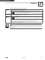
2.3
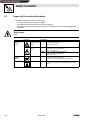
Layout of the safety information
• All safety information have a uniform layout:
– The icon characterizes the type of danger.
– The signal word characterizes the severity of danger.
– The note text describes the danger and gives information on how to prevent dangerous
situations.
Signal word
Note
Icons used
Warning of
damage to
persons
Warning of
hazardous electrical
voltage
Signal words
Danger!
Warns of impending danger.
Consequences if disregarded:
Death or severe injuries.
Warning of a general Warning!
danger
Caution!
2-2
Warning of
damage to
material
Stop!
Other notes
Tip!
BA2102EN
Warns of potential, very hazardous situations.
Possible consequences if disregarded:
Death or severe injuries.
Warns of potential, hazardous situations.
Possible consequences if disregarded:
Light or minor injuries.
Warns of potential damage to material.
Possible consequences if disregarded:
Damage of the controller/drive system or its environment.
This note designates general, useful notes.
If you observe it, handling of the controller/drive system is made
easier.
Show/Hide Bookmarks
Technical data
3
Technical data
3.1
Features of the 2102 fieldbus module
The 2102 fieldbus module has the following features:
• Different communication media:
– RS232 (LECOM-A)
– RS485 (LECOM-B)
– Optical fibre (LECOM-LI)
• LECOM protocol V2.0
• The baud rate can be set to 1200, 2400, 4800 9600 or 19200 baud (bit/s).
• Parameter setting via controller code numbers
• 3 Diagnostic LEDs
• Electrical isolation between control stage and power stage
• Electrical isolation of the I/O terminals of 821X, 8200 vector, 822X and 93XX
• Easy installation
3.2
General data and application conditions
Field
Communication media
Values
RS232 (LECOM-A): copper conductor
RS485 (LECOM-B): copper conductor
(LECOM-LI): optical fibre
Protocol
Character
Format
LECOM-A/B V2.0
7 bit ASCII
1 Stop bit
1 Start bit
1 Parity bit (even)
1200, 2400, 4800, 9600, 19200
During operation:
0
Transport:
–25
Storage:
–25
Baud rate [bits/s]
Ambient temperature
to
to
to
+ 50 C
+ 70 C
+ 55 C
Permissible moisture
Class 3K3 to EN 50178 (without condensation, average relative humidity 85%)
24-V-DCVoltage supply
• 820X / 8200 vector (observe chapter 4.3):
• 821X / 822X / 8200 vector (observe chapter 4.3) / 93XX:
BA2102EN
only external supply
internal or external supply
3-1
Show/Hide Bookmarks
Technical data
3.3
Rated data
2102IB.V001
RS232 (LECOM-A)
RS485 (LECOM-B)
Communication media
Current consumption
External supply
(terminals 39/59)
80 mA
V = 24 V DC
URMS = 15 TO 30 V DC; W = 5 %
URMS = 20 TO 25 V DC; W = 48 %; VSS < 35 V
Insulation voltages
to PE
for external supply
(terminal 39/59)
50 V AC
for power stage
820X:
821X:
8200 vector:
822X:
93XX:
for the control terminals
820X:
0 V AC
8200 vector (with internal supply):
0 V AC
821X:
50 V AC
8200 vector (with external supply):
100 V AC
822X:
270 V AC
93XX:
270 V AC
2102IB.V002
RS485 (LECOM-B)
2102IB.V003
Optical fibre
(LECOM-LI)
60 mA
70 mA
0 V AC (no electrical isolation)
Degree of pollution
270 V AC
270 V AC
270 V AC
270 V AC
270 V AC
(single basic insulation)
(single basic insulation)
(double basic insulation)
(double basic insulation)
(double basic insulation)
(no electrical isolation)
(no electrical isolation)
(Electrical isolation)
(single basic insulation)
(single basic insulation)
(single basic insulation)
VDE 0110 part 2 pollution degree 2
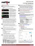
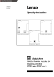
3.4
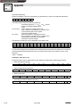
Dimensions
Fig. 3-1
Dimensions of the 2102 fieldbus module (all dimensions in mm)
3-2
BA2102EN
Show/Hide Bookmarks
Technical data
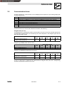
3.5
Communication times
The time required for communication can be displayed as a sequence of processing steps (with
corresponding times).
Step
t0
t1
t2
t3
t4
t5
t6
Explanation
User program in host starts request to the controller (e.g. controller enable with C0040= 1)
Software driver (e.g. LECOM-S5) in host converts request data into LECOM-A/B protocol V2.0 and starts the transmission.
Serial data transfer to the controller (telegram time)
Data receipt of the controller: Processing of request and start of response
Response data to host are being transmitted (telegram time)
Software driver in host evaluates the response, i.e. the response is converted into the format of the user program.
Application program in host gets the result
The time sections t2, t4 and t3 are described in detail in the following:
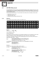
Telegram time (t2 + t4)
The telegram time comprises the serial communication from the host to the controller (t2) and the
corresponding response from the controller (t4). The time depends on the telegram type and the
baud rate set under C0125.
Baud rate [bits/s] (C0125)
Single character transmission time [ms]
(1 character = 10 bit; see chapter 3.2)
1200
8.4
2400
4.2
1200
150
41.6
2400
75
20.8
4800
2.1
9600
1
19200
0.52
Telegram type SEND (sends data to drive):
Baud rate [bits/s] (C0125)
t2: Standard [ms] (parameter value = 9 characters)
Addition for extended addressing [ms]
4800
37.5
10.4
9600
18.8
5.2
19200
9.4
2.6
Telegram type RECEIVE (reads data from drive):
Baud rate [bits/s]
Standard [= t4]
(Parameter value = 9 characters) [ms]
Addition for extended addressing [ms]
1200
166.7
2400
83.3
4800
41.7
9600
20.8
19200
10.4
83.3
41.7
20.8
10.4
5.2
If more or fewer than 9 characters are transmitted as telegram data, take the corresponding
character-transmission times into account.
BA2102EN
3-3
Show/Hide Bookmarks
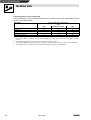
Technical data
Processing time in the controller (t3)
The processing time in the controller depends on the controller type and the code numbers. This is
shown in the following table:
Code numbers
Processing time (2102 + controller) [ms]
Series
C0046, C0135
C0050, C0150
C0068
Write other code numbers
Read other code numbers
821X/8200 vector/822X
20
20
30
20 2)
20
93XX
20 3)
20
30
20 4)
20
1)
35 ms is valid for C0001 = 3. If C0001 = 1 and you write under C0046, access is also possible. However, the processing time is prolonged
to 70 ms.
2)
For immediately following write-access procedures, the response times may be up to 50ms.
The code number C0046 can only be read. Use a free code number (e. g. C0141) to select a setpoint. For this, refer to the 93XX Manual.
This is a typical value. For some codes, the processing times may be longer. For this, refer to the 93XX Manual.
3)
4)
3-4
820X
35 1)
35
70
230
55
BA2102EN
Show/Hide Bookmarks
Installation
4
Installation
4.1
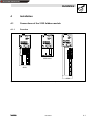
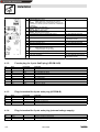
Connections of the 2102 fieldbus module
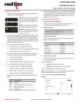
4.1.1
Overview
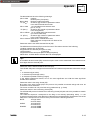
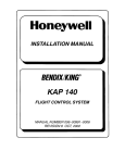
8200 vector
82XX
93XX
Fig. 4-1
82XX, 8200 vector and 93XX controllers (with fieldbus module 2102)
BA2102EN
4-1
Show/Hide Bookmarks
Installation
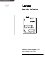
Pos.
1
2
3
4
5
6
7
8
9
10
11
12
-
Fig. 4-2
4.1.2
Pin
1
2
3
4
5
6
7
8
9
Name
RxD
TxD
DTR
GND
DSR
T/R(A)
T/R(B)
Vcc5
4-2
only with 2102IB.V903/2102.V906
only with 2102IB.V903/2102.V906
only with 2102IB.V903/2102.V906
only with 2102IB.V901/2102.V904 and
2102IB.V902/2102.V905
Input/output
Input
Output
Output
Input
Input/output
Input/output
Output
Explanation
Not assigned
Data receiving wire RS232
Data transmitting wire RS232
Transmission control RS232
Reference potential
Not assigned RS232
RS485
RS485
Supply + 5 V / 10 mA
Plug-in terminal for 4-pole male plug (LECOM-B)
Name
T/R(B)
T/R(A)
S-C
S
4.1.4
Pin
39/
59/
Operating status display for the controller
Optical-fibre transmitter (white)
Optical-fibre receiver (black)
Switch S1 for optical-fibre transmission rate:
OFF:
normal transmission rate (0 to 40m)
ON:
= high transmission rate (10 to 66m)
Connection for external voltage supply (24 V DC ± 10 %)
PE connection (only for 82XX)
RS 485 cable (no drawing)
Female plug for 9-pole SubD plug (LECOM-A/ B)
4.1.3
Pin
71
72
88
89
Name/Meaning
Note
Green bus LED (voltage supply)
ON:
Fieldbus module has connected with the controller.
BLINKING: 2102 fieldbus module is supplied with voltage but is not
connected to the controller (controller is switched off, in initialization or
not available).
Yellow RxD-LED For receiving signal:
BLINKING: Drive unit receives telegram
Yellow TxD-LED For sending signal:
BLINKING: Drive unit transmits response
9-pole SubD female plug for the RS232/RS485 interface
only with 2102IB.V901/2102.V904
Fixing screw
4-pole clamp-plug connection for RS485 interface
only with 2102IB.V901/2102.V904 and
2102IB.V902/2102.V905
Input/output
Input/output
Input/output
-
Explanation
RS485
RS485
Capacitive screening to PE
Direct screening to PE
Plug-in terminal for 2-pole male plug (external voltage supply)
Name
GND24
Vcc24
Input/output
Input
Explanation
Reference potential for external supply
External supply 15 to 30 V DC (see chapter 4.3 )
BA2102EN
Show/Hide Bookmarks
Installation
4.2
Mechanical installation
• Remove the keypad from the front of the controller if it is attached.
• Attach the 2101 fieldbus module to the front of the controller. Use the fixing screw, which is
part of the delivery package, to secure the fieldbus module (see Fig. 4-1, pos. 3) (^ 1-1).
Stop!
Tighten the fixing screw to ensure adequate PE connection of the 2102 fieldbus module.
4.3
Electrical installation
• The communication of controllers 820X and 821X may be disturbed by electromagnetic
radiation.Use an additional PE cable to ensure safe communication
(see Fig. 4-1 pos. 13).
This is not necessary with the controllers 822X and 93XX.
Caution!
The bus system continues operation even if the 2102 fieldbus system is disconnected from the
power supply because of an error.
If this is the case, the controller cannot be reached by the host.
Stop!
The polarity of the voltage supply must not be reversed, otherwise, the 2102 fieldbus module will
be destroyed !
• Voltage supply:
– external 24 V (15 to 30 V) via plug-in connectors 39 (-) / 59 (+)
or
– internal via the controller (connection by plugging it on).
With 820X it is not possible to have an internal voltage supply via the controller.
BA2102EN
4-3
Show/Hide Bookmarks
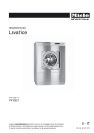
Installation
Note!
Internal voltage supply of the fieldbus module connected to a 8200 vector
Controllers with an extended AIF interface (front of the 8200 vector) can be internally supplied. The
part of the drawing highlighted with grey shows the jumper position.
In Lenze setting, the fieldbus module is not internally supplied.
For internal voltage supply, put the jumper in the position indicated below.
Lenze setting
Internal voltage supply
(only external voltage supply)
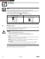
4.4
Wiring to a host
This chapter informs you about networking the 2102 fieldbus module using the bus systems RS232
(LECOM-A), RS485 (LECOM-B) or optical fibres (LECOM-LI).
The accessories requires are listed in chapter 8.1.
Danger!
• An additional electrical isolation is required if
– a 820X, 821X or 8200 vector controller will be connected to a host
– a safe electrical isolation (double basic insulation) to VDE 0160 is required.
• Please observe the following:
– RS232:
The electrical isolation of the RS232 interface (LECOM-A) can be achieved by two 2101IB
level converters or another RS232 electrical isolation.
– RS485:
With RS485 (LECOM-B), the 2101IB level converter should be installed to the host if it is
not equipped with an appropriately isolated interface.
– Optical fibres:
If two controllers are connected via optical fibres (LECOM-LI) they are always isolated.
• For wiring, the electrical isolation of the supply voltage must be taken into account.
The controllers 822X and 93XX are equipped with a double basic insulation to VDE 0160 and,
additional electrical isolation is therefore not necessary.
4-4
BA2102EN
Show/Hide Bookmarks
Installation
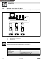
4.4.1
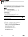
Wiring via RS232 (LECOM-A)
The following figure schematically shows the connection to a host (here: PC)via RS232 (LECOM-A).
6
LEMOC
1
PC system cable
Fig. 4-3
Wiring for RS232 (LECOM-A)
Wiring features for RS232 (LECOM-A):
Type
Communication media
Network topology
Possible number of controllers
Maximum cable length
Maximum baud rate
2102IB.V001
RS232
Point-to-point
1
15 m
19200 bit/s
Note!
We recommend the use of ready-made PC system cables for wiring (see chapter 8.1.2).
Wire the PC system cables as described:
1. Use metallic SubD connector shells and connect both ends of the screen to the connector
shells.
2. Connect the pins as follows:
Unit
Connection element
2102 fieldbus module
9-pole SubD plug
2 (RxD)
3 (TxD)
5 (GND)
9-pole SubD female plug
3 (TxD)
2 (RxD)
5 (GND)
25-pole SubD female plug.
2 (TxD)
3 (RxD)
7 (GND)
Host (PC,
(PC PLC,
PLC etc
etc.))
BA2102EN
Pin-No. (name)
4-5
Show/Hide Bookmarks
Installation
4.4.2
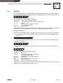
Wiring via RS485 (LECOM-B)
The following figure schematically shows the connection to a host (PC or PLC) via RS485
(LECOM-B).
RS232
RS485
3
S1
S1
5939 71728889
RS485
5939 71728889
1
Fig. 4-4
2a
S1
RS485
5939 71728889
RS485
4
2101IB
2b
1
Wiring for RS485 (LECOM-B)
ó
Interface cable RS485
Optional
O
tional host connection
a) directly RS485
b) RS232 via interface converter 2101IB
PC system cable
ì
ö
2101IB interface converter
Note!
• We recommend the use of appropriate accessories (see chapter 8.1.3).
• Please do not use any other but a shielded and twisted cable for wiring the RS485 interface
cable.
Wiring features for RS485 (LECOM-B):
4-6
Type
2102IB.V002
Communication media
RS485 (2 wires)
Network topology
Line
Possible number of controllers
31
Maximum cable length
1200 m
Maximum baud rate
19200 bit/s
BA2102EN
Show/Hide Bookmarks
Installation
PC/PLC
T/R/(A)
T/R/(B)
PE
71 72 88 89
Fig. 4-5
71 72 88
2102
2102
Controller
1
Controller
2
Connection to the host (PC/PLC)
Connection between two controllers (cable 1 in Fig. 4-4):
• Connect the cable shield with terminal 89 (direct PE) of one fieldbus module and terminal 88
(capacitive PE) of the other fieldbus module (Fig. 4-5).
This method prevents currents flowing through the cable screens.
• Connect the terminals 71 and 72 between the fieldbus modules via paired cables (e.B. green
and yellow).
Direct connection to the host (cable 2a in Fig. 4-4)
• Connect the host cable screen to PE and the controller cable screen to terminal 88.
This method prevents currents flowing through the cable screens.
Connection to the 201IB interface converter (cable 2b in Fig. 4-4):
PC/PLC
RxD
72
TxD
71
PE
88
71 72 88 89
71 72 88 89
2102
2102
2101IB interface converter
Controller
1
Fig. 4-6
Controller
2
Connection to the 2101IB interface converter
• Connect the cable shield with terminal 89 (direct PE) of the last controller and terminal 88
(capacitive PE) of the interface converter (Fig. 4-6).
This method prevents currents flowing through the cable screens.
BA2102EN
4-7
Show/Hide Bookmarks
Installation
4.4.3
Wiring via optical fibres (LECOM-LI)
The following figure schematically shows the connection to a host (PC or PLC) via optical fibre
(LECOM-LI).
RS232
1
Optical fibre
ON
S1
S1
OFF
ON
S1
S1
OFF
5939
Fig. 4-7
2
ON
S1
S1
OFF
5939
5939
Wiring for optical fibres (LECOM-LI)
ó
RS232/optical fibre-converter for hosts
Optical-fibre cable
Note!
We recommend the use of appropriate accessories (see chapter 8.1).
Wiring features for optical fibres (LECOM-LI):
4-8
Type
2102IB.V003
Communication media
Optical fibre (plastic)
Network topology
Ring
Possible number of controllers
52
Maximum cable length
0 to 40 m for standard transmission rate (S1 = OFF)
10 to 66 m for high transmission rate (S1 = ON)
Maximum baud rate
19200 bit/s
BA2102EN
Show/Hide Bookmarks
Installation
For wiring, optical-fibre cables must be prepared:
Optical-fibre cable
preparation
The preparation of the optical-fibre cables does not require special tools.
1. Cut cable to length on a rigid surface, e.g. using a knife.
2. For optical-fibre cables with PUR sheaths (read) remove approx. 20 mm (for cables with PE sheaths, removal is not required).
With unpolished optical-fibre ends, the max. length is reduced by approx. 20 %.
Therefore, polish the cable end of the optical fibre (grain: P1000).
Installation of
optical-fibre cables
1. Open pinch-screw joint of the plug.
2. Insert the cable end into the optical-fibre connection as far as possible.
3. Tighten the pinch-screw joint.
The bending radius should be at least 30 mm, otherwise the max. optical-fibre cable length will be reduced by typically
50 % per bend.
Installation of the
optical-fibre ring
(Fig. 4-7)
1. Connect the white optical-fibre connector (transmitter, TxD) on the host to the black optical-fibre connector (receiver, RxD) on the next
controller.
2. Connect the white optical-fibre connector on the controller to the black optical-fibre connector on the next controller.
3. Connect the white optical-fibre connector on the last controller to the black optical-fibre connector on the host.
4. If the optical-fibre cables are longer than 40 m, select the high transmission rate. Switch S1 to ON position. This provides a maximum
cable length of 66 m (with a damping of 150 dB/km).
Note!
Further information on LECOM-LI can be obtained from the Operating Instructions LECOM-LI (see
chapter 8.1.4).
BA2102EN
4-9
Show/Hide Bookmarks
Installation
4-10
BA2102EN
Show/Hide Bookmarks
Commissioning
5
Commissioning
Stop!
Before switching on the mains voltage check the wiring for completeness, short circuit and earth
fault.
When switching on the unit for the first time, observe the following sequence:
1. Switch on the controller and, if necessary, the external supply of the 2102 fieldbus module.
– The operating status display for the controller ((^ 4-2), Fig. 4-2 pos. 5) must be on or
blinking.
– The green LED ((^ 4-2), Fig. 4-2 pos. 8) must be on. If this is not the case, see chapter 7.
2. The transmission speed or LECOM baud rate (C0125)is factor set to 9600 baud. If you require
a different value, adjust it via the operating unit.
3. Set LECOM unit address (C0009; see description in chapter 6.2.2) via the operating unit or via
the host (default setting: 1).
– If several controllers are interconnected, the addressing via C0009 of the controller must be
different than that of the others. This is the only way for the host to reach a certain
controller.
– The values 00, 10, 20, 30, ¡, 90 must not be set since they are reserved for group
addressing.
Tip!
The code numbers C0009 (LECOM controller address) and C0125 (LECOM baud rate) can also be
input via LECOM. Please observe that the parameters for the host must be adapted. If C0125 is
changed, the host will not recognize the response because the controller already transmits it with
the new baud rate.
Next steps for 82XX / 8200 vector
1. It is now possible to communicate with every controller, i.e. all code numbers can be read
and all writeable codes, except C046 (frequency setpoint) and C0135 (control word) can also
be changed.
If the code numbers C0046 and C0135 are to be preselected as well, set C0001 = 3.
2. If the controller is switched on while the operating mode C0001 = 3 is active and the speed
setpoint is set to =0, QSP (quick stop) is active. Thus, the drive cannot start in an uncontrolled
way. The QSP function can be deactivated by setting bit3 from C0135 to 0.
BA2102EN
5-1
Show/Hide Bookmarks
Commissioning
Next steps for 93XX
1. Now you can communicate with each drive, i.e. you can read all codes and change all
writeable codes.
2. Set the Lenze parameter signal configuration (C0005) to a value xxx1 to control the controller.
For the first commissioning, select the signal configuration 1011 (speed control).
3. Terminal 28 (ctrl. enable=controller enable) is always active and must be on HIGH level during
operation (see Operating Instructions 93XX). Otherwise, the controller cannot be enabled.
– With the signal configuration C0005=1011, the QSP function (quick stop) and the CW/CCW
changeover are assigned to the input terminals E1 and E2, and thus they are always active.
During operation, E1 must be at HIGH level (see Operating Instructions 93XX).
Tip!
With the signal configuration C0005=xx11, terminal A1 is switched as voltage output. Thus, only the
following terminals can be connected via cables:
X5.A1 with X5.28 (ctrl. enable)
X5.A1 with X5.E1 (R/QSP)
4. With signal configuration 1011 (speed control), the speed setpoint can be selected in % of
nmax under C0141.
5-2
BA2102EN
Show/Hide Bookmarks
Parameter setting
6
Parameter setting
The parameter setting for the 2102 fieldbus module comprises:
• Controller parameters which can also be set with the operating units 8201BB or 9371BB.
• 2102 parameters, which can only be accessed via the 2102 fieldbus module.
Only the controller parameters are permanently saved in the corresponding controller.
Only the parameters important for the serial communication are listed in the following and in the
code table (see chapter 8.2). For further information about the parameter setting see the Manual or
the Operating Instructions of the controllers.
6.1
Parameter sets
6.1.1
82XX parameter sets
The 82XX controller is equipped with 2 directly addressable parameter sets. They are addressed by
means of a code-digit offset:
• Offset 0 addresses parameter set 1 with the codes C0000 to C1999.
• Offset 2000 addresses parameter set 2 with the codes C2000 to C3999.
If a parameter is only available once (see Operating Instructions 82XX), use the code-digit offset 0.
Example:
C011 = maximum field frequency
C011 in parameter set 1: code number = 11
C011 in parameter set 2: code number = 2011
Changes of the parameters are automatically saved in the controller (see Operating Instructions
82XX).Process data, for instance control words or setpoints are excluded.
6.1.2
Parameter sets for 8200 vector
The 8200 vector controllers are equipped with 4 directly addressable parameter sets. They are
addressed by means of a code-digit offset:
• Offset 0 addresses parameter set 1 with the codes C0000 to C1999.
• Offset 2000 addresses parameter set 2 with the codes C2000 to C3999.
• Offset 4000 addresses parameter set 1 with the codes C4000 to C5999.
• Offset 6000 addresses parameter set 2 with the codes C6000 to C7999.
If a parameter is only available once (see 8200 vector Operating Instructions), use code offset 0.
Example:
C011 = maximum field frequency
C011 in parameter set 1: code number = 11
C011 in parameter set 2: code number = 2011
C011 in parameter set 3; code number = 4011
C011 in parameter set 4; code number = 6011
Changes of the parameters are automatically saved in the controller (see Operating Instructions
8200 vector). Process data, for instance control words or setpoints are excluded.
6.1.3
Parameter sets for 93XX
The 93XX controllers are equipped with 4 parameter sets for non-volatile storage. Another
parameter set is in the user memory of the controller. This is the current parameter set. Only the
current parameter set can be directly addressed. Codes: See Operating Instructions or Manual
93XX. Changes of the current parameter set will be lost after switching off the controller. Code C0003
is for saving the current parameter set. After switching on the controller, parameter set 1 is
automatically loaded into the current parameter set.
BA2102EN
6-1
Show/Hide Bookmarks
Parameter setting
6.2
Meaning of individual parameters
6.2.1
Operating mode
82XX / 8200 vector controllers
Code C0001 (operating mode) determines the source (terminal, keypad, LECOM) which writes the
frequency setpoint (C0046) and the control word (C0135).
Independently of the selected operating mode C0001, the controller can be inhibited under C0040
via LECOM.
Tip!
Please note that the operating mode C0001 is available in both parameter sets. Thus, C0001 must
be set identically in both parameter sets.
For LECOM control (C0001 = 3), the operating mode in parameter set 1 applies 1. For terminal
control (C0001 <> 3), the operating mode in parameter set 1 and parameter set 2 applies.
93XX controllers
The 93XX controller does not offer an operating mode which can be changed by only one code - as
available in the 82XX controller. The 93XX controller is operated via the so-called ”Control codes”.
If, for instance, the speed setpoint is to be changed via LECOM, it is necessary to define a control
code as source for the speed setpoint input of the speed controller. Select the configuration of the
control code so that you can enter the speed setpoint via the 2102 fieldbus module. For further
information please refer to the Manual 93XX.
6-2
BA2102EN
Show/Hide Bookmarks
Parameter setting
6.2.2
LECOM unit address (C0009)
The LECOM-A/B protocol uses the LECOM unit address to address the controller. The LECOM unit
address is set under code C0009 at the controller. The address must only be used once. Thus, each
controller must get its own LECOM unit address.The values 00, 10, 20, 30, ..., 90 must not be set
since they are reserved for group addressing (see chapter 5).
The LECOM-A/B protocol enables controller groups. This allows a write request to be issued to
several drives at the same time, e.g. to select new setpoints or enable or inhibit the controller. Select
via the following reserved LECOM unit addresses:
LECOM unit address C0009 for
group drives
LECOM unit addresses of the addresses controllers
00
10
20
30
40
50
60
70
80
90
all
11 to 19
21 to 29
31 to 39
41 to 49
51 to 59
61 to 69
71 to 79
81 to 89
91 to 99
Tip!
Please note that with LECOM controller addresses which end with a 0, the controller does not return
an acknowledgement, i.e. the host does not recognize whether the controller received the data
correctly or not.
BA2102EN
6-3
Show/Hide Bookmarks
Parameter setting
6.3
Special features when using the 82XX controller
Tip!
Reading and writing of the parameter C192x of 82XX controllers takes up to 500 ms.
6.3.1
Start with Ctrl. inhibit instead of QSP
• After mains connection with the operating mode C0001 = 3, the drive is in the status QSP.
• With C1920 = 1, the switch-on status is always Ctrl. inhibit, so that the drive can be enabled
by writing C0040 = 1.
Code
Name
Note
C1920
Start status
0
1
QSP
Controller inhibit
(P2102)
LECOM format: VD
6.3.2
Reduction of the response time of the interface
• With active reduced response time, write telegrams (send) are only checked for transmission
errors:
– If the telegram is fault-free, a positive acknowledgement (ACK) is sent, otherwise it is a
negative acknowledgement (NAK).
– Only then the value to be written is transmitted to the controller.
• The module can be readdressed under the following conditions:
– With 820X controllers after approx. 230 ms.
– With 821X/8200vector/822X controllers after approx. 50 ms.
Stop!
The acceptance of the value by the controller cannot be guaranteed.
Code
Name
Note
C1921
Shortened response time
0
1
Not active
active
(P2102)
LECOM format: VD
6.3.3
Communication monitoring
• The fieldbus module can monitor the communication connection to the host.
• If the host does not send a telegram to the fieldbus module within the monitoring time set
under C1923, the measure set under C1922 will be carried out.
Code
Name
Note
C1922
Monitoring selection
code
0
1
2
Not active
Controller inhibit
QSP (quick stop)
(P2102)
LECOM format: VD
C1923
6-4
Monitoring time
50 to 65535ms
(P2102)
LECOM format: VD
BA2102EN
Show/Hide Bookmarks
Parameter setting
6.4
Special features when using the 820X controllers
• Parameter setting (codes except C0046, C0135) is only possible while the controller is
inhibited. Parameters are accepted during controller enable but not saved.
• The TRIP reset function (fault reset) is executed by setting controller inhibit followed by
controller enable via code C0040 or C0135.
– The TRIP-reset function performs basic initialization of the 820X controller and the 2102
fieldbus module. Therefore, the TRIP reset command is not acknowledgedto the host, thus
causing its telegram monitoring to react.
6.4.1
Relative setpoint selection C0141 (parameter channel)
• Enter a relative setpoint, which refers to C0011, under C0141.
• Independently of the currently set parameter, C0011 of parameter set 1 is always taken as
reference value.
• The automatic adaption of the relative setpoint in the event of a C0011 change is not
considered because C0011 can only be changed when the controller is inhibited.
6.4.2
Code
Name
Note
C0141
Frequency setpoint
0 to 100 %
(P2102)
LECOM format: VD
Special features when using the 820X V1.2 controller
Code
Name
Note
C0120
C0181
Window for hysteresis output fdact = fdset
Code not available
0 to 80 %
(P2102)
LECOM format: VD
BA2102EN
6-5
Show/Hide Bookmarks
Parameter setting
6.5
Special notes for 821X, 822X, 824X controllers
Relative setpoint selection C0127 (process and parameter channel)
• Absolute setpoint selection
A setpoint is input as absolute Hz value via the process and the parameter channel:
Process channel:
Setpoint absolute ± 24000
Parameter channel:
C046
C141
480 Hz
absolute in Hz
no influence
• Normalized setpoint selection
A setpoint is input as absolute C0011 value via the process and parameter channel:
Process channel:
Setpoint absolute ± 214
Parameter channel:
C046
C141
C011 (fdmax)
only display absolute in Hz
± 100.00% C011 (fdmax)
Code
Name
Note
C0127
Frequency setpoint selection format
0
1
Absolute setpoint selection
Normalized setpoint selection
(P2102)
LECOM format: VD
6.6
Special notes when using 8200 vector controllers
The digital and analog input and output signals can be configured freely (see Operating Instructions
vector; codes C0410, C0412, C0417 and C0421).
6-6
BA2102EN
Show/Hide Bookmarks
Troubleshooting and fault elimination
7
Troubleshooting and fault elimination
LED yellow (RxD)
LED green (Vcc)
LED yellow (TxD)
Operating-state display of
the controller
Fig. 7-1
Fault
^ 4-2) )
LEDs on the fieldbus module 2102IB (see Fig. 4-2 page (
Cause
Controller is switched off.
Display:
• none of the operating-state displays is lit-up
and/or
• green Vcc-LED is blinking
Remedy
Supply controller with voltage (see corresponding Operating Instructions)
2102IB fieldbus module is not supplied with voltage
Display:
green Vcc-LED is not flashing or blinking.
• With internal supply from the controller, check the connection to the
The 2102IB fieldbus module has not been initialized with the controller
Display:
green Vcc-LED is blinking.
• Supply controller with voltage (see corresponding Operating
controller.
• With external supply, check the voltage at terminals 39 and 59. A
voltage between 15 and 30 V must be applied (see chapter 4.3)
The controller does not receive telegrams.
No commu- For a test, let the host send telegram cyclically. This happens, for
instance, with LEMOC2 in online operation.
nication
The yellow RxD-LED must blink when the host sends a telegram.
with the
controller.
The controller does not send telegrams.
For a test, let the host send telegram cyclically. This happens, for
instance, with LEMOC2 in online operation.
The yellow TxD-LED must blink when the controller send a telegram to
the host.
Instructions)
• Check the connection to the controller.
If the yellow RxD-LED does not blink:
• Check the wiring (see chapter 4.4)
and
• Test whether the host sends telegrams and uses the appropriate
interface.
1. Yellow TxD-LED is not blinking:
Parameter for LECOM unit address (C0009) and LECOM baud rate (C0125)
must be the same at the controller and the host. Check the parameters
C0009 and C0125 at both units and set them to the same value if
necessary.(Controller-address parameters 00, 10, , 90 must not be
used.)
¡
2. Yellow TxD-LED is blinking:
• The LECOM unit addresses (C0009) must be different at all connected
controllers. Correct possibly occurring double addressing.
• Check the wiring to your host.
• With self-developed LECOM-A/B software drivers and RS485
operation, observe the transmission control. After transmitting signals,
the host must return to receive mode after approx. 1 ms.
Controller
d
does
not
execute
write job
1. Controller sends negative acknowledgement (NAK response):
• The operating mode C0001 is set incorrectly for write access to codes • Set parameter 3 for operating mode C0001.
C0046 and C0135.
• The code is defined so that it can only be read.
• In general, write job not possible.
2. Controller sends positive acknowledgement (ACK response):
• With 820X, parameters can only be changed when the controller is
inhibited (see chapter 6.3).
• Activate controller inhibit
• Controller uses a different parameter set
• Changeover of the parameter set; the parameter change is then
activated.
BA2102EN
7-1
Show/Hide Bookmarks
Troubleshooting and fault elimination
7-2
BA2102EN
Show/Hide Bookmarks
Appendix
8
Appendix
8.1
Accessories
8.1.1
Accessories for a host
In the following you will find the accessory components for hosts (PC or PLC):
Name
LEMOC2
Order no.
EW00388233
Explanation
PC program for drive programming;
System requirements: IBM AT compatible
Operating Instructions
LECOM-S5
33.2164
Communication processor for Siemens-SIMATIC-S5 AG 115U, 135U, 150U, 155U
LECOM-PC
-
LECOM-A/B communication driver for PC systems in C/C+ + (source code).
A modification for other target systems can be easily achieved.
LECOM-PN
B&R
Mitsubishi
Schleicher
Sigmatek
Cotas
AMS
-
Driver for PC the visualisation system PROCON produced by gti
Drivers for various PLC systems.
Further information on request.
8.1.2
Accessories for RS232 (LECOM-A)
In the following you will find the accessory components for RS232 (LECOM-A):
Name
PC system cable 5 m
Order no.
EW00338094
Explanation
between fieldbus module 2102IB and PC
(9pole socket)
PC system cable 10 m
EW00338095
between fieldbus module 2102IB and PC
(9pole socket)
Specification for RS232 interface cables
Cable type
Cable resistance
Capacitance per unit length
Length
LIYCY 4 x 0.25 mm2 shielded
100 Ω/km
140 nF/km
$ 15 m
BA2102EN
8-1
Show/Hide Bookmarks
Appendix
8.1.3
Accessories for RS485 (LECOM-B)
In the following you will find the accessory components for RS485 (LECOM-B):
Name
Order no.
Interface converter 2101IB 33.2101IB
PC system cable 5 m
EW00338094
Specification for RS485-interface cable
with a length of up to 300 m:
Cable type
Cable resistance
Capacitance per unit length
Length
with a length of up to 1200 m:
Cable type
Cable resistance
Capacitance per unit length
Length
8.1.4
Explanation
Level converter between RS232 and RS485/RS422 with electrical isolation
System cable between PC (9-pole female connector) and 2101IB interface converter
LIYCY 1 x 2 x 0.5 mm2 shielded
40 Ω/km
130 nF/km
300 m
$
$
$
CYPIMF 1 x 2 x 0.5 mm2 shielded
40 Ω/km
60 nF/km
1200 m
$
$
$
Accessories for optical fibres (LECOM-LI)
In the following you will find the accessory components for optical fibres (LECOM-LI):
Name
2125
Order no.
33.2125IB
Explanation
Optical fibre/RS232 converter for hosts
normal transmission rate (0 to 40m)
2126
33.2126IB
Optical fibre/RS232 converter for hosts
high transmission rate (10 to 66m)
Plug-in power supply unit
Operating Instructions LECOM-LI
Optical fibre 1ADR with PE sheath
Optical fibre 1ADR with PUR sheath
EJ0362016
EDLECOM-LI/D
EW00359679 (by the meter)
EW00359681 (by the meter)
Plug-in power supply unit 220V/9V DC for 2125 and 2126
Basics and installation of LECOM-LI
Optical-fibre cable with black PE sheath (standard protection)
Optical-fibre cable with red PUR sheath (reinforced protection)
Specification for optical fibre cables
Field
Min. bending radius
Max. tensile force
Electric strength
Operating temperature
Wave length
Damping
Cable length between two participants (cable
damping = 150dB/km)
Values
30 mm
100 N
110 kV/m
40 to 80 C
660 nm
100 to 400 dB/km
0 to 40 m (normal transmission rate)
10 to 66 m (high transmission rate)
Fibre core
Material/diameter
Polymethylmethacrylat (PMMA) / 976 µm
Fibre sheath
Material/diameter
Flurorpolymer / 1000 µm
Outer sheath
Material/diameter
Thermoplast polyester (PE) / 2.2 mm
8-2
BA2102EN
Show/Hide Bookmarks
Appendix
8.2
Code table
How to read the code table:
Code
Code number of the parameter
Leading zeros are not required.
Codes marked with * are only available in parameter set 1.
Name
Name of the parameter
The text in parenthesis informs whether the codes are available in the fieldbus module or the
controller:
(P2102): Parameters in the fieldbus module 2102IB
(P820X/P821X/8200 vector/822X):
Parameters in controllers 820X, 821X and 822X.
The parameters can also be set via the 8201BB keypad.
(P93XX):Parameters in the 93XX controller.
The parameters can also be set via the 9371BB keypad.
Contents and meaning of the parameter Parameters printed in bold are set by Lenze.
values
Parameters
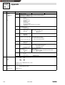
Code
C0001
Name
Operating
p
g mode for
• 82XX
• 8200 vector
(P82XX)
Note
82XX
0 Control (C0135):
Setpoint (C0046):
(Lenze setting: 0)
1 Control (C0135):
Setpoint (C0046):
2 Control (C0135):
Setpoint (C0046):
3 Control (C0135):
Setpoint (C0046):
8200 vector
see Operating Instructions ’Vector’
Terminal
Terminal
Terminal
Keypad:
Terminal
Terminal
LECOM
LECOM
The operating mode defines the source which
writes on a parameter.
The keypad and LECOM always have the right to
parameterize.
C0009*
LECOM controller
address
LECOM format: VD
1
1 to 99
Controller address for unique address in a LECOM-A/B/LI network.
Do not set the values 00, 10, ..., 90, since they are reserved for group addressing.
(P82XX)
C0040*
(P93XX)
LECOM format: VD
Controller inhibit
0
Controller inhibited
1
Controller enabled
Parameter C0040 is independent of operating mode C0001.
The controller can also be enable with control word C0135.
(P2102)
LECOM format: VD
C0043*
TRIP reset for:
• 821X
• 8200 vector
• 822X
• 93XX
C0046*
Frequency setpoint for:
• 820X
(P2102)
(P2102)
Frequency setpoint for:
• 821X
• 8200 vector
• 822X
0
No actual fault, fault reset by overwriting with
value 0
1
Actual fault
Parameter C0043 is independent of operating mode C0001. A TRIP can also be reset using the control word C0135. (TRIP
reset for 820X, see chapter 6.4)
LECOM format: VD
0 to 480 Hz
LECOM format: VD
0 to 480 Hz
The value can be changed through the display factor C500/C501 (see Code table included in the Operating Instructions 820X,
821X and 822X).
For 93XX, the free control code C0141 is used as speed setpoint in % of nmax if the basic configuration is C0005= 1001.
(P821X/P8200 vector/P822X)
LECOM format: VD
Speed setpoint for 93XX
(C0046 can only be
read.)
BA2102EN
8-3
Show/Hide Bookmarks
Appendix
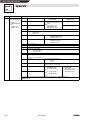
Code
C0068*
Name
Operating
p
g status for:
• 82XX
• 8200 vector
• 93XX
Note
Bit
0-3
4-7
(P2102)
8
9
10
11
12
13
14
82XX
8200 vector
Operating fault (TRIP)
The 10th digit of the LECOM fault number (see C0161 to C0164) is displayed.
Example: TRIP OH = 5 (LECOM no. = 50)
Last communication error
0
=
No fault
1
=
Check sum error
2
=
Protocol frame error
3
=
Reserved
4
=
Invalid code number
5
=
Invalid variable
6
=
No access permission
7
=
Telegram processing interrupted by a new telegram
15 =
General fault
Ctrl. enable
0 = no controller enable
1
=
Controller enable
Qmin (fd
fdQmin)
FREE; fig C0150.Bit 5
fdQmin)
0
=
Qmin not active
Default setting: Qmin (fd
0
=
Qmin not active
1
=
Qmin active
1
=
Qmin active
Direction of rotation
Reserved
0
=
CW rotation
1
=
CCW rotation
IMP (pulse inhibit)
FREE; display of C0150 bit 1
0 = Pulses to power stages inhibi- Default setting: IMP (Pulse inhibit)
ted
0 = Pulses to power stages inhibited
1 = Pulses for power stages ena1 = Pulses for power stages enabled
bled
$
$
QSP (quick stop)
0
=
QSP not active
1
=
QSP active
Imax (current limit reached)
0
=
Current limit not reached
1
=
Current limit reached
fd = fdset (Act. frequency = Frequency setpoint)
fdset
0
=
fd
1
=
fd
fdset
15
93XX
Reserved
FREE; display of C0150 bit 2
Default setting: Imax (Current limit reached)
0
=
Current limit not reached
1
=
Current limit reached
FREE; display of C0150 bit 4
RFG on = RFG off
(Ramp-function generator input = ramp-function generator output)
0
=
HLG on < > HLG off
1
=
RFG on = RFG off
TRIP (fault)
0
=
No error
1
=
Fault occurred
LECOM format: VH
C0125*
LECOM baud rate
(P82XX)
(P93XX)
0
1
2
3
4
9600
4800
2400
1200
19200
Baud (Factory setting)
Baud
Baud
Baud
Baud
Transmission rate for LECOM-A/B/LI in bit/s (= baud).
LECOM format: VD
C0127
Selection Setpoint
selection
0
1
Absolute setpoint selection
Normalized setpoint selection
(P821X, P822X, P824X)
LECOM format: VD
(P2102)
8-4
BA2102EN
Show/Hide Bookmarks
Appendix
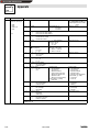
Code
C0135*
Name
Controller control word
(
(parameter
channel)
h
l) ffor:
• 820X
• 821X
• 8200 vector
• 822X
(P2102)
Note
Bit
0
4
JOG1, JOG2, JOG3
0
=
C0046 active
1
=
JOG1 (C0037) active
2
=
JOG2 (C0038) active
3
=
JOG3 (C0039) active
JOG1, JOG2, JOG3
CW/CCW (CW rotation/CCW rotation)
0
=
CW rotation
1
=
CCW rotation
QSP (quick stop)
0
=
QSP not active
1
=
QSP active
Reserved
5
Reserved
6
Reserved
7
Reserved
8
9
Reserved
Ctrl. inhibit (controller inhibit)
0
=
No controller inhibit
1
=
Controller inhibit
Reserved
Reserved
1
2
3
10
11
12
13
14
15
820X
821X, 8200 vector, 822X
RFG stop (stop of the ramp function
generator)
0
=
RFG stop not active
1
=
RFG stop active
RFG zero (deceleration along the Tif
ramp C0013)
0
=
RFG zero not active
1
=
RFG zero active
UP function for motor potentiometer
0
=
UP not active
1
=
UP active
DOWN function for motor potentiometer
0
=
DOWN not active
1
=
DOWN active
TRIP reset
0 1
Edge from 0 to 1 causes TRIP reset
A
PAR (parameter set changeover)
1 (= parameter set 2)
0
0 (= parameter set 1)
1
Reserved
DC brake (DC injection brake)
0
=
DCB not active
1
=
DCB active
A
A
Reserved
The control word controls the controller. It compresses and summarizes control commands in bit commands.
LECOM format: VH
BA2102EN
8-5
Show/Hide Bookmarks
Appendix
Code
C0135*
Name
Controller control word
(p
(parameter channel)) for:
• 93XX general
• 93XX default settingg
for
– C0005 = 1xx1
– C0005 = 4xx1
(P2102)
Note
Bit
General structure
0
FREE 0 (free access)
1
FREE 1 (free access)
2
3
4
FREE 2 (free access)
QSP (quick stop)
0
=
QSP not active
1
=
QSP active
(free access)
5
(free access)
6
7
8
9
12
FREE 6 (free access)
FREE 7 (free access)
Reserved
Ctrl. inhibit (controller inhibit)
0
=
No controller inhibit
1
=
Controller inhibit
Reserved
TRIP reset
0 1
Edge from 0 to 1 causes TRIP reset
(free access)
13
(free access)
14
(free access)
15
(free access)
10
11
1xx1
Speed control
JOG1, JOG2, JOG3
0 = C0141 (speed setpoint in % of
nmax) active
1 = JOG1 (C0039.1) active
2 = JOG2 (C0039.2) active
3 = JOG3 (C0039.3) active
4xx1
Torque control
FREE 0 (free access)
FREE 1 (free access)
NSET-RFG-STOP (stop of the ramp function generator)
0
=
NSET-RFG-STOP not active
1
=
NSET-RFG-STOP active
NSET-FRG-0 (deceleration at the Tif ramp C0013)
0
=
NSET-RFG-O not active
1
=
NSET-RFG-O active
A
PAR*1 (parameter set changeover)
0
=
PS 2/4
1
=
PS 1/3)
PAR-SET
Activate parameter set changeover
Ti1, Ti2, Ti3
0 = C0012/C0013 active
1 = Ti1, (C0102.1/C0103.1)
active
2 = Ti2, (C0102.1/C0103.1)
active
3 = Ti3, (C0102.1/C0103.1)
active
JOG1, JOG2, JOG3
0 = No active JOG
1 = JOG1 (C0039.1) active
2 = JOG2 (C0039.2) active
3 = JOG3 (C0039.3) active
The control word controls the controller. It includes the control commands in a compressed bit format.
LECOM format: VH
8-6
BA2102EN
Show/Hide Bookmarks
Appendix
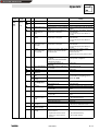
Code
C0135*
Name
Controller control word
(p
(parameter channel)) for:
• 93XX default setting
for
– C0005 = 55xx1
1
– C0005 = 6xx1
– C0005 = 7xx1
(P2102)
Note
Bit
0
1
2
3
4
5
6
7
8
9
10
11
12
13
14
5xx1
Digital frequency master
JOG1, JOG2, JOG3
0 = C0141 (speed setpoint in % of
nmax) active
1 = JOG1 (C0039.1) active
2 = JOG2 (C0039.2) active
3 = JOG3 (C0039.3) active
6xx1
LF slave bus
7xx1
LF slave cascade
FREE 0 (free access)
FREE 1 (free access)
FREE 2 (free access)
QSP (quick stop)
0
=
QSP not active
1
=
QSP active
NSET-RFG-STOP (stop of the ramp function generator)
0
=
NSET-RFG-STOP not active
1
=
NSET-RFG-STOP active
NSET-FRG-0 (deceleration at the Tif ramp C0013)
0
=
NSET-RFG-O not active
1
=
NSET-RFG-O active
FREE 6 (free access)
FREE 7 (free access)
Reserved
Ctrl. inhibit (controller inhibit)
0
=
No controller inhibit
1
=
Controller inhibit
Reserved
TRIP reset
0 1
Edge from 0 to 1 causes TRIP reset
PAR*1 (parameter set changeover)
0
=
PS 2/4
1
=
PS 1/3)
PAR-SET
Activate parameter set changeover
A
REF-ON
Start homing function
15
Ti1
FREE 15 (free access)
0 = C0012/C0013 active
1 = Ti1 (C0102.1/C0103.1)
active
The control word controls the controller. It includes the control commands in a compressed bit format.
LECOM format: VH
C0141
Setpoint
Appropriately
selected
Configuration
Signal configuration
Signal
1xx1
(Speed control)
NSET-N
4xx1
(Torque control)
MCTRL-M-ADD
5xx1
(Master frequency)
NSET-N
6xx1
(Master frequency - slave bus)
NSET-N
7xx1
(Master frequency - slave cascade) NSET-N
BA2102EN
Meaning
Speed setpoint in % of nmax
Torque setpoint in %
Speed setpoint in % of nmax
Speed setpoint in % of nmax
Speed setpoint in % of nmax
8-7
Show/Hide Bookmarks
Appendix
Code
C0150*
Name
Controller status word
(parameter channel) for:
•
•
•
•
820X
821X
8200 vector
822X
Bit
Note
821X, 822X
820X
0
Reserved
1
IMP (pulse inhibit)
0
=
Pulses for power stage enabled
1
=
Pulses for power stage inhibited
2
Imax (current limit reached)
0
=
Current limit not reached
1
=
Current limit reached
Reserved
fd
fdset (Act. frequency =
Frequency setpoint)
0 = fd < > fdset
1 = fd = fdset
fd
fdset (Act. frequency =
RFG on = RFG off
Frequency setpoint)
(RFG input = RFG output)
0 = RFG in < > RFG out
0
=
fd < > fdset
1 = RFG on = RFG off
1
=
fd = fdset
FREE 2 (free access)
Qmin (fd
0
=
1
=
FREE 5 (free access)
(P2102)
3
4
5
Actual parameter set
0
=
PS 1 active
1
=
PS 2 active
$ fdQmin)
fd = 0 (act. frequency = 0)
0
=
fd < > 0
1
=
fd = 0
7
Ctrl. inhibit (controller inhibit)
0
=
No controller inhibit
1
=
Controller inhibit
!controller status
0
=
No error
1
=
Error
12
13
14
FREE 0 (free access)
FREE 3 (free access)
FREE 4 (free access)
Qmin not active
Qmin active
6
8 - 11
!controller status
0 = Unit initialisation
1 = Autostart lock
3 = Operation inhibited
4 = Flying-restart circuit active
5 = DC injection braking active
6 = Operation enable
7 = Message active (dynamically
set pulse inhibit, e.g. at OU)
8 = Fault active
Overtemperature warning ( Jmax - 10 °C)
0
=
No controller inhibit
1
=
Controller inhibit
UGmax (DC-bus overvoltage)
0
=
No overvoltage
1
=
Overvoltage
!controller status
0 = Unit initialisation
1 = Autostart lock
3 = Operation inhibited
6 = Operation enable
7 = Message active (dynamically
set pulse inhibit, e.g. at OU)
8 = Fault active
9 = Power off
Direction of rotation
0
=
CW rotation
1
=
CCW rotation
FREE 14 (free access)
15
Ready for operation (no error, overvoltage or undervoltage)
0
=
Not ready for operation
1
=
Ready for operation
The status word contains the most important status information in a compressed form.
LECOM format: VH
8-8
8200 vector
Free configuration via C0417 (see
Operating Instructions for 8200
vector)
BA2102EN
Warning
0 = No warning
1 = Warning
Message
0 = No message
1 = Message
FREE 15 (free access)
Show/Hide Bookmarks
Appendix
Code
C0150*
Name
Controller status word
(p
(parameter channel)) for:
• 93XX general
• 93XX default setting
for
– C0005 = 1xx1
– C0005 = 4xx1
Note
Bit
General structure
1xx1
Speed control
0
(free access)
1
IMP (pulse inhibit)
0
=
Pulses for power stage enabled
1
=
Pulses for power stage inhibited
2
(free access)
3
FREE 3
(free access)
4
(free access)
5
(free access)
6
fd = 0 (act. frequency = 0)
0
=
fd < > 0
1
=
fd = 0
7
Ctrl. inhibit (controller inhibit)
0
=
No controller inhibit
1
=
Controller inhibit
!controller status
0
=
Unit initialisation
1
=
Switch-on inhibit
3
=
Operation inhibited
6
=
Operation enable
7
=
Message active
8
=
Active fault
9
=
Power off
Warning
0
=
No warning
1
=
Warning
Message
0
=
No warning
1
=
Warning
FREE 14 (free access)
(free access)
(P2102)
8 - 11
12
13
14
15
4xx1
Torque control
Actual parameter set
0
=
PS 2/4 active
1
=
PS 1/3 active
Imax (current limit reached)
0
=
Current limit not reached
1
=
Current limit reached
RFG on = RFG off
(RFG input = RFG output)
0 = RFG in < > RFG out
1 = RFG on = RFG off
Qmin (fd
fdQmin)
0
=
Qmin not active
1
=
Qmin active
$
n = 0 (actual speed value = 0)
0
=
n< > 0
1
=
n= 0
Ready for operation (no error, overvoltage or undervoltage)
0
=
Not ready for operation
1
=
Ready for operation
The status word contains the most important status information in compressed form.
On the following pages you will find the assignment of the freely combineable bits for the predefined signal configuration of
the controller.
LECOM format: VH
BA2102EN
8-9
Show/Hide Bookmarks
Appendix
Code
C0150*
Name
Controller status word
(p
(parameter channel)) for:
• 93XX default setting
for
– C0005 = 5xx1
– C0005 = 6xx1
– C0005 = 7xx1
Note
Bit
5xx1
Digital frequency master
0
Actual parameter set
0
=
PS 2/4 active
1
=
PS 1/3 active
1
IMP (pulse inhibit)
0
=
Pulses for power stage enabled
1
=
Pulses for power stage inhibited
2
REF-OK
0
=
Homing function not ok
1
=
Homing function ok
Mmax (torque limit reached)
NOT1-OUT
0 = torque limit not reached
0
=
1 = torque limit reached
1
=
RFG on = RFG off
(RFG input = RFG output)
0
=
RFG in < > RFG out
1
=
RFG on = RFG off
REF-BUSY
0
=
Homing function not active
1
=
Homing function active
(P2102)
3
4
5
6
6xx1
LF slave bus
7xx1
LF slave cascade
torque limit reached
torque limit not reached
n = 0 (actual speed value = 0)
0
=
n< > 0
1
=
n= 0
7
Ctrl. inhibit (controller inhibit)
0
=
No controller inhibit
1
=
Controller inhibit
8 - 11 !controller status
0
=
Unit initialisation
1
=
Switch-on inhibit
3
=
Operation inhibited
6
=
Operation enable
7
=
Message active
8
=
Active fault
9
=
Power off
12
Warning
0
=
No warning
1
=
Warning
13
Message
0
=
No warning
1
=
Warning
14
FREE 14 (free access)
15
Ready for operation (no error, overvoltage or undervoltage)
0
=
Not ready for operation
1
=
Ready for operation
The status word contains the most important status information in compressed form.
On the following pages you will find the assignment of the freely combineable bits for the predefined signal configuration of
the controller.
LECOM format: VH
8-10
BA2102EN
Show/Hide Bookmarks
Appendix
Code
C0161*
C0162*
C0163*
C0164*
Name
Fault
memory
Keypad
PC
Error
Cause
Remedy
1)
0
No error
-
-
EE
71
System
y
error
Shield control cables
EF
61
Communication error to
AIF
Strong interference on control cables
Ground or earth loops in the wiring
Faulty transmission of control commands
via AIF
EF
62
Communication error to
CAN-IN1 with sync
control
CAN-IN1-object receives faulty data or
communication is interrupted
Plug-in connection - bus module
Check FIF
Check transmitter
Increase monitoring time under C0357/1 if
necessary
EF
63
Communication error to
CAN-IN2
CAN-IN2-object receives faulty data or
communication is interrupted
Plug-in connection - bus module
Check FIF
Check transmitter
Increase monitoring time under C0357/2 if
necessary
EF
64
Communication error to
CAN-IN1 with event or
time control
CAN-IN1-object receives faulty data or
communication is interrupted
Plug-in connection - bus module
Check FIF
Check transmitter
Increase monitoring time under C0357/3 if
necessary
EF
65
BUS-OFF
(many communication
errors occurred)
Controller has received too many incorrect Check whether bus terminator available
telegrams via the system bus and has
Shield control of the cables
been disconnected
Check PE connection
Check bus load, if necessary, reduce the baud
rate
EF
66
CAN Time-Out
For remote parameter setting via system
bus (C0370):
Slave does not answer. Communication
monitoring time exceeded.
For operation with module in FIF:
Internal fault
A digital signal assigned to TRIP set has
been activated
(P82XX)
((
91
External fault (TRIP-Set)
Insert the communication module into the hand
terminal
Ø
Ø
Ø
Check system bus wiring
Check system bus configuration
Contact Lenze
Check external encoder
+
105 Internal fault
J
140 Faulty parameter
identification
Motor not connected
Connect motor
32
Failure of one/several motor phase(s)
Contact Lenze
182 Fault in motor phase
(warning)
103 DC-bus undervoltage
0 (only message witho
withoutt
TRIP)
Motor current too low
Check motor cables,check Vmin boost, connect
p
g ppower or
the motor with the corresponding
adapt
d t it under
d C0599
C0599.
Mains voltage too low
Check mains voltage
DC-bus voltage too low
Check supply cable
2&
11
short-circuit
short-circuit
Excessive capacitive charging current of
the motor cable
Find reason for short-circuit; check motor cable
Use shorter motor cables with lower charging
current
2&
12
Earth fault
Grounded motor phase
Excessive capacitive charging current of
the motor cable
Check motor, check motor cable
Use shorter motor cables with lower charging
current
2&
13
Overload inverter during
acceleration or short
circuit
i it
Acceleration time too short (C0012)
• Increase acceleration time
• Check drive dimensioning
Controller overload in
stationary operation
Motor overload (I2 x t
overload))
Frequent and long overload
/3
/8
2&
14
2&
15
2&
16
Fault in motor phase
(TRIP)
Defective motor cable
Interturn fault in the motor
Overload controller during Deceleration time set too short (C0013)
deceleration
Check wiring
Check motor
• Increase deceleration time
• Check size of external brake resistor
Check drive dimensioning
Motor is thermally overloaded, for
instance, because of
• impermissible continuous current
• frequent or too long acceleration
• Check drive dimensioning
• Check setting of C0120
processes
BA2102EN
8-11
Show/Hide Bookmarks
Appendix
Code
Name
Keypad
PC
Error
Cause
50
2+
Heat sink temperature
Ambient temperature Tamb > + 60 C
exceeds the value
entered for the controller
Heat sink very dirty
Impermissibly high currents or too
frequent and too long acceleration
2+
2+
28
8-12
53
PTC monitoring (TRIP)
• Allow controller to cool and ensure better
ventilation
• Check ambient temperature
Clean heat sink
• Check drive selection
• Check load, if necessary, replace defective
bearings
Motor too hot because of excessive
current, or acceleration is too frequent
and too long
203 PTC monitoring (warning) PTC not connected
Check drive dimensioning
102 DC-bus overvoltage
g
0 (only message without
TRIP)
Mains voltage too high
Braking operation
Check voltage supply
• Prolong deceleration times.
• For operation with brake transistor:
– Check the selection and connection of the
brake resistor
– Increase the deceleration times
Earth leakage on the motor side
Check motor cable and motor for earth fault
(disconnect motor from inverter)
It is absolutely necessary to repeat the data
g before
transfer or load the Lenze setting
enabling
bli th
the controller.
t ll
Connect PTC or switch off monitoring
3
75
Faulty parameter transfer All parameter sets are defective
when using the keypad
3 72
Wrong PAR1 transfer
when using the keypad.
PAR1 is defective.
3 73
Wrong PAR2 transfer
when using the keypad.
PAR2 is defective.
3 77
Wrong PAR3 transfer
when using the keypad.
PAR3 is defective
3 78
Wrong PAR4 transfer
when using the keypad.
PAR4 is defective
3S
81
Time error during
parameter set transfer
6S
76
Faulty auto-TRIP reset
Data flow from keypad or PC interrupted,
e. g. keypad was disconnected during
transmission
More than 8 fault messages in 10 minutes Depends on the fault message
85
Open circuit at analog
input
R
1)
Remedy
1)
Current at analog input < 4 mA
Close circuit at analog input
LECOM fault numbers
BA2102EN
Show/Hide Bookmarks
Appendix
Code
C0067
C0161
C0168*
[1...8]
C0248*
Name
Fault memory
(P93XX)
LECOM input
selection
(P2102)
Note
Fault abbreviations
LECOM fault numbers
TRIP
Warning
Message
--0
OC1
11
OC2
12
OC5
15
OU
1020
LU
1030
LP1
OH
50
OH3
53
OH4
2054
OH7
2057
OH8
58
2058
CE0
61
2061
CE1
62
2062
CE2
63
2063
CE3
64
2064
U15
70
CCr
71
Pr0
75
Pr1
72
Pr2
73
Pr3
77
Pr4
78
PEr
74
PI
79
Sd2
82
2082
Sd3
83
2083
Sd6
86
2086
EEr
91
2091
1091
P03
153
2153
P13
163
NMAX
200
H05
105
H07
107
H10
110
H11
111
The individual faults are described in the Operating Instructions of the controller.
LECOM format: VD
0
0 to 255
The parameter LECOM input selection ensures the compatibility with previous master-system drivers according to the LECOM-A/B
specification V1.0. This code is only fully used with 93XX, since this series uses the so-called array parameters, i. e. a code
consists of several parameters (e.g. C0039 = JOG with 15 values). Code C0248 determines the array element to be accessed. The
functionality of the input selection is simulated (before e.g. C0038).
This input is valid for all LECOM accesses; i.e. the access of a standard parameter with a LECOM input selection that is not 0
results in a fault because the addressed value does not exist.
The array element can be directly addressed via a LECOM-A/B driver as from specification V2.0. This parameter should therefore
not be used any longer.
C0248 is included in every LECOM code bank (see C0249).
The parameter value is always set to 0 when switching on.
LECOM format: VD
BA2102EN
8-13
Show/Hide Bookmarks
Appendix
Code
Name
C0249*
LECOM code bank
Note
Code bank
Code number
0
1
2
3
4
5
6
7
8
9
10
11
12
13
14
15
(P2102)
0
250
500
750
1000
1250
1500
1750
2000
2250
2500
2750
3000
3250
3500
3750
to
to
to
to
to
to
to
to
to
to
to
to
to
to
to
to
255 (Factory setting)
505
755
1005
1255
1505
1755
2005
2255
2505
2755
3005
3255
3505
3755
4005
The LECOM code bank ensures the compatibility with the master-system drivers according to the LECOM-A/B specification V1.0.
The maximum code number is 255. With the code bank, an offset of 250 is added to the code number.
The code bank addressing is not effective with extended code addressing (LECOM-A/B specification).
The parameter value is always set to 0 when switching on.
LECOM format: VD
C1810*
SW labelling
33S2102I_xy000
(P2102)
Software labelling of the 2102IB fieldbus modules
x = main SW version y = SW subversion
LECOM format: VS
C1811*
C1920
SW generation
Software generation of the 2102IB fieldbus module
(P2102)
LECOM format: VS
Start status
0
1
QSP
Controller inhibit
(P2102)
LECOM format: VD
C1922
Monitoring selection
code
0
1
2
Not active
Controller inhibit
QSP (quick stop)
(P2102)
LECOM format: VD
C1921
C1923
C1962
Shortened response
time
0
1
Not active
active
(P2102)
LECOM format: VD
Monitoring time
50 to 65535ms
(P2102)
LECOM format: VD
Extended code No.
See fault table
The following list shows the fault numbers which can be read under C1962:
Fault no.
0
1
2
3
4
5
6
7
8-14
Meaning
No fault
Invalid service designation
Invalid call recognition
Invalid data type
Invalid subcode number
Invalid code number
Invalid general parameter
Access error: operating status, e.g. controller inhibit
Classification
Internal fault
Internal fault
Application error in the host
Application error in the host
Application error in the host
Application error in the host
Access error
BA2102EN
Show/Hide Bookmarks
Appendix
Fault no.
8
9
10
11
12
13
14
17
32
33
34
35
36
37
38
208
209
210
211
212
213
214
Meaning
Access error: because operating mode C0001
Access error: parameter only readable
Access error: general
Data block too long
Collision with other parameter values
Leave value range
General limit value exceeding
General internal fault
General
Time limit exceeded
Frame error
Parity error
Overflow
Handshake
Block memory overflow
Frame error
Overflow error
Check-sum fault in the 2102IB fieldbus module detected
Telegram interruption
Invalid data
Invalid service
Parity error
Classification
Access error
Access error
Access error
Limit value exceeded
Limit value exceeded
Limit value exceeded
Limit value exceeded
Internal fault
Communication fault 2102IB < -> controller
Communication fault 2102IB < -> controller
Communication fault 2102IB < -> controller
Communication fault 2102IB < -> controller
Communication fault 2102IB < -> controller
Communication fault 2102IB < -> controller
Communication fault 2102IB < -> controller
Communication fault controller < -> 2102IB
Communication fault controller < -> 2102IB
Communication fault controller < -> 2102IB
Communication fault controller < -> 2102IB
Communication fault controller < -> 2102IB
Communication fault controller < -> 2102IB
Communication fault controller < -> 2102IB
BA2102EN
8-15
Show/Hide Bookmarks
Appendix
8.3
LECOM-A/ B protocol
The LECOM-A/B protocol is used to exchange data between Lenze controllers and a host. The
LECOM-A/B protocol is based on DIN 66019, ISO 1745 and ANSI X3.28 (category 2.5 and A2, A4).
These standards are similar to each other and describe the control mode of a transmission section
of a transmission system.
The host, which is the master, can communicate with a slave (Lenze controller) in three modes:
• RECEIVE (see page 8-21)
• SEND (see page 8-23)
• BROADCAST/MULTICAST (see page 8-24)
8.3.1
General
The controllers communicate by means of the ASCII code:
0
1
2
3
4
5
6
7
0
NUL
DLE
‘’
‘0’
‘@’
‘P’
‘‘’
‘p’
1
SOH
DC1
‘!’
‘1’
‘A’
‘Q’
‘a’
‘q’
2
STX
DC2
‘”’
‘2’
‘B’
‘R’
‘b’
‘r’
3
ETX
DC3
‘#’
‘3’
‘C’
‘S’
‘c’
‘s’
4
EOT
DC4
‘$’
‘4’
‘D’
‘T’
‘d’
‘t’
5
ENQ
NAK
‘%’
‘5’
‘E’
‘U’
‘e’
‘u’
6
ACK
SYN
‘&’
‘6’
‘F’
‘V’
‘f’
‘v’
7
BEL
ETB
‘’’
‘7’
‘G’
‘W’
‘g’
‘w’
8
BS
CAN
‘(’
‘8’
‘H’
‘X’
‘h’
‘x’
9
HT
EM
‘)’
‘9’
‘I’
‘Y’
‘i’
‘y’
O
LF
SUB
‘*’
‘:’
‘J’
‘Z’
‘j’
‘z’
B
VT
ESC
‘+’
‘;’
‘K’
‘[’
‘k’
‘{’
C
jFF
FS
‘,’
‘<’
‘L’
‘\’
‘l’
‘|’
D
CR
GS
‘-’
‘=’
‘M’
‘]’
‘m’
‘}’
I
SO
RS
‘.’
‘>’
‘N’
‘^ ’
‘n’
‘~’
F
SI
US
‘/’
‘?’
‘O’
‘_’
‘o’
Example:
”EOT”
Character ”1”
= 02hex = 2dec
= 31hex = 49dec
Code number (C1, C2)
Standard addressing
The meaning of the code numbers and the assigned parameters can be obtained from the code
table (see chapter 8.2). When transmitting data, the code number are coded as follows:
The following calculation determines the two ASCII digits from the code number (value range: 0 ¡
6229) (value range: 48dec ¡ 127dec ):
C1 =
INTEGER((REMAINDER(code number/790))/10)+48dec
C2 =
REMAINDER(REMAINDER(code number/790)/10) +
INTEGER(code number/790) x 10 + 48dec
The INTEGER is the digit before the decimal point, the REMAINDER is an integer.
Example:
13/5 = 2 remainder 3
INTEGER(13/5) = 2
REMAINDER(13/5) = 3
Example:
Convert code number 1002 in ASCII code C1 and C2:
8-16
C1 ASCII =
INTEGER((REMAINDER(1002/790))/10) + 48 =
INTEGER(212/10) + 48 =
21 + 48 = 69 = 45hex = ”E” ASCII
C2ASCII =
REMAINDER(REMAINDER(1002/790)/10) +
INTEGER(1002/790) x 10 + 48 =
REMAINDER(212/10) + 1 x 10 + 48 =
2 + 10 + 48 = 60 = 3Chex = ”<” ASCII
BA2102EN
Show/Hide Bookmarks
Appendix
The code number C1002 is converted into the ASCII string ”E<”, if they are transmitted to the
controller by a host.
Addressing via code bank
With previous LECOM-A/B drivers, only code numbers in the range from 0 to 255 could have been
addressed, since these drivers used only one byte as code number. To achieve the addressing of
the wider code-number range with these drivers, use the code banking.The code-number range 0
¡ 255 is displayed as a window over the whole code-number range. This is controlled via the code
C0249 (code bank). Code C0249 can always be accessed via number 249, independent of the
currently set code bank.
Assignment:
Code bank
0
1
2
3
4
5
6
7
Code offset
0
250
500
750
1000
1250
1500
1750
Code-number range
0 ¡ 255
250 ¡ 505
500 ¡ 755
750 ¡ 1005
1000 ¡ 1255
1250 ¡ 1505
1500 ¡ 1755
1750 ¡ 2005
Note:
Code banking is only active when the standard addressing is being used. If the selected code
numbers are higher than 255, the code-number range increases correspondingly. Only the
corresponding code-number offset is selected by means of the code bank.
Example:
Set the code bank INTEGER (1002/250) =4 in C0249 to address the code number 1002. C1002 is
then accessed via the code number C02.
Addressing via input selection
Simple LECOM-A/B drivers, which only use the standard addressing, cannot address subcodes.
The input selection C0248 has been developed to offer the possibility of addressing the subcodes.
When using the standard addressing, the value entered in C0248 is always considered as the
subcode. The code C0248 can always be accessed via number 248, independent of the currently
set code bank and the subcode used.
Example:
Enter value 1 in C0248 to address the JOG value 1 in subcode 1. Now subelement 1 is always
addressed when accessing C39.
Tip!
After a subelement has been accessed through C0248, C0248 should be reset to 0 to avoid the
addressing of a subelement ”by accident” when accessing a code.
BA2102EN
8-17
Show/Hide Bookmarks
Appendix
Extended addressing
Another possibility is the direct addressing of parameters by means of expanded addressing.
!
CH1
CH2
CH3
CH4
SC1
SC2
The abbreviations have the following meanings:
The ASCII character ”!” = 21hex = 33dec shows
that the expanded addressing is
used.
Code number in hexadecimal code:
each character corresponds to a nibble of the
code numbers (CH1 is the highest,
CH4 is the lowest nibble).
Subcode number in hexadecimal code:
Each character corresponds to a nibble of the
code number word (SC1 is the highestand SC2 the lowest nibble).
!
CH1 to CH4
SC1, SC2
The following characters can be displayed in the ASCII code:
ASCII
0
1
2
3
4
5
6
7
8
9
O
B
C
D
I
F
dec
48
49
50
51
52
53
54
55
56
57
65
66
67
68
69
70
hex
30
31
32
33
34
35
36
37
38
39
41
42
43
44
45
46
A code number range from 0 to 65535 can be addressed by means of these characters. A maximum
of 255 subelements (field elements) can be accessed via one subcode number of each code.
Example:
1002 = ”!03EA00”
Parameter value (V1 to Vn)
Parameter values can be transmitted in four different formats with the following structures:
• ASCII decimal format (VD)
-
VK1
VK2
VK3
VK4
VK5
VK6
.
NK1
NK2
NK3
NK4
• ASCII hexadecimal format (VH)
H
VH1
VH2
VH3
VH4
VH5
VH6
VH7
VH8
• String format (VS)
S
VS1
VS2
VS3
VS4
VS5
VS6
...
VS240
VO4
VO5
VO6
...
VO240
• Octet string format for data blocks (VO)
O
8-18
VO1
VO2
VO3
BA2102EN
Show/Hide Bookmarks
Appendix
The abbreviations have the following meanings:
VK1 to VK6
Integers
.
Decimal point (if required)
NK1 to NK4
Decimal codes (if required)
”H” (48hex)
Character [H], transfer of parameter values
in the ASCII hexadecimal format
VH1 to VH8
1 to 8 hexadecimal characters each
[0 to 9; A to F]
”S” (53hex)
Character [S], transfer of parameter values
in the string format
VS1 to VS240 1 to 12 visible ASCII characters each
(no control characters)
”O” (4Fhex)
Character [O], transfer of parameter values
in the octett string format
VO1 to VO240 Data block in hexadecimal code;
Each character corresponds to a nibble of the
data block
Parameter value in the ASCII decimal format (VD)
The ASCII decimal format (VD) is most often used. The values consist of the following:
1 leading negative sign (if required)
6 digits before the decimal point (VK1 to VK6)
1 decimal point
(if required)
4 digits after the decimal point (NK1 to NK4) (if required)
Values from -214748.3648 to 214748.3647 can be displayed.
Tip!
In the ASCII decimal format (VD), the decimal point must not be transmitted if the value does not
have digits after the decimal point.
Parameter value in ASCII hexadecimal format (VH)
The LECOM-A/B protocol supports the transmission of hexadecimal parameter values with a length
of:
• 2 characters (byte value)
• 4 characters (wort/integer value)
• 8 characters (double word/long integer)
In the ASCII hexadecimal format, VH1 is the most significant and VH8 the least significant
hexadecimal character.
Parameter value in the string format (VS)
By means of the string format (VS) of the protocol it is possible to transmit strings with max. 20
characters in both directions.
The Lenze controller can only send the string parameters (e. g. C200).
Parameter values in the octett string format (VO)
The LECOM-A/B protocol includes the octett string format (VO) with which it is possible to transfer
data blocks.
The character sequence corresponds to the filing in the memory (ascending order), i. e. the
character transmitted first is the data block nibble with the lowest address. The data structure of the
data block corresponds to the Intel-memory format with the following definition:
BYTE:
1st high nibble
2nd low nibble
WORD:
1st high BYTE
2nd low BYTE
DWORD:
1st high WORD
2nd low WORD
BA2102EN
8-19
Show/Hide Bookmarks
Appendix
Controller address (AD1, AD2)
One or more bus devices (slaves) can be selected by means of the controller address which is 2
bytes (AD1, AD2) long. The LECOM-A/B protocol supports the broadcast telegrams, i.e. a telegram
is sent to a group or all other bus devices. For this, controller addresses are reserved (see
BROADCAST, page 8-24). Controller addresses have the following structure:
AD1
AD2
The abbreviations have the following meanings:
AD1
ASCII ten-digit of the slave address (0 ¡ 9; 30 ¡ 39hex)
AD2
ASCII one-digit of the slave address (0 ¡ 9; 30 ¡ 39hex)
Block-check character (BCC)
The block-check character (BCC) is used to store the transmitted data and is generated according
to DIN 66219 (chapter 3).
Because of the program, the block-check character is generated by a XOR link from the following
digits of the SEND telegram:
• it starts with the character directly after the STX control character
• it ends directly after the ETX control character
– BCC can accept the value 00 ¡ FFhex.
EOT
AD1
AD2
STX
C1
C2
V1
...
Vn
ETX
BCC
< ——————— BCC ———————>
or with the expanded addressing:
STX
”!”
CH1
CH2
...
SC2
ETX
BCC
< —————————— BCC —————————>
Telegram response
The Lenze controller must return an acknowledgement to the host. The only exception is the
broadcast telegram. This telegram does not require an acknowledgement.
The Lenze controller sends two types of acknowledgements:
• Positive acknowledgement (ACK = 06hex), if:
– no faults occur during the block storage (longitudinal and lateral parity)
– a valid command (variable address) has been recognized
– the variable value is within the permissible range
– the variable value could have been changed
• negative acknowledgement (NAK = 15hex), if:
– one of the above listed conditions cannot be met.
• No acknowledgement, if:
– a broadcast telegram is send
– the controller address is not correct
8-20
BA2102EN
Show/Hide Bookmarks
Appendix
8.3.2
RECEIVE
The command RECEIVE is to request parameter values of the Lenze controllers. The code numbers
of the requested parameter are transmitted via the RECEIVE telegram using the following structure:
EOT
AD1
AD2
C1
C2
ENQ
The abbreviations have the following meanings:
EOT (04hex)
AD1, AD2
C1, C2
ENQ (05hex)
End of the (previous) transmission
Logic unit address of the slave to be addressed
Slaves
Code number (two ASCII characters)
or extended addressing
Station request
Structure and meaning of the code numbers (C1, C2) and the controller address (AD1, AD2) are
described in the corresponding paragraphs of the chapter SEND (see page 8-23).
Telegram response
The Lenze controller addressed via a RECEIVE telegram generates one of the following responses:
• The controller could decode the request and is now sending the requested parameter value
to the host.
STX
C1
C2
V1
...
Vn
ETX
BCC
• The controller could decode the request, however, a check-sum fault (parity fault) occurred
during transmission.
STX
C1
C2
?
ETX
BCC
• The controller could not process the request because the requested code number does not
exist.
STX
C1
C2
EOT
The abbreviations have the following meanings:
STX (02hex)
C1, C2
V1 to Vn
ETX (03hex)
BCC
? (3Fhex)
EOT (04hex)
Start of text
Code number (two ASCII characters)
or extended addressing
Parameter value (n ASCII characters)
End of text
Block-check character (00 ¡ FFhex)
ASCII character ”?”
End of the (previous) transmission
Structure and meaning of the block-check character (BCC) are described in the corresponding
paragraph of the chapter SEND (see page 8-20).
BA2102EN
8-21
Show/Hide Bookmarks
Appendix
Examples for a RECEIVE telegram
Example 1
The current speed setpoint (code number C46)is to be read with the bus address 01 at the controller.
The host sends the following RECEIVE telegram
EOT
0
1
4
6
ENQ
The controller can respond in three different ways:
STX
4
6
3
5
.
4
ETX
BCC
Valid request: The current value of the parameter C46 is 35.4 (Hz)
or
STX
4
6
?
ETX
BCC
Invalid request: A check-sum fault (parity fault) occurred during data transmission
or
STX
4
6
EOT
Invalid request: Parameter C46 does not exist in this controller.
Example 2
The current operating status (code number C68) is to be read with the bus address 25 for the
controller.
The operating status is bit-coded and transmitted in the hexadecimal format.
The host sends the following RECEIVE telegram
EOT
2
5
6
8
ENQ
The controller’s response:
STX
6
8
H
0
9
0
0
ETX
BCC
Valid request: The current value of the parameter C68 is ”0900”. This means:
TRIP status
Maximum current
Quick stop
Pulse inhibit status
Display of the direction of rotation
Qmin status
Controller enable
Operating fault
Communication error
8-22
not active
not reached
not active
free
CW rotation
not active
enabled
did not occur
did not occur
BA2102EN
Show/Hide Bookmarks
Appendix
8.3.3
SEND
The command SEND is to transmit data from the master to the slave. The master then sends a
telegram with the following structure:
EOT
AD1
AD2
STX
C1
C2
V1
...
Vn
ETX
BCC
The abbreviations have the following meanings:
EOT (04hex)
AD1, AD2
STX (02hex)
C1, C2
V1 to Vn
ETX (03hex)
BCC
End of the (previous) transmission
Logic unit address of the slave to be addressed
Slaves
Start of text
Code number (two ASCII characters)
Parameter value (n ASCII characters)
End of text
Block-check character (00 ¡ FFhex)
In the text section of the telegram, which is embedded between the control characters STX and ETX,
the code number (C1, C2) and the corresponding parameter value (V1 to Vn) are transmitted to the
slave.
Example for a SEND telegram
The maximum speed (code number C11) is to be set to the value 95.2 Hz via the bus address 34 at
the controller.
The host must send the following SEND telegram:
EOT
3
4
STX
1
1
9
5
.
2
ETX
BCC
The controller can respond with two different acknowledgements:
ACK
The command could not be processed correctly. The current value of the parameter C11 is 95.2 Hz
or
NAK
The request could not been processed correctly. The parameter value was not changed.
BA2102EN
8-23
Show/Hide Bookmarks
Appendix
8.3.4
BROADCAST / MULTICAST
In a bus network, the command BROADCAST is to address all devices or a group of devices
(multicast) at the same time. The structure of the BROADCAST telegram is similar to the structure
of the SEND telegram. The only exception is that it does not return an acknowledgement.
The devices can be selected via their controller addresses. The following controller addresses are
reserved for a BROADCAST telegram:
controller
addresses
(reserved)
controller address of
groups
00
10
20
30
40
50
60
70
80
90
all
11 to 19
21 to 29
31 to 39
41 to 49
51 to 59
61 to 69
71 to 79
81 to 89
91 to 99
ASCII character
AD1
AD2
”0”
”1”
”2”
”3”
”4”
”5”
”6”
”7”
”8”
”9”
”0”
”0”
”0”
”0”
”0”
”0”
”0”
”0”
”0”
”0”
Example for a BROADCAST telegram
All controllers are to be stopped when setting controller enable (code number C40 = 0).
The host send the following BROADCAST telegram:
EOT
0
0
STX
4
0
0
ETX
BCC
The controllers do not return an acknowledgement.
8.3.5
Monitoring of the slave response
The master monitors the selected slave. The slave must return a response within a defined
time.Under the following circumstances the slave does not return a response to the master (time
out):
• The controller address could not be recognized
• A fault (e.g. parity fault) had been detected in one or several characters, including the
character ”ENQ”
• The transmission path is faulty
• A BROADCAST telegram had been sent
• The hardware does not work properly
If the master does not receive a response within a defined period of time, the transmission is tried
again. The number of repetitions is limited.
The monitoring time in the master should be approx. twice as long as the maximum response time.
8.3.6
Transmission faults
After a transmission fault, the master can read C0068 and evaluate the communication error in bit
4¡7. .
8-24
BA2102EN
Show/Hide Bookmarks
Appendix
8.4
List of abbreviations
Abbreviation
ACK
ASCII
Ctrl. enable
Ctrl. inhibit
DCB
EMC
fdmin; fdmax
Imax
IMP
JOG (JOG1, JOG2, JOG3)
LECOM
LECOM-A
LECOM-B
LECOM-LI
LEMOC
NAK
Optical fibre
PAR
PC
PLC
Qmin
QSP
RFG
RS232
RS485
RxD
SW
TRIP
TxD
UGmax
VD
VH
VS
Meaning
Response for positive acknowledgement of the controller
American Standard Code for Information Interchange: 7 bit code with one free parity bit
Controller enable
Controller inhibit
DC-injection brake
Electromagnetic Compatibility
Minimum/maximum field frequency
Current limit
Pulse inhibit
Fixed speed or input for activation of the fixed speed
Lenze communication
Communication medium via RS232 interface and LECOM protocol
Communication medium via RS485 interface and LECOM protocol
Communication medium via optical fibre and LECOM protocol
PC program (for IBM compatible PCs) for drive programming
Response for negative acknowledgement of the controller
Optical fibre
Parameter set changeover
Personal computer
Programmable logic controller, e. g. SIMATIC S5, SIEMENS
Frequency threshold
Quick stop
Ramp-function generator; setpoint integrator
Interface standard
Interface standard
Pin name LED (receive display)
Software
Operation fault
Pin name LED (transmission display)
DC-bus overvoltage
LECOM format
LECOM format
LECOM format
BA2102EN
8-25
Show/Hide Bookmarks
Appendix
8.5
Glossary
Technical term
Baud rate
Broadcast
Code
Code number
Fieldbus
Host
Icon
Interface converter
LEMOC
Meaning
Transmission speed of data in bit/s
Message to all controllers
For input and display (access) of parameter values.
Addressing of variables according to the format „code-subcode“ (Cxxxx-xx). All variables can be accessed via the code names.
For data exchange between superimposed controls and positioning controls.
PC or PLC
Sign or symbol with an unambiguous message.
Additional module to adapt data transmissions via RS232 interface cables to RS485 (and vice versa)
PC program (for IBM compatible PCs) for drive
programming
Multicast
Nibble
Message to certain controller groups
One byte consists of two nibbles:
• LOW nibble (bit 0 to 3)
• HIGH nibble (bit 4 to 7)
LECOM-A/B protocol
The output of the power stage is inhibited because the controller is inhibited, the fault message TRIP is displayed or an overvoltage or
undervoltage is applied.
Protocol
Pulse inhibit
Remaining hazards
Subcode
Table position
8-26
Hazards which cannot be eliminated by design
Defines the table position of a code
Some variables may consist of more than one value. If this is the case, the values are entered subsequently. They are accessed by
means of the same code name via the subcode.
BA2102EN
Show/Hide Bookmarks
Appendix
8.6
Table of keywords
2102IB fieldbus module, Connections, 4-1
C
Cable, Optical fibre, 4-9
Character format, 3-1
A
Code bank, 8-14, 8-17
Accessories, 8-1
for a host, 8-1
Code table, 8-3
Commissioning, 5-1
for optical fibres (LECOM-LI), 8-2
Communication media, 3-1, 3-2
for RS232 (LECOM-A), 8-1
Communication monitoring, 6-4
for RS485 (LECOM-B), 8-2
Communication times, 3-3
Acknowledgement, 8-20
Connection
9-pole SubD female plug, 4-2
Connections of the fieldbus module, 4-1
Plug-in terminal (2-pole), 4-2
Plug-in terminal (4-pole), 4-2
negative, 7-1
positive, 7-1
TRIP reset, 6-5
Control word, 6-2, 8-5, 8-6, 8-7, 8-8, 8-9, 8-10
Addressing
Controller
Application as directed, 1-2
Group formation, 6-3
Labelling, 1-2
Code bank addressing, 8-17
Extended addressing, 8-18
Standard addressing, 8-16
Via input selection, 8-17
Controller address, 5-1, 6-3, 8-3, 8-20
Controller inhibit, 6-2, 6-5, 8-3
Appendix, 8-1
Application as directed, 1-2
Application conditions, 3-1
Current consumption, 3-2
D
Dimensions, 3-2
E
B
Electrical data. See Ratings
Basic insulation, 4-4
Electrical installation, 4-3
Electrical isolation, 4-4
Baud rate, 3-1, 5-1
Extended addressing, 8-18
See Baud rate
BCC, 8-20
F
Fault elimination, 7-1
Block-check character, 8-20
BROADCAST, 8-24
Example, 8-24
Fault memory, 8-11
Fault numbers, 8-14
Frequency setpoint, 6-2, 8-3
BA2102EN
8-27
Show/Hide Bookmarks
Appendix
G
N
Glossary, 8-26
Group addressing, 5-1
Network topology
Group formation, of controllers, 6-3
Line, 4-6
I
Point-to-point, 4-5
Initial switch-on. See Installation
Ring, 4-8
Input selection, 8-13, 8-17
Installation
Electrical, 4-3
Mechanical, 4-3
of optical-fibre cables, 4-9
Wiring to a host, 4-4
Wiring via optical fibre (LECOM-LI), 4-8
Wiring viaRS232 (LECOM-A), 4-5
Wiring viaRS485 (LECOM-B), 4-6
O
Operating mode, 6-2, 8-3
Interface, Reduce response time, 6-4
Interface converter, 8-2
Operating status, 8-4
L
Operator, 2-1
Labelling, Controller, 1-2
LECOM, Protocol, 8-16
Optical fibre
LECOM baud rate. See Baud rate
LECOM code bank. See Code bank
Cable, 4-9
LECOM controller address. See Controller address
Installation of the optical-fibre ring, 4-9
LECOM input selection. See Input selection
LECOM-A/B protocol, 6-3, 8-16
Optical fibre (LECOM-LI), Features, 4-8
Legal regulations, 1-2
Optical fibre/RS232 converter , 8-2
Liability, 1-2
List
Abbreviations, 8-25
Technical term. See Glossary
Optical-fibre cable
Bending radius, 4-9
List of abbreviations, 8-25
Installation of the optical-fibre ring, 4-9
M
Preparation, 4-9
Manufacturer, 1-2
preparation, 4-9
Monitoring of the slave response, 8-24
MULTICAST, 8-24
8-28
Specification, 8-2
BA2102EN
Show/Hide Bookmarks
Appendix
P
S
Packing list, 1-1
Safety information, 2-1
Layout, 2-2
Other notes, 2-2
Warning of damage to material, 2-2
Warning of damage to persons, 2-2
Parameter sets, 6-1
Parameter setting, 6-1
Special features, 820X, 6-5
Parameter value, 8-18
in the ASCII decimal format, 8-19
in the ASCII hexadecimal format, 8-19
in the octett string format, 8-19
in the string format, 8-19
Parameters
Control word (C0135), 6-2
Controller inhibit (C040), 6-2
Frequency setpoint (C0046), 6-2
Meaning of individual, 6-2
Operating mode (C0001), 6-2
Unit address (C0009), 6-3
parameters, Name, 8-3
PC system cable, 8-1
Personnel, qualified, 2-1
Plug-in terminal for external supply, Connections, 4-2
Plug-in terminal for LECOM-B, Connections, 4-2
Processing time, 3-4
Protocol, 8-16
See LECOM-A/B protocol
Code numbers, 8-16
Q
SEND, 8-23
Example, 8-23
Slave response, 8-24
Software driver, 3-3
Special features, Parameter setting, 820X, 6-5
Standard addressing, 8-16
SubD male plug (9-pole), Connections, 4-2
Supply voltage
External, 3-2, 4-3
Internal, 4-3
T
Technical data, 3-1
Dimensions, 3-2
General data/Application conditions, 3-1
Module features, 3-1
Ratings, 3-2
Telegram response, 8-20
Telegram time, 3-3
Transmission faults, 8-24
TRIP reset, 6-5, 8-3
Troubleshooting, 7-1
Quick stop, 5-1
R
W
Warranty, 1-2
Ratings, 3-2
RECEIVE, 8-21
Examples, 8-22
Telegram response, 8-21
RS232 (LECOM-A), Features, 4-5
RS485 (LECOM-B), Features, 4-6
Waste disposal, 1-2
Wiring
to a host, 4-4
via optical fibres (LECOM-LI), 4-8
via RS232 (LECOM-A), 4-5
via RS485 (LECOM-B), 4-6
BA2102EN
8-29
Show/Hide Bookmarks
Appendix
8-30
BA2102EN
Show/Hide Bookmarks
Appendix
BA2102EN
8-31
Show/Hide Bookmarks
Appendix
8-32
BA2102EN