1
LETRON AUTO GATES
AUSTRALIA
PTY LTO
SERS
INSTALLATION
MANUAL
~_
~
~~do=~~
>:~.
~'"
cY~.;;-~~.,L~.
/
_h.,-
,
~ ~
~
_
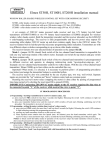
S~L600-1DC Sliding Ga-te Opener
Solar Compatible
~~
IMPORTANT SAFETY WARNINGSPlease read these important safety
warnings before installing or using this
product
•
Never let children operate or play with the controls.
•
Keep the remoter control away from the children.
•
Do not operate the sliding gate unless the gate is in full view and free from
objects such as cars, children or people.
•
Always keep the moving gate insight and away from any objects untii it's
completely opened/closed.
•
Do not disengage the slider gate motor to manual operation with anyone
or any other objects, including motor vehicles, within the doorway.
•
The slider gate must be well balanced. Sticking or binding gates can
falsely trigger the obstruction sensing of the unit.
•
All maintenance should be carried out by qualified personnel.
•
Hegularly test the slider gate motor to ensure that the obstruction sensor
unit is operating properly.
•
The slider gate motor has an electronic obstruction system that provides
safe and reliable operation. It's however a legal requirement in some
countries to also install a photo-electric sensor across the door way,
please check this requirement with your local distributor. However, it's
recommended to install this photo-electric sensor for all units.
Features
Your automatic Slider Gate
many features which you will
The components and materials
control board are of the latest
and highest quality.
Motor has
appreciate.
used in its
technology
The motor is used to drive a sliding gate,
with the moving speed of 12 meters per
minute. This gate-operator is powered by
AC220V, 50Hz. It is featured with powerful
starting strength, capable of overload at
short time. When it's overloaded, it's
protected electrically and mechanically.
In case of power failure, a key can be used
to release the motor and move the gates
manually. Following lists some of its key
features.
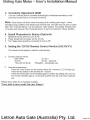
SECURITY CODE STORE
The Sliding Gate Motor uses' state of the
Microchip® technology in storing your
Slider Code Transmitter Security Code.
Up to 20 different transmitters can be
stored in the non-volatile memory device.
To store any code simply press the LEARN
button on the motor and press the
transmitter button twice. The codes can be
deleted at any time.
Security is enhanced because the fixed
and encrypted sections combined increase
the number of combinations to 7.38 x 10⁹.
There is no Dip switch on the motor which
can be visually seen and copied.
OPERATION
OPEN AND CLOSE DRiVE BUTTON
To operate the slider door simply press the
remote control handset or the wall mounted
switch for two seconds and the door will
automatically open/close.
Another feature developed to aid in the installation of the Slider Gate Motor is the
OISIC Button. This button is used to help
set the open and close limit positions. A
quicker time setting and a more precise
limit position can be achieved using this
system.
The gate can be stopped during on
opening or closing cycle by pressing the
remote control handset or wall switch. The
next actuation will move the gate in the
opposite direction.
SAFETY OBSTRUCTION REVERSE
While the gate is performing closing cycle
and it should hit an obstacle or be
restricted
in some manner, it will
automatically reverse.
The amount of force the gate should
encounter before reversing is adjustable.
The gate will automatically stop if restricted
whilst opening. The Safety Obstruction
Forces should be checked at least once a
month.
AUTO CLOSE MODE
The Slider Gate Motor can be programmed
to automatically close at a selected period
(eg. thirty seconds) after the door has
opened. A photo-electric beam must be
installed if this mode is selected.
PHOTO ELECTRIC BEAM
The Sliding Gate Motor has an input for a
Photo-Electric Beam to be connected for
extra safety protection.
SOLAR COMPATIBLE
This device is able to use 12V DC, 24V DC
or 12V solar panel to operate.
POWER FAILURE
Gates can be moved manually by
Inserting key and Allen key into motor
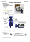
1. Installing the Gate Motor and Racks
(1) Safely secure the Drive Motor onto a stable concrete
slab/ground.
(2) Mount the required lengths of the Racks to the gate.
(3) Adjust the position of the racks so that the racks can be
engaged correctly with the Pinion gear. Ensure that the
Racks do not rest on the pinion gear and that it leaves an
allowance of 2mm between the racks and pinion gear.
"
2.1nstaliingJh~_ljmtt Switch Stonper
DO NOT switch on power see # 4
The Limit Switch Stopper is used to control the positions of the
gates,
(1) Screw the open and close Limit Switch Stoppers onto
the gear racks.
(2) When the stoppers are secured, use the Allen keys
provided to release the gear clutch and push the
sliding gates manually to predetermine the open and close positions. Then tighten the -'
gear clutch secure the gate positions .
..-
-------
(3) Connect leads to battery and using remote press # 1 to start motor
To see weather the gate slides smoothly
(4) Connect DC wire from 12v Plug Pack to motor NOW switch on power
(5) Adjust the position of the stoppers until the desired opening and closing
Positions are met
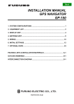
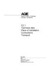
3. Setting the 12V DC Remote Control Handset
Receiver and REMOTE CONTROL fAR 1 Internal)
Press learn button on the Receiver for 1
second ( !.e.d will light)
Press required button on handset (Remote)
for 1 second
Press learn button on Receiver for 1 second
again ( !.e.d will turn off the light)
Repeat for all handsets (Remote
Your unit is now ready for use.
Enjoy!
learn
button
.
"r~
Sliding Gate Motor - User's Installation Manual
3. Sensitivity Adjustment (R20)
1. Turn the Overload Sensor clockwise (toward light) to decrease sensitivity or anticlockwise (toward heavy) to increase sensitivity.
Note:
Many factors will affect where this setting that including gate weight, incline,
prevailing wing conditions and desired auto reverse load .The gate may not open or close
fully if the "Overload Sensor' is to its maximum 'Light' position. Conversely, the gate may
not quickly auto reverse if the "Overload Sensor' is set to its maximum "Heavy' position.
4. Install Photoelectric Beams (Optional)
1
2
3
REMOVE the link wire from Com & PB ..
Power should then be drawn via the 12V DC
The Trigger wires should be connected to Com & PB.
5. Setting the 12V DC Remote Control Handset (GE-RCV1)
2. Connect cable as follows:
RED WiRE
BLACK
YELLOW OR BLUE
3.
12V DC +
OV DC - (Ground)
TRIGGER - (momentary n/o)
Hand set programming
- Press the 'Learn' button on the receiver device for 1 second (L.E.D will light up).
- Press the any button on the handset for 1 second.
- Press the same button on the handset again to confirm the setting, the L.E.D on
the receiver will flash approx. 10 seconds at which time the unit is then ready for
use.
Repeat above steps for all handsets available.
Vour unit is now ready for use. Enjoy!
Letron Auto Gate (Australia) Pty. Ltd.
(])
CJ
I1;lSLaW
+'
CI2
mY 12V
_.__
I
V
~F==JU2
'------J
II -
Q3
F2
IX; SLIDING GATE CONTROLLE~I FORCE
'--"CIO
&f~
0
+J3
20AI
.---.--J
Off
~\
12V 7AH
R7UGHT
c=> Oli O!
B
2PMa~~~
u')<'
15?i
09
-
Q5
-
ACl5V
IN
.----J,IC-l
. L.....J
C7
fL'':.
IJ.~Y-CL
~Cll
MOTOR 0 18Y
-'
PI P8
013
r
OP
l,J LOW
J2NO,
,.
NCD17
~.;~~wOO'
u3()~o:m~rr3'"
R16
"f"tD
2A
D14
{=:=J-
Rll
R5~-eJ-G~
DIOn
'
HEAVY
D'6~cdl~
DI'
B
~'
~
lo,)'
~
~
R
c; ~J~
G
RO
~
c6§fATUS
R20
D1n~_",~
Lead Acid Battery
L-J
ur
DYtlirl
VVoa
In;,:~
~U()
2
0
aD
N
0
RI2cr:·-~
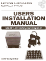
LIMIT SW-BuTI'tlN
OP COMCL COM
0
C
-
AC IN
15Vac
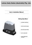
Close position
limit-sw
r
Black wire ~
I
Red wire +
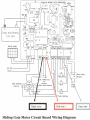
Sliding G~te Mptor(::ircuit ~oard Wiring Diagram
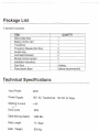
Package List
1
1
1
2
2
2
2
1
4 metres
Optional (recommended
Technical Specifications
Input Power
240V
Power Supply
15V AC Transformer
Starting Current
<4A
t> -.
Duty Cycle
50%
Gate Moving Speed
12M/ Min
Gate Length
To Spec
Gate
600 Kg
Weight
12V DC Or Solar
•
Clean and lubricate any moving components.
•
In case of rust, use some grease on it.
•
Ensure there are not binding / sticking of the gates which can falsely trigger the
obstruction sensing unit.
•
Regularly test the slider gate motor to ensure that the obstruction sensor unit is
operating properly.
Troubleshooting
·T;o~bjej·
"
;-_ ...
,..;
Too weak to move
the gate
Motor stops when
sliding gates are
blocked
Sliding gate fails to
move back after
opening/closing
Remote control
(Handset) not
workin
Pos$ible;PrOblem
(friction) clutch
,Causers)
Pressure on friction
clutch is too small
Pressure on friction
clutch is too big
Worm gear and worm
are blocked
Worm gear and worm
magnetic switch
Battery may be flat
(DC only)
Low voltage
(DC only)
Solution(;)/
Increase the pressure
by adjusting the
pressure screw
Reduce the pressure
by releasing the
pressure screw
Disintegrate clutch
with the key and push
gate back and readjust the position of
ma netic switch
Replace new battery
(DC only)