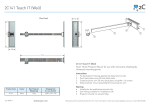
1
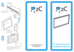
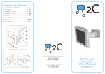
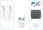
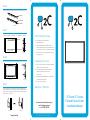
Step 6
There is a locking latch on the bottom wall mount only. (Fig 16)
Up Bracket
Bottom Bracket
Secure Button
(Fig 16)
Step 7
Fix the mounts onto the wall separately. (Fig 17-18)
(For 95” - height (h) = 1260mm & 105” - height (h) = 1430mm).
Up Bracket
h
Bottom Bracket
(Fig 17)
(Fig 18)
Step 8
Hook screen onto the top mount and bottom mount. (Fig 19-20)
(Fig 19)
(Fig 20)
Protecting Your Screen:
•
•
•
Keep away from direct sunlight or high temperatures.
Examine both the front and back surfaces before retracting into the case to make sure it is free of dust, dirt, insects or other foreign matter.
Use a soft brush or cloth to lightly remove any foreign particles.
Cleaning Your Screen:
•
•
•
Do not use any solvents, chemicals or abrasive cleaners on the screen surface.
Use a mild detergent with warm water to remove any marks on the surface or screen case. Always immediately dab the screen with a soft cloth to avoid soap marks. • Do not scrub the surface.
Step 9
To uninstall the screen, please press the latch towards the
wall to release bottom frame from bottom mount, then lift the
screen a little to release it totally from top and bottom groove
of the mounts. (Fig 21-22)
Warranty: 12 Months
For more information please go to
www.2cdisplays.com.au
or call 1300 730 025
(Fig 21)
Happy Viewing!
(Fig 22)
2C_FrameIT_Cinema_Flocked_Mar11_v1.1
2C Frame IT Cinema
Flocked Frame Screen
Installation Manual
Required (not supplied)
Step 1
Step 4
Lay each section of the frames on a tidy flat surface. (Fig 1)
Unfold screen fabric and insert the tensioning bars into the fabric grooves. (Fig 8-10)
Horizontal Frame
Vertical Frame
Electric Drill Screw Driver
3 x Screws
to suit Wall
Level
(Fig 1)
(Fig 8)
Step 2
Slide Fixing Lugs into grooves on the reverse side of frames.
(Fig 2 - 3)
Supplied
Fixing Lug
(Fig 9)
(Fig 10)
Step 5
(Fig 2)
Horizontal Frame (x 2)
& Vertical Frame (x 2)
Corner Brackets
(x 4)
Top Mount (x 1)
(Fig 3)
Step 3
Align fixing lugs and the eyelets provided on the fabric. Using the tensioning bar, pull fabric eyelets over the lugs. (Tip: Arrange
horizontal tensioning bars first then side tensioning bars). (Fig 11-15)
Insert both horizontal and vertical frame sections with the corner stakes. Ensure all joints are square and then lock off by tightening with the screws provided. (Fig 4-7)
Corner
Fixing Lug 95” x 24 / 105” x 28
10mm Corner
Screw
Bottom Mount (x 1)
(Fig 13)
Horizontal
Frame
Vertical
Frame
(Fig 4)
(Fig 11)
(Fig 5)
(Fig 14)
Side Tensioning Bar (x 2)
Horizontal Tensioning Bar (x 2)
5 x 40mm Tapping
Screw with Anchor
(x 8)
∅
(Fig 6)
(Fig 7)
(Fig 12)
(Fig 15)