1
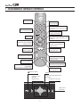
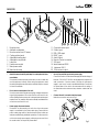
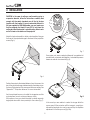
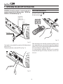
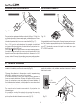
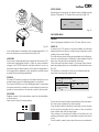
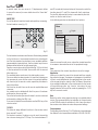
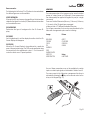
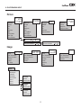
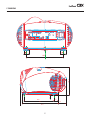
cod. 46.0533.000
User and Installation Manual
C3X - C3X LITE
1 TELECOMANDO E TASTIERA DI CONTROLLO
BACK LIGHT
Turn on the back light
STAND-BY
Switches off to stand-by
LIGHT
0-9 KEYS
Switch on from stand-by mode and allow direct
source selection
SOURCE
Display the source Selection Menu
ESCAPE
Deactivates the On Screen Menu
UP/DOWN/LEFT/RIGHT Arrow Keys
Navigate through andmake adjustement to the On
Screen Menu
Blank Screen
MENU
Activates the On Screen Display Menu
Navigates menu pages
MENU +
Activates the On Screen Display menus
Navigate menu pages
FREEZE
Freezes a moving picture
MEMORIES
Activates memories menu
ZOOM
F1
ZOOM
Active le réglage du zoom de l’objectif.
INFO
Displays the selected source information
and the projectors status
F2
FOCUS
Focus
Selects focus lens adjustement
VCR
Improves the video recorder signals quality
AUTO
Select Auto Adjust
(automatic optimisation of the displayed image)
ASPECT
Selects image Aspect ratio
Switches off to stand-by
▲,▼,◀,▶
Activates the On Screen
Display Menu
Navigates menu pages
Navigate through andmake adjustement to the
On Screen Menu
Deactivates the On Screen Menu
Display the source
Selection Menu
MENU
ESC
SOURCE
1 INTRODUCTION
Thanks to the new optical system based on three chip DMD™, the
C3X allows to take advantage from DLP™ technology, the Texas
Instruments technology.
Adaptation of the input signal resolution to the Projector resolution occurs without alterations of image quality, in accordance with an ample
choice of aspect ratios, including several definable by the user.
Each of the three DMD™ chip is dedicated to the modulation of one
of the primary colors coming from the optical prism, the refl ected
light, after combination by a second prism, is projected outside using
an appropriate lens system.
The technology of the C3X allows to obtain images without rainbow
effect or any other type of artefact, in order to enjoy an even more
realistic images.
All image adjustments can be performed with the remote control with
the aid of the On Screen Display; alternatively, the unit can be controlled
by from a home automation system through the serial port.
SIM2 carries out comprehensive functional testing in order to guarantee the maximum product quality.
For this reason, when you start using the product lamp operating
hours may already be at between 30 and 60.
The large number of inputs available (1 Composite Video inputs, 1 SVideo inputs, 2 Component or RGB inputs, 1 graphic RGB inputs, 1 DVI-D
input, 1 HDMI™ Input) ensures the system supports a wide variety of
analogue and digital sources: DVD players, VCRs, satellite and terrestrial
receivers, computers, game consoles, video cameras, etc.
In addition to the regular tests, the Quality Control department
performs additional statistical tests at the time of shipment.
In this case the packing may show signs of having been opened,
and the accumulated lamp operating hours may be slightly higher
than the hours associated with the standard tests.
Conversion of interlaced video signals to progressive signals by means
of prestigious DCDi™ technology produces fluid, natural, images free
of flicker and stairstepping artefacts.
Faithful reproduction of signals at higher resolutions (such as high
definition video and graphics) occurs without loss of information or
reduction of image sharpness thanks to the processor’s high pixel rate
signal acquisition capabilities.
TABLE OF CONTENTS
1 PRESENTATION
2 IMPORTANT SAFETY INSTRUCTION
3 DISIMBALLO
4 UNPACKING
5 SWITCHING ON AND OFF THE PROJECTOR
6CONNECTION
7CONNECTION PANEL
8 REMOTE CONTROL
9 ON SCREEN MENU
10 CLEANING AND MAINTENANCE26
11 TROUBLESHOOTING GUIDE26
3
4
7
8
10
10
12
14
15
12 OPTIONAL ACCESSORIES27
a - Technical specifications28
B - On Screem Menu29
b - dimensions
30
DLP and DMD are registered trademarks of Texas Instruments.
HDMI, the HDMI logo and High-Definition Multimedia Interface are trademarks or
registered trademarks of HDMI Licensing LLC
2 IMPORTANT SAFETY INSTRUCTIONS
This symbol indicates the possible electric
shock hazard associated with uninsulated live components in the interior of
the unit.
This symbol indicates the presence of important instructions regarding use and maintenance of the product.
ATTENTION:
To reduce the risk of electric shock, disconnect the power supply cable on the rear panel before removing the top cover of
the projector. Refer to trained, authorised personnel for technical assistance.
LAMP WARNING:
If the lamp should suddenly break with a loud bang, air the room thoroughly before using it. Do not replace the lamp: seek qualified technical
assistance from your nearest Dealer.
Environmental Information:
The product you have purchased contains extracted natural resources that have been used in the manufacturing process. This product
may contain substances known to be hazardous to the environment or to human health. To prevent releases of harmful substances
into the environment and to maximize the use of natural resources, SIM2 Multimedia provides the following information on how you can
responsibly recycle or reuse most of the materials in your ”end of life” product. Waste Electrical and Electronic Equipment (commonly
know as WEE) should never be disposed of in the municipal waste stream (residential garbage collection). The “Crossed-Out-Waste Bin”
label affixed to this product is in your reminder to dispose of your “End of Life” product properly. Substances such as glass, plastic, and
certain chemical compounds are highly recoverable, recyclable, and reusable. You can do your part for the environment by following
these simple steps:
1. When your electrical or electronic equipment is no longer useful to you, “take it back” to your local or regional waste collection
administration for recycling.
2. In some cases, your “end of life” product may be “traded in” for credit towards the purchase of new SIM2 Multimedia equipment.
Call SIM2 Multimedia to se if this program is available in your area.
3. If you need further assistance in recycling. Reusing, or trading in your “end of life” product, you may contact us at the Customer
Care number listed in your products user guide and we will be glad to help you withy our effort.
Finally, we suggest that your practice other environmentally friendly actions by understanding and using the energy-saving features of this
products (where applicable), recycling the inner and outer packaging (including shipping containers) this product was delivered in, and
by disposing of a or recycling used properly.
With your help, we can reduce the amount of natural resources needed to procedure electrical and electronic equipment, minimize the
use of landfills for the disposal of “end of life” products, and generally improve our quality of life by ensuring that potentially hazardous
substances are not released into the environment and are disposed of properly.
Prior to switching on the projector please read each chapter of this manual carefully as this manual provides basic instructions for using the projector.
The installation of the lamp assembly, preliminary adjustments and procedures that necessitate the removal of the top cover, must be carried out by authorised,
trained technicians. There are no user serviceable parts inside. To ensure safe and long term reliability please use power cables supplied with the projector.
Observe all warnings and cautions.
PROjector
5
6
4
2
3
1
20
7
13 12 11
+12
V
REM
OTE
1
USB
1.1
10
9
8
R/P
r
C/Y
RS2
32
3
B/P
b
HV
GRA
PHIC
S-V
ID
EO
S RG
B
4
2
VID
EO
REM
OTE
1
AUD
IO O
UT
MEN
U
HD
MI
1
5
ESC
SOU
RCE
0
I
19 18
1
2
3
4
5
6
7
8
9
10
Projection lens.
Aesthetic embrasures
Remote control front / IR sensor
Cooling air inlet vents
Adjustable levelling feet
Adjustable carry-handle
Lamp Box
Fused power socket
Main power switch
Main function keys
17
16
15
14
11 Composite video input
12 S-Video input
13 RGB / YPrPb input
14 HDMI™ input
15 Audio Output
16 Remote Control connector
17 VGA input
18 Serial interfaces RS232
19 Interfaces USB 1.1
20 12Vdc screen output
• Use only the specified type of mains power supply.
Connect the units to a mains electrical supply with rated voltage of
between 100-240 VAC, 50/60 Hz and equipped with a protective
earth connection. If you are unsure of the type of mains power
supply in your home, consult a qualified electrician. Ensure that
the power draw of the units is commensurate with the rating of
the electrical socket outlets and any extension cables that are
used.
• Read this manual carefully and keep it in a safe place for future
consultation.
This manual contains important information on how to install and
use this equipment correctly. Before using the equipment, read
the safety prescriptions and instructions carefully. Keep the manual
for future consultation.
• Do not touch internal parts of the unit.
The unit contain electrical parts carrying high voltages and operating at high temperatures. Do not remove the cover from the unit,
refer to qualified service personnel for all repair and maintenance
requirements. The warranty will be automatically invalidated if the
cover is removed from the unit.
• Connect the unit to a mains electrical supply
Make the connection as shown in Fig.2
HD
MI
1
5
ESC
SOUR
CE
0
I
• Power supply disconnect device.
The device for disconnecting the units from the mains power
supply is constituted by the power cable plug. Ensure that the
power cable plugs and the electrical mains socket outlets are
easily accessible during installation operations. To disconnect the
unit from the electric power supply, pull the plug to remove it from
the socket outlet. Do not pull the power cable.
100-240 Vac
50/60 Hz
Fig.2
• Prevent the unit from overheating.
In order to allow the Projector cooling, keep at least 40 cm
( 16”) of space between the rear of the projector and the
nearest wall or obstruction. Do not place the devices near
heat sources such as heaters, radiators or other devices
that generate heat (including amplifiers).
Do not obstruct ventilation openings.
Do not place the unit in confined, poorly ventilated positions
(bookcases, shelves, etc.).
Replace the safety fuse
Before making the replacement disconnect the appliance from the mains power supply.
The fuse compartment is close to the mains power connector (Fig. 3). Use a slotted screwdriver to remove the fuse
carrier (2) and replace the fuse (3). Insert a new spare fuse
(4). Use only T 5A H fuses.
5
ESC
• Do not expose the eyes to the intense light emitted by
the lamp.
Never look directly at the lamp through the ventilation
opening when the unit is switched on.
Risk of eyesight impairment. Ensure also that children do
not look directly at the lamp.
SOU
RCE
0
I
4
250 V
T 3.15A H
3
2
• Beware of the lens movements
Avoid positioning objects close the lens. The movements
( horizontal and vetical) could be obstructed by objects,
or damage may arise from the fall of the objects.
1
• Position the unit on a stable surface.
To avoid serious injury to persons and damage to property,
make sure the units are placed on a level, flat and stable
surface from which they cannot fall, tip over or slide. Pay
special attention if the units are placed on a trolley so that
they can be moved around. Ensure that the units are not
subjected to impact.
Fig.3
• Beware of power supply cables.
Position the power supply cables so that they do not constitute an obstruction. Position the power supply cables where
they cannot be reached by children. Install the units as
close as possible to the wall electrical socket outlet.
Do not tread on the power cables, make sure that they
are not tangled or pulled; do not expose the power cables
to heat sources; make sure that the power cables do not
become knotted or kinked. If the power cables become
damaged, stop using the system and request the assistance of an authorised technician.
• Do not insert objects through the unit openings.
Make sure that no objects are inserted inside the units. If this
should occur, disconnect the unit from the power supply
immediately and call an authorised technician.
• Energy Saving
When the system is left idle for a long period disconnect
the Projector from the main power supply.
This precaution allows to save energy and to prevent wear
and tear of the electronics devices.
• Disconnect the apparatus from the mains power supply
in the event of electrical storms and when not in use.
To avoid damage that could be caused by lightning striking
in the vicinity of your home, disconnect the unit in the event
of electrical storms or when the system will remain unused
for prolonged periods.
• Avoid contact with liquids and exposure to humidity.
Do not use the unit near water (sinks, tanks, etc.); do not
place objects containing liquids on top of or near the unit
and do not expose them to rain, humidity, dripping water
or spray; do not use water or liquid detergents to clean the
unit.
3 UNPACKING
3
4
To unpack the projector safely and easily please
follow steps 1 to 5, as per drawing (Fig. 4).
2
It is recommended that the carton and packaging is
retained for future use and in the unlikely event that
your projector needs to be returned for repair.
1
Fig.4
Package contents
Projector
The carton should contain the following:
- the projector
- the remote control
- four 1.5V AAA batteries (for remote control)
- three power cables for the projector (EU, UK,
USA)
- the user and installation manual.
User and
installation manual.
If any accessories are missing, contact your Dealer
as soon as possible (Fig. 5).
Remote control
1.5V AAA
batteries
Power cables
EU, UK, US
Fig.5
4 INSTALLATION
OM
ZO
CAUTION: In the case of ceiling or wall mounting using a
suspension bracket, follow the instructions carefully and
comply with the safety standards you will find in the box
together with the bracket. If you use a bracket different to
the one supplied by SIM2 Multimedia, you must make sure
that the projector is at least 65 mm (2-9/16 inch) from the
ceiling and that the bracket is not obstructing the air vents
on the lid and on the bottom of the projector.
ZOOM
F1
FUOCO
ZOOM
HELP
F2
FOCUS
AUTO
ASPECT
VCR
FU
OC
FU O
OC
FU O
OC
O
M
ZOO
O
ZO
Adjust the feet underneath to obtain a level position, lining up
the base of the projected image to the base of the projection
screen (Fig. 6).
M
ZOO
M
7).
+12V
USB
R/Cr
1.1
C/Y
CONT
3
ROL
B/Cb
(RS23
2)
HV
GRAP
HICS
S-VID
EO
RGB
4
2
S-VID
EO
REMO
TE
1
AUDI
O OUT
MENU
HDM
I1
5
ESC
INPUT
0
I
Fig. 7
L’immagine può essere centrata utilizzando le regolazioni di
spostamento motorizzato dell’obiettivo. Le traslazioni possono
essere sia verticali che orrizontali (Fig. 8).
+12V
USB
1.1
R/Cr
C/Y
CONT
ROL
3
(RS23
2)
B/Cb
HV
GRAP
HICS
S-VID
EO
RGB
4
2
S-VID
EO
REMO
TE
1
AUDIO
OUT
MENU
HDMI
1
5
ESC
INPUT
0
I
Fig. 6
Position the projector the desired distance from the screen: the
size of the projected image is determined by the distance from
the lens of the projector to the screen and the zoom setting. See
“Appendix C”: Projection distances” for more information.
+12V
USB
1.1
R/Cr
C/Y
CONT
ROL
3
(RS23
2)
B/Cb
HV
GRAP
HICS
Use the motorised lens zoom to adjust the image size and the
motorised lens focus to achieve maximum clarity.
With optimum focus you should be able to clearly see each
single pixel when within close proximity to the screen (Fig. 7).
S-VID
RGB
EO
4
2
S-VID
EO
REMO
TE
1
AUDI
O OUT
MENU
HDM
I1
5
ESC
INPU
T
������
Fig. 8
0
I
In the event you are unable to centre the image within the
screen area, tilt the projector until the image is correctly positioned.Any keystone error can be removed by the Keystone
adjustment in the Set up menu (Fig.8-8a).
+12V
USB
1.1
R/Cr
C/Y
CONT
ROL
3
(RS23
2)
B/Cb
HV
GRAP
HICS
S-VID
RGB
EO
4
2
S-VID
EO
REMO
TE
1
AUDI
O OUT
MENU
HDM
I1
5
ESC
INPU
T
0
I
TRA
PEZ
IO
20%
+12V
USB
R/Cr
1.1
CONTR
C/Y
OL
3
(RS232 B/Cb
)
HV
GRAPH
ICS
S-VIDE
O
RGB
4
2
S-VIDE
O
REMO
TE
1
AUDIO
OUT
MENU
+12V
HDMI
1
5
ESC
USB
INPUT
R/Cr
1.1
C/Y
CONT
ROL
3
(RS23
Fig. 8a
B/Cb
2)
HV
GRAP
HICS
S-VID
RGB
EO
4
2
S-VID
EO
REMO
TE
1
AUDI
O OUT
0
I
MEN
U
HDM
I1
Fig. 10
5
ESC
INPU
T
0
I
The Orientation adjustment in the Set up menu will allow the
projector to be used for desktop front, ceiling front, desktop rear
and ceiling rear installations (Fig. 9).
For rear projection the screen must be translucent.
For front projection, we recommend the use of screens with
low gain specifications
+12V
USB
1.1
R/Cr
CONTR
C/Y
OL
3
(RS232 B/Cb
)
HV
GRAPH
ICS
S-VIDE
RGB
O
4
2
S-VIDE
O
REMOT
E
1
AUDIO
OUT
MENU
+12V
HDMI
1
5
ESC
INPUT
USB
1.1
Fig. 9
R/Cr
C/Y
CON
TROL
3
(RS23
2)
B/Cb
HV
GRAP
HICS
S-VID
RGB
EO
4
2
S-VID
EO
REMO
TE
1
AUD
0
I
Fig. 11
IO OUT
MEN
U
HDM
I1
5
ESC
INPU
T
0
I
To activate an electric motorised screen a 12 Volt output is
provided at the rear of the projector. This can be connected
to a screen interface unit, which can be supplied by screen
manufacturers (Fig. 10).
The output is activated (Voltage: 12 Vdc) when the projector is
switched on and is de-activated (no Voltage output) when the
projector is in stand-by mode.
Some manufacturers offer screen-masking systems to help
frame the projected image and improve picture contrast.
These systems can be connected to output
, at the rear of
the projector (Fig. 11).
The use of high gain screens should be avoided due to their limited viewing angle, which is undesirable for a large audience.
Preferably, use a screen with black, non-reflecting borders,
which will perfectly frame the projected image.
Avoid light shining directly on the screen during projection as
this will reduce contrast and black level detail on the projected
image. For the true cinema experience best results are achieved with little or no ambient light.
Furniture and other objects with reflecting surfaces, as well as
light coloured walls should be avoided, as they are likely to
interfere with the screen’s characteristics.
5 SWITCHING ON AND OFF THE PROJECTOR
Switch on from stand-by
ACAUTION: Connect the projector to a power supply with a
nominal voltage within the following values: 100-240 Vac,
50/60 Hz. It must be earthed (Fig. 12).
Power Switch:
Position I: On
Position 0: Off
HV
GRA
By remote control: press
By keyboard: press
S-V
PHIC
S RG
IDE
B
O
4
2
S-V
IDE
REM
OTE
O
1
AUD
CON
TRO
UT
1
B/C
b
HV
S-V
IDE
S RG
B
O
4
2
S-V
IDE
REM
OTE
O
1
AUD
IO O
UT
ME
NU
HD
MI
NU
MI
2)
PHIC
ME
HD
S23
GRA
Fused
Power Socket
IO O
L (R
1
5
ESC
5
ESC
INP
UT
0
I
Power Plug
Fig. 14
Fig. 12
When switching on from stand-by, the projector will turn on the
lamp; after a brief warm up period the image will be displayed
(green LED on).The input automatically selected will be the last
one memorised prior to switch off (Fig. 14).
You may experience difficulties switching on the projector
shortly after switching off: the lamp may fail to come on as it
is too hot.
Upon switch on (in position I) the projector will initialise (red and
green LEDs on).
Followed by stand-by mode (red LED on) (Fig. 13).
ME
NU
HD
MI
1
5
ESC
HD
MI
2
6
INP
UT
0
I
Fig. 13
10
The fans will continue to work until the lamp has cooled down
(red and green LEDs flashing) and will stop automatically after
this period.
Switching off and returning to stand-by
By remote control: press
.
By keyboard: press key
.
When switching off, the projector goes in to stand-by memorising the input selection at the time of switch-off.
Status
Led red
Led blue
Logo Backlit
Initialisation
Blue Color
Standby
Red Color
On
Off / Blue Color (*)
Cooling
Blue Color
Overtemperature
Red Color
Fan Error
Red Color
: Off
: On
: Flashing
(*): selectable from OSD
6 CONNECTIONS
+12
V
To obtain the best performance from your projector, we recommend the use of good quality “video cables” to the various
signal sources (75 ohm Impedance).
USB
1.1
R/C
r
C/Y
RS2
32
3
B/C
b
HV
GRA
PHIC
S-V
ID
EO
S RG
B
4
2
S-V
ID
EO
REM
OTE
Poor quality cables will cause inferior picture performance.
1
AUD
IO O
UT
MEN
U
HD
MI
For optimum connectivity we recommend you follow these
simple steps:
75
- With exception of coaxial RCA/Phono type connectors, always double-check that the plug is inserted the correct
way round to avoid damaging the plugs or the sockets on
the projector (Fig. 15)
1
5
ESC
INP
UT
0
I
Fig. 15
- Remove cables by the plug and do not pull on the cable
itself.
- Position the cables carefully to avoid a trip hazard - especially in low light areas.
- Avoid tangled cables.
11
C3X - CONNECTION
3
RGB - YPrPb
4 GRAPHICS RGB
+12
V
USB
1.1
R/P
r
CON
2
C/Y
TRO
L (R
3
S23
2)
S-VIDEO
B/P
b
1
HV
GRA
PHI
CS
S-V
RGB
IDE
O
4
2
S-V
VIDEO
IDE
REM
OTE
O
5
HDMI
AUD
1
IO O
UT
ME
NU
HD
MI
1
5
ESC
SOU
RCE
O
I
1
2
Television receiver
DVD Player
Videorecorder
Camcorder
Game console
3
4
Television receiver
HDTV receiver
Videorecorder
Camcorder
Game console
Computer
DVD Player
5
DVD Player
HDTV receiver
Fig. 16
12
COMPOSITE VIDEO 1
definition video).
Progressive signals usually provide better quality than interlaced signals, but if the source features both progressive and
deinterlaced signal outputs it is good practice to compare
the quality of the pictures reproduced by the C3X in the two
cases: deinterlacing performed by the C3X (thanks to Faroudja
DCDi™ technology) is often more effective than that performed
at the source.
This input should be connected to a Composite Video signal
(CVBS) by means of a cable with an RCA connector.
The connector on the source is usually yellow and is frequently
labelled VIDEO.
Although other types of signals are preferable (since they allow
better picture quality), Composite Video signal is still very common, and nearly all television receivers, video-recorders, DVD
players, camcorders, etc., are equipped with it.
GRAPHICS RGB 4
S-VIDEO 2
This input should be connected to an RGB-type video or graphic
signal using a cable with a DB15HD type connector.
The signal source device (typically a personal computer or
game console) must be able to provide separate H/V synchronisation or composite H+V.
The video or graphic signals that can be connected to this input
can have horizontal scan frequencies (H-sync) of between 32
and 80 kHz and a vertical frequency (V-sync) of between 48
and 100 Hz. Image resolution can vary between 640x480 and
1600x1200 pixels (VGA, SVGA, XGA, SXGA, UXGA).
This input should be connected to an S-Video signal by means
of a cable with a 4-pin mini-DIN type connector.
The corresponding output on the source can be identified by
the labels S-VIDEO or Y/C.
Almost as widespread as Composite Video, S-VIDEO is preferable because it offers a clearer and sharper picture.
RGB / YPrPb 3
These inputs are composed of one set of 4 RCA connectors.
Each set of connectors is suitable for RGB and Component
signals.
HDMI™ 5
The HDMI™ (High Definition Multimedia Interface) integrates an
uncompressed high definition video signal with a multichannel
audio signal and allows the exchange of control data between
the video source and the C3X.
The HDMI™ input provides connection to video sources that use
the HDCP (High-Bandwidth Digital Content Protection) protocol
to protect contents.
Once the video source has been connected to the HDMI™
input, internal processing by the C3X separates the video
information from the audio information. Audio information is
then made available via an optical digital output with a female
TOSLINK connector in accordance with the S/PDIF standard.
RGB signals can have the following sync signals: composite
sync on the green signal (RGsB), H+V Composite Sync.
Connect the R, G, B outputs of the source to the respective R, G,
B inputs of the C3X (paying attention not to invert the positions)
and synch signals to the HV input.
When connecting the three sets of RCA connectors use the
colours as a guide: connector R is red, G is green, B is blue,
HV is white.
By using a suitable SCART to RCA (or BNC) connector adapter
cable, an RGB video signal from a source equipped with an
SCART connector can be connected to this input.
- Component signals should be connected to inputs Y, Cr and
Cb, taking care to observe the correspondence with the outputs
on the source. The connector colours can also be of help, as
shown in the table.
The video signals that can be connected to this input can
have horizontal scanning frequencies of 15 kHz (standard video
resolution), 32 kHz, or higher (progressive scanning video, high
13
Motorised projection screen output
12Volt
RS232 Interface connector
CONTROL RS 232
+12
V
+12
V
USB
1.1
R/C
r
C/Y
3
RS2
32
USB
B/C
1.1
R/C
r
C/Y
b
HV
GRA
RS2
32
PHIC
S RG
3
B/C
b
HV
GRA
B
S-V
PHIC
IDE
S RG
B
O
4
2
Fig. 17
S-V
IDE
REM
OTE
Fig. 18
The projector is equipped with two outputs (Voltage: 12 Vdc) for
motorised projection screen and screen masking systems. These
12V outputs should be connected to the appropriate screen
interface provided by the screen manufacturer (Fig. 17).
The +12V output is activated when the projector is switched
on (green LED on) and is de-activated when the projector is in
stand-by mode (red LED on).
The output
can be used to control a screen masking system;
its output can be set with the Screen control adjustment in the
Aspect menu. This output allows reduction in the area of a 16:9
screen, into a 4:3 format, by activating a screen masking system
(refer to screen manufacturer for further information).
It is possible to control the projector through a personal computer. First, load the appropriate projector control software onto
your PC, then simply connect this input to a cable from your
PC’s RS232 serial port.
8 REMOTE CONTROL
Insert the batteries, taking care to match the polarity, as indicated in the battery recess of the remote (Fig. 23).
Evitate di interporre ostacoli tra il telecomando ed i ricevitori
posti sul proiettore; ciò potrebbe rendere inefficace l’azione
del telecomando.
Change the batteries in the remote control if experiencing
difficulty in sending commands to the projector.
If the remote control is not to be used for a long period of
time remove the batteries. Replace all batteries at the same
time; do not replace one new battery with a used battery. If
the batteries have leaked, carefully wipe the case clean and
replace with new batteries.
The remote control sends commands to the projector via
infrared signals.
It is possible to control the projector by pointing the remote
control at the screen; the sensor at the front of the projector will
pick up the reflected infrared commands. (Fig. 19).
-
+
+
-
+
+
-
4 1.5V
AAA batteries
7
64#
3$S
$:
$0/530-34
#$C
)7
(3"1)*$43(#
47*%&0
47*%&0
3&.05&
"6%*0065
.&/6
)%.*
&4$
)%.*
*/165
0
I
Fig.19
14
1
2
Fig. 23
O
1
AUD
IO O
UT
9 ON SCREEN MENU
All system functions can be activated from the keypad or remote control with the aid of a practical and comprehensive
system of on screen menus.
of the < symbol.
As with the other inputs, you can now select the input just set
by pressing the ▶ key.
During the short time it takes to find the signal, a box appears
showing the signal requested. As soon as the signal is shown
in the box additional information is displayed concerning the
video standard (for video signals) or resolution (for graphic
signals), and format.
Fom the SETUP menu it is possible to choose to visualize or not
this information, for more details check the SOURCE INFORMATION
in MENU section.
INPUTS
The input selection menu (Inputs) is called by pressing 0 on the
remote control and, when no other menu is displayed, using
the ▲ and ▼ keys on the keypad. To select an input, scroll the
list with the ▲ and ▼ keys until the desired input is highlighted,
then press ▶.
Display of the input selection menu is terminated
by pressing the ESC key, or when the time allowed for displaying
the on-screen menu has lapsed (set in the Set-up Menu).
Input 5 can accept RGB and YPrPb signals with a scan frequency up to 32Khz.
Inputs can receive RGB and YPrPb signals, at 15 kHz, 32 kHz or
higher. The association between the input and the type of signal
(RGB or YPrPb) is made from the pull-down menu that appears
on the right of the < symbol after pressing the ◀ key (Fig. 20).
MAIN MENU
To access the main menu of the On Screen Display press
the MENU key on the keypad or the MENU+ or MENU- key on the
remote control.
The main menu is divided into four windows, PICTURE,
IMAGE, SETUP and MENU, in which the various adjustments are
grouped according to the frequency of use. Use ▲ and ▼ to
select the line corresponding to the adjustment you wish to
make (Fig. 21).
The various menus only offer the relevant adjustments in accordance with the type of input signal displayed (e.g. certain
typical adjustments for video signals, not necessary for graphic
signals, do not appear on the menus, and vice versa).
Source list/Edit source name
1 VIDEO 1
2
3
4
5
S-VIDEO 2
COMPONENT / RGBS 3
GRAPHICS RGB 4
HDMI 5
VIDEO 1
S-VIDEO 3 Yes
ACTIVA
COMP RGB 5
NAME
GRAPH RGB 9
HDMI 5
No
0ICTURE
Fig.20
In the pull-down menu it is also possible to choose the horizontal
frequency or use the AutoSync feature; in this case the system
detect the horizontal frequency signal (15KHz, 32KHz or higher)
automatically.
Input is capable of receiving YPrPb or RGB signals coming from
DVI-D sources.
The selection should be made from the drop menu following
the indications described above.
After selecting the source signal (by means of the ▲ and ▼
keys), press MENU+/MENU- to confirm and close the pull-down
menu; the value you have just set will be displayed on the right
Brightness
60
Contrast
Colour
Tint
Sharpness
Filter
Cinema Mode
Video Type
Noise Reduction
50
50
50
3
2
Off
Normal
Auto
Auto
VCR1
VCR2
Fig.21
Some adjustments (e.g. Brightness and Contrast) are associated
with a numerical value that can be varied within the set limits
using the keys ◀ e ▶. For others (e.g. VIDEO TYPE) you can choose
among three options presented on the same
◀ e ▶).
15
)MAGE
)MAGE
Aspect
Colour Temperature
Gamma Correction
Overscan
Position
Y/C Delay
Aspect
Colour Temperature
Gamma Correction
Overscan
Position
Y/C Delay
1
1
1
Normal
Anamorphic
Letterbox
Panoramic
Pixel to pixel
User 1
User 2
User 3
Fig.22a
Fig.22
Other adjustments (marked by the < symbol) provide submenus, which appear as a superimposed window in which the
selection is made with the ◀ e ▶ keys (Fig. 22-22a).
These submenus are accessed by pressing the ◀ key, while
exit and return to the upper level occurs by pressing MENU+/-.
Press ESC on the remote control or keypad to interrupt the
menu display or wait for it to disappear automatically after the
number of seconds set on the SETUP page.
Color
This control (also called Saturation) increases or decreases
the picture colour intensity. When set to zero, colour images
will be shown in black and white. Increasing the value, try to
find the point at which the colours look natural: suitable references include skin tones and grass in landscape shots.
Tint
Controls the purity of the colours. Basically determines the
red-green ratio of the picture.
Reducing the value will boost the red contents of the picture, increasing the value will boost the green tones. For this
adjustment use skin tones or a test pattern image with colour
bars as a reference.
PICTURE
This menu features the adjustments related to picture quality.
Adjustments that are not available for a given input do not
appear on the menu. Table 1 summarises the adjustments available for each input. For a complete overview of the on-screen
menus, consult the On screen menu layout in the Additional
Information section.
Sharpness
Use this adjustment to increase and decrease the level of
picture detail.
When the sharpness value is reduced the image details
appear less pronounced, while increasing the value raises
image definition, making the outline of objects sharper.
Note that an excessively high value may result in a ‘noisy’ picture
and the edges of objects may be unnaturally defined.
rightness
Use this control to adjust the image’s black level without
affecting white areas. Increasing the value will give more detail
in darker parts of the picture. For correct adjustment it may prove
useful to display the signal relative to the grey scale within which
the black level and the level immediately above it must be
separately identifiable. Alternatively use a scene composed of
black objects alongside other dark coloured objects.
Sharpness Mode
This allows you to select the type of processing associated
with sharpness adjustment. In the case of a progressive or interlaced video signal Video mode is advisable; with PC graphic
signals use Graphic mode.
Contrast
Use this control to adjust the image’s black level without affecting white areas.
To ensure correct adjustment, it may prove useful to display the
signal relative to the grey scale, within which the white level and
the level immediately below it must be separately identifiable.
Alternatively use a scene composed of well-lit white objects
surrounded by light coloured objects with lower level lighting.
Filter
This allows you to select the mode in which the input signal
is processed. Selecting the most appropriate value for a given
input signal ensures the best horizontal and vertical definition
and makes the picture sharper.
16
relative source is called.
You can also select the required aspect ratio by repeatedly
pressing the
key, or by pressing
and a numerical key
(1...8).
The following aspects are available.
Cinema Mode
In AUTO the deinterlacer recognises if the video signal source
is a movie film (obtained from a Telecine device with 3:2 or
2:2 pull-down) and applies a deinterlace algorithm optimised
for this type of signal.
If the video signal source is not identified as a film, or if you select
NO the deinterlacer applies a Motion compensated algorithm
optimised for video camera signals.
Normal: projects the image occupying the full height of the
screen while maintaining the aspect ratio of the input signal.
When the input signal aspect ratio is 4:3 black vertical bands
are displayed on the right and left of the picture.
Video Type
Activates a filter to improve stability of pictures from video recorders or DVD players. To toggle between Normal, VCR1 mode
and VCR2 mode press
on the remote control.
Anamorphic: allows a 16:9 picture to be displayed correctly.
Letterbox: serves to display 4:3 letterbox image (with source signal having black bands above and below the picture) so that
it fills the 16:9 screen and maintains the correct aspect ratio.
NOISE REDUCTION
This adjustments allows to choose the filter value for noise
reduction purposes.
As soon as this option is selected on the menu, the image is
divided in two parts.
In the left side the image is not altered by the filter, in the right
part the filter is activated.
This allows you to compare the effect of the filter.
It is possible to deactivated the filter (NOT ACTIVE), to use the automatic adjustments (AUTO) or to manually select (MANUAL) the
value suitable for the image with the VALUE adjustment.
In case of using the VALUE adjustement, it is enoght to select
to cursor below and set the value with the ◀ e ▶ keys of the
remote control.
Associated to the NOISE REDUCTION there is the possibility to use the
specific function (FLESH TONE CORRECTION) to make skin tone more
natural. Often the use of noise reduction filter slightly degrades
the image in those areas where skin tones are visible. With the
use of this function it is possible to maintain an excellent image
quality throughout the entire projected image.
Panoramic: this aspect stretches the 4:3 image, slightly cropping
the upper and lower parts.
Panoramic is ideal for displaying a 4:3 image on the 16:9
screen of the Display.
Pixel to Pixel: this aspect displays the image as it is input without
adapting it to the screen.
The image is projected in the centre of the screen and if its horizontal and/or vertical dimensions are smaller than the display,
Table 1
HDMI™
-
-
-
-
-
YCrCb
-
Tint
RGBS
Colour
Adjustments
Video
S-Video
RGB Grafico
RGBS 15kHz
YCrCb 15kHz
Inputs
Brightness
Contrast
IMAGE
This menu features adjustments relating to picture position,
aspect ratio, etc.
Sharpness
Sharpness Mode
Aspect
This adjustment allows you to change the dimensions and
aspect ratio (relationship between width and height) of the
displayed image. There are five preset aspects available and
three personalised aspects (with user-settable parameters). You
can select a different aspect for each source: the selected
aspect ratio will be automatically called the next time the
-
-
Filter
-
-
-
-
Cinema Mode
-
-
-
-
Video Type
-
-
-
-
Noise reduction
-
-
-
-
Flesh tone correction
-
-
-
-
Present only if the Video Standard is NTSC
17
it is bounded by vertical and/or horizontal black bands.
dark, medium, light grey, whites) in the projected image.
The projector is equipped with several gamma functions, allowing the best display of any image in relation to the video
source type, ambient light conditions, and the personal preferences of the viewer.
User 1, 2, 3: When none of the preset formulas are suitable, the
User formulas are available, with the facility for continuous
horizontal and vertical adjustment of picture size.
Screen Control
If an appropriate screen-masking interface is connected to the
12V output socket it is possible, for each aspect chosen, to reframe the screen to a variety of aspect ratios and screen sizes
(please refer to the screen manufacturer’s manual).
Verde
Color Temperature
The color temperature adjustment is made by positioning the
white point inside CIE cromaticity diagram.
The systems allows to choose from 36 predefined white points
inside the neutral color area (Fig.23).
9 The correlated color temperature varies along horizontal lines,
low temperatures are present in the right side (where the red
component is increased), in the left side of the diagram you
can find high temperature values ( in which blue component
is higher). The points along the lower horiziontal line (Fig.24)
represent colors that belong to the black body curve.
Rosso
)NFINITY
Blu
8
Fig. 24
The system provides 4 groups of gamma curves: Standard
(ST), Enhanced SIM2 (EN), Graphics (GR), and Personal. The
Standard curve is suitable for generic use: this curve is well
adapted to displaying images from video cameras, digital cameras, and films or photos from personal computers.
The Enhanced group is suitable for viewing movie films. The
Graphics group is suitable for displaying simple graphic images (desktop PC, CAD, PC presentations,…). The Personal
setting allows the gamma curve to be defined parametrically.
The user can select the coefficient that determines the shape
of the curve. Coefficient values between 1.5 and 2.2 serve to
emphasise details in darker parts of the picture although the
global perception of contrast is reduced. Values higher than
2.2 increase the global perception of contrast while attenuating the visibility of details in darker areas of the picture. With the
most common video sources a parameter value of 2.2 will
give high quality pictures with the right amount of contrast.
Along vertical lines the color temperature is constant but is different from black body curve, which mean if you select point
from the high part of the diagram you increase the green
componet, while low part of diagram cause an increase of
purple component.
Position
Use this adjustment to position the image vertically and horizontally. Determines the aspect ratio of the projected image.
These parameters do not normally require adjustment because
the system checks the input signal and automatically sets the
most suitable values.
However, if the image is not perfectly centralised it may prove
useful to request the system to repeat the input signal analysis
Fig. 23
Gamma Correction
Determines the system’s response to the grey scale, emphasising or attenuating the different grades of brightness (blacks,
18
and image positioning, calling the automatic control procedure
from the AUTO button on the remote control or keypad. When this
procedure is called it is helpful to have a white or light coloured
background on the screen in the current picture.
Enhanced SIM2 Gamma Standard Gamma
function
function
Table 3 - Gamma Correction
Frequency/phase
These adjustments, available for progressive signals and for
signals from PC, ensure correspondence between the number
of pixels making up the signal and the number of pixels making
up the projected image. These parameters do not normally
require adjustment because the system checks the input signal
and automatically sets the most suitable values.
However, if the image appears disturbed (loss of position within
the equidistant vertical bands or instability and lack of sharpness
on the narrow vertical lines) it may help to prompt the system to
repeat the input signal analysis and determination of the best
parameters by calling the automatic adjustment procedure
with the AUTO key on the remote control or on the keypad.
If the automatic procedure fails to have the required effect,
enter the frequency and phase values manually and approach the screen sufficiently to observe the effects of the
adjustments.
Y / C Delay
In the case of Video and S-Video signals, it may be necessary
to correct horizontal colour misalignment within the projected
image. For a given video standard (e.g. PAL or NTSC) the stored
value does not normally require further fine-tuning, unless the
source or connection cable has changed.
ST1
For generic uses.
EN1
Suitable for displaying images from
sources such as video cameras, digital
cameras or TV studios in high ambient
light conditions.
EN2
Suitable for displaying images from
sources such as video cameras, digital
cameras or TV studios in low ambient light
conditions.
EN3
Suitable for displaying movie films in high
ambient light conditions.
EN4
Suitable for displaying movie films in medium ambient light conditions.
EN5
Suitable for displaying movie films in controlled ambient light conditions.
G1
Suitable for displaying graphic images
(e.g. Windows Desktop) in medium ambient light conditions.
G2
Suitable for displaying graphic images in
controlled ambient light conditions.
Table 2
Graphics Gamma
function
Position
HDMI™
RGB Grafico
YCrCb
RGBS
RGBS 15kHz
YCrCb 15kHz
Adjustments
Video
S-Video
Inputs
-
Aspect
Frequency
-
-
-
Phase
-
-
-
Colour Temperature
Gamma Correction
Overscan
Y/C Delay
-
-
-
-
19
If the projected images needs to be centred, the LENS SHIFT (see
next paragraph) adjustment allows the projected image to be
moved vertically and horizontally, in relation to the centre of
the screen (Fig. 27).
SETUP
The setup menu contains less frequently used adjustments that
may be required during installation (e.g. On Screen Display
language selection or the display of Test Patterns).
ORIENTATION
Select the option that best describes the installation i.e. desktop
front, ceiling front, desktop rear and ceiling rear (Fig. 25).
+12V
USB
1.1
R/Cr
C/Y
CONTRO
3
L (RS232) B/Cb
HV
GRAPHI
S-VIDEO
CS
RGB
4
2
S-VIDEO
1
REMOTE
AUDIO
OUT
MENU
HDMI
1
5
ESC
INPUT
0
I
+12V
USB
1.1
R/Cr
C/Y
CONTRO
3
L (RS232) B/Cb
HV
GRAPHI
S-VIDEO
CS
RGB
4
2
S-VIDEO
1
REMOTE
AUDIO
OUT
MENU
HDMI
1
5
ESC
INPUT
0
I
Fig. 27
+12V
USB
1.1
R/Cr
C/Y
CONT
ROL
3
(RS23
2)
B/Cb
HV
GRAP
HICS
S-VID
RGB
EO
4
2
S-VID
EO
REMO
TE
1
AUDI
O OUT
The event you are unable to centre the image within the screen
area, tilt the projector until the image is correctly positioned.
Any keystone error can be removed by the Keystone adjustment in the Set up menu. The keystone adjustement helps to
compensate possible horizontal tilts of the projector.
MENU
HDM
I1
5
ESC
INPU
T
0
I
Fig.25
HORIZONTAL/VERTICAL KEYSTONE
To obtain maximum quality of the projected image, we recommend the installation of the projector on a level platform
parallel and central to the screen.
Adjust the feet underneath to obtain a level position, lining up
the base of the projected image to the base of the projection
screen (Fig. 26).
LENS
The ZOOM adjustment impacts on the motorized zoom lens
allowing to increase or decrease the dimension of the projected
image.
The FOCUS adjustment impacts on the motorized lens focus,
allowing to obtain the highest definition on the projected image,
an accurate focus setting should allow the viewer to distinguish
each pixel that create the image one from another.
In association with the ZOOM, FOCUS and LENS SHIFT adjustments the C3X system provides three test patterns to be used
if there is no suitable signal available to set up these parameters.
The LENS SHIFT adjustment allows to move horizontally (keys ◀
and ▶) and vertically (keys ◀ and ▶) the lens, in order to center
the image.
KEY
STO
20%
NE
+12V
USB
1.1
R/Cr
C/Y
CONT
ROL
3
(RS232 B/Cb
)
HV
GRAPH
ICS
S-VIDE
RGB
O
4
2
S-VIDE
O
REMO
TE
1
AUDIO
OUT
MENU
HDMI
1
5
ESC
INPUT
0
I
Fig.26
20
OM
ZO
FACTORY DEFAULTS
Reconfigures the projector to original factory settings except
Position, Orientation, Y/C Delay, Zoom and Focus (Fig. 29).
ZOOM
F1
FOCUS
ZOOM
HELP
F2
FOCUS
AUTO
ASPECT
VCR
FO
M
ZOO
CU
FO S
CU
FO S
CU
S
M
ZOO
Confirm?
No
Yes
OM
ZO
Fig. 29
ON SCREEN MENU
+12V
USB
1.1
R/Cr
CONTR
C/Y
OL
3
(RS232 B/Cb
)
HV
GRAPH
ICS
S-VIDE
RGB
O
4
2
S-VIDE
O
REMOT
E
1
AUDIO
OUT
MENU
HDMI
1
5
ESC
INPUT
0
I
Language
Lists the languages available for the On Screen Display menus.
Fig. 28
SOURCE LIST
In order for the C3X system to be more flexible, the following
described functions allow to modify the input selection menu
making it more user friendly.
The main window shows all the inputs available on the Projector.
If one or more inputs are not utilized, it is often helpful to blank
them from the input list (accessed with the 0 key).
Once the input has been chosen, in the drop menu that appears by pressing the ◀ key, it is possible to activate the source
(Fig. 30).
The exclusion or activation of the source will automatically
renumber the remaining active inputs.
In the initial phase of installation the configurable keys (F1, F2)
serve as optical zoom and optical focus (Fig. 28).
LAMP POWER
If your room is especially dark, the images from the system C3X
could result execessively bright. In order to enjoy wonderful
images, the ECOMODE function activation allows to re du ce
the power used to feed the lamp. In this way, the brightness of
the image will be adapted to your projection conditions and
a grater life lamp will be guaranteed.
POWER ON
If active (AUTO) allows to power up the system directly from the
power feeder, once the initializing phase is completed.
If not active (STAND-BY) once the initializing phase is completed
the system remains in a stand-by mode waiting to receive the
power on command from the remote control or the key pad.
Source list/Edit source name
1 VIDEO 1
2
3
4
5
TEST PATTERNS
Displays a series of five test patterns, useful for the installation
of the projector.
Press ◀ and ▶ keys to browse pattern.
S-VIDEO 2
COMPONENT / RGBS 3
GRAPHICS RGB 4
HDMI 5
VIDEO 1
S-VIDEO 3 Yes
ACTIVA
COMP RGB 5
NAME
GRAPH RGB 9
HDMI 5
No
Fig.30
The inputs with an active video signal (visible in the input selection menu) are marked with a check symbol.
It can be also helpful to identify the input with a name chosen
by the user (for example with the name of the connected
source) rather than with the signal type.
Once chosen to have the input visible, in the drop menu, by
selecting the Name option it is possible to rename the source
in use.
This will make it easier to remember the source connected to
21
a specific input. You can use up to 12 alphanumeric letters
to name the source (for more details check the “Insert text”
section).
and F2 is made by the ◀ and ▶ keys of the remote control; the
function given to F1 and F2 is chosen with the ▼ and ▲ keys.
The function delivered by the key is memorized by the intersection on the line and column.
Insert text
You will be able to insert text easily and rapidly by accessing
the text insertion menu (fig. 31).
In the following window are described the 6 options
-ENU
%DITSOURCENAME
???????????
#ANCEL
#ONFIRM
!"#
$%&
'()
*+,
-./
0123
456
789:
Language
English
Source list
F1/F2 keys
Source info
Zoom
OSD Backgroung
Focus
OSD Position
Magnification
OSD Timeout Blank
F1 F2
Colour temperature
Gamma correction
Fig.31
Fig.32
The text insertion mode remains the same if text is being inserted
for the first time or if a previously inserted name is being edited. The letter insertion can be done in any available position
(represented by horizontal lines). Use the ◀ and ▶ keys to move
between letters either left or right respectively.
Press the numeric key matching the letter (Fig. 32), the first click
of the key selects the first letter, the second click the second
letter and so on.
The available letters are shown in the text insertion menu.
Once one letter has been inserted, to insert the following one
it is necessary to move with the cursor in the next right position
with the ▶ key of the remote control, repeat this procedure to
insert other letters.
Use the ▲ key to switch from small case to capital letters and
viceversa.
Any mistake can be deleted with the ▼ key once it has been
positioned on the wrong letter.
Once the text insertion process is finished, it can be confirmed
and saved by clicking the MENU+ key.
If you want to delete the modifications use the MENU- key of the
remote control.
Zoom
Allows to access the optic zoom, where the ◀ and ▶ keys allow
to increase or decrease the size of the projected image.
Focus
Once selected, the ◀ and ▶ keys allow to focus the image.
Magnification
Allows you to select the area to be viewed and then magnify
the projected image. The degree of enlargement is selected
in Zoom mode (identified by a magnifying glass in the centre
of the image) using the ◀ and ▶ keys. The area of the picture
to be enlarged is selected in Pan mode (symbol in the centre
of the picture) using the ◀,▶, ▼ and ▲ arrow keys. You can
toggle between Zoom and Pan mode by pressing the F1/F2
key on the remote control.
Blank
Blanks the active video signal producing a completely black
screen. Once pressed the key an indication of a few seconds
on the OSD will confirm its activation. A click of any other key of
the remote control allows to restore the previous settings.
F1/F2 keys
This allows to assign different functions to the remote control
keys, named F1 and F2.
The window is made of 6 options, once for each line and by
two columns showing the F1-F2 keys. The choice between F1
Color temperature
The following click of the key (F1 or F2) allows to choose between
the different color temperatures available. High, Mid, Low, User.
22
Gamma correction
The following click of the key (F1 or F2) allows to choose between
the different gamma curves available.
MEMORIES
The main parameters of the image may be saved in distinct
groups of values (known as ‘Memories’); these parameters
can subsequently be applied all together by way of a single
command.
There are 3 distinct Memories (Memory 1, Memory 2, Memory
SOURCE INFORMATION
When active (YES) each source change will show the information
related to the signal. If not active (NO) there will be no information
on the selected source..
3) for each of the 25 signal types managed:
making a total of 75 different available Memories.
The image parameters that can be saved/recalled by the
Memories management system are the following:
OSD BACKGROUND
Determines the type of background for the On Screen Display.
Image
OSD Timeout
Use this adjustment to set the display time after which the On
Screen Display will disappear.
Picture
BRIGHTNESS
ASPECT
CONTRASTCOLOR TEMP.
COLOR
OVERSCAN
TINT
GAMMA
SHARPNESS
FILTER
SHARPNESS MODE
VIDEO TYPE
Setup
NOISE REDUCTION
LAMP POWER
OSD Position
Allows the On Screen Display to be positioned in a particular
area of the projected image. The OSD can be positioned using
the arrow keys for fine adjustments or keys 1...9 on the remote
control to select one of 9 preset positions.
Some of these parameters may not be available for certain
inputs or certain input signals, as indicated in Tables 4 and 5.
The menu page for the Memories management functions is
activated by pressing the
key on the remote control or the
◀ key on the keypad (Fig. 33).
CON
TRO
L (R
S23
2)
B/C
b
HV
GRA
S-V
PHIC
IDEO
S RG
B
4
2
S-V
IDEO
REM
OTE
1
AUD
IO O
UT
MEN
U
HD
MI
1
5
ESC
INP
UT
0
I
Fig.33
23
The operations that can be performed on each memory selected are described here below.
been completed successfully, the message Memory 1 initialised is displayed at the bottom of the screen and the letter
‘I’ appears to the left of the name of the memory.
Save a memory
To save the current values of the image parameters in Memory
1, use the ▼ and ▲ keys to move to line ‘1’ and then open the
pull-down menu by pressing the ◀ key (Fig. 34). Then select
the option ‘Save current settings’. To confirm that the operation
Rename a memory
It is possible to assign a name to each Memory. To assign
a name (with a maximum length of 12 alphanumeric characters) to a Memory, select the option ‘Rename’ from the
corresponding pull-down menu. Enter the text following the
procedure indicated in paragraph source list.
1 VIDEO
Restore Current Settings
On entering the Memories menu, a copy of the current settings
is saved in a temporary menu (labelled with 0 - AUTO). Once one
or more memories have been recalled, you can restore the
settings that were effective at the moment the Memories menu
was accessed by selecting 0 - AUTO. However, this operation
must be completed before the Memories menu page disappears (30 seconds after the last operation commanded from
the remote control or the keypad). The next time it appears,
the temporary memory will contain new information that takes
into account any Memories selected the penultimate time the
‘Memories’ page was accessed.
2 S-VIDEO
3 COMP/RGB(YCrCb 15KHz)
3 COMP/RGB(RGB 15KHz)
4 COMP/RGB(YCrCb 32KHz)
4 COMP/RGB(RGB 32KHz)
5 GRAPHICS RGB
6 HDMI
has been completed successfully, the message Current settings
saved in Memory 1 is displayed at the bottom of the screen and
the letter ‘S’ appears to the left of the memory name. The same
procedure is used to save parameters in Memories 2 and 3.
Memory 0 (- AUTO) can be used even when you do not wish
to enable the Memories management function for the signal
currently in use. Once Memory 0 has been selected, when a
source is chosen, the settings that were effective at the time
the Memory was previously recalled will be automatically
applied.
-EMORIES
0 Auto
1
S Save current settings
2
I
Save initial settings
3
S MEMORIA
Rename 1
INFO
Displays the current status of the projector and information
concerning the projected video/graphic signal.
This function is displayed on pressing
on the remote control
(or, in the absence of the On Screen Display, the ▶ key on the
remote control).
Fig.34
Recall a memory
To recall a Memory, select the desired line and press ▶. The
parameters saved in the selected Memory will be applied to
the image displayed and a message will appear to confirm
the operation Memory 1 recalled. The Memory recalled will
be associated with the source and signal type, and will be
automatically recalled every time that particular source and
signal type combination is selected.
Save default settings
To restore the original values to a previously modified Memory,
select the line corresponding to the Memory in question and
open the pull-down menu ( ◀ key). Then select the line Initial
settings saved in Memory 1. To confirm that the operation has
24
QUICK MENUS
The quick menus provide access to the main adjustments
that affect image quality, without calling the main On Screen
menus.
Brightness, Contrast, Colour, Tint, Sharpness and Filter adjustments
appear at the bottom of the screen one after the other when
the ▼ and ▲ keys are pressed .
MESSAGES
The following messages may appear during operation of the
system:
No signal
The system does not recognise any signal applied to the selected input. In this case:
• Make sure the selected input is connected to a video or
graphic signal and that that source is functioning correctly.
• Check the condition of the cables used to connect the
system to the various sources.
• Make sure the video or graphic signals supplied by the source are compatible with the system’s technical specifications
and, in particular, with those of the selected input.
Out of range
This message appears when either the resolution or the vertical/
horizontal frequency of the input signal exceeds C3X specifications (e.g. a QXGA graphic signal) or when an input is supplied
with an incompatible signal (e.g. after setting the components
input to YPrPb 15kHz a progressive signal is connected).
Substitution lamp
If the lamp hours exceed the 90% of the life lamp, at every
switching on , a brief message appears on the screen to remember the need of replacing it in a short time.
If the lamp life is greater than 100% the message above
persists until the ESC key is pressed.
25
10 CLEANING AND MAINTENANCE
The Projector do not require internal cleaning.
There is no user serviceable parts inside the projector.
Please refer all service requirements to qualified personnel.
Cleaning the lens:
The lens may be cleaned with a very soft, non-abrasive small
brush, in order to remove dust particles. Alternatively, use a soft
dry cleaning cloth (of the type used for camera lens cleaning)
to remove fingerprints and grease marks.
Cleaning the projector’s cover:
Use a soft slightly damp cloth. Do not use abrasive cleaners,
solvents or other harsh chemicals, as this will damage the
finish of the cover. Avoid direct cleaning of the rear panel’s
screen-printing.
11 TROUBLESHOOTING GUIDE
No power (Green and red LED are OFF)
•Check the cooling air inlets or air outlets on the units are
not obstructed and the room temperature is below 35°C
(95°F).
•Check the power switch at the rear: it must be in position I.
•Check if the power cable has been connected correctly to
a working socket.
•Check the power socket fuse, at the rear of the projector.
•Replace the fuse on the mains socket with an identical type
(T 5A H)�����������
(Fig. 2).
•Should the problem persist, seek authorised technical assistance.
Image is disturbed, unstable or noisy
•Verify compatibility of video/graphic signals with the technical
specifications of the projector.
•Check the integrity of cables connecting projector to various
sources.
•If the signal source is a terrestrial broadcast (via a VCR) check
that the receiving channel has been correctly tuned in and
that the aerial system is in good working order.
•Should the problem be present with a signal coming from a
video-recorder, ensure that the videotape is an Original “first
generation” copy and in good condition.
•Adjust the VCR’s tracking control for optimum picture performance. Ensure the VCR mode is active in the Picture
menu.
The lamp is not coming on
•Allow a few minutes pause between switching off and turning
on again (from stand-by). This will allow the lamp to cool down
sufficiently.
•If the lamp doesn’t come on – even though the projector has
had sufficient time to cool down – seek technical assistance
from your nearest Dealer.
No image
Incomplete image along borders (vertical and horizontal)
•Check that the selected input is actually connected to a
active video or graphic signal.
•Check that the above source actually works.
•Verify compatibility of video/graphic signals with the technical
specifications of the projector.
•Check the integrity of cables used to connect various sources.
•Compare compatibility of video/graphic signals and technical specifications of your projector.
•Press A on your remote control or AUTO on keypad to execute
automatic adjustments.
26
•Adjust the horizontal and vertical position of projected image
by selecting Position on the Image Adjustments menu.
•Adjust the width and height of image, selecting Aspect in the
Image Adjustments menu.
•Adjust the Overscan value in the Image/OVERSCAN menu.
Video Image showing colour misalignment on vertical
details
•Verify compatibility of video/graphic signals with technical
specifications of your projector.
•Adjust Y/C Delay settings in the Image Adjustments / Advanced
Settings to reduce colour misalignment. For best results use
an external colour bar test pattern source.
Image too dark, too pale or unnaturally coloured
•Verify compatibility of video/graphic signals with technical
specifications of your projector.
•Go to Picture menu, select and regulate any of the following,
accordingly: Contrast, Brightness, Color, and Tint.
•If necessary, reset the Color Temperature and Gamma Correction
(found on the Image Adjustments / Advanced Settings menu).
Remote control does not work
•Check the batteries and for correct polarity.
•Ensure that the area between the infrared sensor (front of
projector) and the remote control is free of obstruction.
•Ensure that infrared sensors (front and rear of projector) are
not exposed to intense light levels.
Graphic image with poor quality vertical detail
•Verify compatibility of video/graphic signals with technical
specifications of your projector.
•Press A on your remote control or AUTO on keypad to execute automatic adjustments.
•Adjust Frequency and Phase parameters, found in the
Image Adjustments menu, to optimise vertical detail of the
projected image.
12 OPTIONAL ACCESSORIES
You can purchase the following optional accessories at your
Dealer:
CAUTION: for ceiling installation, by means of suspension bracket,
carefully follow the instructions and safety instructions recommended by the Manufacturer in the bracket’s literature.
- Ceiling Bracket Kit.
- Type of lens
Rivolgetevi sempre al vostro centro di assistenza per sostituire
l’obiettivo. Utilizzate solo accessori originali o approvati da SIM2
Multimedia.
Up to six types of lenses are available to accommodate different
throw distances and your specific installations. See Additional
Information for more details on throw distances and the dimensions of the image projected. To change the lens, contact
always your nearest dealer.
Use only original, or SIM2 Multimedia approved, accessories.
27
A Technical specifications
ELECTRICAL
GENERAL PROJECTOR
Input signals:
• 1 COMPOSITE VIDEO (CVBS)
RCA type connectors, gold-plated
1,0 Vpp / 75 Ω, negative synchronisation
• 1 S-VIDEO (Y/C)
4-pin mini-DIN connectors
Y: 1,0 Vpp / 75 Ω, negative synchronisation
C: 0,286 Vpp / 75 Ω, [NTSC nominal burst level]
0,3 Vpp / 75 Ω [PAL, SECAM nominal burst level]
• 1 COMPONENTI (Y/Pr/Pb/H/V) - RGBS
1 set of 4 RCA connectors
- Components signal Y: 1,0 Vpp / 75 Ω, negative or 3-level synchronisation Pr,Pb:0,7 Vpp / 75 Ω
- RGB signal
R,B:0,7 Vpp / 75 Ω
G: 0,7 Vpp / 75 Ω, HV Sync
1,0 Vpp / 75 Ω,negative or 3-level synchronisation
TTL positive or negative, 0,3-5 Vpp / 1 kΩ
• 1 RGBHV (analogue RGB)
female DB15HD connectors
R,B: 0,7 Vpp / 75 Ω
G:0.7 Vpp / 75 Ω, separate H/V Sync or H+V Sync
1.0 Vpp / 75 Ω, negative or 3-level synchronisation TTL positive or negative, 0.3-5 Vpp / 1 kΩ
• 1 HDMI™
Power supply cable:
Supply: Consumption:
Fuse: Dimensions of projector: Weight of projector:
Operation temperature: Transportation temp.:
Storage temperature:
Humidity: Safety: Transportability: Compatibility:
Transportation:
Control: Horizontal frequency: Vertical frequency: Video standards: High definition video: Graphic standards: Deinterlacer: Colour temperature: Outputs: Remote control, via RS232 from PC or home automation devices, USB 1.1
from 15 to 80 kHz (up to UXGA, 85 Hz)
48 -100 Hz
automatically selected (PAL B, G, H, I, M, N, 60, SECAM, NTSC 3.58 and 4.43)
ATSC HDTV (480p, 720p, 1080i,)
VGA, SVGA, XGA, SXGA, UXGA
Faroudja chipset, DCDi™, 3:2 pull-down sequence conversion
from 6500 to 10000 K
- 2 12-V jack connector outputs (1 active
with system powered on, 1 active with 16:9 aspect ratio selected)
- 1 Optical S/PDIF audio output Toslink connector
28
(EU, UK e US); lenght 2m
da 100 a 240 Vac, tolerance +/- 10%
frequency from 48 to 62 Hz
350 W max (240 W Max C3X LITE)
T 5 A H, 5 x 20 mm
435x190x430 mm (LxAxP)
11 kg
10 to 35°C
-15 to 55°C
-15 to 55°C
20% a 95% humidity non-condensing
EN 60950
desktop equipment
EN 55022 Class B
EN 55024
EN 61000-3-2
EN 61000-3-3
IEC 68-2-31, IEC 68-2-32
B On screen menu layout
Picture
Video • S-Video
[NTSC]
YCrCb15kHz
RGBS
15kHz
Brightness
Contrast
Color
Tint
Sharpness
Filter
Cinema Mode
Video Type
Noise reduction
Brightness
Contrast
Color
Sharpness
Filter
Cinema Mode
Video Type
Noise reduction
Not active
Video • S-Video
[PAL, SECAM]
Auto
Flesh tone correction
YCrCb
Manual
On
Off
Image
Video • S-Video
Aspect
Color Temperature
Gamma Correction
Overscan
Position
Y/C Delay
Normal
Anamorphic
Letterbox
Panoramic
Pixel to Pixel
User 1
User 2
User 3
Value
Flesh tone correction
On
Off
YCrCb
RGB
RGB Grafico
YCrCb 15kHz
RGBS 15kHz
HDMI™
Aspect
Color Temperature
Gamma Correction
Overscan
Position
Frequency
Phase
Aspect
Color Temperature
Gamma Correction
Overscan
Position
Aspect
Brightness
Contrast
Sharpness
Sharpness Mode
Brightness
Contrast
Color
Tint
Sharpness
Sharpness Mode
Gamma Correction
Color Temperature
High
Medium
Low
User
Horizontal
Vertical
Screen control
Horizontal
Vertical
Screen control
Aspect
Color Temperature
Gamma Correction
Overscan
Graphic NTSC
NTSC Enh
Graphic Enh
PAL SECAM
PAL SECAM Enh
Red Offset
Green Offset
Blue Offset
Red Gain
Green Gain
Blue Gain
Horizontal
Vertical
Screen control
Setup
Orientation
RGBS
RGB Grafico
HDMI™
29
Floor
Horizontal
Vertical
Screen control
Setup
Orientation
Keystone
Lens
Lamp Power
Power ON
Test patterns
Initial settings
Zoom
Focus
Lens Shift
Auto
Stand-by
English
Italiano
Français
Deusch
Español
Português
Menu
Language
Source list
F1/F2 keys
Source info
OSD background
OSD Position
OSD Timeout
1
2
3
4
5
Floor
Floor-rear
Ceiling
Ceiling-rear
Horizontal
Vertical
Yes
VIDEO 1
S-VIDEO 2
COMPONENT / RGBS 3
GRAPHICS RGB 4
HDMI 5
No
Zoom
Focua
Magnification
Blank
Color temperature
Gamma correction
VIDEO 1
S-VIDEO 2
COMP RGB 3
GRAPH RGB 4
HDMI 5
F1 F2
Active
Yes No
Name
Edit source name
___________
Cancel
-
Confirm
+
()?@
1
ABC
2
DEF
3
GHI
4
JKL
5
MNO
6
PQRS
7
TUV
8
WXYZ
9
0
Memories
Memories
0 Auto
1
S MEMORY 1
2
S MEMORY 2
3
S MEMORY 3
Edit memory name
Save current settings
Save initial settings
Rename
___________
30
Cancel
-
Confirm
+
()?@
1
ABC
2
DEF
3
GHI
4
JKL
5
MNO
6
PQRS
7
TUV
8
WXYZ
9
0
C DIMENSIONS
42
42
9.5
195.6
285.3
280.6
336
41.5
72.6
431.4
31
SIM2 Multimedia S.p.a. • Viale Lino Zanussi, 11 • 33170 Pordenone - ITALY
Phone +39.434.383.253-256 • Fax +39.434.383260-261
www.sim2.com • e-mail: [email protected]
SIM2 USA Inc. • 10108 USA Today Way • 33025 Miramar FL - USA
Phone +1.954.4422999 • Fax +1.954.4422998
www.sim2usa.com • e-mail: [email protected]
SIM2 Deutschland GmbH • Gewerbepark, 17 D-35606 Solms
Phone 0800.800.7462 • Fax 0800.900.7462
www.sim2.com • e-mail: [email protected]
SIM2 UK LTD • Steinway House Worth Farm,
Little Horsted Nr. Uckfield, East Sussex TN22 5TT
Phone +44.01825.750850 • Fax +44.01825.750851
www.sim2.co.uk • e-mail: [email protected]
SIM2 Multimedia is certified
• Due to the constant product development, specifications and design might be subject to change without notice.