1
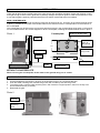
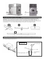
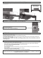
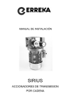
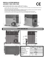
INSTALLATION MANUAL
AG2000 // 800-1000-1600
MOTOR REDUCER FOR SLIDING GATES UP TO 1600 kg
-
The AG 2000 motor reducer is made up of two solid die-cast aluminium blocks and an ABS lid that houses the
electric motor and the control equipment.
The version complete with control equipment is capable of controlling the different function logistics, adjusting
the anti-crushing coupling and all the safety and control devices.
The 800 kg version is lubricated with an oil bath and is not equipped with mechanical clutch.
The 1000-1600 kg versions are lubricated with an oil bath and equipped with mechanical clutch.
SIZES IN MILLIMETRES
224
30
235
145
90
291
35
Technical features:
Supply voltage
Condenser
Motor revolution speed
Pinion module
Thermal circuit
breaker intervention
Functioning temp
Lubrication
Mechanical clutch
Weight
135
800kg. 1000-1600kg 1600TRIF.
230V
400V
12µF
16µF
-----1400rpm
M4-16
Grease
NO
140°C
-25°/+70°C
oil bath
YES
13Kg
INSTALLATION
PRELIMINARY INSTRUCTIONS
Check that all the fixed and mobile parts of the gate comply with regulation standards. Check that the door is solid
and rigid enough, that the inferior guide flow is perfectly straight, the superior guide is made and positioned in such
a way that the gate is perfectly vertical and that the limit switch mechanical stops are installed.
WITH COUNTERPLATE:
Prepare a cement base raised at the same ground level at least 40-50 mm, according to the measurements shown
in photo 1. Prepare for the outlet of two flexible tubes for the electrical wires in correspondence to the entrance of
the counterplate.
The counterplate can be fixed to the ground using pressure screws in the corresponding fixing holes on the ground.
Fix the AG2000 with the two screws supplied on to the counterplate, following the measurements shown in photo 1.
Photo 1
Counterplate
55
Holes for flexible tubes
Gate
35
Holes for
fixing to
the ground
145
Holes for
fixing motor
Rack
300
Wheel
19
Counterplate
Guide
Cement base
WITHOUT COUNTERPLATE
When not using the counterplate, fix the motor to the ground using 2 or 4 inserts.
UNLOCKING SYSTEM WITH KEY
In case of power failure, the motor can be unlocked by activating the unlocking lever as follows:
1. Put the supplied key (as shown in photo 2) in the keyhole turning it in a clockwise direction.
2. Push the metal unlocking lever towards the ground until it is side by side with the ground.
3. To lock the motor, push the metal unlocking lever until it reaches it original position, then turn the key in an
anticlockwise direction (to the left).
4. Reactivate the gate.
Photo 2
Keyhole
Unlocking
lever
ASSEMBLING GALVANISED RACK 30x12 and 30x8
Unlock the motor reducer and open the gate completely.
Tighten the pawls to each element of the rack ensuring that they are positioned in the upper part of the hole
(illustrations 1 and 3). Lean the rack on the pinion of the motor (2), bring to level and weld the pawls to the gate.
See illustration (4) for joining the various pieces of the rack. Continue along the whole length of the gate.
Check that all elements are perfectly aligned and that the gate completes its stroke without strain. The whole rack
must be lifted by 1 or 2 mm in order to avoid burdening the motor pinion with the weight of the gate.
1
2
3
4
INSTALLATION OF SHEETS FOR LIMIT SWITCH ON THE GALVANISED RACK 30x12
Screw the L supports onto the limit switch guides, then insert onto the rack so that the gate stops before slamming
the mechanical stops at the end of its run.
Side view of the
limit switch sheets
limit switch guide
Screw
Nut
Limit switch guide support
Galvanised rack
30x12
Installation of sheets for limit switch on the 30x8 or NYLON galvanised rack
Screw the limit switch guides directly onto the rack so that the gate stops before slamming the mechanical stops at
the end of its run.
Detail of the limit
switch assembly
MECHANICAL CLUTCH ADJUSTMENT (1000-1600 kg ONLY)
Unscrew the plastic lid.
Adjust the clutch using a screwdriver.
MAINTENANCE
The average maintenance period is of approximately one year.
Periodically check the safety devices.
Particular maintenance is not necessary for the AG2000 motor reducer.
Lubricate the wheels of the gate. Clean any dirt from the motor (NB. Slight oozing of the lubricating materials may
occur after long periods of time).
Check the oil level (ONLY ON 1000 and 1600kg models) at the oil level indicator under the
unlocking lever.
WARNINGS
- Handle the motor reducer with care during assembly and dismantling to avoid accidents occurring to those
using the motor reducer or other people in the vicinity.
- During maintenance operations, disconnect the motor reducer from the power supply using the differential
switch. Do not perform any operation sand call an authorised technician.
- Do not touch the motor reducer with wet hands.
- Do not pull the power wires.
- If the motor reducer has been used intensively, do not touch the motor unless you are sure that it has cooled
down completely.
- Keep away from the moving area of the gate when it is moving.
- Use the gate only when it is completely visible.
- The door flowing speed must not exceed 12mt/min, according to UNI standards.
Installation must comply with the current accident prevention standards.
Installation must be carried out only by qualified personnel, according to law n. 46 of March 5, 1990 and its
subsequent modifications and integration.
REVISION 30/04/2004