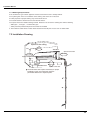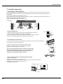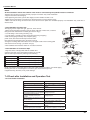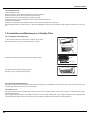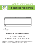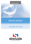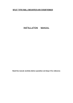
1
Installation Manual
7. Installation Manual
7.1 Notices for Installation
Caution
1.The unit should be installed only by authorized service center according to local or government regulations and in compliance with
this manual.
2.Before installing, please contact with local authorized maintenance center. If the unit is not installed by the authorized service center,
the malfunction may not be solved due to incovenient contact between the user and the service personnel.
3.When removing the unit to the other place, please firstly contact with the local authorized service center.
4.Warning: Before obtaining access to terminals, all supply circuits must be disconnected.
5.For appliances with type Y attachment, the instructions shall contain the substance of the following. If the supply cord is damaged, it
must be replaced by the manufacturer, its service agent or similarly qualified persons in order to avoid a hazard.
6.The appliance must be positioned so that the plug is accessible.
7.The temperature of refrigerant line will be high; please keep the interconnection cable away from the copper tube.
8.The instructions shall state the substance of the following:
This appliance is not intended for use by persons(including children)with reduced physical, sensory or mental capabilities, or lack
of experience and knowledge, unless they have been given supervision or instruction concerning use of the appliance by a person
responsible for their safety.
Children should be supervised to ensure that they do not play with the appliance.
7.1.1 Installation Site Instructions
Proper installation site is vital for correct and efficient operation of the unit. Avoid the following sites where:
●strong heat sources, vapours, flammable gas or volatile liquids are emitted.
●high-frequency electro-magnetic waves are generated by radio equipment, welders and medical equipment.
●salt-laden air prevails (such as close to coastal areas).
●the air is contaminated with industrial vapours and oils.
●the air contains sulphures gas such as in hot spring zones.
●corrosion or poor air quality exists.
7.1.2 Installation Site of Indoor Unit
1.The air inlet and outlet should be away from the obstructions. Ensure the air can be blown through the whole room.
2.Select a site where the condensate can be easily drained out, and where it is easily connected to outdoor unit.
3.Select a place where it is out of reach of children.
4.Select a place where the wall is strong enough to withstand the full weight and vibration of the unit.
5.Be sure to leave enough space to allow access for routine maintenance. The installation site should be 250cm or more above the
floor.
6.Select a place about 1m or more away from TV set or any other electric appliance.
7.Select a place where the filter can be easily taken out.
8.Make sure that the indoor unit is installed in accordance with installation dimension instructions.
9.Do not use the unit in the laundry or by swimming pool etc.
7.1.3 Safety Precautions for Electric Appliances
1.A dedicated power supply circuit should be used in accordance with local electrical safety regulations.
,
2.Don t drag the power cord with excessive force.
3.The unit should be reliably earthed and connected to an exclusive earth device by the professionals.
4.The air switch must have the functions of magnetic tripping and heat tripping to prevent short circuit and overload.
5.The minimum distance between the unit and combustive surface is 1.5m.
6.The appliance shall be installed in accordance with national wiring regulations.
7.An all-pole disconnection switch with a contact separation of at least 3mm in all poles should be connected in fixed wiring.
Note:
●Make sure the live wire, neutral wire and earth wire in the family power socket are properly
connected. There should be reliable circuit in the diagram.
●Inadequate or incorrect electrical connections may cause electric shock or fire.
18
Installation Manual
7.1.4 Earthing Requirements
1.Air conditioner is type I electric appliance. Please ensure that the unit is reliably earthed.
2.The yellow-green wire in air conditioner is the earthing wire which can not be used
for other purposes. Improper earthing may cause electric shock.
3.The earth resistance should accord to the national criterion.
4.The power must have reliable earthing terminal. Please do not connect the earthing wire with the following:
ķ Water pipe ĸ Gas pipe Ĺ Contamination pipe
ĺ Other place that professional personnel consider is unreliable
5. The model and rated values of fuses should accord with the silk print on fuse cover or related PCB.
7.2 Installation Drawing
Space to the ceiling
15cm
Above
Space to the wall
15cm Above
15cm Above
Space to the wall
300cm
Above
250cm
Above
Air outlet side
Space to the floor
The dimensions of the space necessary for proper
installation of the unit include the minimum
permissible distances to adjacent parts.
19
Installation Manual
7.3 Install Indoor Unit
7.3.1 Installation of Mounting Plate
1. Mounting plate should be installed horizontally. As the water tray's outlet for the indoor unit is two-way
type, during installation, the indoor unit should slightly slant to water tray's outlet for smooth drainage of
condensate.
2.Fix the mounting plate on the wall with screws.
3.Be sure that the mounting plate has been fixed firmly enough to withstand about 60 kg. Meanwhile, the
weight should be evenly shared by each screw.
(Note: the wall hole for 18K unit is Φ 65mm.)
Wall
09K UNIT:
Wall
Wall
Above
150 from
the wall
Above
150 from
the wall
Φ55
Φ55
Left
Right
7.3.2 Drill Piping Hole
Indoor
Outdoor
Wall pipe
1. Make the piping hole (Ф55) in the wall at a slight downward slant to the
outdoor side. (Note: the wall hole for 18K unit is Φ 65mm.)
2. Insert the piping-hole sleeve into the hole to prevent the connection piping
and wiring from being damaged when passing through the hole.
Seal pad
Φ55
7.3.3 Installation of Drain Hose
1.Connect the drain hose to the outlet pipe of the indoor unit. Bind the joint with rubber belt.
2.Put the drain hose into insulating tube.
outlet pipe of
indoor unit
drain hose
outlet pipe of
indoor unit
3.Wrap the insulating tube with wide rubber belt to prevent
the shift of insulating tube. Slant the drain hose downward
slightly for smooth drainage of condensate.
rubber belt
outlet pipe of
indoor unit
drain hose
rubber belt insulating tube
Note: The insulating tube should be connected reliably with
the sleeve outside the outlet pipe. The drain hose should be
slanted downward slightly, without distortion, bulge or
fluctuation. Do not put the outlet in the water.
rubber belt
outlet pipe of
indoor unit
connected
bulge
Flooded
7.3.4 Connecting Indoor and Outdoor Electric Wires
1.Open the front panel.
2.Remove the wiring cover as shown in Fig 6.
3.Make the power connection cord pass through the hole at the back of indoor unit.
4.Reinstall the cord anchorage and wiring cover.
5.Reinstall the front panel.
Wiring Cover
N(1)
blue
2
black brown
3
yellowgreen
outdoor unit connection
Fig.6
20
insulating tube
distortion
Installation Manual
NOTE:
All wires between indoor and outdoor units must be connected by the qualified electric contractor.
● Electric wires must be connected correctly. Improper connection may cause malfunction.
● Tighten the terminal screws tightly.
● After tightening the screws, pull the wire sligltly to confirm whether it's firm or not.
● Make sure that the electric connections are earthed properly to prevent electric shock.
● Make sure that all wiring connections are secure and the cover plates are reinstalled properly. Poor installation may cause fire or
electric shock.
7.3.5 Installation of Indoor Unit
Gas side pipe
●The piping can be output from right, right rear, left or left rear.
1.When routing the piping and wiring from the left or right side of indoor unit, cut off the
tailings from the chassis when necessary(As shown in Fig.7)
Ł Cut off tailing 1 when routing the wiring only;
ł Cut off tailing 1 and tailing 2 when routing both the wiring and piping.
2.Take out the piping from body case; wrap the piping,
power cords, drain hose with the tape and then make
them pass through the piping hole. (As shown in Fig.8)
3.Hang the mounting slots of the indoor unit on the upper hooks of the mounting plate
and check if it is firm enough. (As shown in Fig.9)
4.The installation site should be 250cm or more above the floor.
Tailing 2
Tailing 1
Fig.7
External connection
electric wire
Liquid side piping
Gas side piping
insulation
Liquid side
Piping insulation
Finally wrap it
Water drainage pipe
with tape
Left
Left rear
Right
Right rear
Fixing hook
Mounting
plate
Fig.8
Mounting
plate
Fig.9
7.3.6 Installation of Connection Pipe
1.Align the center of the pipe flare with the related valve.
2.Screw in the flare nut by hand and then tighten the nut with
spanner and torque wrench by referring to the following:
Tube diameter
Tightening torque,approximate(N·m)
Ф6.35(1/4”)
14̚18N·m(140-180kgf.cm)
Ф9.52(3/8”)
34̚42N·m(340-420kgf.cm)
Ф12.7(1/2”)
49̚61N·m(490-610kgf.cm)
Ф15.88(5/8”)
68̚82N·m(680-820kgf.cm)
Indoor unit piping
Spanner
Taper nut Piping
Torque
wrench
NOTE: Connect the connection pipe to indoor unit at first and then to outdoor unit. Handle piping
bending with care. Do not damage the connection pipe. Ensure that the joint nut
is tightened firmly, otherwise, it may cause leakage.
7.4 Check after Installation and Operation Test
7.4.1 Check after Installation
Items to be checked
Possible malfunction
Has it been fixed firmly?
The unit may drop, shake or emit noise.
Have you done the refrigerant leakage
test?
It may cause insufficient cooling(heating)
capacity
Is heat insulation sufficient?
It may cause condensation and dripping.
Is water drainage satisfactory?
It may cause condensation and dripping.
Is the voltage in accordance with the
rated voltage marked on the nameplate?
Is the electric wiring and piping
connection installed correctly and
securely?
Has the unit been connected to a secure
earth connection?
It may cause electric malfunctionor
damage the product.
Is the power cord specified?
Are the inlet and outlet openings
blocked?
Is the length of connection pipes and
refrigerant capacity been recorded?
It may cause electric malfunction or
damage the part.
It may cause electrical leakage.
It may cause electric malfunctionor
damage the part.
It may cause insufficient cooling(heating)
capacity.
The refrigerant capacity is not accurate.
21
Installation Manual
7.4.2 Operation Test
1.Before Operation Test
(1)Do not switch on power before installation is finished completely.
(2)Electric wiring must be connected correctly and securely.
(3)Cut-off valves of the connection pipes should be opened.
(4)All the impurities such as scraps and thrums must be cleared from the unit.
2.Operation Test Method
(1)Switch on power and press "ON/OFF"?button on the remote controller to start operation.
(2)Press MODE button to select the COOL, HEAT (Not available for cooling only unit), FAN to check whether the operation is normal or
not.
7.5 Installation and Maintenance of Healthy Filter
7.5.1 Installation of Healthy Filter
1.Lift up the front panel from its two ends, as shown by the arrow
direction, and then remove the air filter.(as shown in Fig.a)
Fig. a
Fig. b
2.Attach the healthy filter onto the air filter,(as shown in Fig.b).
Air filter
Healthy filter
3.Install the air filter properly along the arrow
direction in Fig.c, and then close the panel .
Fig.
c
7.5.2 Cleaning and Maintenance
Remove the healthy filter and reinstall it after cleaning according to the installation instruction. Don't use brush or hard things to clean
the filter. After cleaning, be sure to dry it in the shade.
7.5.3 Service Life
The general serive life for the healthy filter is about one year under normal condition. As for silver ion filter, it is invalid when its surface
becomes black (green).
●This supplementary instruction is provided for reference to the unit with healthy filter. If the graphics provided herein is different from
the actual product, please refer to the atual product. The quantity of healthy filters is based on the actual delivery.
22