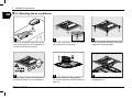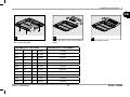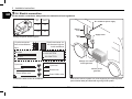
1
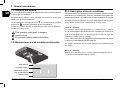
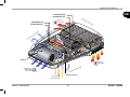
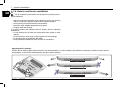
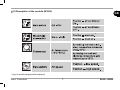
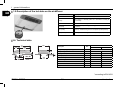
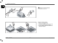
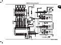
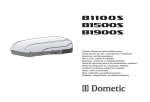
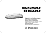
Operation, maintenance and installation manual
Libretto istruzioni per l’uso, la manutenzione e l’installazione
Betriebs-, Wartungs- und Installationsanleitung
Manuel d’utilisation, d’entretien et d’installation
Bedienings-, onderhouds- en installatiehandleiding
Manual de instrucciones para el uso, mantenimiento e instalación
Manual de instruções de uso, manutenção e instalação
Handbok för användning, underhåll och installation
Käyttö-, huolto- ja asennusohje
Bruks- vedlikeholds- og installasjonsanvisning
Betjenings-, vedligeholdelses- og installationsvejledning
©DOMETIC - 2007 All rights reserved - Printed in Italy
No part of this publication may be reproduced, copied or transmitted in any
form or by any means without prior written permission from DOMETIC.
Figures, descriptions, references and technical data in this manual are given
as mere example and are not binding.
In pursuing a policy of continual product and safety improvement, DOMETIC
reserves the right to make changes at any time without undertaking to give
prior notice or to update this manual every time.
Keep this document for future reference.
Warranty Validity
‘The product is warranted in accordance with the enforced Law and regulations implementing the Directive
1999/44/EC.
The Manufacturer s warranty does not extend to Product failures, defects or damage arising from and/or attributable to a wrong installation.
The Consumer is entitled to let the Product be installed by an authorised dealer, not bound by Dometic.
Index
1
General informations
1.1.
1.2.
1.3.
1.4.
1.5.
1.6.
1.7.
Scope of the manual.............................................4
Manufacturer and air conditioner data plate......4
Description of the air conditioner..........................4
How to use the air conditioner....................................6
Description of the controls................................... 7
Technical data................................................ 10
Ordinary maintenance....................................11
2
Installation instructions
2.1.
2.2.
2.3.
2.4.
Packaging, unpacking and handling..............12
Preparing the roof opening........................13
Mounting the air conditioner...........................16
Electric connection......................................18
3
Troubleshooting, maintenance, recycling
3.1.
3.2.
3.3.
Troubles, causes, solutions..............................19
Extraordinary maintenance..............................19
Recycling......................................................19
B1600 wiring diagram ..................................20
B2200 wiring diagram ..................................21
Spare part list B1600 - B2200............................22
Operation, Maintenance and
Installation manual
Air conditioner
Libretto istruzioni per l’uso, la manutenzione e
l’installazione
Condizionatore
GB
I
Bedienungs- und
Wartungsanleitung
Klimaanlage
D
Mise en route, entretien et
installation
Climatiseur
F
Handleiding voor bediening,
onderhoud en installatie
Airconditioner
NL
Manual de instrucciones para el uso, la manutención
y la instalación
Acondicionator
E
Livrete de instruções para uso, manutenção
e instalação
Aparelho de ar condicionado
P
Handbok för drift, underhåll och
installation
Luftkonditionering
S
Käyttö-, huolto- ja
asennusohje
Ilmastointilaite
Brukerveiledning og manual
til vedlikehold og installasjon
Airconditioner
Brugervejledning og manual
til vedligeholdelse og installation
Airconditioner
FIN
N
DK
1 General informations
1.1. Scope of the manual
GB
1.3. Description of the air conditioner
This manual has been made by the Manufacturer and it shall be regarded
as part of the air conditioner.
The information it contains, when complied with, ensures a correct and
efficient use of the air conditioner.
This air conditioner has been designed and manufactured to be installed
onto vehicles (i.e. camping-cars, caravans, motorhomes) to improve the
temperature conditions. It supplies fresh and dehumidified air in summer
and warm air in winter without, in any case, replacing the heating system
of the vehicle. In both cases, temperature is set by the user.
The first part of this manual is for users , the second one for qualified
technicians
facing the installation of the air conditioner.
To draw the readers attention to special parts of the text, the following
symbols have been used:
Fresh air - Running
The system is inclusive of: compressor ( a ), condenser ( b ), evaporator ( d ) and refrigerant gas under pressure. According to the physical
state of the refrigerant gas -i.e. liquid or gaseous, it heats or cools the
components where it passes through.
Fan ( c ) forces the internal air through the cooled evaporator from where
it comes out cooled down and dehumidified.
This action, protracted over the time, reduces the temperature into
the vehicle.
This operation may result in dangers
Useful advice
Environment safety related information
1.2. Manufacturer and air conditioner data plate
Warm air - Running
Ambient air is forced by fan ( c ) into an electrical heating resistance
( e ) and then recirculated inside the vehicle.
Manufacturer
Conformity marking
Model/Serial number
Year of manufacture
Technical data
B1600 - B2200
4
users ‘ instructions
general informations
1
GB
Condenser (b)
Compressor (a)
Air
Resistance (e)
Evaporator (d)
dra
wn
warm air
discharged
in
fro
m
ou
tsi
de
de
tsi
rom
ou
nf
ni
Air
w
dra
Fan (c)
warm air
discharged
sid
conditioned air
drawn inside
the vehicle
Air
wn
dra
rom
in f
out
e
condensate draining
air recirculated
inside the vehicle
users ‘ instructions
5
B1600 - B2200
1 general informations
GB
1.4. How to use the air conditioner
The air conditioner performance can be improved by taking some
simple measures.
• Improve the thermal insulation of the vehicle by closing any opening
and by covering any glassed surfaces with reflecting curtains.
• Avoid opening doors and windows unnecessarily.
• Select the most suitable temperature and speed.
• Properly direct the air flaps.
To prevent troubles and minimise risks for people, take the following
precautions:
• Do not obstruct the air inlets and outlets with cloths, paper or other
objects;
• Do not introduce your hands or other objects into the openings;
• Do not spray the air conditioner with water;
• Keep flammable substances away from the air conditioner.
Adjusting the air direction
Position the air diffusing flaps to direct the air to the desired position. In order to balance the airflow it’s necessary to rotate the center knob in
anticlockwise, to choose the wished position and then rotate clockwise.
B1600 - B2200
6
users ‘ instructions
1.5.Description of the controls (B1600)
GB
*
* (only for models equipped with resistance)
users ‘ instructions
7
B1600 - B2200
1 general informations
GB
1.5.Description of the controls (B2200)
BUTTON DESCRIPTION
Remote control (B2200)
REMOTE CONTROL
ON/OFF
F°/C°
Operation Mode
Display Window
F°/C°
Low Battery
LIGHT
Room
Temperature
Clock Display
Set Point
LIGHT**
¡$
Fan Speed Display
ROOM
UP (+)
Down (-)
Clock
ROOM
ON/OFF
Choose the temperature measurement unit between
Celsius (°C) or Fahrenheit (°F).
If temperature is displayed this function is enabled.
Pressing the light key the light on the airconditioner
diffuser is switched on (if equipped) .The light button
works also when the remote control is off.
Pressing this button the room symbol is displayed
and the local temperature is displayed instead the
set point. Pressing the Room button an other time
the Room symbol disappear and the set point temperature is displayed instead the local one.
This button works also when the remote control is off.
Fan
+
-
F°/C°
Mode
MODE
CLOCK
CLOCK
CLOCK
F°/C°
Light
TIMER
LIGHT
Set
ROOM
Pressing the “CLOCK” button for a time longer than
2 seconds, it is possible to modify the “TIME SETTING”, managing the UP (+) button or the DOWN
(-). Press the “SET” button to confirm the modifications. After 15 seconds the new set is confirmed in
any cases.
SLEEP
SET
SET
Room
Press the ON/OFF button to start the airconditioner.
When it’s OFF all the symbols are OFF, except the
clock and you can use the ROOM and the LIGHT
buttons.
I FEEL
SET
This button has two functions:
1) To confirm the TIME SETTING
2) To resend the actual operating setting
Reset Button
The RESET button erases all the configuration parameters to
default.
* (only for models equipped with resistance) - **(only for models equipped with light)
B1600 - B2200
8
users ‘ instructions
general informations
AUTOMATIC MODE
FAN MODE
GB
Press the MODE button.
Press the MODE button.
MODE
MODE
Set to “AUTO”
+
-
¡$
1
Set to “FAN”
Choose the Fan Speed
Choose the Set Point
You can use the LIGHT** and ROOM button.
(16°C - 31°C)
AUTO
In this mode the fan button is disabled.
You can use the LIGHT** and ROOM button.
Available Fan speeds (Cool/Heat*/Fan Mode)
COOL / HEAT MODE
30%%$
30%%$
30%%$
Press the MODE button.
Low battery
MODE
Set to “COOL” or “HEAT”*
¡$
¡$
+
-
Choose the Set Point
BATTERY COMPARTMENT
ON BACK SIDE OF REMOTE
CONTROL
J1 J2 J3 J4
(16°C - 31°C)
OFF
Choose the Fan Speed
30%%$
The low battery symbol will
appear in the display window
when the low battery condition
exists.
In this case after each
command, the “low voltage
symbol” flickers for 2 seconds.
In these 2 seconds the remote
control is not able to send other
commands.
You can use the LIGHT** and ROOM
Replace the batteries
2x1.5V AAA
* (only for models equipped with resistance) - **(only for models equipped with light)
users ‘ instructions
9
B1600 - B2200
1 general informations
GB
1.5.Description of the led state on the airdiffuser
LED State
Description
Off
Airconditioner off
Orange
Airconditioner on StandBy (switch ON - aiconditioner is waiting for
a command)
Green
Airconditioner is running
Red (fixed)
Anomaly - 230V power supply missing (12V
is present)
Red (1 flick)
Anomaly - Malfunctioning of the E1 temperature probe (internal)
Red (2 flicks)
Anomaly - Malfunctioning of the E2 temperature probe (external)
LED
1.6. Technical data
650
Description
310
Model
Unit
B1600
Refrigerant gas (type/quantity)
235
min 30
Refrigerating yield
B2200
see data plate
Watt/h
1500*
Cooling consumption
W
650
910
Heating capacity
W
800
1200
Electrical rating
V-Hz
230-50
230-50
IP
X4
X4
m3/h
310
380
Max internal volume of the vehicle (insulated walls)
m3
20
25
Weight
Kg
30
34
Protection degree
Conditioned air volume
2050*
* according to EN 14511
B1600 - B2200
10
users ‘ instructions
general informations
1
1.7. Ordinary maintenance
GB
Petrol
Cleaning; periodically clean the air conditioner and remove dust with a dump cloth. When
necessary, use a mild detergent. Do not use petrol or solvents.
Checks; regularly check the air conditioner and make sure that the water
outlet holes are not clogged.
Filters cleaning (1): periodically carry out this operation; wash the filters with a detergent solution and allow to dry before refitting.
Active carbon filter (2): It’s recomended to change the active carbon filters every year.
users ‘ instructions
11
B1600 - B2200
2 Installation instructions
GB
The air conditioner must be installed by skilled technicians. In addition to this requirement, the people making the unit installation must make sure
that the working conditions are safe for everybody concerned.
2.1. Packaging, unpacking and handling
Always follow the instructions printed on the packaging.
Remove the air conditioner from its packaging and made sure that
it is not damaged.
Never use the rear air openings to lift the air conditioner
from its packaging
Move the air conditioner to the installation site under safe conditions.
B1600 - B2200
12
users ‘ instructions
Installation instructions 2
2.2. Preparing the roof opening
GB
According to the vehicle dimensions and depending on the air
conditioning needs, one or more units can be installed. The air
conditioner must be installed right in the middle with respect to the
vehicle Width and length.
Before installing the unit, make sure that the opening does not
interfere with the existing furnishing (lamps, wardrobes, doors,
curtains, etc.). This check allows for an easy mounting of the air
conditioner and a troublefree air circulation.
To install the air conditioner, the roof shall have an opening of suitable sizes. It is possible to use an existing air inlet or make a new
one.
contact the vehicle manufacturer and make sure that the
roof structure can tolerate the static load and the stress transmitted vehicle, especially under running conditions. Sometimes vehicle manufacturers previously arrange areas for the
unit installation weakening and/or electric cable from being
cut.
The air conditioner should preferably be installed on a
level plane. Maximum allowed inclination: 10°.
users ‘ instructions
13
B1600 - B2200
2 Installation instructions
GB
Danger of electrical hazards.
Turn all power sources off
Using an existing opening
1. Remove the skylight cover.
2. Clean the installation opening all around
by removing any adhesive residues.
3. Fill any existing screw hole or deformation
with filler or silicone.
B1600 - B2200
14
users ‘ instructions
Installation instructions
2
GB
New installation opening
1. Using the printed cardboard template supplied with the unit, find the position and dimensions of the new opening.
2. Drill the four corners.
3. Cut by joining the previously made holes.
4. If necessary, mount a reinforcing wooden
frame.
Drill a hole for the
supply cables
users ‘ instructions
15
B1600 - B2200
2 Installation instructions
GB
2.3. Mounting the air conditioner
Set the air conditioner onto the roof opening. Never slide the air conditioner on
the roof, but lift when moving it.
Note: the conical pins under the base
must enter the roof openings.
Fix the air diffuser brackets to the base
using the 4 screws provided.
Always tighten to the recommended torque wrench setting. Do not overtighten!
Mount the airdiffuser linking gaskets.
For correct thickness follow the table on
page 19.
Do the electrical connection as described
in paragraph 2.4.
B1600 - B2200
16
users ‘ instructions
Installation instructions
2
GB
Fix the cooling unit to the brackets using
the 4 screws provided.
THICKNESS OF THE ROOF
Mount the filters in the order shown in
figure.
THICKNESS OF THE GASKET
to
30 mm
10 mm
from
30
to
35 mm
15 mm
from
35
to
40 mm
20 mm
from
40
to
45 mm
25 mm
from
45
to
50 mm
30 mm
from
50
to
55 mm
35 mm
from
55
to
60 mm
40 mm
from
60
to
65 mm
45 mm
from
65
to
70 mm
50 mm
from
70
to
75 mm
55 mm
from
75
to
80 mm
60 mm
users ‘ instructions
Mount the filters covers.
17
B1600 - B2200
2 Installation instructions
GB
2.4. Electric connection
For the electric connections, always follow the national and local regulations
Length
L
Crosssection
(m)
(mm2)
< 7,5
1,5
Air conditioner power supply
Various
users
2,5
> 7,5
1
12-pole connector on
the electronic device
inside airdiffuser
12-pole connector
from airconditioner
base
Red wire
Supply mains
Fuse
box
Arrange a specific electric system
12V DC
+ POLE BATTERY
Black wire
- POLE BATTERY
B2200
Changeover switch
mains/generator
230V 50Hz
Cyan wire
Brown wire
Green-Yellow wire
2
Cyan wire
Electric power
generator
Brown wire
Green-Yellow wire
3
Connect the wires to the air conditioner.
B1600 - B2200
Connect the electric system to a circuit supplying the required power
(see technical data) and fitted with a good ground system.
18
users ‘ instructions
Troubleshooting, maintenance, recycling 3
defective thermal protection
defective capacitor
low power supply (less than 200V)
no power supply
damaged sealing gasket
water outlet holes are clogged
defective external fan
air filter is clogged
defective internal fan
thermal exchange batteries are dirty
damaged compressor
refrigerant gas is not enough
defective heating resistance
switch wrongly positioned
defective thermal protection
check the set point temperature
GB
temperature over 40°C
Operations to be carried out
by authorised personnel
temperature less than 18°C
Operations to be carried
out by the user
SOLUTION
3.1. Troubles, causes, solutions
CAUSA
the air conditioner does not cool sufficiently
the air conditioner does not heat enough
no air circulation into the vehicle
water leaks into the vehicle
the air conditioner does not start
the air conditioner stops running
3.2. Extraordinary maintenance
3.3. Recycling
For the best performance of your air conditioner, have your dealer/workshop clean it thoroughly before use:
1. thermal exchange batteries
2. water outlet holes are properly cleaned.
users ‘ instructions
Regarding disposal and recycling, follow the national or local
regulations. To this end, address to the authorised environment
bodies.
19
B1600 - B2200
B1600 wiring diagram
GB
Rev.2
B1600 - B2200
20
LED
BOARD
LED
BOARD
LED
BOARD
LED
BOARD
B2200 wiring diagram
GB
21
B1600 - B2200
Spare part list B1600 - B2200
GB
49
2
36
50
48
28 21
51
46
4
59
43
38
47
37
31
22
52
12
10
32
42
39
25
34
7
17
18
11
19
41
8
16
44
40
B2200
6
33
35
45
53
9
55
30 29 24 23
49
27
46
4
50
48
54
13
26
15
56 57
3
38
47
37
52
1
14
58
45
53
20
42
39
5
40
41
B1600
B1600 - B2200
22
Spare part list B1600 - B2200
GB
N.
DESCRPTION
N.
DESCRPTION
N.
DESCRPTION
1
PAN BASE
24
CAPACITOR
47
GASKET
2
COVER
25
PLENUM
48
GASKET
3
RIVETS TWO STAGE
26
FAN SUPPORT
49
GASKET
4
INSULATOR
27
FAN
50
SCREW
5
GASKET
28
RELAY BOARD
51
LABEL
6
INSERTS
29
CAPACITOR
52
ACTIV CARBON FILTER
7
SUPPORT
30
CAPACITOR
53
FILTER
8
SUPPORT
31
CONDENSER
54
WIRING
9
COMPRESSOR
32
PIPE
55
WIRING
10
CAPACITOR
33
PIPE
56
SWITCH
11
VIBRATION DAMPER
34
FILTER KIT
57
THERMOSTAT
12
COMPRESSOR WIRING
35
GASKET
58
KNOB
13
EVAPORATOR
36
HEAT INSULATOR BOX
59
EMC FILTER
14
GASKET
37
AIR DIFFUSER BASE
15
FAN
38
AIR DIFFUSING FLAP
16
RESISTOR
39
GRILLE
17
BUSHING
40
DEFLECTOR SLIDE
18
SPRING
41
KNOB
19
THERMAL SWITCH
42
COVER
20
OR GASKET
43
RECEIVER BOARD
21
VELCRO
44
RECEIVER COVER
22
LABEL
45
LABEL
23
CAPACITOR
46
FIXING BRACKET
23
B1600 - B2200