1
Solution Ultima 844/862/880
Installation Manual
ISSUE 1.20
MA48XI
Solution
This page has been included for you to cut out and insert into the
spine
of the folder
Ultima
844
/862
/880
Installation
Manual
ISSUE 1.20
(61-2) 9672 1233
Solution Ultima 844/862/880
Installation Manual
Copyright 1998 by Electronics Design and Manufacturing Pty Limited,
SYDNEY, AUSTRALIA
Document Part Number MA48XI
DOCUMENT ISSUE 1.20
Printed 16 February 1999
This documentation is provided to suit Solution Ultima 844/862/880 Control Panel
(CC484/CC486/CC488)
Firmware Revision 1.00
Hardware Revision A - J
Alarm Link required = 2.72 or higher
Control Panel Software Version 1.00 = S844_V10
= S862_V10
= S880_V10
Copyright Notice
All rights reserved. No part of this publication may be reproduced, sent or stored in a retrieval system in any form or by any
means, electronic, mechanical, photocopying, recording, or otherwise, without the prior written permission of Electronics
Design and Manufacturing Pty Limited.
Trademarks
Throughout this document trademark names may have been used. Rather than put a trademark symbol in every occurrence
of a trademark name, we state that we are using the names only in an editorial fashion and to the benefit of the trademark
owner with no intention of infringement of the trademark.
Notice of Liability
While every precaution has been taken in the preparation of this document, neither Electronics Design and Manufacturing
Pty Limited nor any of its official representatives shall have any liability to any person or entity with respect to any
liability, loss or damage caused or alleged to be caused directly or indirectly by the information contained in this book.
Electronics Design and Manufacturing Pty Limited reserves the right to make changes to features and specifications at any
time without prior notification in the interest of ongoing product development and improvement.
Table Of Contents
Introduction______________________________________________________________________17
Introduction __________________________________________________________________________ 18
Solution Ultima 844 Features ____________________________________________________________ 19
Solution Ultima 862 Features ____________________________________________________________ 20
Solution Ultima 880 Features ____________________________________________________________ 21
Quick Start ___________________________________________________________________________ 22
Solution Ultima 844 Zone Defaults ________________________________________________________________24
Solution Ultima 862 Zone Defaults ________________________________________________________________24
Solution Ultima 880 Zone Defaults ________________________________________________________________24
Zone Types___________________________________________________________________________________25
Codepad Indicators ________________________________________________________________27
CP5 Eight Zone LED Codepad __________________________________________________________ 28
Zone Indicators _______________________________________________________________________________28
AWAY Indicator ______________________________________________________________________________28
STAY Indicator _______________________________________________________________________________29
MAINS Indicator ______________________________________________________________________________29
FAULT Indicator ______________________________________________________________________________29
Audible Indicators _____________________________________________________________________________30
CP5 Eight Zone LCD Codepad __________________________________________________________ 31
Zone Indicators _______________________________________________________________________________31
AWAY Indicator ______________________________________________________________________________31
STAY Indicator _______________________________________________________________________________32
System Disarmed ______________________________________________________________________________32
MAINS Indicator ______________________________________________________________________________32
FAULT Indicator ______________________________________________________________________________33
Programming Mode ____________________________________________________________________________33
Off Indicator/Zone Sealed _______________________________________________________________________33
On Indicator/Zone In Alarm _____________________________________________________________________33
Audible Indicators _____________________________________________________________________________34
CP5 Master Partitioned LED Codepad____________________________________________________ 35
Zone Indicators _______________________________________________________________________________35
Area On/Off Indicators _________________________________________________________________________35
Area Display Indicators _________________________________________________________________________36
Status Indicators_______________________________________________________________________________36
PARTIAL Indicator __________________________________________________________________________36
AUX Indicator ______________________________________________________________________________36
MAINS Indicator ____________________________________________________________________________37
FAULT Indicator ____________________________________________________________________________37
Audible Indicators ___________________________________________________________________________37
System Operations_________________________________________________________________39
System Operations_____________________________________________________________________ 40
Arming The System In AWAY Mode ______________________________________________________________40
Forced Arming______________________________________________________________________________40
Disarming The System From AWAY Mode _________________________________________________________41
Arming The System In STAY Mode 1 _____________________________________________________________42
Entry Guard Timer For STAY Mode_____________________________________________________________42
Forced Arming______________________________________________________________________________43
Disarming The System From STAY Mode 1_________________________________________________________44
Arming The System In STAY Mode 2 _____________________________________________________________45
Entry Guard Timer For STAY Mode_____________________________________________________________45
Forced Arming______________________________________________________________________________45
Disarming The System From STAY Mode 2_________________________________________________________46
Codepad Duress Alarm _________________________________________________________________________47
Codepad Panic Alarm __________________________________________________________________________47
Codepad Fire Alarm____________________________________________________________________________47
Codepad Medical Alarm ________________________________________________________________________47
Isolating Zones ________________________________________________________________________ 48
Standard Isolating ___________________________________________________________________________49
Code To Isolate _____________________________________________________________________________50
Fault Analysis Mode____________________________________________________________________ 51
Fault Descriptions______________________________________________________________________ 53
System Fault _________________________________________________________________________________53
Low Battery ________________________________________________________________________________53
Date and Time ______________________________________________________________________________53
RF Receiver Fail ____________________________________________________________________________53
Horn Speaker_______________________________________________________________________________53
Telephone Line Fail__________________________________________________________________________53
E2 Fault ___________________________________________________________________________________53
Fuse Fail __________________________________________________________________________________53
RF Low Battery _______________________________________________________________________________53
Tamper Fail __________________________________________________________________________________54
Sensor Watch Fault ____________________________________________________________________________54
RF Sensor Watch Fault _________________________________________________________________________54
Communication Fail ___________________________________________________________________________54
AC Mains Failure ___________________________________________________________________________54
Remote Radio Transmitter Operations ________________________________________________ 55
Remote Radio Transmitter Operations ____________________________________________________ 56
Indications Upon Remote Radio Transmitter Operations _______________________________________________57
Remote Radio User Code Priority Levels ___________________________________________________________57
Changing Or Deleting Remote Radio User Codes_____________________________________________________58
System Functions_________________________________________________________________ 61
System Functions ______________________________________________________________________ 62
Installer Code Functions ________________________________________________________________________62
Adding Or Deleting RF Wireless Devices_________________________________________________________63
Set The Number Of Days Until The First Test Report _______________________________________________65
Changing Domestic Phone Numbers_____________________________________________________________66
Change Telco Arm/Disarm Sequence ____________________________________________________________68
Setting STAY Mode 2 Zones __________________________________________________________________71
Satellite Siren Service Mode ___________________________________________________________________72
Turning Telephone Monitor Mode On/Off ________________________________________________________73
Walk Test Mode ____________________________________________________________________________74
Event Memory Recall Mode ___________________________________________________________________75
Master Code Functions _________________________________________________________________ 76
Arm or Disarm Both Areas At The Same Time ____________________________________________________76
Changing and Deleting User Codes______________________________________________________________77
Changing and Deleting Remote Radio User Codes__________________________________________________79
Changing Domestic Phone Numbers_____________________________________________________________81
Change Telco Arm/Disarm Sequence ____________________________________________________________83
Setting STAY Mode 2 Zones __________________________________________________________________86
Turning Outputs On/Off ______________________________________________________________________87
Setting The Date and Time ____________________________________________________________________89
Walk Test Mode ____________________________________________________________________________90
Event Memory Recall Mode ___________________________________________________________________91
User Code Functions ___________________________________________________________________ 92
Arm or Disarm Both Areas At The Same Time ____________________________________________________92
Hold Down Functions___________________________________________________________________ 93
Arm The System In AWAY Mode ______________________________________________________________93
Arm The System In STAY Mode 1______________________________________________________________93
Arm The System In STAY Mode 2______________________________________________________________94
Horn Speaker Test ___________________________________________________________________________94
Bell Test __________________________________________________________________________________94
Strobe Test_________________________________________________________________________________94
Turning Day Alarm On and Off ________________________________________________________________95
Fault Analysis Mode _________________________________________________________________________95
Initiate A Modem Call ________________________________________________________________________96
Reset Latching Outputs _______________________________________________________________________96
Codepad Buzzer Tone Change__________________________________________________________________97
Send Test Report ____________________________________________________________________________97
Remote System____________________________________________________________________99
Operations Via Telephone __________________________________________________________99
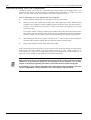
Remote Arming Via The Telephone _____________________________________________________ 100
Programming ___________________________________________________________________101
Programming ________________________________________________________________________ 102
Programming With The Remote Codepad ________________________________________________ 103
Programming With The Hand Held Programmer __________________________________________ 105
Programming With The Programming Key _______________________________________________ 106
Programming Option Bits _____________________________________________________________ 107
Installer’s Programming Commands ____________________________________________________ 107
Command 958 - Enable/Disable Zone Status Mode __________________________________________________108
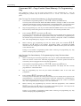
Command 959 - Test Programming Key ___________________________________________________________109
Command 960 - Exit Installer's Programming Mode__________________________________________________110
Command 961- Reset Control Panel Back To Factory Default Settings ___________________________________110
Command 962 - Copy Control Panel Memory To Programming Key_____________________________________111
Command 963 - Copy From Programming Key To Control Panel _______________________________________112
Command 964 - Erase Programming Key __________________________________________________________113
Command 965 - Set Up Domestic Dialling Format___________________________________________________114
Command 966 - Enable/Disable Automatic Stepping Of Locations ______________________________________115
Command 999 - Display Panel Type Or Software Version Number ______________________________________117
Disable Factory Default ________________________________________________________________________118
Defaulting The Control Panel ___________________________________________________________________119
Alarm Link Operations ____________________________________________________________121
Alarm Link Software _________________________________________________________________ 122
Remote Connect______________________________________________________________________________122
Remote Connect With Customer Control ________________________________________________________122
Remote Connect Without Call Back Verification __________________________________________________123
Remote Connect With Call Back Verification_____________________________________________________123
Direct Connect _____________________________________________________________________________123
Alarm Link Options___________________________________________________________________________124
Enable Upload/Download Via Alarm Link _______________________________________________________124
Enable Alarm Link Call Back _________________________________________________________________124
Terminate Alarm Link Connection On Alarm _____________________________________________________124
Use External Modem Module (CC811) For Alarm Link Operations____________________________________124
Domestic Dialling ________________________________________________________________125
Domestic Dialling Format ______________________________________________________________ 126
Domestic Dialling Function_____________________________________________________________________126
Acknowledge Domestic Dialling _______________________________________________________________126
Setting Up and Programming Domestic Reporting ___________________________________________________127
Disable Domestic Dialling____________________________________________________________________128
Dialler Reporting Formats _________________________________________________________129
Transmission Formats_________________________________________________________________ 130
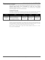
Contact ID Format ____________________________________________________________________________130
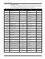
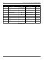
Point ID Codes_______________________________________________________________________________131
4+2 Reporting Format _________________________________________________________________________133
Basic Pager Reporting Format ___________________________________________________________________134
Basic Pager Display Information ________________________________________________________ 135
Subscriber ID Number _________________________________________________________________________135
Zone Status _________________________________________________________________________________135
System Status________________________________________________________________________________135
Dialler Information ______________________________________________________________ 137
Dialler Information____________________________________________________________________ 138
Primary Telephone Number For Receiver 1 ________________________________________________________139
Secondary Telephone Number For Receiver 1 ______________________________________________________139
Handshake Tone For Receiver 1 _________________________________________________________________140
Transmission Format For Receiver 1 _____________________________________________________________141
Subscriber ID Number For Receiver 1 ____________________________________________________________141
Primary Telephone Number For Receiver 2 ________________________________________________________142
Secondary Telephone Number For Receiver 2 ______________________________________________________142
Handshake Tone For Receiver 2 _________________________________________________________________143
Transmission Format For Receiver 2 _____________________________________________________________144
Subscriber ID Number For Receiver 2 ____________________________________________________________144
Dialling Format ______________________________________________________________________________145
Reserved ___________________________________________________________________________________145
Telco Arming Sequence _______________________________________________________________________146
Telco Arming – Call Forward Immediate On _____________________________________________________146
Telco Arming – Call Forward No Answer On ____________________________________________________146
Telco Disarming Sequence _____________________________________________________________________147
Telco Arming – Call Forward Immediate Off _____________________________________________________147
Telco Arming – Call Forward No Answer Off ____________________________________________________147
Call Back Telephone Number ___________________________________________________________________147
Ring Count _________________________________________________________________________________148
Answering Machine Bypass ____________________________________________________________________148
Telephone Line Fault Options ___________________________________________________________________149
Operate The FAULT Indicator When Telephone Line Fails__________________________________________149
Sound Speaker, Bell and Strobe When The System Is Armed ________________________________________149
Sound Speaker, Bell and Strobe When The System Is Disarmed ______________________________________149
Reserved _________________________________________________________________________________149
Dialler Options__________________________________________________________________ 151
Programming Option Bits ______________________________________________________________ 152
Dialler Options 1 _____________________________________________________________________________153
Enabled = Allow Dialler Reporting Functions ____________________________________________________153
Disabled = Disable All Dialler Reporting Functions________________________________________________153
Enable Remote Arming Via The Telephone ______________________________________________________153
Enable Answering Machine Bypass Only When Armed_____________________________________________153
Enabled = Use Bell 103 For FSK Format / Disabled = CCITT V21 Format______________________________153
Dialler Options 2 _____________________________________________________________________________154
Send Open/Close Reports Only If A Previous Alarm Has Occurred____________________________________154
Send Open/Close Reports When In STAY Mode 1 and STAY Mode 2 _________________________________154
Delay Siren Until Transmission Complete _______________________________________________________154
Extend Time To Wait For Handshake From 30 - 55 Seconds _________________________________________154
Dialler Options 3 _____________________________________________________________________________155
Set DTMF Dialling Pulses To 1 Digit/Second ____________________________________________________155
Reserved _________________________________________________________________________________155
Change Decadic Dialling To 60/40 _____________________________________________________________155
Reserved _________________________________________________________________________________155
Alarm Link Options___________________________________________________________________________156
Enable Upload/Download Via Alarm Link _______________________________________________________156
Enable Alarm Link Call Back _________________________________________________________________156
Terminate Alarm Link Connection On Alarm_____________________________________________________156
Use External Modem Module (CC811) For Alarm Link Operations ___________________________________156
User Codes _____________________________________________________________________ 157
Access Codes _________________________________________________________________________ 158
Installer Code _______________________________________________________________________________158
User Codes _________________________________________________________________________________159
Solution Ultima 844/862 User Codes _____________________________________________________________160
Solution Ultima 880 User Codes _________________________________________________________________160
User Code Priority ____________________________________________________________________________161
Arm and Disarm ___________________________________________________________________________161
Arm Only_________________________________________________________________________________161
Arm and Disarm + Open/Close Reports _________________________________________________________161
Arm Only + Closing Reports__________________________________________________________________161
Arm and Disarm + Code To Isolate _____________________________________________________________162
Arm and Disarm + Code To Isolate + Open/Close Reports___________________________________________162
Arm and Disarm + Master Code Functions _______________________________________________________162
Arm and Disarm + Master Code Functions + Open/Close Reports _____________________________________162
Arm and Disarm + Master Code Functions + Code To Isolate ________________________________________162
Arm and Disarm + Master Code Functions + Code To Isolate + Open/Close Reports ______________________162
Zone Information ________________________________________________________________163
Day Alarm Zones_____________________________________________________________________________164
Day Alarm Resetting ________________________________________________________________________164
Day Alarm Latching ________________________________________________________________________164
Day Alarm Operation__________________________________________________________________________165
EOL Resistor Value ___________________________________________________________________________166
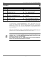
Connections Of Split EOL Resistors Using N/C Contacts______________________________________________167
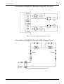
Connections Of Split EOL Resistors With Tamper Circuit _____________________________________________167
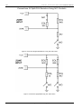
Connections Of Split EOL Resistors Using N/O Contacts _____________________________________________168
Zone Programming ___________________________________________________________________ 169
Zone Operating Information ____________________________________________________________________169
Zone Options ________________________________________________________________________________169
Zone Reporting Information ____________________________________________________________________169
Solution Ultima 844 Zones Defaults ______________________________________________________________170
Solution Ultima 862 Zones Defaults ______________________________________________________________170
Solution Ultima 880 Zones Defaults ______________________________________________________________170
Zone Types__________________________________________________________________________________171
Instant Zone _______________________________________________________________________________171
Handover Zone_____________________________________________________________________________171
Delay-1 Zone ______________________________________________________________________________171
Delay-2 Zone ______________________________________________________________________________171
Reserved__________________________________________________________________________________171
Reserved__________________________________________________________________________________172
24 Hour Medical ___________________________________________________________________________172
24 Hour Panic _____________________________________________________________________________172
24 Hour Hold-Up ___________________________________________________________________________172
24 Hour Tamper____________________________________________________________________________172
Reserved__________________________________________________________________________________172
Keyswitch Zone ____________________________________________________________________________172
24 Hour Burglary Zone ______________________________________________________________________172
24 Hour Fire Zone __________________________________________________________________________172
Chime Zone _______________________________________________________________________________173
Zone Not Used _____________________________________________________________________________173
Zone Pulse Count_____________________________________________________________________________173
Zone Pulse Count Handover __________________________________________________________________173
Zone Pulse Count Time ________________________________________________________________________174
Zone Options 1_______________________________________________________________________________175
Lockout Siren & Lockout Dialler ______________________________________________________________175
Delay Alarm Reporting ______________________________________________________________________175
Silent Alarm_______________________________________________________________________________176
Sensor Watch ______________________________________________________________________________176
Keyswitch Zone Options _______________________________________________________________________177
Latching Arm and Disarm In AWAY Mode ______________________________________________________177
Latching Arm In AWAY Mode ________________________________________________________________177
Latching Disarm From AWAY Mode, STAY Mode 1 Or STAY Mode 2 _______________________________177
Latching Arm and Disarm In STAY Mode 1______________________________________________________177
Latching Arm In STAY Mode 1 _______________________________________________________________177
Latching Disarm From STAY Mode 1 Or STAY Mode 2____________________________________________177
Momentary Arm and Disarm In AWAY Mode ____________________________________________________178
Momentary Arm In AWAY Mode______________________________________________________________178
Momentary Disarm From AWAY Mode, STAY Mode 1 Or STAY Mode 2 _____________________________178
Momentary Arm and Disarm In STAY Mode 1 ___________________________________________________178
Momentary Arm In STAY Mode 1 _____________________________________________________________178
Momentary Disarm From STAY Mode 1 Or STAY Mode 2 _________________________________________178
Zone Options 2_______________________________________________________________________________179
Isolate In STAY Mode 1 _____________________________________________________________________179
Zone Isolation Allowed ______________________________________________________________________179
Forced Arming Allowed _____________________________________________________________________179
Zone Restore Report ________________________________________________________________________179
Zone Reporting Information ____________________________________________________________________180
Zone Report Code __________________________________________________________________________180
Zone Dialler Options ________________________________________________________________________180
Swinger Shutdown Count For Siren ______________________________________________________________181
Swinger Shutdown Count For Dialler _____________________________________________________________182
System Reporting Information _____________________________________________________ 183
Reporting Information _________________________________________________________________ 184
Zone Status – Zone Tamper Report_______________________________________________________________184
Zone Status – Walk Test Report _________________________________________________________________184
Zone Status – Bypass Reports ___________________________________________________________________185
Zone Status – Trouble Reports __________________________________________________________________185
Zone Status – Sensor Watch Reports______________________________________________________________186
Zone Status – Alarm Restore Code _______________________________________________________________186
Zone Status Reporting Options __________________________________________________________________186
RF Supervision Time__________________________________________________________________________187
RF Low Battery Report ________________________________________________________________________187
RF Receiver Trouble Report ____________________________________________________________________188
RF Receiver Trouble Restore Report _____________________________________________________________188
RF Dialler Options ___________________________________________________________________________188
Open/Close Reports___________________________________________________________________________189
Open/Close Reporting Options __________________________________________________________________189
Codepad Duress Report________________________________________________________________________190
Codepad Panic Report _________________________________________________________________________190
Codepad Fire Report __________________________________________________________________________191
Codepad Medical Report_______________________________________________________________________191
Codepad Reporting Options ____________________________________________________________________192
System Status – Fuse Fail Report ________________________________________________________________192
System Status – Fuse Fail Restore Report__________________________________________________________192
System Status – AC Fail Report _________________________________________________________________193
System Status – AC Fail Restore Report___________________________________________________________193
System Status - Low Battery Report ______________________________________________________________194
System Status - Low Battery Restore Report _______________________________________________________194
System Status - Access Denied __________________________________________________________________195
Code Retries ______________________________________________________________________________195
System Status Reporting Options ________________________________________________________________196
Test Reporting Time __________________________________________________________________________197
Test Reporting Dialler Options __________________________________________________________________197
Programmable Outputs ___________________________________________________________ 199
Outputs _____________________________________________________________________________ 200
Output Defaults ______________________________________________________________________________200
Default For Strobe ____________________________________________________________________________200
Default For Entry/Exit_________________________________________________________________________200
Redirecting Outputs To The Codepad Buzzer_______________________________________________________201
Output Event Types ___________________________________________________________________________202
Output Polarity ______________________________________________________________________________211
Output Not Used ___________________________________________________________________________211
Normally Open, Going Low __________________________________________________________________211
Normally Open, Pulsing Low _________________________________________________________________211
Normally Open, One Shot Low ________________________________________________________________211
Normally Open, One Shot Low With Retrigger ___________________________________________________211
Normally Open, One Shot Low With Reset ______________________________________________________211
Normally Open, One Shot Low With Alarm______________________________________________________212
Normally Open, Latching Low ________________________________________________________________212
Normally Low, Going Open __________________________________________________________________212
Normally Low, Pulsing Open _________________________________________________________________212
Normally Low, One Shot Open________________________________________________________________212
Normally Low, One Shot Open With Retrigger ___________________________________________________212
Normally Low, One Shot Open With Reset ______________________________________________________212
Normally Low, One Shot Open With Alarm______________________________________________________212
Normally Low, Latching Open ________________________________________________________________212
Timing Of Outputs ___________________________________________________________________________213
Pulsing Polarities _____________________________________________________________________________213
One Shot Polarities ___________________________________________________________________________214
System Event Timers ______________________________________________________________215
System Event Timers__________________________________________________________________ 216
Programming Entry/Exit Timers _________________________________________________________________216
Entry Timer 1________________________________________________________________________________216
Entry Timer 2________________________________________________________________________________216
Exit Time ___________________________________________________________________________________217
Entry Guard Timer For STAY Mode______________________________________________________________217
Delay Alarm Reporting Time ___________________________________________________________________217
Sensor Watch Time ___________________________________________________________________________218
Codepad Lockout Time ________________________________________________________________________218
Siren Run Time ______________________________________________________________________________219
Siren Sound Rate _____________________________________________________________________________219
Auto Arming Pre-Alert Timer ___________________________________________________________________220
Auto Arming Time____________________________________________________________________________220
Auto Disarming Time _________________________________________________________________________221
Kiss-Off Wait Time ___________________________________________________________________________221
Speaker Beep Volume _________________________________________________________________________221
System Time ________________________________________________________________________________222
System Date _________________________________________________________________________________223
Setting The Date and Time ___________________________________________________________________223
System and Consumer Options______________________________________________________225
Programming Option Bits _____________________________________________________________ 226
System Options 1_____________________________________________________________________________227
Enable EDM Smart Lockout __________________________________________________________________227
Enable Monitoring Of Horn Speaker ____________________________________________________________227
Allow Strobe Indications For Radio Arm/Disarm __________________________________________________227
Assign Button 4 On Transmitter To Arm STAY Mode 1 ____________________________________________227
System Options 2_____________________________________________________________________________228
Enable Codepad Panic To Be Silent ____________________________________________________________228
Enable Codepad Fire To Be Silent______________________________________________________________228
Enable Codepad Medical To Be Silent __________________________________________________________228
Enable Access Denied To Be Silent ____________________________________________________________228
System Options 3_____________________________________________________________________________229
Enable AC Fail In 1 Hour ____________________________________________________________________229
Ignore AC Mains Fail Indication _______________________________________________________________229
Enable Zone Pulse Count Handover ____________________________________________________________229
Enable Handover Delay To Be Sequential________________________________________________________229
System Options 4_____________________________________________________________________________230
Enable Control Panel To Power Up In The Disarmed State __________________________________________230
Enable Arm/Disarm Tracking On Power Up ______________________________________________________230
Enable Internal Crystal To Keep Time __________________________________________________________230
Enable Radio Key/Keyswitch Interface / Night Arm Station Or RE005 _________________________________230
Consumer Options 1 __________________________________________________________________________231
Send Test Reports Only If The System Is Armed __________________________________________________231
Enable - Send Test Report After Siren Reset______________________________________________________231
Enable Auto Arm In STAY Mode 1 ____________________________________________________________231
Enable The STAY Indicator To Display Day Alarm Status __________________________________________231
Consumer Options 2 __________________________________________________________________________232
Enable Codepad Extinguish Mode______________________________________________________________232
Enable Single Button Arming In AWAY Mode, STAY Mode 1 and STAY Mode 2 _______________________232
Enable Single Button Disarming From STAY Mode 1 Or STAY Mode 2 _______________________________232
Enable Alarm Memory Reset On Disarm ________________________________________________________232
Consumer Options 3 __________________________________________________________________________233
Enable Codepad Fault Alarm Beeps ____________________________________________________________233
Use Digit 3 For Codepad Duress Instead Of Digit 9 ________________________________________________233
Enable Operation Of Siren & Strobe In STAY Mode 1 & STAY Mode 2 _______________________________233
Enable Zone Tamper Alarms To Be Silent _______________________________________________________233
Radio Input Options___________________________________________________________________________234
DS304 Mhz Receiver (RF3212) _______________________________________________________________234
Latching Keyswitch Input ____________________________________________________________________234
Momentary Keyswitch Input __________________________________________________________________234
Partitioning ____________________________________________________________________ 235
CP5 Master Partitioned LED Codepad ___________________________________________________ 236
Zone Indicators ______________________________________________________________________________236
Area On/Off Indicators ________________________________________________________________________237
Area Display Indicators________________________________________________________________________237
Status Indicators _____________________________________________________________________________237
PARTIAL Indicator_________________________________________________________________________237
AUX Indicator_____________________________________________________________________________238
MAINS Indicator___________________________________________________________________________238
FAULT Indicator___________________________________________________________________________238
Audible Indicators __________________________________________________________________________239
Operating Codepads In Partitioning _____________________________________________________ 240
Operating From A CP5 Area Addressable LED Codepad____________________________________________240
Operating From A CP5 Master Partitioned Codepad _______________________________________________240
Programming ________________________________________________________________________ 241
Partitioning Options 1 _________________________________________________________________________241
Enable First To Open/Last To Close Reporting ___________________________________________________241
Enable Main Codepad To Display Data Only For Area 1 ____________________________________________241
Allow Resetting Of Sirens From Either Area _____________________________________________________242
Master Codepad To Display AUX Indicator When Using Telephone Line ______________________________242
Partitioning Options 2 _________________________________________________________________________242
Lock Area 1 To Receiver 1 and Lock Area 2 To Receiver 2__________________________________________242
Enable “User Code + 0 + AWAY” To Arm/Disarm Both Areas ______________________________________242
Reserved _________________________________________________________________________________242
Reserved _________________________________________________________________________________242
Zone Allocations ______________________________________________________________________ 243
Zone Allocations For Area 1 ____________________________________________________________________243
Zone Allocations For Area 2 ____________________________________________________________________243
User Code Allocations _________________________________________________________________ 245
Setting Up and Programming Codepads For Partitioning ____________________________________ 246
Setting Up The Master Partitioned Codepad As The Main Codepad. ___________________________________246
Setting Up An Area 1 Codepad As The Main Codepad _____________________________________________246
Setting Up An Area 1 Codepad ________________________________________________________________246
Setting Up An Area 2 Codepad ________________________________________________________________246
Codepad Connections For Partitioning - Examples _________________________________________ 247
RF Information _________________________________________________________________ 249
RF Option Bit _______________________________________________________________________________250
Sound Siren On RF Receiver Fail ______________________________________________________________250
Sound Siren On RF Receiver Tamper / Jamming __________________________________________________250
Unseal Zone That Fails Supervision ____________________________________________________________250
Enable RF Jamming Monitoring _______________________________________________________________250
RF Device Mapping (Devices 1 – 8) ______________________________________________________________250
RF Device Mapping (Devices 9 – 16) _____________________________________________________________250
RF Device Signal Strength (Devices 1 – 8 Read Only)________________________________________________251
RF Device Signal Strength (Devices 9 – 16 Read Only)_______________________________________________251
Optional Equipment______________________________________________________________ 253
Optional Equipment ___________________________________________________________________ 254
Terminals and Descriptions________________________________________________________ 257
Terminal Definitions and Descriptions____________________________________________________ 258
Glossary Of Terms ____________________________________________________________________ 259
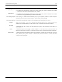
Solution Ultima 844/862/880 Wiring Diagram______________________________________________ 262
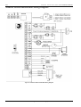
Solution Ultima 844/862/880 Component Overlay __________________________________________ 263
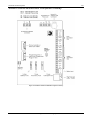
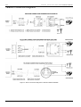
Telecom Connection Diagrams __________________________________________________________ 264
Appendices _____________________________________________________________________ 265
Appendix A _________________________________________________________________________ 266
Telephone Anti-Jamming_______________________________________________________________________266
Appendix B__________________________________________________________________________ 267
Test Reports Only When Armed _________________________________________________________________267
Specifications____________________________________________________________________269
Warranty Statement __________________________________________________________________ 270
Year 2000 Compliance ________________________________________________________________ 270
Specifications ________________________________________________________________________ 271
Software Version Number ______________________________________________________________________271
Advice To Users _____________________________________________________________________________271
New Zealand Telepermit Notes __________________________________________________________________272
Solution Ultima 844 ______________________________________________________________273
Programming Sheets______________________________________________________________273
Solution Ultima 862 ______________________________________________________________283
Programming Sheets______________________________________________________________283
Solution Ultima 880 ______________________________________________________________293
Programming Sheets______________________________________________________________293
Index __________________________________________________________________________303
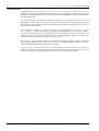
Introduction
This section includes the following;
•
Introduction
•
Solution Ultima 844 Features
•
Solution Ultima 862 Features
•
Solution Ultima 880 Features
•
Quick Start
•
Solution Ultima 844 Zones Defaults
•
Solution Ultima 862 Zone Defaults
•
Solution Ultima 880 Zone Defaults
•
Zone Types
18
Solution Ultima 844/862/880
Installation Manual
Introduction
Congratulations on selecting the Solution Ultima 844/862/880 control panel for your
installation. So that you can obtain the most from your unit, we suggest that you take the time to read
through this manual and familiarise yourself with the numerous outstanding operating and installation
features of this system.
You will notice that in all aspects of planning, engineering, styling, operation, convenience and
adaptability, we have sought to anticipate your every possible requirement. Programming simplicity
and speed have been some of the major considerations and we believe that our objectives in this area
have been more than satisfied.
This installation manual will explain all aspects of programming the Solution Ultima
844/862/880 control panel from factory default to final commissioning. All system parameters
and options are detailed, however, suitability is left up to the individual. Every control panel can be
tailored to meet all requirements quickly and easily. The programming simplicity will make your
installation quick, accurate and rewarding each and every time.
The Solution range of control panels are very popular amongst thousands of people throughout
many countries of the world, all who have various levels of technical aptitude and ability. We have
tried to aim this installation manual to all levels of readers.
As the Solution control panels continue to be improved over the years, they have become very
powerful. Some of its early first-time users have advanced to true "power users" and we need to
address their needs too, while maintaining the simplicity of the manual and the product.
ISSUE120.DOC
Electronics Design and Manufacturing Pty Limited
Introduction
19
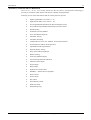
Solution Ultima 844 Features
The Solution Ultima 844 security system uses the very latest in microprocessor technology to
provide you with more useful features and superior reliability and performance.
Following is a list of the main features that the control panel will provide.
Ø
Eight Programmable User Codes (1 – 8)
Ø
Eight Remote Radio User Codes (9 – 16)
Ø
Four Programmable Hard Wired Or Wireless Burglary Zones
Ø
Four 24 Hour Programmable Hard Wired Or Wireless Zones
Ø
Dual Reporting
Ø
On-Board Line Fault Module
Ø
Telco Arm/Disarm Sequence
Ø
Automatic Arming
Ø
Automatic Disarming
Ø
Codepad Duress, Panic, Fire, Medical, Access Denied Alarms
Ø
STAY Mode and AWAY Mode Operation
Ø
Upload/Download Programmable
Ø
Dynamic Battery Testing
Ø
Entry and Exit Warning Beeper
Ø
Remote Arming
Ø
Answering Machine Bypass
Ø
AC Fail and System Fault Indicators
Ø
Monitored Siren Output
Ø
Strobe Output
Ø
Relay Output
Ø
Separate Fire Alarm Sound
Ø
EDMSAT – Satellite Siren Compatible
Ø
Zone Lockout
Ø
Sensor Watch
Ø
Day Alarm
Ø
Event Memory Recall
Ø
Walk Test Mode
Ø
Delayed Reporting
Electronics Design and Manufacturing Pty Limited
ISSUE120.DOC
Solution Ultima 844/862/880
20
Installation Manual
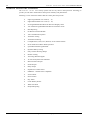
Solution Ultima 862 Features
The Solution Ultima 862 security system uses the very latest in microprocessor technology to
provide you with more useful features and superior reliability and performance.
Following is a list of the main features that the control panel will provide.
ISSUE120.DOC
Ø
Eight Programmable User Codes (1 – 8)
Ø
Eight Remote Radio User Codes (9 – 16)
Ø
Six Programmable Hard Wired Or Wireless Burglary Zones
Ø
Two 24 Hour Programmable Hard Wired Or Wireless Zones
Ø
Dual Reporting
Ø
On-Board Line Fault Module
Ø
Telco Arm/Disarm Sequence
Ø
Automatic Arming
Ø
Automatic Disarming
Ø
Codepad Duress, Panic, Fire, Medical, Access Denied Alarms
Ø
STAY Mode and AWAY Mode Operation
Ø
Upload/Download Programmable
Ø
Dynamic Battery Testing
Ø
Entry and Exit Warning Beeper
Ø
Remote Arming
Ø
Answering Machine Bypass
Ø
AC Fail and System Fault Indicators
Ø
Monitored Siren Output
Ø
Strobe Output
Ø
Relay Output
Ø
Separate Fire Alarm Sound
Ø
EDMSAT – Satellite Siren Compatible
Ø
Zone Lockout
Ø
Sensor Watch
Ø
Day Alarm
Ø
Event Memory Recall
Ø
Walk Test Mode
Ø
Delayed Reporting
Electronics Design and Manufacturing Pty Limited
Introduction
21
Solution Ultima 880 Features
The Solution Ultima 880 security system uses the very latest in microprocessor technology to
provide you with more useful features and superior reliability and performance.
Following is a list of the main features that the control panel will provide.
Ø
Eight Programmable User Codes (1 – 8)
Ø
Eight Variable User Codes (Radio Remote/Programmable User Codes (9 - 16))
Ø
Eight Programmable Hard Wired Or Wireless Burglary Zones
Ø
Partitionable To Two Separate Areas
Ø
Dual Reporting
Ø
On-Board Line Fault Module
Ø
Telco Arming/Disarming Sequence
Ø
Automatic Arming
Ø
Automatic Disarming
Ø
Codepad Duress, Panic, Fire, Medical, Access Denied Alarms
Ø
STAY Mode and AWAY Mode Operation
Ø
Upload/Download Programmable
Ø
Dynamic Battery Testing
Ø
Entry and Exit Warning Beeper
Ø
Remote Arming
Ø
Answering Machine Bypass
Ø
AC Fail and System Fault Indicators
Ø
Monitored Siren Output
Ø
Strobe Output
Ø
Relay Output
Ø
Separate Fire Alarm Sound
Ø
EDMSAT – Satellite Siren Compatible
Ø
Zone Lockout
Ø
Sensor Watch
Ø
Day Alarm
Ø
Event Memory Recall
Ø
Walk Test Mode
Ø
Delayed Reporting
Electronics Design and Manufacturing Pty Limited
ISSUE120.DOC
Solution Ultima 844/862/880
22
Installation Manual
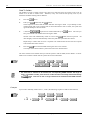
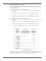
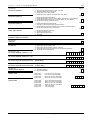
Quick Start
The following steps will allow you to use the Solution Ultima 844/862/880 control panel
with the factory default values. The default values allow the control panel to communicate in the
Contact ID format. If you are not familiar to programming the Solution range of control panels, we
suggest that you first read information contained in the programming section beginning on page 102.
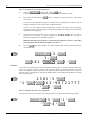
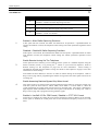
1.
2.
3.
4.
5.
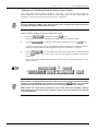
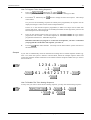
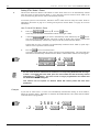
After all wiring has been completed, connect the AC plug pack to the control panel.
Both the MAINS and AWAY indicators will illuminate. The MAINS indicator will display to
indicate that the AC mains supply has been connected. The AWAY indicator displays that the
system is now armed in the AWAY Mode. If any 24-hour zones are unsealed at the time the
system is powered up, the siren, strobe and bell outputs will activate into alarm and the
corresponding zone indicator will flash.
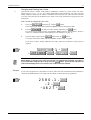
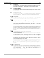
Enter the default Master Code 2580 followed by the
button to disarm the system
and to reset any alarm that may have occurred during the system power up. The AWAY
indicator will extinguish to indicate that the system has now been disarmed. If any zone
indicators are flashing, this would indicate that an alarm had occurred on that zone. If a zone
indicator is constantly illuminated, this would indicate that the zone is unsealed.
The back-up battery should now be connected.
Enter the factory default Installer Code 1234 followed by the
button. Two beeps
will be heard and the STAY and AWAY indicators will now flash simultaneously to indicate that
you have now entered Installer’s Programming Mode. When entering Installer’s Programming
Mode, you will be automatically positioned at “LOCATION 000”, the beginning of the
Primary Telephone Number For Receiver 1.
Enter the Primary Telephone Number followed by the Secondary Telephone Number and the
Subscriber ID Number for Receiver 1. Refer to Dialler Information on page 138 for more
information.
Remember that when programming a zero in the telephone numbers of Receiver 1 and
Receiver 2, a zero must be programmed as a ten. Programming a zero in the telephone number
will indicate the end of the dialling sequence. A zero must be programmed as a zero in all
locations other than the telephone numbers for Receiver 1, Receiver 2 and the Call Back
Telephone number, unless otherwise stated.
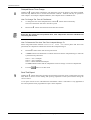
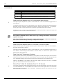
6.
7.
8.
ISSUE120.DOC
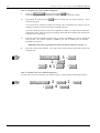
Set the time for the test reports if required. Any other programming changes required may also
be made, otherwise the factory default settings will be used. Refer to Test Reporting Time on
page 197 for more information on programming test reports.
Enter Installer’s Command 960 followed by the
button to exit Installer’s
Programming Mode. Two beeps will be heard and the STAY and AWAY indicators will
extinguish. The system has now returned to the disarmed state and is now ready for use. Refer
to Installer’s Programming Commands on page 107 for more information.
Use the Master Code to set the date and time. Refer to How To Set The Date and Time on
page 23 for more information.
Electronics Design and Manufacturing Pty Limited
Introduction
23
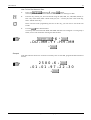
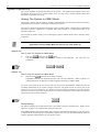
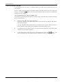
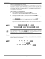
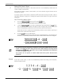
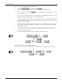
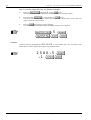
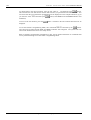
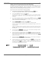
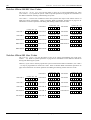
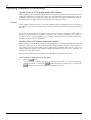
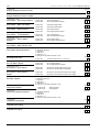
How To Set The Date and Time
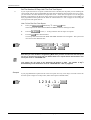
1.
2.
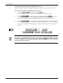
Enter your
followed by 6 and the
button.
Three beeps will be heard and the STAY and AWAY indicators will begin to flash.
Enter the day, month, year, hour and minute using the (DD, MM, YY, HH, MM) format (ie.
DD = Day of the month, MM = Month of the year, YY = Current year, HH = Hour of the day,
MM = Minute of the day).
Please note that when programming the hour of the day, you will need to use 24:00 hour
format.
3.
Press the
button when finished.
Two beeps will be heard and the STAY and AWAY indicators will extinguish. If a long beep is
heard, an error was made when entering the date and time.
+6+
+ DD + MM + YY + HH + MM
+
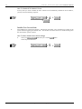
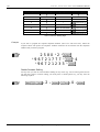
Example
If the date and time needs to be set for the 1st January 1997 at 10:30 PM, program the date and time as
follows;
2580 + 6 +
+ 01 + 01 + 97 + 22 + 30
+
Electronics Design and Manufacturing Pty Limited
ISSUE120.DOC
Solution Ultima 844/862/880
24
Installation Manual
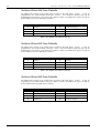
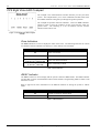
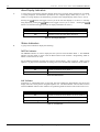
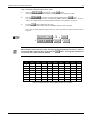
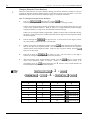
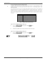
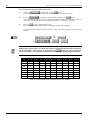
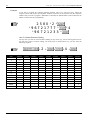
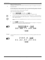
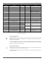
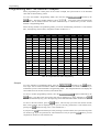
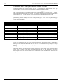
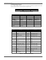
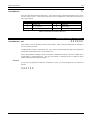
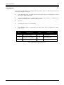
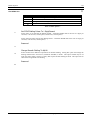
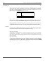
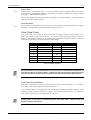
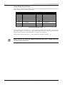
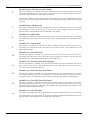
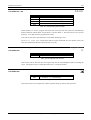
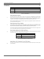
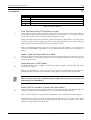
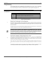
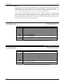
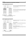
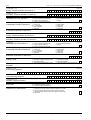
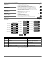
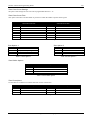
Solution Ultima 844 Zone Defaults
The default zone settings of the control panel are listed in the table below. Zones 1 – 4 may be
programmed to any of the available zone types. Zones 5 – 8 are limited to that they may only be
programmed to any 24 hour or keyswitch type. Refer to “Table 4: Available Zone Types” on page 25
for the different zone types that may be selected.
Zone No
Zone Type
Zone No
Zone Type
1
2
Delay-1
Handover
5
6
24 Hour Burglary
24 Hour Burglary
3
4
Handover
Instant
7
8
24 Hour Fire
24 Hour Tamper
Table 1: Zone Defaults For Solution Ultima 844
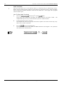
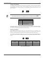
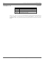
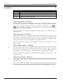
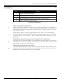
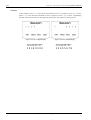
Solution Ultima 862 Zone Defaults
The default zone settings of the control panel are listed in the table below. Zones 1 – 6 may be
programmed to any of the available zone types. Zones 7 and 8 are limited to that they may only be
programmed to any 24 hour or keyswitch type. Refer to “Table 4: Available Zone Types” on page 25
for the different zone types that may be selected.
Zone No
Zone Type
Zone No
Zone Type
1
2
Delay-1
Handover
5
6
Instant
Instant
3
4
Handover
Handover
7
8
24 Hour Fire
24 Hour Tamper
Table 2: Zone Defaults For Solution Ultima 862
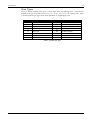
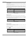
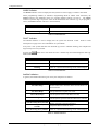
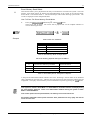
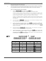
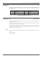
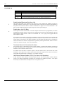
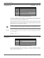
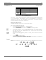
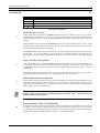
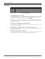
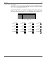
Solution Ultima 880 Zone Defaults
The default zone settings of the control panel are listed in the table below. Zones 1 – 8 may be
programmed to any of the available zone types. Refer to “Table 4: Available Zone Types” on page 25
for the different zone types that may be selected.
Zone No
Zone Type
Zone No
Zone Type
1
Delay-1
5
Instant
2
3
Handover
Handover
6
7
Instant
Instant
4
Handover
8
24 Hour Tamper
Table 3: Zone Defaults For Solution Ultima 880
ISSUE120.DOC
Electronics Design and Manufacturing Pty Limited
Introduction
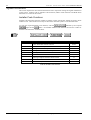
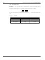
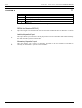
25
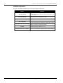
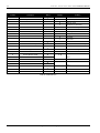
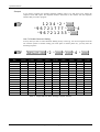
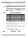
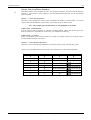
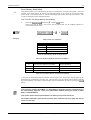
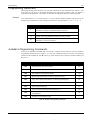
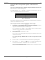
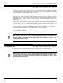
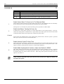
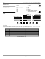
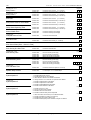
Zone Types
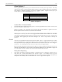
There are thirteen different zone types to choose from when programming zones. These thirteen
different zone types are available for all Solution Ultima 844/862/880 control panels. Refer
to Zone Programming on page 169 for more information on programming zones.
Zone Type
Description
Zone Type
Description
0
1
Instant
Handover
8
9
24 Hour Hold-Up
24 Hour Tamper
2
3
Delay-1
Delay-2
10
11
Reserved
Keyswitch
4
Reserved
12
24 Hour Burglary
5
6
Reserved
24 Hour Medical
13
14
24 Hour Fire
Chime Only
7
24 Hour Panic
15
Zone Not Used
Table 4: Available Zone Types
Electronics Design and Manufacturing Pty Limited
ISSUE120.DOC
26
ISSUE120.DOC
Solution Ultima 844/862/880
Electronics Design and Manufacturing Pty Limited
Installation Manual
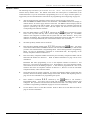
Codepad Indicators
This section includes the following;
•
CP5 Eight Zone LED Codepad
•
CP5 Eight Zone LCD Codepad
•
CP5 Master Partitioned LED Codepad
Solution Ultima 844/862/880
28
Installation Manual
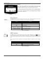
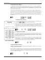
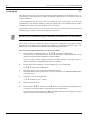
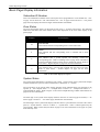
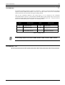
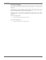
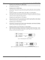
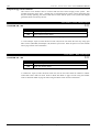
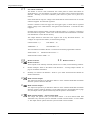
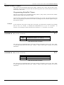
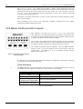
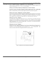
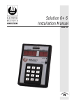
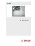
CP5 Eight Zone LED Codepad
The codepad is the communications interface between you and your alarm
system. The codepad allows you to issue commands and offers both visual
and audible indications that guide you through the general operation.
The codepad incorporates numerous indicators. There are ZONE indicators
which are used to show the condition of each zone and four others for
general status. The following is a list of situations and the relevant
indications that will be seen.
Figure 1: CP5 Eight Zone LED Codepad
(CP508)
Zone Indicators
The ZONE indicators are used to display the status of the zones. The following table lists the various
circumstances that the indicators will display (ie. Zone Sealed, Zone Unsealed).
Indicator
Definition
On
Zone Is Unsealed
Off
Zone Is Sealed
Flashing Fast
(0.25 Sec On – 0.25 Sec Off)
Flashing Slow
(1 Sec On – 1 Sec Off)
Zone Is In Alarm Condition
Zone Is Manually Isolated
Table 5: Zone Indicators
AWAY Indicator
The AWAY indicator is used to display that the system is armed in AWAY Mode. The AWAY indicator
will also flash in unison with the STAY indicator when Installer’s Programming Mode or Master Code
Functions are used.
Refer to page 40 for more information on the different methods on arming the system in AWAY
Mode.
Indicator
Definition
On
System Is Armed In AWAY Mode
Off
System Is Not Armed In AWAY Mode
Table 6: AWAY Indicator
ISSUE120.DOC
Electronics Design and Manufacturing Pty Limited
Codepad Indicators
29
STAY Indicator
The STAY indicator is used to display that the system is armed in STAY Mode 1 or STAY Mode 2.
The STAY indicator will also flash in unison with the AWAY indicator when Installer’s Programming
Mode or Master Code Functions are used.
For the different methods of arming the system in STAY Mode 1, refer to page 42. Refer to Zone
Options 2 on page 179 for information on setting zones to be automatically isolated in STAY Mode 1.
For the method of arming the system in STAY Mode 2, refer to page 45. Refer to Setting STAY
Mode 2 Zones on page 71 when using the Installer Code or Setting STAY Mode 2 Zones on page 86
when using the Master Code.
Indicator
Definition
On
System Is Armed In STAY Mode 1 Or STAY Mode 2
Off
System Is Not Armed In STAY Mode
Flashing
Once Every 3 Seconds
Zone Isolating Mode Or Setting STAY Mode 2 Zones
Day Alarm Status On/Off Indicator
Table 7: STAY Indicator
MAINS Indicator
The MAINS indicator is used to display that the systems AC mains supply is normal or has failed.
When programming numbers (ie. Installer’s Programming Mode or Master Code Functions), the
MAINS indicator will illuminate when you program numbers between 10 and 15. The MAINS
indicator represents digit 10 plus the value of the illuminated zone indicator (eg: If you program a
twelve, the MAINS indicator and zone 2 will illuminate).
Indicator
On
Flashing
Definition
AC Mains Power Normal
AC Mains Failure
Table 8: MAINS Indicator
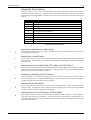
FAULT Indicator
The FAULT indicator is used to display that the system has detected a fault.
Descriptions on page 53 for more information on system faults.
Refer to Fault
Every time a new system fault has been detected (eg: FAULT indicator flashing), the codepad will
begin to beep once every minute.
Pressing the
button once will cancel the once a minute beep and acknowledge the fault (eg:
FAULT indicator on).
Indicator
Definition
On
There Is A System Fault That Needs To Be Rectified
Off
The System Is Normal, There Are No Faults
Flashing
There Is A System Fault Waiting To Be Acknowledged
Table 9: FAULT Indicator
Electronics Design and Manufacturing Pty Limited
ISSUE120.DOC
Solution Ultima 844/862/880
30
Installation Manual
Audible Indicators
In general, the audible indications given out by the codepad are as follows:
Indicator
Definition
One Short Beep
A Button Has Been Pressed On The Codepad Or End
Of Exit Time When Armed In Either STAY Mode 1 Or
STAY Mode 2
Two Short Beeps
The System Has Accepted Your Code
The Requested Function Has Been Executed
Three Short Beeps
Indicates The End Of Exit Time In AWAY Mode Or
The Requested Operation Has Been Denied Or Aborted
Walk Test Mode Is Currently Active Or Warning
Before Automatic Arming Takes Place
One Long Beep
One Short Beep Every Second
One Short Beep Every Two
Seconds
Telephone Monitor Mode Is Active
One Short Beep Every Minute
There Is A System Fault Waiting To Be Acknowledged
Table 10: Audible Indications
ISSUE120.DOC
Electronics Design and Manufacturing Pty Limited
Codepad Indicators
31
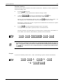
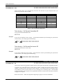
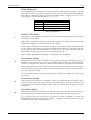
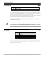
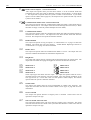
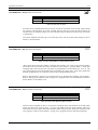
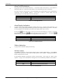
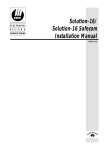
CP5 Eight Zone LCD Codepad
The codepad is the communications interface between you and your alarm
system. The codepad allows you to issue commands and offers both visual
and audible indications that guide you through the general operation.
The codepad incorporates numerous indicators. There are ZONE indicators
which are used to show the condition of each zone and seven others for
general status. The following is a list of situations and the relevant
indications that will be seen.
Figure 2: CP5 Eight Zone LCD Codepad
(CP508L)
Zone Indicators
1 2 3 ....
The ZONE indicators are used to display the status of the zones. The following table lists the various
circumstances that the indicators will display (ie. Zone Sealed, Zone Unsealed).
Indicator
Definition
On
Zone Is Unsealed
Off
Zone Is Sealed
Flashing Fast
(0.25 Sec On – 0.25 Sec Off)
Flashing Slow
(1 Sec On – 1 Sec Off)
Zone Is In Alarm Condition
Zone Is Manually Isolated
Table 11: Zone Indicators
AWAY Indicator
The AWAY indicator is used to display that the system is armed in AWAY Mode. The
indicator
will also illuminate when the system is armed in AWAY Mode. The AWAY indicator will also flash
in unison with the STAY indicator when Installer’s Programming Mode or Master Code Functions are
used.
Refer to page 40 for more information on the different methods on arming the system in AWAY
Mode.
Indicator
Definition
On
System Is Armed In AWAY Mode
Off
System Is Not Armed In AWAY Mode
Table 12: AWAY Indicator
Electronics Design and Manufacturing Pty Limited
ISSUE120.DOC
Solution Ultima 844/862/880
32
Installation Manual
STAY Indicator
The STAY indicator is used to display that the system is armed in STAY Mode 1 or STAY Mode 2.
The STAY indicator will also flash in unison with the AWAY indicator when Installer’s Programming
Mode or Master Code Functions are used.
The
2.
indicator will also illuminate when the system is armed in STAY Mode 1 or STAY Mode
For the different methods of arming the system in STAY Mode 1, refer to page 42. Refer to Zone
Options 2 on page 179 for information on setting zones to be automatically isolated in STAY Mode 1.
For the method of arming the system in STAY Mode 2, refer to page 45. Refer to Setting STAY
Mode 2 Zones on page 71 when using the Installer Code or Setting STAY Mode 2 Zones on page 86
when using the Master Code.
Indicator
Definition
On
System Is Armed In STAY Mode 1 Or STAY Mode 2
Off
System Is Not Armed In STAY Mode
Flashing
Once Every 3 Seconds
Zone Isolating Mode Or Setting STAY Mode 2 Zones
Day Alarm Status On/Off Indicator
Table 13: STAY Indicator
System Disarmed
This indicator will illuminate with the
indicator when the system has been disarmed.
MAINS Indicator
The MAINS indicator is used to display that the systems AC mains supply is normal or has failed.
When programming numbers (ie. Installer’s Programming Mode or Master Code Functions), the
MAINS indicator will illuminate when you program numbers between 10 and 15. The MAINS
indicator represents digit 10 plus the value of the illuminated zone indicator (eg: If you program a
twelve, the MAINS indicator and zone 2 will illuminate).
Indicator
On
Flashing
Definition
AC Mains Power Normal
AC Mains Failure
Table 14: MAINS Indicator
ISSUE120.DOC
Electronics Design and Manufacturing Pty Limited
Codepad Indicators
33
FAULT Indicator
The FAULT indicator is used to display that the system has detected a fault.
Descriptions on page 53 for more information on system faults.
Refer to Fault
Every time a new system fault has been detected (eg: FAULT indicator flashing), the codepad will
begin to beep once every minute.
Pressing the
button once will cancel the once a minute beep and acknowledge the fault (eg:
FAULT indicator on).
Indicator
Definition
On
There Is A System Fault That Needs To Be Rectified
Off
The System Is Normal, There Are No Faults
There Is A System Fault Waiting To Be Acknowledged
Flashing
Table 15: FAULT Indicator
Programming Mode
These two indicators will flash when the system has entered either Installer’s Programming Mode or
when any Master Code Functions are used.
Flashing
Off Indicator/Zone Sealed
The
indicator will illuminate when the system is in the disarmed state or Installer’s
Programming Mode has been entered and will flash when a zone becomes unsealed during the
disarmed state. The indicator will stop flashing when all zones are sealed.
On Indicator/Zone In Alarm
The
indicator will illuminate when the system is armed in AWAY Mode and will flash when an
alarm occurs. The indicator will reset once a valid user code has been entered.
Electronics Design and Manufacturing Pty Limited
ISSUE120.DOC
Solution Ultima 844/862/880
34
Installation Manual
Audible Indicators
In general, the audible indications given out by the codepad are as follows:
Indicator
Definition
One Short Beep
A Button Has Been Pressed On The Codepad Or End
Of Exit Time When Armed In Either STAY Mode 1 Or
STAY Mode 2
Two Short Beeps
The System Has Accepted Your Code
The Requested Function Has Been Executed
Three Short Beeps
Indicates The End Of Exit Time In AWAY Mode Or
The Requested Operation Has Been Denied Or Aborted
Walk Test Mode Is Currently Active Or Warning
Before Automatic Arming Takes Place
One Long Beep
One Short Beep Every Second
One Short Beep Every Two
Seconds
Telephone Monitor Mode Is Active
One Short Beep Every Minute
There Is A System Fault Waiting To Be Acknowledged
Table 16: Audible Indications
ISSUE120.DOC
Electronics Design and Manufacturing Pty Limited
Codepad Indicators
35
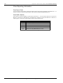
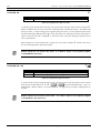
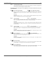
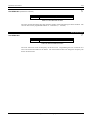
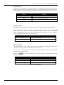
CP5 Master Partitioned LED Codepad
This codepad is only used on the Solution Ultima 880 control panel
when partitioned. The Master Partitioned LED codepad will allow the user
to operate both areas individually from the same codepad, without the need
to operate individual areas from separate codepads.
The codepad is the communications interface between you and your alarm
system. The codepad allows you to issue commands and offers both visual
and audible indications that guide you through the general operation.
Figure 3: CP5 Master Partitioned LED
Codepad (CP500P)
The codepad incorporates numerous indicators. There are ZONE indicators
which are used to show the condition of each zone and four others for
general status. The following is a list of situations and the relevant
indications that will be seen.
Refer to Partitioning on page 235 for more information.
The indicators on the CP5 Master Partitioned LED codepad are configured in to four groups.
Following is a description of what the indicators mean.
Zone Indicators
1
The ZONE indicators are used to display the status of the zones. The following table lists the various
circumstances that the indicators will display (ie. Zone Sealed, Zone Unsealed).
Indicator
Definition
On
Zone Is Unsealed
Off
Zone Is Sealed
Flashing Fast
(0.25 Sec On – 0.25 Sec Off)
Flashing Slow
(1 Sec On – 1 Sec Off)
Zone Is In Alarm Condition
Zone Is Manually Isolated
Table 17: Zone Indicators
Area On/Off Indicators
2
The group of four Area On/Off indicators (1 – 4) show the status of each area (ie. If an indicator is
illuminated, that area is armed and if the indicator is not illuminated, that area is disarmed).
If an area is armed in STAY Mode 1, the corresponding Area On/Off indicator will be illuminated in
conjunction with the PARTIAL indicator. If the area is armed in AWAY Mode, only the
corresponding Area On/Off Indicator will be illuminated.
Area On/Off Indicator
Definition
On
Area Is Armed In AWAY Mode Or STAY Mode 1
Off
Area Is Disarmed
Table 18: Area On/Off Indicators
Electronics Design and Manufacturing Pty Limited
ISSUE120.DOC
Solution Ultima 844/862/880
36
Installation Manual
Area Display Indicators
3
A group of four Area Display indicators display which area is currently being displayed (ie. If number
1 is being displayed, all information provided on the codepad display relates only to Area 1. If
number 2 is being displayed, all information provided on the codepad display relates only to Area 2).
Pressing the
button will toggle or move you to the next area display (ie. If Area 1 is currently
being displayed, pressing the
button will toggle or move you to Area 2. Pressing the
button a second time will toggle you back to display information for Area 1).
Area Display Indicators
Definition
On
Indicates Current Area Being Displayed
Off
Indicates Current Area Not Being Displayed
Table 19: Area Display Indicators
Status Indicators
4
A group of four indicators display the following:
PARTIAL Indicator
The PARTIAL indicator is used to display that the system is armed in STAY Mode 1. The PARTIAL
indicator will also flash in unison with the AUX indicator when Installer’s Programming Mode or
Master Code Functions are used.
For the different methods of arming the system in STAY Mode 1, refer to page 42. Refer to Zone
Options 1 on page 169 for information on setting zones to be automatically isolated in STAY Mode 1.
Indicator
Definition
On
System Is Armed In STAY Mode 1
Off
System Is Not Armed In STAY Mode 1
Table 20: Partial Indicator
AUX Indicator
If Option 8 in “LOCATION 444” on page 241 has been enabled, the AUX indicator will be used to
display when the control panel is using the telephone line. The AUX indicator will also flash in unison
with the PARTIAL indicator when Installer’s Programming Mode or Master Code Functions are used.
Indicator
Definition
On
System Is Armed In STAY Mode 1 Or STAY Mode 2
Off
System Is Not Armed In STAY Mode
Flashing
Zone Isolating Mode Or Setting STAY Mode 2 Zones
Table 21: AUX Indicator
ISSUE120.DOC
Electronics Design and Manufacturing Pty Limited
Codepad Indicators
37
MAINS Indicator
The MAINS indicator is used to display that the systems AC mains supply is normal or has failed.
When programming numbers (ie Installer’s Programming Mode or Master Code Functions), the
MAINS indicator will illuminate when you program numbers between 10 and 15. The MAINS
indicator represents digit 10 plus the value of the illuminated zone indicator (eg: If you program a
twelve, the MAINS indicator and zone 2 will illuminate).
Indicator
Definition
AC Mains Power Normal
On
AC Mains Failure
Flashing
Table 22: MAINS Indicator
FAULT Indicator
The FAULT indicator is used to display that the system has detected a fault.
Descriptions on page 53 for more information on system faults.
Refer to Fault
Every time a new system fault has been detected (eg: FAULT indicator flashing), the codepad will
begin to beep once every minute.
Pressing the
button once will cancel the once a minute beep and acknowledge the fault (eg:
FAULT indicator on).
Indicator
Definition
On
There Is A System Fault That Needs To Be Rectified
Off
The System Is Normal, There Are No Faults
There Is A System Fault Waiting To Be Acknowledged
Flashing
Table 23: FAULT Indicator
Audible Indicators
In general, the audible indications given out by the codepad are as follows:
Indicator
Definition
One Short Beep
A Button Has Been Pressed On The Codepad Or End
Of Exit Time When Armed In Either STAY Mode 1 Or
STAY Mode 2
Two Short Beeps
The System Has Accepted Your Code
The Requested Function Has Been Executed
Three Short Beeps
Indicates The End Of Exit Time In AWAY Mode Or
The Requested Operation Has Been Denied Or Aborted
Walk Test Mode Is Currently Active Or Warning
Before Automatic Arming Takes Place
One Long Beep
One Short Beep Every Second
One Short Beep Every Two
Seconds
Telephone Monitor Mode Is Active
One Short Beep Every Minute
There Is A System Fault Waiting To Be Acknowledged
Table 24: Audible Indications
Electronics Design and Manufacturing Pty Limited
ISSUE120.DOC
38
ISSUE120.DOC
Solution Ultima 844/862/880
Electronics Design and Manufacturing Pty Limited
Installation Manual
System Operations
This section includes the following;
•
Arming The System In AWAY Mode
•
Disarming The System From AWAY Mode
•
Arming The System In STAY Mode 1
•
Disarming The System From STAY Mode 1
•
Arming The System In STAY Mode 2
•
Disarming The System From STAY Mode 2
•
Codepad Duress Alarm
•
Codepad Panic Alarm
•
Codepad Fire Alarm
•
Codepad Medical Alarm
•
Isolating Zones
•
Fault Analysis Mode
Solution Ultima 844/862/880
40
Installation Manual
System Operations
This section explains the general operations of the system. The operations will explain how to arm
and disarm the system in the various modes, how to isolate zones, initiate codepad alarms and
determine any fault that may occur.
Arming The System In AWAY Mode
Arming the system in AWAY Mode is normally performed when you leave the premises and require
that all zones be activated in a ready state to detect any intrusion.
There are two different methods for arming the system in AWAY Mode. Method one is standard and
will always operate. Method two is optional and requires Option 2 in "LOCATION 441" to be
enabled on page 232.
If you require to isolate a zone(s) prior to arming the system in AWAY Mode, refer to Isolating Zones
on page 48.
Single button arming in AWAY Mode will report as user code number 16.
Method One
How To Arm The System In AWAY Mode
1.
Enter your
followed by the
button.
Two beeps will be heard and the AWAY indicator will illuminate.
commence.
Exit time will now
+
Method Two
How To Arm The System In AWAY Mode
1.
Hold down the
button until two beeps are heard.
The AWAY indicator will illuminate and exit time will now commence. Refer to Option 2 in
"LOCATION 441" on page 232 to enable single button arming in AWAY Mode.
If a zone is not sealed at the end of exit time, the zone will be automatically isolated and will be
constantly illuminated on the remote codepad. The zone will again become an active part of the
system as soon as it has resealed (ie. If a window is left open after exit time has expired, the window
will not be an active part of the system until it has closed. Opening the window after exit time has
expired will cause an alarm condition).
Forced Arming
The feature of arming the system when a zone is not sealed is known as forced arming. Refer to Zone
Options 2 on page 179 to enable forced arming for each zone.
If the AWAY indicator does not illuminate and a long beep is heard when attempting to arm the system
in AWAY Mode, forced arming is not permitted. If this is the case, you must ensure that all zones are
sealed or manually isolated before you can arm the system.
ISSUE120.DOC
Electronics Design and Manufacturing Pty Limited
System Operations
41
Disarming The System From AWAY Mode
When you enter the premises after the system has been armed in AWAY Mode, you will need to
disarm the system from AWAY Mode to disable detection devices that will activate the sirens, strobe
and bell outputs.
If there has been an alarm condition prior to disarming the system from AWAY Mode, a flashing
ZONE indicator will be displayed, indicating a previous alarm on that zone.
How To Disarm The System From AWAY Mode
1.
Enter your
followed by the
button.
Two beeps will be heard and the AWAY indicator will extinguish.
+
Electronics Design and Manufacturing Pty Limited
ISSUE120.DOC
Solution Ultima 844/862/880
42
Installation Manual
Arming The System In STAY Mode 1
Arming the system in STAY Mode 1 is only used when the perimeter and unused areas of the
premises need to be armed to detect any would be intruder from entering the premises, at the same
time allowing you to move freely within an area which has been automatically isolated.
Programming zones to be automatically isolated in STAY Mode 1 can only be programmed by the
installer. Refer to Zone Options 2 on page 179 for further information on setting zones to be
automatically isolated in STAY Mode 1.
There are two methods for arming your system in STAY Mode 1. Method one is standard and will
always operate. Method two is optional and requires Option 2 in "LOCATION 441" to be enabled on
page 232.
When reporting back to base, a “Partial Close” report (Contact ID Event Code 456) will be sent.
Entry Guard Timer For STAY Mode
When arming the system in STAY Mode 1, an optional entry timer called Entry Guard Timer For
STAY Mode may be used to delay the sirens, strobe and bell outputs if a zone that has not been
automatically isolated has triggered into alarm condition. Entry Guard Timer For STAY Mode is the
delay time used for all zones except 24 hour zones when the system is armed in STAY Mode 1 or
STAY Mode 2.
If the Entry Guard Timer For STAY Mode has been programmed and a zone that has not been
automatically isolated has triggered, the codepad will beep twice a second until the Entry Guard Timer
For STAY Mode has expired or the system has been disarmed. If the alarm condition has not been
reset before Entry Guard Timer For STAY Mode expires, the strobe, bell and siren outputs will
activate into alarm.
Single button arming in STAY Mode 1 will report as user code number 16.
Method One
How To Arm The System In STAY Mode 1
1.
followed by the
button.
Enter your
Two beeps will be heard and the STAY indicator will illuminate.
commence.
Exit time will now
Any zones that have been programmed to be automatically isolated in STAY Mode 1 will
begin to flash until exit time expires. At the end of exit time, the ZONE indicators will
extinguish and the codepad will give one short beep.
+
ISSUE120.DOC
Electronics Design and Manufacturing Pty Limited
System Operations
43
Method Two
How To Arm The System In STAY Mode 1
1.
Hold down the
button until two beeps are heard.
The STAY indicator will illuminate and exit time will now commence.
Any zones that have been programmed to be automatically isolated in STAY Mode 1 will
begin to flash until exit time expires. At the end of exit time, the ZONE indicators will
extinguish and the codepad will give one short beep.
If a zone is not sealed at the end of exit time, the zone will be automatically isolated and will be
constantly illuminated on the remote codepad. The zone will again become an active part of the
system as soon as it has resealed (ie. If a window is left open after exit time has expired, the window
will not be an active part of the system until it has closed. Opening the window after exit time has
expired will cause an alarm condition).
Forced Arming
The feature of arming the system when a zone is not sealed is known as forced arming. Refer to Zone
Options 2 on page 179 to enable forced arming for each zone.
If the STAY indicator does not illuminate and a long beep is heard when attempting to arm the system
in STAY Mode 1, forced arming is not permitted. If this is the case, you must ensure that all zones
are sealed or manually isolated before you can arm the system.
Electronics Design and Manufacturing Pty Limited
ISSUE120.DOC
Solution Ultima 844/862/880
44
Installation Manual
Disarming The System From STAY Mode 1
There are two methods for disarming the system from STAY Mode 1. Method one is standard and
will always operate. Method two is optional and needs Option 4 to be enabled in "LOCATION 441"
on page 232.
Method One
How To Disarm The System From STAY Mode 1
1.
Enter your
followed by the
button.
Two beeps will be heard and the STAY indicator will extinguish. The system is now disarmed.
+
Method Two
A flashing ZONE indicator represents a previous alarm on that zone. If this is the case, a valid user
code will need to be used to disarm the system using method one. To enable method two, Option 4 in
"LOCATION 441" on page 232 will need to be enabled.
How To Disarm The System From STAY Mode 1
1.
Hold down the
button until two beeps are heard.
The STAY indicator will extinguish and the system is now disarmed.
Single button disarming from STAY Mode 1 will report as user code number 16.
ISSUE120.DOC
Electronics Design and Manufacturing Pty Limited
System Operations
45
Arming The System In STAY Mode 2
Arming the system in STAY Mode 2 is only used when the perimeter and unused areas of the
premises need to be armed to detect any would be intruder from entering the premises, at the same
time allowing you to move freely within an area which has been automatically isolated.
Programming zones to be automatically isolated in STAY Mode 2 can be programmed either by the
Installer Code Function – Setting STAY Mode 2 Zones on page 71 or Master Code Functions Setting STAY Mode 2 Zones on page 86.
When reporting back to base, a “Partial Close” report (Contact ID Event Code 456) will be sent.
Entry Guard Timer For STAY Mode
When arming the system in STAY Mode 2, an optional entry timer called Entry Guard Timer For
STAY Mode may be used to delay the sirens, strobe and bell outputs if a zone that has not been
automatically isolated has triggered into alarm condition. Entry Guard Timer For STAY Mode is the
delay time used for all zones except 24 hour zones when the system is armed in STAY Mode 1 or
STAY Mode 2.
If the Entry Guard Timer For STAY Mode has been programmed and a zone that has not been
automatically isolated has triggered, the codepad will beep twice a second until the Entry Guard Timer
For STAY Mode has expired or the system has been disarmed. If the alarm condition has not been
reset before Entry Guard Timer For STAY Mode expires, the strobe, bell and siren outputs will
activate into alarm.
Single button arming in STAY Mode 2 will report as user code number 16.
How To Arm The System In STAY Mode 2
1.
Hold down the 0 button until two beeps are heard.
The STAY indicator will illuminate and exit time will now commence.
Any zones that have been programmed to be automatically isolated in STAY Mode 2 will
begin to flash until exit time expires. At the end of exit time, the ZONE indicators will
extinguish and the codepad will give one short beep.
0
If a zone is not sealed at the end of exit time, the zone will be automatically isolated and will be
constantly illuminated on the remote codepad. The zone will again become an active part of the
system as soon as it has resealed (ie. If a window is left open after exit time has expired, the window
will not be an active part of the system until it has closed. Opening the window after exit time has
expired will cause an alarm condition).
Forced Arming
The feature of arming the system when a zone is not sealed is known as forced arming. Refer to Zone
Options 2 on page 179 to enable forced arming for each zone.
If the STAY indicator does not illuminate and a long beep is heard when attempting to arm the system,
forced arming is not permitted. If this is the case, you must ensure that all zones are sealed or
manually isolated before you can arm the system.
Electronics Design and Manufacturing Pty Limited
ISSUE120.DOC
Solution Ultima 844/862/880
46
Installation Manual
Disarming The System From STAY Mode 2
There are two methods for disarming the system from STAY Mode 2. Method one is standard and
will always operate. Method two is optional and requires Option 4 to be enabled in "LOCATION
441" on page 232.
Method One
How To Disarm The System From STAY Mode 2
1.
Enter your
followed by the
button.
Two beeps will be heard and the STAY indicator will extinguish. The system is now disarmed.
+
Method Two
A flashing ZONE indicator represents a previous alarm on that zone. If this is the case a valid user
code will need to be used to disarm the system using method one. To enable method two, Option 4 in
"LOCATION 441" on page 232 will need to be programmed.
How To Disarm The System From STAY Mode 2
1.
Hold down the 0 button until two beeps are heard.
The STAY indicator will extinguish and the system is now disarmed.
0
Single button disarming from STAY Mode 2 will report as user code number 16.
ISSUE120.DOC
Electronics Design and Manufacturing Pty Limited
System Operations
47
Codepad Duress Alarm
A codepad duress alarm is used as a silent hold up alarm. This will only occur when the number 9 is
added to the end of any valid user code that is being used to disarm the system. However, if a user
code has a priority level of arming only, entering their user code followed by 9 will still send a duress
alarm when the system is armed.
A duress alarm (Contact ID Event Code 121) is only useful if your system is reporting back to a
monitoring station or pocket pager as domestic reporting format can’t decipher which type of alarm
had occurred. If you wish to disable the codepad duress alarm report, refer to “LOCATION 348” on
page 190 for more information. If you require to activate a duress alarm by adding a number 3 to
the end of any valid user code being used to disarm the system, enable Option 2 in “LOCATION 442”
on page 233.
+9+
Codepad Panic Alarm
An audible codepad panic alarm will be activated when both the
or both the
and
buttons are pressed simultaneously.
1 and 3 buttons
Refer to Option 1 in "LOCATION 437" on page 228 if you wish to program codepad
panic to be silent. If you wish to disable the codepad panic alarm report, refer to
“LOCATION 349 - 350” on page 190 for more information. A codepad panic alarm
will send a Contact ID Event Code 120 when reporting back to a base station
receiver.
1 + 3 or
+
Codepad Fire Alarm
An audible codepad fire alarm will be activated when both the 4 and 6 buttons on
the remote codepad are pressed simultaneously. A distinct fire sound is emitted
through the horn speaker to indicate this type of alarm condition. The fire sound is
different to the burglary sound.
Figure 4: CP5 LED Codepad
Showing Audible Alarm Buttons
Refer to Option 2 in "LOCATION 437" on page 228 if you wish to program codepad
fire to be silent. If you wish to disable the codepad fire alarm report, refer to
“LOCATION 351 - 352” on page 191 for more information. A codepad fire alarm
will send a Contact ID Event Code 110 to a base station receiver.
4+6
Codepad Medical Alarm
An audible codepad medical alarm will be triggered when both the 7 and 9 buttons on the remote
codepad are pressed simultaneously.
Refer to Option 4 in "LOCATION 437" on page 228 if you wish to program codepad medical to be
silent. If you wish to disable the reporting of the codepad medical alarm report, refer to “LOCATION
353 - 354” on page 191 for more information. A codepad medical alarm will send a Contact ID Event
Code 100 to a base station receiver.
7+9
Electronics Design and Manufacturing Pty Limited
ISSUE120.DOC
Solution Ultima 844/862/880
48
Installation Manual
Isolating Zones
Isolating zones allow you to manually disable one or more zones before arming the system in AWAY
Mode, STAY Mode 1 or STAY Mode 2. Once a zone has been isolated, access is allowed into that
zone during the armed state without activating the sirens or dialler.
An example when you may require to isolate a zone before arming in AWAY Mode, STAY Mode 1
or STAY Mode 2 may be when a zone PIR detector may be false alarming or that you may need to
leave a pet inside a particular zone whilst you are away.
Isolating zones is performed by one of two methods. One way requires the use of a valid user code
while the other way does not. The ability to isolate zones is governed by the priority level allocated to
each user code holder. Some user code holders may not be able to isolate zones. Refer to User Code
Priority on page 161 for further information. At factory default, the standard method for isolating
zones is used.
Zones that have been manually isolated using this method will send a zone bypass report (Contact ID
Event Code 570) for each zone upon arming the system. A zone bypass restore report will be sent
when the system has been disarmed.
When you select a 24-hour burglary zone to be isolated, a Contact ID Event Code 572 will be sent. If
you select a 24-hour fire zone to be isolated, a Contact ID Event Code 571 will be sent.
ISSUE120.DOC
Electronics Design and Manufacturing Pty Limited
System Operations
49
Standard Isolating
Standard isolating allows all operators to be able to isolate zones. Therefore, no code is required to be
used when isolating zones.
1.
Press the
button twice.
Three beeps will be heard and the STAY indicator will begin to flash.
2.
* Enter the
required to be isolated followed by the
The zone you just selected to be isolated will now begin to flash.
button.
24-hour zones will automatically isolate as soon as the
button has been pressed. All
other burglary zones will automatically isolate only after the system has been armed.
Repeat Step 2 if more than one zone is required to be isolated until all zones that are required
to be isolated have been selected.
3.
Press the
button when finished selecting the zones to be isolated.
Two beeps will be heard and the system will return to the disarmed state.
The zones selected to be isolated when you arm the system in AWAY Mode, STAY Mode 1 or
STAY Mode 2 will continue to flash until the system has next been disarmed.
+
*
+
+
+
As each zone is selected to be isolated, the corresponding ZONE indicator will begin to
flash. If a mistake is made, press the zone number that was incorrectly entered followed by
the
button. This zone is now no longer selected to be isolated and the ZONE indicator
will extinguish.
Example
If you wish to manually isolate zones 1, 3 and 4, the following sequence would be entered below;
+
+1+
+4+
+3+
+
Electronics Design and Manufacturing Pty Limited
ISSUE120.DOC
Solution Ultima 844/862/880
50
Installation Manual
Code To Isolate
The method of code to isolate restricts only those user codes that have the priority level Code To
Isolate set to be able to isolate zones. Therefore, if any user code has this priority level set, the
method of standard isolating will be disabled.
1.
Press the
button.
2.
Enter your
followed by the
button.
Three beeps will be heard and the STAY indicator will begin to flash. If you attempt to enter
isolating mode with a user code that has not been allocated for code to isolate, the system will
ignore the attempt to enter the mode.
3.
* Enter the
required to be isolated followed by the
have just selected to be isolated will now begin to flash.
button. The zone you
24-hour zones will automatically isolate as soon as the
button has been pressed. All
other burglary zones will automatically isolate only after the system has been armed.
Repeat Step 3 if more than one zone is required to be isolated until all zones that are required
to be isolated have been selected.
4.
Press the
button when finished selecting the zones to be isolated.
Two beeps will be heard and the system will return to the disarmed state.
The zones selected to be isolated when you arm the system in AWAY Mode, STAY Mode 1 or STAY
Mode 2 will continue to flash until the system has next been disarmed.
+
+
*
+
+
+
As each zone is selected to be isolated, the corresponding ZONE indicator will begin to
flash. If a mistake is made, press the zone number that was incorrectly entered followed by
the
button. This zone is now no longer selected to be isolated and the ZONE indicator
will extinguish.
Example
If you wish to manually isolate zones 1, 3 and 4, the following sequence would be entered below;
+
+1+
ISSUE120.DOC
+3+
+
+4+
Electronics Design and Manufacturing Pty Limited
+
System Operations
51
Fault Analysis Mode
If a fault should occur, the FAULT or MAINS indicator will flash and the codepad will beep once
every minute.
If the AC mains supply has failed, the MAINS indicator will flash until the AC mains supply has
restored. Pressing the
button once will acknowledge the fault and stop the codepad from
beeping once every minute.
How To Determine The Type Of System Fault
To determine all system faults other than the AC mains supply, enter fault analysis mode by following
the steps outlined below.
1.
Hold down button 5 until two beeps are heard.
The FAULT indicator will remain steady and the STAY and AWAY indicators will flash in
unison with each other.
Any zone indicators displayed indicate the type of fault that has occurred. Refer to Table 25:
Fault Indicators on page 52 for the list of different system faults that may occur.
2.
To further determine the fault condition, you will need to hold down the corresponding button
to that of the zone indicator displayed.
3.
To exit fault analysis mode and return to the disarmed state, press the
button. The
FAULT indicator will remain displayed and the codepad will cease its once a minute beep.
Electronics Design and Manufacturing Pty Limited
ISSUE120.DOC
Solution Ultima 844/862/880
52
Installation Manual
Zone
Indicator
Fault
Description
Hold Down
Button
Zone
Indicator
Fault
Condition
1
System Fault
1
1
Low Battery
2
3
Date & Time
RF Receiver Jamming
RF Receiver Tamper Switch
RF Receiver Comms Failure
4
5
Horn Speaker
Telephone Line Fail
6
7
E2 Fault
Fuse Fail
2
RF Low Battery
2
1-8
Zones 1 - 8 RF Low Battery
3
Zone Tamper Alarm
3
1-8
Zones 1 - 8 Tamper Alarm
4
Sensor Watch Fault
4
1-8
Zones 1 – 8 Sensor Watch
Fail
5
RF Sensor Watch
5
1–8
Zones 1 - 8 RF Sensor Watch
Fail
6
Communication Fail
6
1
Receiver 1 Fail
2
Receiver 2 Fail
Table 25: Fault Indicators
ISSUE120.DOC
Electronics Design and Manufacturing Pty Limited
System Operations
53
Fault Descriptions
1
System Fault
A system fault will only display when any of the following faults occur. After entering fault analysis
mode, holding down button 1 will determine which of the following faults have occurred.
Low Battery
A low battery fault will register when the system detects a low capacity back-up battery. The system
automatically performs a battery test every 4 hours and also every time you arm the system.
Date and Time
The date and time fault will register every time the system has been powered down. This type of fault
will not cause the FAULT indicator to display on the codepad unless your installer has programmed
the automatic arming time. To program the date and time, refer to page 89.
RF Receiver Fail
The RF receiver fault will register once the system has detected that the RF wireless receiver unit has
registered RF Jamming, the RF wireless receiver has been disconnected from the control panel or has
failed, or the RF receiver’s cover tamper switch has been activated.
Horn Speaker
This fault will register when the system detects that the horn speaker has been disconnected. This
fault will clear once the horn speaker has been reconnected. Your installer will need to program the
system for this feature to operate.
Telephone Line Fail
A telephone line fault will register when the system detects that the telephone line has been
disconnected from the control panel. Your installer will need to program the system for this feature to
operate.
E2 Fault
An E2 fault will register when the system detects an internal checksum error. Contact your installer as
soon as this fault is displayed.
Fuse Fail
This fault will occur when either of the two 1 Amp fuses has blown. Contact your installer as soon as
this fault is displayed.
2
RF Low Battery
This fault will occur when any wireless zone (1 – 8) has reported a low battery condition to the control
panel. Whilst you are in fault analysis mode, holding down button 2 until two beeps are heard will
display which zone has reported the RF Low Battery fault.
Electronics Design and Manufacturing Pty Limited
ISSUE120.DOC
Solution Ultima 844/862/880
54
3
Installation Manual
Tamper Fail
This fault will occur when any zone has become open circuit. By holding down button 3 until two
beeps are heard in fault analysis mode will display which zone has reported the tamper fail fault.
4
Sensor Watch Fault
A sensor watch fault will register because one or more detection devices has failed to detect any
intrusion during the disarmed state for the time period programmed by your installer. The fault will
clear once the zone in question has detected movement and reset.
Whilst you are in fault analysis mode, holding down button 4 until two beeps are heard will display
which zone reported the sensor watch fault.
5
RF Sensor Watch Fault
An RF sensor watch fault will register because one or more wireless detection devices has failed to
detect any intrusion during the disarmed state for the time period programmed by your installer. The
fault will clear once the zone in question has detected movement and reset.
Whilst you are in fault analysis mode, holding down button 5 until two beeps are heard will display
which zone reported the sensor watch fault.
6
Communication Fail
A communication fail will register when the control panel failed to communicate with the receiving
party (eg: monitoring company, mobile phone or pocket pager etc).
The communication fault will clear once the control panel has successfully reported to the receiving
party.
Whilst you are in fault analysis mode, holding down the 6 button until two beeps are heard will
display which communication fault has occurred (ie. 1 = Receiver 1 / 2 = Receiver 2).
AC Mains Failure
An AC mains supply failure will automatically flash the MAINS indicator. If the AC mains supply has
been disconnected continuously for more than two minutes, the remote codepad will beep the codepad
buzzer once every minute. If the control panel has been programmed to report an AC mains fail to a
base station receiver, an “AC Fail" report (Contact ID Event Code 301) will be sent.
The MAINS indicator will cease to flash as soon as the AC mains supply has been reconnected. When
the AC mains supply has been continuously connected for a period of two minutes, the codepad will
cease the once a minute beep and an “AC Fail” restore report will be sent to the base station receiver.
If Option 1 – Enable AC Fail In 1 Hour in “LOCATION 438” on page 229 has been enabled, the
codepad will flash the MAINS indicator as soon as the AC mains supply has been disconnected and
will not activate the dialler or the codepad buzzer unless the AC mains supply has been disconnected
continuously for a period of 1 hour.
If Option 2 – Ignore AC Mains Fail in “LOCATION 438” on page 229 has been enabled, the codepad
will not indicate when the AC mains supply has failed, but the control panel will still report if enabled
an "AC Fail" report.
ISSUE120.DOC
Electronics Design and Manufacturing Pty Limited
Remote Radio Transmitter
Operations
This section includes the following;
•
Remote Radio Transmitter Operations
•
Indications Upon Remote Radio Transmitter Operations
•
Remote Radio User Code Priority Levels
•
Changing Or Deleting Remote Radio User Codes
56
Solution Ultima 844/862/880
Installation Manual
Remote Radio Transmitter Operations
The Solution Ultima 844/862/880 control panel has the ability to be remotely operated using
hand held radio remote Transmitters. There is a choice of using either a 2-channel hand held
Transmitter or a 4-channel hand held Transmitter to operate the system.
Both the 2 channel and 4-channel hand held Transmitters can remotely arm and disarm the system in
AWAY Mode and activate remote panic alarms. However, the 4 channel hand held Transmitter has
the added ability to arm the system in STAY Mode 1 and to operate the control panels programmable
outputs (eg: Allowing you to activate a garage door or outside lights etc).
Before any hand held radio Transmitter can operate the control panel, you will need to teach the
control panel the Transmitters radio code. Refer to Changing Or Deleting Remote Radio User Codes
on page 58 for more information.
ISSUE120.DOC
Electronics Design and Manufacturing Pty Limited
Remote Radio Transmitter Operations
57
Indications Upon Remote Radio Transmitter Operations
When using either the 2-channel or 4-channel hand held transmitters to operate the system, audible
and/or visual indications can be provided via the horn speakers or the strobe. This will allow you to
operate the system from outside the premises with confidence. Only the installer can program the
feature of audible and/or visual indication beeps.
Refer to Option 4 – Allow Strobe Indications For Radio Arm/Disarm and Option 8 – Assign Button 4
On Transmitter To Operate STAY Mode 1 in “LOCATION 436” on page 227. Refer to “LOCATION
435” on page 221 to set the volume of speaker beeps.
No Of Beeps
System Status
1
System Disarmed
2
System Armed In AWAY Mode
1 Two Tone
Beep
System Armed In STAY Mode 1
Table 26: Horn Speaker Indication Beeps For Remote Operations
Strobe Duration
System Status
3 Seconds
System Disarmed
6 Seconds
System Armed In AWAY Mode
6 Seconds
System Armed In STAY Mode 1
Table 27: Strobe Indications For Remote Operations
Remote Radio User Code Priority Levels
The radio remote hand held Transmitters may only be programmed to operate as user codes 9 - 16.
Priority levels can be allocated to each radio remote hand held Transmitter, allowing the Transmitter
to only arm the system or arm and disarm the system. Refer to User Code Priority on page 161 for
more information.
Before any hand held radio Transmitter can operate the control panel, you will need to teach the
control panel the Transmitters radio code. Refer to Changing Or Deleting Remote Radio User Codes
on page 58 for more information.
Electronics Design and Manufacturing Pty Limited
ISSUE120.DOC
Solution Ultima 844/862/880
58
Installation Manual
Changing Or Deleting Remote Radio User Codes
Up to eight remote radio hand held Transmitters (User Codes 9 – 16) may be used to operate the
system. Before the control panel will accept any of the signals from any radio remote hand held
Transmitter, the control panel must learn the code of the Transmitter.
You may substitute the Master Code with the Installer Code if required to perform the function
of changing or deleting remote radio user codes.
How To Add Or Change A Remote Radio User Code
1.
Enter your
followed by 1 and the
button.
Three beeps will be heard and the STAY and AWAY indicators will begin to flash.
2.
Enter the
(9-16) that you wish to add or change followed by the
button.
Two beeps will be heard and the corresponding codepad indicators will illuminate. Refer to
"Table 28: Codepad Indicators Showing Relative Remote User Numbers" on page 59.
3.
Enter the
by the
extinguish.
found on the back of the radio remote hand held Transmitter followed
button. Two beeps will be heard and the STAY and AWAY indicators will
If you wish to add or change additional remote radio user codes, repeat this procedure as many
times as required.
+
+
+1+
+
+
When adding or changing remote radio user codes, this function will automatically terminate if
a button is not pressed within sixty seconds or by pressing the
button. One long beep
indicates the code entered already exists or an incorrect user number has been selected.
Radio remote user codes must be allocated to one or more areas when operating a Solution
Ultima 880 control panel that has been partitioned. Refer to User Code Allocations on page 245
for more information.
ISSUE120.DOC
Electronics Design and Manufacturing Pty Limited
Remote Radio Transmitter Operations
59
How To Delete A Remote Radio User Code
1.
Enter your
followed by 1 and the
button.
Three beeps will be heard and the STAY and AWAY indicators will begin to flash.
2.
Enter the
(9-16) that you wish to delete followed by the
button.
Two beeps will be heard and the corresponding ZONE indicator will illuminate. Refer to
“Table 28: Codepad Indicators Showing Relative Remote User Numbers” on page 59.
3.
Press the
button to delete the user code.
Two beeps will be heard and the STAY and AWAY indicators will extinguish.
If you wish to delete additional remote radio user codes, repeat this procedure as many times as
required.
+1+
+
+
+
When deleting remote radio user codes, this function will automatically terminate if a button is
not pressed within sixty seconds or by pressing the
an incorrect user number has been selected.
User
No
Zone 1
Zone 2
Zone 3
Zone 4
Zone 5
Zone 6
Zone 7
Zone 8
MAINS
Indicator Indicator Indicator Indicator Indicator Indicator Indicator Indicator Indicator
9
10
ü
11
12
ü
13
14
15
16
button. One long beep indicates the
ü
ü
ü
ü
ü
ü
ü
ü
ü
ü
ü
ü
ü
Table 28: Codepad Indicators Showing Relative Remote User Numbers
Electronics Design and Manufacturing Pty Limited
ISSUE120.DOC
60
ISSUE120.DOC
Solution Ultima 844/862/880
Electronics Design and Manufacturing Pty Limited
Installation Manual
System Functions
This section includes the following;
•
Installer Code Functions
•
Master Code Functions
•
Hold Down Functions
Solution Ultima 844/862/880
62
Installation Manual
System Functions
This section explains the more advanced features that are required for testing and regular maintenance
of the system. Features such as Installer Code Functions, Master Code Functions and Hold Down
Functions are covered in this section.
Installer Code Functions
Installer Code Functions allow the installer to perform various system tests without the need to know
a Master Code. These functions can only be carried out when the system is in the disarmed state.
To enter the required Installer Code function, enter the
followed by the required
digit and the
button. All available Installer Code functions are listed in “Table 29:
Installer Code Functions” outlined below.
+
Function
0
1
2
Description
Add / Delete RF Wireless Devices
Set Number Of Days Until The First Test Report
Page
63/64
65
3
Change Domestic Telephone Numbers
Change Telco Arm/Disarm Sequence
66
68
4
5
Setting STAY Mode 2 Zones
EDMSAT - Satellite Siren Service Mode
71
72
6
Turning Telephone Monitor Mode On/Off
73
7
Walk Test Mode
74
8
Event Memory Recall Mode
75
Table 29: Installer Code Functions
ISSUE120.DOC
+
Electronics Design and Manufacturing Pty Limited
System Functions
63
Adding Or Deleting RF Wireless Devices
0
The control panel has the ability to accept a maximum total of 16 wireless devices on any or all of the
8 zones that are used by the system. This means that it is possible to connect wireless PIRs, reed
switches and smoke detectors directly to the control panel. Each zone can have multiple wireless
devices allocated (eg: Zone 1 may have 16 wireless devices allocated and the remaining seven zones
are hard wired). Refer to RF Device Mapping (Devices 1 – 8) and RF Device Mapping (Devices 9 –
16) on page 250 for more information.
How To Program A RF Wireless Device
1.
Enter your
followed by 0 and the
button.
Three beeps will be heard and the STAY and AWAY indicators will begin to flash.
2.
(1-16) that you wish to change followed by the
button.
Enter the
Two beeps will be heard and the corresponding codepad indicators will illuminate to display
the RF device number that you have selected.
3.
Enter the
found on the back of the RF device followed by the
Two beeps will be heard and the STAY and AWAY indicators will extinguish.
button.
If you wish to program additional RF wireless devices, repeat this procedure as many times as
required.
+0+
+
+
+
+
When adding RF devices, this function will automatically terminate if a button is not pressed
button. One long beep indicates the code
within sixty seconds or by pressing the
entered already exists or an incorrect user number has been selected.
Example
If you require to program RF wireless device number 3 with a 9-digit ID number of 000094946,
follow the steps outlined below and remember to substitute the default Installer Code (1234) with the
Installer Code that you have programmed.
1234 + 0 +
+3+
+ 000094946 +
Electronics Design and Manufacturing Pty Limited
ISSUE120.DOC
Solution Ultima 844/862/880
64
Installation Manual
How To Delete A RF Wireless Device
1.
Enter your
followed by 0 and the
button.
Three beeps will be heard and the STAY and AWAY indicators will begin to flash.
2.
(1-16) that you wish to delete followed by the
button.
Enter the
Two beeps will be heard and the corresponding codepad indicators will illuminate to display
the RF device number that you have selected.
3.
Press the
button to delete the RF device.
Two beeps will be heard and the STAY and AWAY indicators will extinguish.
If you wish to delete additional RF wireless devices, repeat this procedure as many times as
required.
+
ISSUE120.DOC
+0+
+
+
Electronics Design and Manufacturing Pty Limited
System Functions
65
Set The Number Of Days Until The First Test Report
1
If you require the first test to report (Contact ID Event Code 602) the day after you are installing the
control panel and you have programmed the repeat interval between each test report for every 7 days,
you will need to set when the first test report will occur. If the first test report is not set using this
Installer Code Function, the first test report will be sent to the base station receiver in the number of
days programmed in the repeat interval. Refer to "LOCATION 372 - 378" on page 197 for setting the
test report time and repeat interval.
How To Set The First Test Report
1.
Enter your
followed by 1 and the
button.
Three beeps will be heard and the STAY and AWAY indicators will begin to flash.
2.
Enter the
3.
button when finished.
Press the
Two beeps will be heard and the STAY and AWAY indicators will extinguish. The system will
now return to the disarmed state.
to wait (1 - 15 days) until the first test report is required.
+
+1+
+
Each time you enter Installer's Programming Mode after you have set when the first test report
will occur, the first test report time will default back to the repeat interval time between each
test report as set in “LOCATION 378”.
Test reports will not report if the Subscriber ID Number is 0000. The number of day’s
decrements by one at 00:00 hours as set in "LOCATION 901 – 904" on page 222.
Example
If you programmed the repeat interval in the test reports for every seven days, but wish to have the
first test report to begin in two days time, follow the sequence outlined below;
1234 + 1 +
+2+
Electronics Design and Manufacturing Pty Limited
ISSUE120.DOC
Solution Ultima 844/862/880
66
Installation Manual
Changing Domestic Phone Numbers
2
When the system has been set up for domestic dialling, this function allows the installer to view and
program the required telephone numbers that the system will call in the event of an alarm. For a more
detailed description, refer to Domestic Dialling on page 125 for further information.
How To Change Domestic Phone Numbers
1.
followed by 2 and the
button.
Enter your
Three beeps will be heard and the STAY and AWAY indicators will begin to flash.
If there are telephone numbers already programmed, they will be displayed one digit at a time
via the remote codepad indicators. Refer to "Table 31: Codepad Indicators When Changing
Telephone Numbers" on page 67 for the indicators and their meanings.
If there are no telephone numbers programmed, a further two beeps will be heard after entering
this mode. These two beeps are normally heard after the last digit of the last telephone number
has been displayed.
2.
3.
Enter all the digits for
, one digit at a time. You will notice as each digit is entered,
the corresponding codepad indicators will illuminate.
If there is more than one telephone number, press the
button followed by the 4 button
after the last digit of the telephone number. This will insert a break between the first telephone
number and the second telephone number. If there is only one phone number, press the
button to exit this mode.
4.
Enter all the digits for
, one digit at a time. You will notice as each digit is
entered, the corresponding codepad indicators will illuminate.
5.
After the last digit of the second telephone number, press the
button to exit this mode
unless a third telephone number is required. If there is a third telephone number to be
programmed, press the
button followed by the
second telephone number and the third telephone.
4 button to insert a break between the
+2+
+
+4+
+
Digit Required
0
1
2
3
4
5
6
7
Number To Program
0
1
2
3
4
5
6
7
+
Digit Required
8
9
8
9
*
Followed By 1
#
Followed By 2
Four Second Pause
Followed By 3
Break
Followed By 4
15
Followed By 5
Table 30: Domestic Dialling Digits
ISSUE120.DOC
Number To Program
Electronics Design and Manufacturing Pty Limited
System Functions
67
Example
If you wish to program two separate telephone numbers (9672 1777 and 9672 1233), follow the
sequence below and replace the telephone numbers mentioned in the manual with the telephone
numbers that you wish to program.
1234 + 2 +
+ 96721777 +
+ 96721233 +
+4
How To Disable Domestic Dialling
If at any time you wish to cancel domestic dialling for any reason (eg. You are moving house and do
not wish the system to continue calling your work place or mobile phone etc), you may enter the
following sequence.
+2+
Digit
0
1
2
3
4
5
6
7
8
9
*
#
Pause
Break
15
Zone 1
Indicator
Zone 2
Indicator
Zone 3
Indicator
Zone 4
Indicator
Zone 5
Indicator
+4+
+
Zone 6
Indicator
Zone 7
Indicator
Zone 8
Indicator
MAINS
Indicator
ü
ü
ü
ü
ü
ü
ü
ü
ü
ü
ü
ü
ü
ü
ü
ü
ü
ü
ü
ü
ü
Table 31: Codepad Indicators When Changing Telephone Numbers
Electronics Design and Manufacturing Pty Limited
ISSUE120.DOC
Solution Ultima 844/862/880
68
Installation Manual
Change Telco Arm/Disarm Sequence
3
This feature allows you to program the Telco Arm Sequence (Option 1) and Telco Disarm Sequence
(Option 2). This feature is only available if your telecommunication provider has the call forward
option available.
Option 1 – Telco Arm Sequence
This allows you to program the Call Forward – Immediate On sequence or Call Forward – No Answer
sequence that will automatically operate when you arm the system in the AWAY Mode.
Note:
The examples given in this feature is only applicable to Australia.
Call Forward – Immediate On
You can redirect calls to anywhere in Australia, including mobiles, pagers and answering services.
When Call Forward is turned on, your telephone will not ring.
Call Forward – No Answer
When your telephone is not answered within 20 seconds, this feature redirects all incoming calls to
another number anywhere in Australia, but you can still make outgoing calls.
Option 2 – Telco Disarming Sequence
This allows you to automatically disable the call forward sequence upon disarming the system.
Digit Required
0
1
2
3
4
5
6
7
Number To Program
0
1
2
3
4
5
6
7
Digit Required
8
9
8
9
*
Followed By 1
#
Followed By 2
Four Second Pause
Followed By 3
Break
Followed By 4
Table 32: Telco Arm/Disarm Dialling Digits
ISSUE120.DOC
Number To Program
Electronics Design and Manufacturing Pty Limited
System Functions
69
How To Program Telco Arming Sequence
1.
Enter your
followed by 3 and the
button.
Three beeps will be heard and the STAY and AWAY indicators will begin to flash.
2.
Press button 1 followed by the
will be heard.
button to change the telco arm sequence. Three beeps
If a previous call forwarding sequence has already been programmed, the sequence will be
displayed one digit at a time via the remote codepad indicators.
If there is no call forward sequence programmed, a further two beeps will be heard after
entering this mode. These two beeps are normally heard after the last digit of the previous call
forward sequence has been displayed.
3.
Enter the call forward sequence that you require (eg: *61 Phone Number # if you wish to
program the Call Forward – No Answer Sequence or *21 Phone Number # if you wish to
program the Call Forward – Immediate Sequence).
Remember that when you program a * in the telco arm sequence, you enter *1 and when
you program the # in the telco arm sequence, you enter *2.
4.
Press the
button when finished. Two beeps will be heard and the system will return to
the disarmed state.
Example
If you wish to automatically divert all unanswered incoming calls to another telephone number (eg:
9672 1777) when the system is armed in AWAY Mode, follow the example sequence below and
replace the telephone number mentioned in the manual with the telephone number that you wish to
divert all calls to.
+
1234 + 3 +
+1+
161 + 96721777 +
2
+
How To Disable The Telco Arming Sequence
If at any time you wish to cancel the telco arming sequence, you may enter the following sequence.
+3+
+
+1+
+4+
Electronics Design and Manufacturing Pty Limited
ISSUE120.DOC
Solution Ultima 844/862/880
70
Installation Manual
How To Program The Telco Disarm Sequence
1.
Enter your
followed by 3 and the
button.
Three beeps will be heard and the STAY and AWAY indicators will begin to flash.
2.
Press button 2 followed by the
beeps will be heard.
button to change the telco disarm sequence. Three
If a previous telco disarming sequence has already been programmed, the sequence will be
displayed one digit at a time via the remote codepad indicators.
If no telco disarming sequence has been programmed, a further two beeps will be heard after
entering this mode. These two beeps are normally heard after the last digit of the call forward
sequence has been displayed.
3.
Enter the call forward disable sequence that you require (eg: #61# if you wish to disable the
Call Forward - No Answer sequence, or #21# if you wish to disable the Call Forward Immediate On sequence.
Remember that when you program a # in the telco disarm sequence, you enter *2.
4.
Press the # button when finished. Two beeps will be heard and the system will return to the
disarmed state.
+3+
2+
261
2+
How To Disable The Telco Disarm Sequence
If at any time you wish to cancel the telco disarm sequence, you may enter the following sequence.
+3+
+
ISSUE120.DOC
+4+
Electronics Design and Manufacturing Pty Limited
+2+
System Functions
71
Setting STAY Mode 2 Zones
4
This function allows the installer to select which zones are to be automatically isolated when the
system is armed in STAY Mode 2.
Every time the system is armed in STAY Mode 2, the zones selected using this function will be
automatically isolated.
To arm the system in STAY Mode 2, hold down the 0 button until two beeps are heard. Refer to
Hold Down Functions on page 93 or Arming The System In STAY Mode 2 on page 45 for more
information.
How To Set STAY Mode 2 Zones
1.
2.
Enter your
followed by 4 and the
button.
Three beeps will be heard and the STAY indicator will begin to flash.
* Enter the
that you wish to automatically isolate followed by the
button.
The corresponding ZONE indicator will begin to flash to display that you have selected that
zone to be automatically isolated every time you arm the system in STAY Mode 2.
If more than one zone is required to be automatically isolated in STAY Mode 2, repeat step 2
until all zones required have been selected.
3.
Press the
button to exit this function.
Two beeps will be heard and the system will return to the disarmed state. The zones that were
selected to be automatically isolated in STAY Mode 2 and the STAY indicator will extinguish.
+4+
+
*
+
+
As each zone has been selected to be isolated, the corresponding ZONE indicator will begin
to flash. If a mistake has been made, press the zone number that was incorrectly entered
followed by the
button. This zone is now no longer programmed to be isolated and
the ZONE indicator will extinguish.
This function will not operate on Solution Ultima 880 control panels that have been
partitioned.
Example
If you wish to select zones 2, 5 and 6 to be automatically isolated when arming in STAY Mode 2,
follow the sequence below.
+2+
1234 + 4 +
+5+
+6+
Electronics Design and Manufacturing Pty Limited
+
ISSUE120.DOC
Solution Ultima 844/862/880
72
Installation Manual
How To Disable STAY Mode 2 Zones
If at any time you wish to disable all zones selected to be automatically isolated for STAY Mode 2,
you may enter the following sequence.
+4+
+
Satellite Siren Service Mode
5
If an EDMSAT is connected to Output 1, this function will allow you to perform service work on the
system without triggering the satellite siren. The satellite siren will return to its normal working state
the next time the system is armed.
How To Enter Satellite Siren Service Mode
1.
Enter your
followed by 5 and the
Three beeps will be heard.
+5+
ISSUE120.DOC
Electronics Design and Manufacturing Pty Limited
button.
System Functions
73
Turning Telephone Monitor Mode On/Off
6
Telephone monitor mode allows the remote codepad to be used for a visual representation of data
transmissions between the control panel and the base station receiver. The dialling sequence is also
shown in this mode.
The codepad will beep once every two seconds while telephone monitor mode is active regardless of
whether the system is in Installer's Programming Mode or normal operating mode. The first five
indicators are used to display the progressive steps for a transmission to the base station receiver.
After you enter telephone monitor mode, hold down button 9 until two beeps are heard to initiate a
test report.
Zone Indicator
1
2
3
4
5
None
Dialling Event
Telephone Line Seized
Dialling Phone Number
Handshake Received
Data Is Being Sent
Kiss-Off Received
Telephone Line Released
Table 33: Telephone Monitor Mode Indications
How To Turn Telephone Monitor Mode On
1.
Enter your
followed by 6 and the
Three beeps will be heard.
2.
Hold down button 9 until two beeps are heard to initiate a test report.
button.
How To Turn Telephone Monitor Mode Off
1.
Enter your
Two beeps will be heard.
followed by 6 and the
button.
+6+
Electronics Design and Manufacturing Pty Limited
ISSUE120.DOC
Solution Ultima 844/862/880
74
Installation Manual
Walk Test Mode
7
Walk test mode allows you to test detection devices to ensure that they are functioning correctly.
Before activating walk test mode, isolate any zones that are not required for testing. Refer to Isolating
Zones on page 48 for further information. Refer to LOCATION 327 - 328 on page 184 to program
walk test mode reports.
How To Enter Walk Test Mode
1.
followed by 7 and the
button.
Enter your
Three beeps will be heard and the STAY and AWAY indicators will begin to flash. The
codepad will beep once every second while the system is in walk test mode.
2.
Unseal and seal the zones to be tested.
The codepad will sound one long beep and the horn speaker will sound one short beep every
time a zone is sealed or unsealed.
3.
Press the
button to exit this function.
Two beeps will be heard and the STAY and AWAY indicators will extinguish. The system has
now returned to the disarmed state.
+7+
ISSUE120.DOC
Electronics Design and Manufacturing Pty Limited
System Functions
75
Event Memory Recall Mode
8
This function allows you to playback the last forty events that have occurred to the system. The event
memory recall mode reports all alarms and arming/disarming of the system in the AWAY Mode,
STAY Mode 1 and STAY Mode 2. This function helps with trouble shooting system faults. The
events are displayed via the codepad indicators.
How To Enter The Event Memory Recall Mode
1.
Enter your
followed by 8 and the
button.
Three beeps will be heard. The events will be played back via the codepad indicators in
reverse chronological order.
+8+
Example
If the events were as follows:
Event No
Event Description
1
2
System Armed In AWAY Mode
Alarm In Zone 3
3
4
Alarm In Zone 4
System Disarmed
Table 34: Event Memory Recall - Example Events
The event memory playback will report as follows:
Event No
Codepad Indicator
Event Description
4
All Indicators Off Except MAINS
System Disarmed
3
Zone 4 + AWAY Indicator Illuminates
Alarm In Zone 4
2
Zone 3 + AWAY Indicator Illuminates
Alarm In Zone 3
1
AWAY Indicator Illuminates
System Armed In AWAY Mode
Table 35: Event Memory Recall - Example Event Playback
A beep and an illuminated indicator indicate each event. Resetting a 24-hour alarm in the disarmed
state is indicated by one beep only. After the last event, three beeps will be heard to indicate the end
button.
of playback. The replay of event memory can be terminated at any time by pressing the
If the system is armed in STAY Mode 1 or STAY Mode 2, the STAY indicator will display during
the event memory playback. There is no differentiation between arming the system in STAY
Mode 1 and STAY Mode 2.
If the control panel has been powered down, the memory of all events will be lost.
All Solution Ultima 880 control panels that have been partitioned will only replay the last ten
events for each area.
Electronics Design and Manufacturing Pty Limited
ISSUE120.DOC
Solution Ultima 844/862/880
76
Installation Manual
Master Code Functions
Master Code Functions are designed to allow those users that have the appropriate priority level to
perform certain functions of a supervisory level. These functions can only be carried out when the
system is in the disarmed state.
The default Master Code is 2580 and is known as User Code 1. It is possible for the
system to have multiple Master Codes. Refer to "User Code Priority" on page 161 for more
information.
To enter the required Master Code function, enter the
followed by the required
digit and the
button. All available Master Code functions are listed in “Table 36:
Master Code Functions” outlined below.
+
Function
+
Description
Page
0
1
Arm Or Disarm Both Areas At The Same Time
Changing and Deleting User Codes/Radio Codes
76
77/79
2
3
Changing Domestic Phone Numbers
Changing Telco Arm/Disarm Sequence
81
83
4
5
Setting STAY Mode 2 Zones
Turning Outputs On/Off
86
87
6
7
Setting The Date and Time
Walk Test Mode
89
90
8
Event Memory Recall Mode
91
Table 36: Master Code Functions
Arm or Disarm Both Areas At The Same Time
0
This Master Code function only operates on Solution Ultima 880 systems that have been
partitioned. The Master Code function allows those Master Code user codes that are allocated to both
Area 1 and Area 2 to arm or disarm both areas at the same time.
This allows the user to ensure that both areas will be armed or disarmed by pressing one extra button
rather that entering a code twice to ensure both areas are armed or disarmed. This function can be
used to arm both areas at the same time from either the CP5 Area Addressable Codepad (CP500A) or
the Master Partitioned Codepad (CP500P). Refer to Option 2 in “LOCATION 445” on page 242 to
enable this feature.
How To Arm/Disarm Both Areas At The Same Time
1.
Enter your
followed by 0 and the
button.
Two beeps will be heard and both areas will be armed or disarmed from AWAY Mode.
+0+
ISSUE120.DOC
Electronics Design and Manufacturing Pty Limited
System Functions
77
Changing and Deleting User Codes
1
This function allows a Master Code holder to add/change or delete any of the system user codes.
When using a Solution Ultima 880 control panel that has been partitioned, user codes cannot be
added, changed or deleted by the Master Code holder unless they (the user code) have been allocated
to an area or the same area as the Master Code. Refer to User Code Allocations on page 245 for more
information
How To Add Or Change A User Code
1.
Enter your
followed by 1 and the
button.
Three beeps will be heard and the STAY and AWAY indicators will begin to flash.
2.
(1-8) that you wish to change followed by the
button.
Enter the
Two beeps will be heard and the corresponding ZONE indicator will illuminate. Refer to
"Table 37: Codepad Indicators Showing Relative User Numbers" on page 78.
3.
Enter the digits required for the
followed by the
button.
Two beeps will be heard and the STAY and AWAY indicators will extinguish.
If you wish to add or change additional user codes, repeat this procedure as many times as
required.
+
+
+1+
+
+
When adding or changing user codes, this function will automatically terminate if a button is
not pressed within sixty seconds or by pressing the
button. One long beep indicates the
code entered already exists or an incorrect user number has been selected.
Example
If you wish to program user code number 2 as 4627, follow the steps outlined below and remember to
substitute the default Master Code (2580) with the Master Code that has been programmed.
2580 + 1 +
+2+
+ 4627 +
Electronics Design and Manufacturing Pty Limited
ISSUE120.DOC
Solution Ultima 844/862/880
78
Installation Manual
How To Delete A User Code
1.
Enter your
followed by 1 and the
button.
Three beeps will be heard and the STAY and AWAY indicators will begin to flash.
2.
(1-8) that you wish to delete followed by the
button.
Enter the
Two beeps will be heard and the corresponding ZONE indicator will illuminate. Refer to
"Table 37: Codepad Indicators Showing Relative User Numbers" on page 78.
3.
Press the
button to delete the user code.
Two beeps will be heard and the STAY and AWAY indicators will extinguish.
If you wish to delete additional user codes, repeat this procedure as many times as required.
+1+
+
+
+
When deleting user codes, this function will automatically terminate if a button is not pressed
within sixty seconds or by pressing the
button. One long beep indicates an incorrect
user number has been selected.
User
No
1
2
3
4
5
6
7
8
Zone 1
Indicator
Zone 2
Indicator
Zone 3
Indicator
Zone 4
Indicator
Zone 5
Indicator
Zone 6
Indicator
Zone 7
Indicator
Zone 8
Indicator
ü
ü
ü
ü
ü
ü
ü
ü
Table 37: Codepad Indicators Showing Relative User Numbers
Example
If you wish to delete user code number 3, follow the steps outlined below and remember to substitute
the default Master Code (2580) with the Master Code that has been programmed.
2580 + 1 +
+3+
+
ISSUE120.DOC
Electronics Design and Manufacturing Pty Limited
System Functions
79
Changing and Deleting Remote Radio User Codes
1
This function allows a Master Code holder to add/change or delete any of the system user codes.
How To Add Or Change A Remote Radio User Code
1.
Enter your
followed by 1 and the
button.
Three beeps will be heard and the STAY and AWAY indicators will begin to flash.
2.
Enter the
(9-16) that you wish to change followed by the
button.
Two beeps will be heard and the corresponding codepad indicators will illuminate. Refer to
"Table 38: Codepad Indicators Showing Relative Remote User Numbers" on page 80.
3.
Enter the
found on the back of the radio remote hand held Transmitter followed
by the # button. Two beeps will be heard and the STAY and AWAY indicators will extinguish.
If you wish to add additional remote radio user codes, repeat this procedure as many times as
required.
+
+
+1+
+
When adding or changing remote radio user codes, this function will automatically terminate if
a button is not pressed within sixty seconds or by pressing the
button will also terminate
the session at anytime. One long beep indicates the code entered already exists or an incorrect
user number has been selected.
Electronics Design and Manufacturing Pty Limited
ISSUE120.DOC
Solution Ultima 844/862/880
80
Installation Manual
How To Delete A Remote Radio User Code
1.
Enter your
followed by 1 and the
button.
Three beeps will be heard and the STAY and AWAY indicators will begin to flash.
2.
Enter the
(9-16) that you wish to delete followed by the
button.
Two beeps will be heard and the corresponding ZONE indicator will illuminate. Refer to
"Table 38: Codepad Indicators Showing Relative Remote User Numbers" on page 80.
3.
Press the
button to delete the user code.
Two beeps will be heard and the STAY and AWAY indicators will extinguish.
If you wish to delete additional remote radio user codes, repeat this procedure as many times as
required.
+1+
+
+
+
When deleting remote radio user codes, this function will automatically terminate if a button is
not pressed within sixty seconds or by pressing the
button will also terminate the
session at anytime. One long beep indicates the an incorrect user number has been selected.
User
No
Zone 1
Zone 2
Zone 3
Zone 4
Zone 5
Zone 6
Zone 7
Zone 8
MAINS
Indicator Indicator Indicator Indicator Indicator Indicator Indicator Indicator Indicator
9
10
ü
11
12
ü
13
14
15
16
ü
ü
ü
ü
ü
ü
ü
ü
ü
ü
ü
ü
Table 38: Codepad Indicators Showing Relative Remote User Numbers
ISSUE120.DOC
Electronics Design and Manufacturing Pty Limited
ü
System Functions
81
Changing Domestic Phone Numbers
2
When the system has been set up for domestic dialling, this function allows the Master Code holder to
view and program the required telephone numbers that the system will call in the event of an alarm.
For a more detailed description, refer to Domestic Dialling on page 125 for further information.
How To Change Domestic Phone Numbers
1.
Enter your
followed by 2 and the
button.
Three beeps will be heard and the STAY and AWAY indicators will begin to flash.
If there are telephone numbers already programmed, they will be displayed one digit at a time
via the remote codepad indicators. Refer to "Table 40: Codepad Indicators When Changing
Domestic Telephone Numbers" on page 82 for the indicators and their meanings.
If there are no telephone numbers programmed, a further two beeps will be heard after entering
this mode. These two beeps are normally heard after the last digit of the last phone number has
been displayed.
2.
3.
Enter all the digits for
, one digit at a time. You will notice as each digit is entered,
the corresponding codepad indicators will illuminate.
If there is more than one telephone number, press the
button followed by the 4 button
after the last digit of the telephone number. This will insert a break between the first telephone
number and the second telephone number. If there is only one phone number, press the
button to exit this mode.
4.
, one digit at a time. You will notice as each digit is
Enter all the digits for
entered, the corresponding codepad indicators will illuminate.
5.
After the last digit of the second telephone number, press the
button to exit this mode
unless a third telephone number is required. If there is a third telephone number to be
programmed, press the
button followed by the
second telephone number and the third telephone.
4 button to insert a break between the
+2+
+
+4+
+
Digit Required
0
1
2
3
4
5
6
7
Number To Program
0
1
2
3
4
5
6
7
+
Digit Required
8
9
Number To Program
8
9
*
Followed By 1
#
Followed By 2
Four Second Pause
Followed By 3
Break
Followed By 4
15
Followed By 5
Table 39: Domestic Dialling Digits
Electronics Design and Manufacturing Pty Limited
ISSUE120.DOC
Solution Ultima 844/862/880
82
Installation Manual
Example
If you wish to program two separate telephone numbers (9672 1777 and 9672 1233), follow the
sequence below and replace the telephone numbers mentioned in the manual with the telephone
numbers that you wish to program. Remember to substitute the default Master Code (2580) with the
Master Code that has been programmed.
2580 + 2 +
+ 96721777 +
+ 96721233 +
+4
How To Disable Domestic Dialling
If at any time you wish to cancel domestic dialling for any reason (eg. You are moving house and do
not wish the system to continue calling your work place or mobile phone etc), you may enter the
following sequence.
+2+
Digit
Zone 1
Indicator
Zone 2
Indicator
Zone 3
Indicator
Zone 4
Indicator
+4+
+
Zone 5
Indicator
Zone 6
Indicator
Zone 7
Indicator
Zone 8
Indicator
ü
0
1
2
ü
ü
ü
3
4
ü
ü
5
ü
6
ü
7
8
9
*
#
Pause
Break
ü
ü
ü
ü
ü
ü
ü
ü
ü
Table 40: Codepad Indicators When Changing Domestic Telephone Numbers
ISSUE120.DOC
MAINS
Indicator
Electronics Design and Manufacturing Pty Limited
ü
ü
System Functions
83
Change Telco Arm/Disarm Sequence
3
This feature allows you to program the Telco Arm Sequence (Option 1) and Telco Disarm Sequence
(Option 2). This feature is only available if your telecommunication provider has the call forward
option available
Option 1 – Telco Arm Sequence
This allows you to program the Call Forward – Immediate On sequence or Call Forward – No Answer
sequence that will automatically operate when you arm the system in AWAY mode.
Note: The examples given in this feature are only applicable to Australia.
Call Forward – Immediate On
You can redirect calls to anywhere in Australia, including mobiles, pagers and answering services.
When Call Forward – Immediate On is turned on, your telephone will not ring.
Call Forward – No Answer
When you telephone is not answered within 20 seconds, this feature redirects all incoming calls to
another number anywhere in Australia.
Option 2 – Telco Disarm Sequence
This allows you to automatically disable the call forward sequence upon disarming the system.
Contact your telecommunications provider for more information on Call Forward operations.
Digit Required
0
1
2
3
4
5
6
7
Number To Program
0
1
2
3
4
5
6
7
Digit Required
8
9
Number To Program
8
9
*
Followed By 1
#
Followed By 2
Four Second Pause
Followed By 3
Break
Followed By 4
15
Followed By 5
Table 41: Telco Arm/Disarm Dialling Digits
Electronics Design and Manufacturing Pty Limited
ISSUE120.DOC
Solution Ultima 844/862/880
84
Installation Manual
How To Program Telco Arming Sequence
1.
Enter your
followed by 3 and the
button.
Three beeps will be heard and the STAY and AWAY indicators will begin to flash.
2.
Press button 1 followed by the
will be heard.
button to change the telco arm sequence. Three beeps
If a previous call forwarding sequence has already been programmed, the sequence will be
displayed one digit at a time via the remote codepad indicators.
If there is no call forward sequence programmed, a further two beeps will be heard after
entering this mode. These two beeps are normally heard after the last digit of the call forward
sequence has been displayed.
3.
Enter the call forward sequence that you require (eg: *61 Phone Number # if you wish to
program the Call Forward – No Answer sequence or *21 Phone Number # if you wish to
program the Call Forward – Immediate sequence).
Remember that when you program a * in the telco arm sequence, you enter *1 and when
you program the # in the telco arm sequence, you enter *2.
4.
Press the
button when finished. Two beeps will be heard and the system will return to
the disarmed state.
+3+
1+
161 +
+
2+
Example
If you wish to automatically divert all unanswered incoming calls to another telephone number (eg:
9672 1777) when the system is armed in AWAY Mode, follow the example sequence below and
replace the telephone number mentioned in the manual with the telephone number that you wish to
divert all calls to. Remember to substitute the default Master Code (2580) with the Master Code that
has been programmed.
+1+
2580 + 3 +
+
161 + 96721777
+
2+
How To Disable The Telco Arm Sequence
If at any time you wish to cancel the telco arming sequence, you may enter the following sequence.
+3+
+
ISSUE120.DOC
+4+
Electronics Design and Manufacturing Pty Limited
+1+
System Functions
85
How To Program The Telco Disarm Sequence
1.
Enter your
followed by 3 and the
button.
Three beeps will be heard and the STAY and AWAY indicators will begin to flash.
2.
Press button 2 followed by the
beeps will be heard.
button to change the telco disarm sequence. Three
If a previous telco disarming sequence has already been programmed, the sequence will be
displayed one digit at a time via the remote codepad indicators.
If no telco disarming sequence has been programmed, a further two beeps will be heard after
entering this mode. These two beeps are normally heard after the last digit of the call forward
sequence has been displayed.
3.
Enter the call forward disable sequence that you require (eg: #61# if you wish to disable the
Call Forward – No Answer sequence, or #21# if you wish to disable the Call Forward –
Immediate On sequence.
Remember that when you program the # in the telco disarm sequence, you enter *2.
4.
Press the # button when finished.
Two beeps will be heard and the system will return to the disarmed state.
+3+
2+
261
2+
How To Disable The Telco Disarm Sequence
If at any time you wish to cancel the telco disarm sequence, you may enter the following sequence.
+3+
+
+2+
+4+
Electronics Design and Manufacturing Pty Limited
ISSUE120.DOC
Solution Ultima 844/862/880
86
Installation Manual
Setting STAY Mode 2 Zones
4
This function allows the Master Code Holder to select which zones are to be automatically isolated
when the system is armed in STAY Mode 2. Every time the system is armed in STAY Mode 2, the
zones selected using this function will be automatically isolated.
To arm the system in STAY Mode 2, hold down the 0 button until two beeps are heard. Refer to
Hold Down Functions on page 93 or Arming The System In STAY Mode 2 on page 45 for more
information.
How To Set STAY Mode 2 Zones
1.
2.
Enter your
followed by 4 and the
button.
Three beeps will be heard and the STAY indicator will begin to flash.
* Enter the
that you wish to automatically isolate followed by the
button.
The corresponding ZONE indicator will begin to flash to display that you have selected that
zone to be automatically isolated every time you arm the system in STAY Mode 2.
If more than one zone is required to be automatically isolated in STAY Mode 2, repeat step 2
until all zones required have been selected.
3.
Press the
button to exit this function.
Two beeps will be heard and the system will return to the disarmed state. The zones that were
selected to be automatically isolated in STAY Mode 2 and the STAY indicator will extinguish.
+4+
+
*
+
+
As each zone has been selected to be isolated, the corresponding ZONE indicator will begin
to flash. If a mistake has been made, press the zone number that was incorrectly entered
followed by the
button. This zone is now no longer programmed to be isolated and
the ZONE indicator will extinguish.
This function will not operate on Solution Ultima 880 control panels that have been
partitioned.
Example
If you wish to select zones 2, 5 and 6 to be automatically isolated when arming in STAY Mode 2,
follow the sequence below. Remember to substitute the default Master Code (2580) with the Master
Code that has been programmed.
+2+
ISSUE120.DOC
2580 + 4 +
+5+
+6+
Electronics Design and Manufacturing Pty Limited
+
System Functions
87
How To Disable STAY Mode 2 Zones
If at any time you wish to disable all zones selected to be automatically isolated for STAY Mode 2,
you may enter the following sequence.
+4+
+
Turning Outputs On/Off
5
If an output has been programmed for remote operation, you can turn the remote output on or off
using this Master Code function or remotely using the Alarm Link Software.
For this Master Code Function to operate, one or more programmable outputs will need to be
programmed with one of the following output event types.
Output Number 1 = Output Event Type – 2,8 on page 207.
Output Number 2 = Output Event Type – 2,9 on page 207.
Output Number 3 = Output Event Type – 2,10 on page 207.
How To Turn An Output On From The Remote Codepad
1.
Enter your
followed by 5 and the
button.
Three beeps will be heard and the STAY and AWAY indicators will begin to flash.
2.
Enter the required
(1-3) followed by the
button.
Three beeps will be heard and the output will now turn on. Repeat step 2 if more than one
output is required to be turned on.
3.
Press the
button again to exit this function.
Two beeps will be heard and the STAY and AWAY indicators will extinguish.
+5+
+
+
+
Example
If Output 2 has been programmed as 281000 in “LOCATION 386 – 391”, the Master Code
holder may turn on this output following the steps outlined below;
2580 + 5 +
+1+
+
Electronics Design and Manufacturing Pty Limited
ISSUE120.DOC
Solution Ultima 844/862/880
88
Installation Manual
How To Turn An Output Off From The Remote Codepad
1.
Enter your
followed by 5 and the
button.
Three beeps will be heard and the STAY and AWAY indicators will begin to flash.
2.
Enter the required
(1-3) followed by the
button.
Two beeps will be heard and the output will now turn off. Repeat step 2 if more than one
output is required to be turned off.
3.
Press the
button again to exit this function.
Two beeps will be heard and the STAY and AWAY indicators will extinguish.
+5+
+
+
+
Example
If Output 2 has been programmed as 281000 in “LOCATION 386 – 391”, the Master Code
holder may turn off this output following the steps outlined below;
2580 + 5 +
+1+
+
ISSUE120.DOC
Electronics Design and Manufacturing Pty Limited
System Functions
89
Setting The Date and Time
6
This function only needs to be used when the date and time requires to be changed or the system has
been powered down.
If the date and time has not been set using this function, the date and time fault will only display when
the Auto Arming Time in “LOCATION 426 - 429” on page 220 has been programmed, or when you
enter Fault Analysis Mode by holding down the 5 button.
How To Set The New Date and Time
1.
2.
Enter your
followed by 6 and the
button.
Three beeps will be heard and the STAY and AWAY indicators will begin to flash.
Enter the day, month, year, hour and minute using the (DD, MM, YY, HH, MM) format (ie.
DD = Day of the month, MM = Month of the year, YY = Current year, HH = Hour of the day,
MM = Minute of the day).
Please note that when programming the hour of the day, you will need to use 24:00 hour
format.
3.
Press the
button when finished.
Two beeps will be heard and the STAY and AWAY indicators will extinguish. If a long beep is
heard, an error was made when entering the date and time.
+6+
DD + MM + YY + HH + MM
+
Example
If the date and time needs to be set for the 1st February 1997 at 10:30 PM, program the date and time
as follows;
2580 + 6 +
01 + 02 + 97 + 22 + 30
+
Electronics Design and Manufacturing Pty Limited
ISSUE120.DOC
Solution Ultima 844/862/880
90
Installation Manual
Walk Test Mode
7
Walk test mode allows you to test detection devices to ensure that they are functioning correctly.
Before activating walk test mode, isolate any zones that are not required for testing. Refer to Isolating
Zones on page 48 for further information. Refer to “LOCATION 327 - 328” on page 184 to program
walk test mode reports.
How To Enter Walk Test Mode
1.
followed by 7 and the
button.
Enter your
Three beeps will be heard and the STAY and AWAY indicators will begin to flash. The
codepad will beep once every second while the system is in walk test mode.
2.
Unseal and seal the zones to be tested.
The codepad will sound one long beep and the horn speaker will sound one short beep every
time a zone is sealed or unsealed.
3.
Press the
button to exit this function.
Two beeps will be heard and the STAY and AWAY indicators will extinguish. The system has
now returned to the disarmed state.
+7+
ISSUE120.DOC
Electronics Design and Manufacturing Pty Limited
System Functions
91
Event Memory Recall Mode
8
This function allows you to playback the last forty events that have occurred to the system. The event
memory recall mode reports all alarms and arming/disarming of the system in the AWAY Mode,
STAY Mode 1 and STAY Mode 2. This function helps with trouble shooting system faults. The
events are displayed via the codepad indicators.
How To Enter The Event Memory Recall Mode
1.
Enter your
followed by 8 and the
button.
Three beeps will be heard. The events will be played back via the codepad indicators in
reverse chronological order.
+8+
Example
If the events were as follows:
Event No
Event Description
1
2
System Armed In AWAY Mode
Alarm In Zone 3
3
4
Alarm In Zone 4
System Disarmed
Table 42: Event Memory Recall - Example Events
The event memory playback will report as follows:
Event No
Codepad Indicator
Event Description
4
All Indicators Off Except MAINS
System Disarmed
3
Zone 4 + AWAY Indicator Illuminates
Alarm In Zone 4
2
Zone 3 + AWAY Indicator Illuminates
Alarm In Zone 3
1
AWAY Indicator Illuminates
System Armed In AWAY Mode
Table 43: Event Memory Recall - Example Event Playback
A beep and an illuminated codepad indicator indicate each event. Resetting a 24-hour alarm in the
disarmed state is indicated by one beep only. After the last event, three beeps will be heard to indicate
the end of playback. The replay of event memory can be terminated at any time by pressing the
button.
If the system is armed in STAY Mode 1 or STAY Mode 2, the STAY indicator will display during
the event memory playback. There is no differentiation between arming the system in STAY
Mode 1 and STAY Mode 2.
If the control panel has been powered down, the memory of all events will be lost.
All Solution Ultima 880 control panels that have been partitioned will only replay the last ten
events for each area.
Electronics Design and Manufacturing Pty Limited
ISSUE120.DOC
Solution Ultima 844/862/880
92
Installation Manual
User Code Functions
+
Function
0
+
Description
Arm Or Disarm Both Areas At The Same Time (CC488)
Table 44: User Code Functions
Arm or Disarm Both Areas At The Same Time
0
This user code function only operates on Solution Ultima 880 systems that have been partitioned.
The function allows those user codes that are allocated to both Area 1 and Area 2 to arm or disarm
both areas at the same time.
This allows the user to ensure that both areas will be armed or disarmed by pressing one extra button
rather that entering a code twice to ensure both areas are armed or disarmed. This function can be
used to arm both areas at the same time from either the CP5 Area Addressable Codepad (CP500A) or
the Master Partitioned Codepad (CP500P). Refer to Option 2 in “LOCATION 445” on page 242 to
enable this feature.
How To Arm/Disarm Both Areas At The Same Time
1.
Enter your
followed by 0 and the
button.
Two beeps will be heard and both areas will be armed or disarmed from AWAY Mode.
+0+
ISSUE120.DOC
Electronics Design and Manufacturing Pty Limited
System Functions
93
Hold Down Functions
Hold down functions have been incorporated to allow easy activation of specific operations. When a
button is held down for two seconds, two beeps will be heard and a particular function will operate.
The hold down functions available are listed below.
Arm The System In AWAY Mode
#
Holding the # button down until two beeps are heard will arm the system in AWAY Mode. Option 2
in "LOCATION 441" on page 232 will need to be enabled for this hold down function to operate.
This hold down function will not operate on Solution Ultima 880 control panels when
partitioned using the CP5 Master Partitioned codepad (CP500P). Holding the # button down
until two beeps are heard on a CP5 Area Addressable codepad (CP500A) will arm the
corresponding area in AWAY Mode.
Arm The System In STAY Mode 1
*
Holding the * button down until two beeps are heard will arm the system in STAY Mode 1. Option
2 in "LOCATION 441" on page 232 will need to be enabled for this hold down function to operate.
If there has not been an alarm during the armed cycle, holding the * button down a second time will
disarm the system from STAY Mode 1. If you require single button disarming from STAY Mode 1
using this hold down function, Option 4 in "LOCATION 441" on page 232 will need to be enabled.
If an alarm has occurred or entry warning has triggered, a valid user code will need to be used to
disarm the system.
Refer to Zone Options 2 on page 179 for information on programming each zone to be automatically
isolated in STAY Mode 1.
This hold down function will not operate on Solution Ultima 880 control panels when
partitioned using the CP5 Master Partitioned codepad (CP500P). Holding the * button down
until two beeps are heard on a CP5 Area Addressable codepad (CP500A) will arm the
corresponding area in STAY Mode 1.
Electronics Design and Manufacturing Pty Limited
ISSUE120.DOC
Solution Ultima 844/862/880
94
Installation Manual
Arm The System In STAY Mode 2
0
Holding the 0 button down until two beeps are heard will arm the system in STAY Mode 2. Option
2 in "LOCATION 441" on page 232 will need to be enabled for this function to operate.
If there has not been an alarm during the armed cycle, holding the 0 button down a second time will
disarm the system from STAY Mode 2. If you require single button disarming from STAY Mode 2
using this hold down function, Option 4 in "LOCATION 441" on page 232 will need to be enabled.
If an alarm has occurred or entry warning has been triggered, a valid user code will need to be used to
disarm the system.
Refer to Setting STAY Mode 2 Zones using the Installer Code function on page 71 or Setting STAY
Mode 2 Zones using the Master Code function on page 86 for more information.
STAY Mode 2 is not available to Solution Ultima 880 control panels that have been partitioned.
Horn Speaker Test
1
Holding the 1 button down until two beeps are heard will sound the horn speaker for a two-second
burst. No other sounding device will sound in this mode.
Bell Test
2
Holding the 2 button down until two beeps are heard will sound the internal screamers for a twosecond burst. No other sounding device will sound in this mode.
If an EDMSAT (SS914) has been connected to the control panel, this function will test both the horn
speaker and the strobe connected to the satellite siren for two seconds.
Strobe Test
3
Holding the 3 button down will operate the strobe. No other device will operate in this mode.
If an EDMSAT (SS914) has been connected to the control panel, this function will also test the strobe
on the satellite siren.
How To Turn Strobe Test ON
1.
Hold down the 3 button until three beeps are heard.
The strobe will begin to flash.
How To Turn Strobe Test OFF
1.
ISSUE120.DOC
Hold down the 3 button until two beeps are heard.
The strobe will stop flashing.
Electronics Design and Manufacturing Pty Limited
System Functions
95
Turning Day Alarm On and Off
4
Holding the 4 button down will turn day alarm on or off. If the STAY indicator is required to
indicate the status of day alarm operation (enabled/disabled), refer to Option 8 in "LOCATION 440"
on page 231 for further information. The STAY indicator when enabled, will flash once every 3
seconds to display when day alarm is active.
How To Turn Day Alarm ON
1.
Hold down the 4 button until three beeps are heard.
Day alarm has now been turned on.
How To Turn Day Alarm OFF
1.
Hold down the 4 button until two beeps are heard.
Day alarm has now been turned off.
Fault Analysis Mode
5
There are various system faults that can be detected by the control panel. When any of these faults are
present, the FAULT indicator will begin to flash and the codepad will beep once every minute. Refer
to Fault Descriptions on page 53 for a more detailed description on each fault type.
How To Determine The Type Of Fault
1.
Hold the 5 button down until two beeps are heard.
The STAY and AWAY indicators will begin to flash in unison with the FAULT indicator. One
or more ZONE indicators (1-8) will illuminate to indicate the type of fault that has occurred.
How To Exit Fault Analysis Mode
1.
button.
To exit fault analysis mode, press the
The STAY and AWAY indicators will extinguish and return you to the disarmed state.
Electronics Design and Manufacturing Pty Limited
ISSUE120.DOC
Solution Ultima 844/862/880
96
Installation Manual
Zone
Indicator
Fault
Description
Hold Down
Button
Zone
Indicator
Fault
Condition
1
System Fault
1
1
Low Battery
2
3
Date & Time
RF Receiver Jamming
RF Receiver Tamper Switch
RF Receiver Comms Failure
4
5
Horn Speaker
Telephone Line Fail
6
7
E2 Fault
Fuse Fail
2
RF Low Battery
2
1-8
Zones 1 - 8 RF Low Battery
3
Zone Tamper Alarm
3
1-8
Zones 1 - 8 Tamper Alarm
4
Sensor Watch Fault
4
1-8
Zones 1 – 8 Sensor Watch
Fail
5
5
RF Sensor Watch
1–8
Zones 1 - 8 RF Sensor Watch
Fail
6
6
Communication Fail
1
Receiver 1 Fail
2
Receiver 2 Fail
Table 45: Fault Indicators
Initiate A Modem Call
6
Holding the 6 button down until two beeps are heard will force the control panel to dial the call back
telephone number programmed in "LOCATION 159 - 174" on page 147 in an attempt to connect to
the installer’s remote computer.
The remote computer will be required to be running the Alarm Link Software (CC816) and will need
to be set to “Waiting For An Incoming Call". If no call back telephone number has been programmed,
holding down the 6 button will have no effect.
Reset Latching Outputs
7
Holding the 7 button down until two beeps are heard will reset any programmable output that has
been programmed to remain on once it has been activated.
The output will need to be programmed with a latching polarity. Refer to Output Polarity on page 211
for further information.
ISSUE120.DOC
Electronics Design and Manufacturing Pty Limited
System Functions
97
Codepad Buzzer Tone Change
8
Holding the 8 button down continuously will change the tone of the buzzer in the remote codepad.
There are fifty different tones to choose from between 1500 Hz - 5000 Hz and they are specific to
each codepad. In a multiple codepad installation, each codepad can have a different tone.
How To Change The Tone Of The Buzzer
1.
To change the tone of the codepad buzzer, hold the 8 button down continuously.
The tone of the buzzer will start to increase in pitch.
2.
Release the 8 button when the desired tone has been reached.
Every time the system has been powered down, each codepad will need their individual tone
reset using this function.
How To Determine The Area That The Codepad Belongs To
When using Hold Down Function 8 on Solution Ultima 880 control panels that have been
partitioned, the codepad will indicate the area that the codepad belongs to.
1.
2.
Hold the 8 button down until two beeps are heard.
A ZONE indicator will illuminate to indicate which area that the codepad belongs to when the
system has been partitioned.
Zone 1 = Area 1 Codepad
Zone 2 = Area 2 Codepad
Zone 7 = Master Partitioned Codepad
No ZONE indicator means that the codepad has incorrect settings or incorrect codepad used.
3.
Press the
button to exit this mode.
Send Test Report
9
Holding the 9 button down until two beeps are heard will send a test report (Contact ID Event Code
602) which is used to test the dialling and reporting capabilities of the system without causing the
sirens to sound.
A test report will not be sent if the Subscriber ID Number is 0000. This feature is only applicable if
the control panel has been programmed to report via the telephone.
Electronics Design and Manufacturing Pty Limited
ISSUE120.DOC
98
ISSUE120.DOC
Solution Ultima 844/862/880
Electronics Design and Manufacturing Pty Limited
Installation Manual
Remote System
Operations Via Telephone
This section includes the following;
•
Remote Arming Via The Telephone
Solution Ultima 844/862/880
100
Installation Manual
Remote Arming Via The Telephone
This feature allows you to arm your system from any remote location via the telephone line. For
obvious security reasons, the system cannot be disarmed using this method. To make use of this
feature, you will require a touch tone telephone or the Phone Controller (CC911).
How To Remotely Arm Your System Via The Telephone
1.
Call the telephone number that your control panel has been connected to.
2.
When the control panel answers the incoming call, a short jingle will be heard. Hold the phone
controller to the mouthpiece of the telephone and press the button on the side of the unit for 3
seconds. You can alternatively press the * button on the touch tone telephone for 3 seconds
to arm the system.
If you hear a number of strange sounding tones (modem tones) when the control panel answers
the incoming call, this means that the system has been programmed for remote programming
functions. Simply wait for a pause in the tones and follow step 2 to remotely arm the system.
3.
After releasing the button on the phone controller or the * button on the touch tone telephone,
two beeps will be heard to indicate that the system has armed in AWAY Mode.
4.
Hang up the telephone and the system will remain armed.
If the control panel does not answer the call, this means that the system may already be armed, remote
functions have not been enabled or the ring count has been set to zero. Refer to Option 2 in
"LOCATION 177" on page 153 to enable remote arming via the telephone and “LOCATION 175” on
page 148 to set the number of rings before the control panel will answer.
Where both remote arming and Upload/Download via the Installer’s remote computer have been
selected, the control panel will answer the call expecting the remote computer. This is easily
noticed, as the modem negotiating tones will be heard rather than the remote arming jingle.
If you attempt to arm a Solution Ultima 880 control panel that has been partitioned, both areas
will arm in AWAY Mode. Arming individual areas is not available using this method.
ISSUE120.DOC
Electronics Design and Manufacturing Pty Limited
Programming
This section includes the following;
•
Programming
•
Programming With The Remote Codepad
•
Programming With The Hand Held Programmer
•
Programming With The Programming Key
•
Programming Option Bits
•
Installer’s Programming Commands
•
Disable Factory Default
•
Defaulting The Control Panel
Solution Ultima 844/862/880
102
Installation Manual
Programming
The programming options of the control panel are stored in a non-volatile Eprom. This memory will
hold all the relevant configuration and user specific data even during a total power loss.
The data retention time is as long as ten years without power; therefore, no reprogramming will be
required after powering the control panel down.
The data can be changed as many times as required without the need for any additional specialised
equipment. This memory is laid out in numerous locations, each of which holds the data for a specific
function.
15 is the maximum value that can be programmed into any location.
In general, the entire programming sequence will consist of nominating the required location number
and then enter or change the current data. You will repeat this procedure until all the data has been
programmed to suit your requirements. The factory default settings have been selected for reporting
to the monitoring station in the Contact ID Format.
The Installers Code only gives access to the Installer's Programming Mode and does NOT arm and
disarm the system. Installer’s Programming Mode can not be entered when the system is armed, or at
any time during siren run time.
Programming of the Solution
the following three methods.
Ultima 844/862/880
control panel can be carried out via any of
• Remote Codepad
• Hand Held Programmer (CC814)
• Alarm Link Upload/Download Software (CC816)
Example
Primary Telephone Number For Receiver 1
0000000000000000
LOCATION 000 - 015
LOCATION 000
LOCATION 004
LOCATION 001
ISSUE120.DOC
Electronics Design and Manufacturing Pty Limited
LOCATION 015
Programming
103
Programming With The Remote Codepad
When programming the control panel via the remote codepad, the system must be in the disarmed
state with no alarm memory present.
To access the Installer’s Programming Mode, enter the four digit
followed by the
button. The factory default Installer Code is 1234. Two beeps will be heard and both
the AWAY and the STAY indicators will flash simultaneously to indicate that you have entered
Installer’s Programming Mode.
When entering Installer’s Programming Mode, you will be automatically positioned at “LOCATION
000”, the beginning of the Primary Telephone Number for Receiver 1.
Data
Value
0
1
Zone 1
Zone 2
Zone 3
Zone 4
Zone 5
Zone 6
Zone 7
Zone 8
MAINS
Indicator Indicator Indicator Indicator Indicator Indicator Indicator Indicator Indicator
ü
ü
2
3
ü
ü
4
ü
5
ü
6
7
8
9
ü
ü
ü
ü
ü
10
11
12
13
14
ü
ü
ü
ü
ü
ü
ü
ü
ü
15
ü
Table 46: Codepad Indicators When Programming
Example
To access Installer’s Programming Mode, enter the
followed by the
button.
Two beeps will be heard and both the AWAY and the STAY indicators will flash simultaneously to
indicate that you have entered Installer’s Programming Mode. The codepad indicators will display the
current data stored in the first location (LOCATION 000).
To move to another programming location, enter the
required followed by the
button. The data of the new location will now be displayed (eg. 34 followed by the
button will automatically step you to the beginning of the Subscriber ID Number for Receiver 1).
To move to the next location, press the
button. This will step you to the next location and the
data in that location will be displayed (eg. If you are currently positioned at “LOCATION 034”,
pressing the
button will step you to “LOCATION 035”).
If you press the
button without previously entering a location number, the system will step back
one location (eg. If you are positioned at “LOCATION 035” and you press the
button, you will
step back one location to LOCATION 034).
Electronics Design and Manufacturing Pty Limited
ISSUE120.DOC
Solution Ultima 844/862/880
104
Installation Manual
To change data in the current location, enter the new value (0 – 15) followed by the
button.
This will store the new data into the location and still leave you positioned at the same location. You
will notice that the new information programmed will be displayed on the codepad indicators (eg. If
you enter the value
illuminate).
14 followed by the
To move to the next location, press the
displayed.
button, both ZONE 4 and the MAINS indicator will
button. The data in the next locations data will now be
To exit the Installer’s Programming Mode, enter command 960 followed by the
button.
Two beeps will be heard and the STAY and AWAY indicators will extinguish. The system will now
return to the disarmed state and is now ready for use.
Refer to Installer’s Programming Commands on page 107 for further information on commands that
can be performed during access of Installer’s Programming Mode.
ISSUE120.DOC
Electronics Design and Manufacturing Pty Limited
Programming
105
Programming With The Hand Held Programmer
The Hand Held Programmer (CC814) has five, seven segment displays. The three seven
segment displays on the left display the current location number and the two seven segment
displays on the right display the data for the location currently being displayed.
To connect the hand held programmer, locate the socket marked PROGRAMMING KEY
found at the top of the PCB (printed circuit board) next to the Auxiliary Module socket.
Observe the triangular markings on the PCB and line them up with the markings on the
hand held programmers connecting socket.
When the hand held programmer is correctly connected onto the printed circuit board, one
beep will be heard and four centre bars on the hand held programmer will illuminate with
either an 'A' or 'U' suffix to indicate the system is armed or unarmed. Only when the
Installer's Programming Mode has been accessed will any numerals appear on the display.
When connecting the hand held programmer to the control panel, make sure that the switch on
the hand held programmer is in the EXT position and that no external programming key has
been connected. Failing to do this may corrupt the control panel's memory. If this occurs, the
control panel will need to be returned to Electronics Design and Manufacturing Pty Limited
where a service fee will be charged to unlock the control panel's memory.
Example
To access the Installer's Programming Mode, enter the
followed by the
# button.
The factory default Installers Code is 1234. Two beeps will be heard and the hand held
programmer will display the current data stored in "LOCATION 000".
To move to another programming location, enter the
required followed by the
# button.
The data of the new location will now be displayed (eg. 34 followed by the # button
will automatically step you to the beginning of the Subscriber ID Number for Receiver 1).
To move to the next location, press the # button. This will step you to the next location and the data
in that location will be displayed (eg. If you are currently positioned at “LOCATION 034”, pressing
the # button will step you to “LOCATION 035”).
* button without previously entering a location number, the system will step back
one location (eg. If you are positioned at “LOCATION 035” and you press the * button, you will
If you press the
step back one location to LOCATION 034).
To change data in the current location, enter the new value (0 – 15) followed by the * button. This
will store the new data into the location and still leave you positioned at the same location. You will
notice that the new information programmed will be displayed on the data display of the hand held
programmer (eg. If you enter the value 14 followed by the * button, the data display will display
14).
To move to the next location, press the
displayed.
#
button. The data in the next location will now be
Electronics Design and Manufacturing Pty Limited
ISSUE120.DOC
Solution Ultima 844/862/880
106
Installation Manual
To exit the Installer's Programming Mode, enter command 960 followed by the # button. Two
beeps will be heard and the system will return to the disarmed state. Refer to Installer’s Programming
Commands on page 107 for further information on commands that can be performed during access of
the Installer's Programming Mode.
When using the hand held programmer, any reference in this manual made to the
should be considered as the * button and the
button
button considered as the # button.
Programming With The Programming Key
The Programming Key (CC891) is a unique device that will allow you to store or copy programming
information from your control panel. Once the programming key has information stored in the
microprocessor, the programming key may be used to easily program other existing Solution
Ultima 844/862/880 control panels with the same programming data, or be alternatively used for
back up purposes of existing information.
Connecting a programming key, which has been pre-programmed directly onto the control panel in
the disarmed state, will automatically initiate a data transfer from the programming key to the control
panel memory.
If you have a new programming key, you should first enter the Installer's Programming Mode and
program the system as required before connecting the programming key to the control panel.
To connect the programming key, locate the socket marked PROGRAMMING KEY found at the top
of the PCB (printed circuit board) next to the Auxiliary Module socket. Observe the triangular
markings on the printed circuit board and line them up with the markings on the programming key.
To copy the control panel's data into the programming key, access Installer’s Programming Mode (eg:
1234
followed by the
#
button) and enter Installer’s Programming Command
962
followed by the # button. Refer to Command 962 - Copy Control Panel Memory To Programming
Key on page 111 for further information.
To exit the Installer's Programming Mode, enter command 960 followed by the # button. Two
beeps will be heard and the system will return to the disarmed state. Before removing the
programming key, wait two seconds for the activity LED to return to its normal state. The
programming key will now become your standard data pattern for future programming of your control
panels.
It should be noted that when entering the Installer's Programming Mode, inserting a programming key
and then changing any location will cause a simultaneous update of not only the programming keys
data, but also the control panels data. Therefore, you are not able to change data in the programming
key without the same location being changed in the control panels memory.
Connecting a Programming Key (CC891) to the control panel when the programming keys
memory is blank will corrupt the control panel's memory unless the Installer's Programming
Mode has been entered first. If this occurs, then the control panel will need to be returned to
Electronics Design and Manufacturing Pty Limited where a service fee will be charged to unlock
the control panel's memory.
ISSUE120.DOC
Electronics Design and Manufacturing Pty Limited
Programming
107
Programming Option Bits
When programming these locations, you will notice that there are four alternatives per location. You
may select one, two, three or all of these alternatives for each location, however, only one number is
required to be programmed. This number is calculated by adding the option bit numbers together.
Example
If at "LOCATION 177" you want options 1, 2 and 4, add the numbers together and the total is the
number to be programmed. In this example, the number to be programmed is 7 (ie. 1 + 2 + 4 = 7).
Option
Description
1
Enabled = Allow Dialler Reporting Functions
Disabled = Disable All Dialler Reporting Functions
2
Enable Remote Arming Via The Telephone
4
Enable Answering Machine Bypass Only When Armed
8
Enabled = Use Bell 103 For FSK Format
Disabled = CCITT V21 Format
Table 47: Example - Programming Option Bits
Installer’s Programming Commands
There are ten different commands that can be used to perform various functions once the Installer's
Programming Mode has been entered. To issue the command required, enter the corresponding
numerical code followed by the
Receiver 1).
# button (eg: 965# would set the system for domestic dialling for
Command
Description
Page
958
Enable/Disable Zone Status Mode
108
959
Test Programming Key
109
960
Exit Installer’s Programming Mode
110
961
Reset Control Panel Back To Factory Default Settings
110
962
Copy The Control Panel Memory To The Programming Key
111
963
Copy The Programming Key Data To The Control Panel
112
964
Erase Programming Key
113
965
Set Up Domestic Dialling Format (Receiver 1)
114
966
999
Enable/Disable Automatic Stepping Of Locations During
Programming
This Command Displays The Control Panel’s Software Version
Number Or Control Panel Type
115
117
Table 48: Installer's Programming Commands
Electronics Design and Manufacturing Pty Limited
ISSUE120.DOC
Solution Ultima 844/862/880
108
Installation Manual
Command 958 - Enable/Disable Zone Status Mode
This function enables and disables the zone status display mode when using the hand held
programmer. The hand held programmer will display the zones on the seven-segment display from
left to right. If there is a dash illuminated on the display of the hand held programmer, the
corresponding zone is unsealed and if the display is blank, the zone is sealed.
The third (or centre) display shows either the number 4 or the number 8. The number 4 constantly
illuminated indicates that zones 1 - 4 are being displayed. The number 8 constantly illuminated
indicates that zones 5 - 8 are being displayed.
Pressing the # button will toggle the display between the zones. This feature will prove to be very
useful during installation as the hand held programmer allows you to view the status of the zones
directly at the control panel, saving you time and money.
How To Enable Zone Status Mode
1.
2.
Enter Installers Programming Mode (ie. 1234 followed by the # button).
Two beeps will be heard and the hand held programmer will display the data currently
programmed in “LOCATION 000”.
Enter command 958 followed by the # button.
Two beeps will be heard and the number 4 will illuminate to indicate zones 1 – 4 are being
displayed.
How To Disable Zone Status Mode
1.
Enter command 958 followed by the # button.
Two beeps will be heard and you will return to the Installer’s Programming Mode.
Example
A " - " in the display indicates the zone is unsealed.
A blank display indicates the zone is sealed.
À-4-- indicates that zone 1 is sealed and zones 2, 3 and 4 are unsealed.
- À8 À- indicates that zones 5 and 8 are unsealed and zones 6 and 7 are sealed.
ISSUE120.DOC
Electronics Design and Manufacturing Pty Limited
Programming
109
Command 959 - Test Programming Key
This command initiates a test to be carried out on the programming key. Only the Programming Key
(CC891) may be used with the Solution Ultima 844/862/880 control panel.
The programming key test is non-destructive and any data in the programming key will remain intact
after the test has been completed. One long beep indicates that the programming key test has failed
and two beeps indicates a successful test.
If the programming key has been removed before the test is complete or the programming key has
failed, the data in the programming key has become corrupt. Remember not to remove the
programming key while the activity LED is constantly illuminated or pulsing rapidly.
How To Test The Programming Key
1.
2.
3.
4.
Enter Installer's Programming Mode (ie. 1234 followed by the # button).
Two beeps will be heard and the STAY and AWAY indicators will begin to flash on the remote
codepad to indicate that you have entered Installer’s Programming Mode. You will also notice
that the remote codepad will display the data currently programmed in “LOCATION 000”.
Plug the programming key onto the pins marked PROGRAMMING KEY on the control panel
found at the top of the PCB (printed circuit board) next to the Auxiliary Module socket.
Enter command 959 followed by the # button.
Two beeps will be heard after the programming key has successfully been tested. If you heard
a long beep after issuing this command, the programming key has become corrupt and will
need to be erased to clear the corrupt data. Refer to Command 964 - Erase Programming Key
on page 113 for more information.
Before removing the programming key from the control panel, enter command
960
followed by the # button to exit the Installer's Programming Mode. Two beeps will be heard.
The STAY and AWAY indicators will now extinguish on the remote codepad and the system
will return to the disarmed state.
Failing to exit Installer’s Programming Mode before removing the programming key may
result in corrupting the data in the programming key.
Electronics Design and Manufacturing Pty Limited
ISSUE120.DOC
Solution Ultima 844/862/880
110
Installation Manual
How To Test The Programming Key Using The Hand Held Programmer
1.
Before connecting the hand held programmer onto the pins marked PROGRAMMING KEY,
make sure that the switch on the hand held programmer is in the EXT position and that no
external key has been plugged onto the hand held programmer.
2.
3.
4.
5.
Enter the Installer's Programming Mode (ie. 1234 followed by the # button).
Two beeps will be heard and the hand held programmer will display the data currently
programmed in “LOCATION 000”.
Plug the programming key onto the pins marked EXTERNAL KEY on the hand held
programmer.
Enter command 959 followed by the # button.
Two beeps will be heard after the programming key has successfully been tested. If you heard
a long beep after issuing this command, the programming key has become corrupt and will
need to be erased to clear the corrupt data. Refer to Command 964 - Erase Programming Key
on page 113 for more information.
Before removing the programming key from the hand held programmer, enter command
960 followed by the # button to exit the Installer's Programming Mode.
Two beeps will
be heard and the system will now return to the disarmed state.
Failing to exit Installer’s Programming Mode before removing the programming key may
result in corrupting the data in the programming key.
Command 960 - Exit Installer's Programming Mode
This command is used to exit the Installer's Programming Mode after you complete programming the
control panel.
You may exit Installer’s Programming Mode from any location by entering command
960
followed by the # button. Two beeps will be heard and the system will return to the disarmed state.
When using the remote codepad to program the system, you will notice that the STAY and AWAY
indicators will extinguish to indicate that you have terminated Installer’s Programming Mode.
Command 961- Reset Control Panel Back To Factory Default
Settings
This command will reset the control panel back to the factory default values. Refer to the default
values shown throughout this manual or the programming sheets on pages 273 - 293 for more
information.
You may reset the control panel back to the factory default settings from any location when in
Installer’s Programming Mode. This is achieved by entering command 961 followed by the
button. Two beeps will be heard and the system will default back to the factory default values.
ISSUE120.DOC
Electronics Design and Manufacturing Pty Limited
#
Programming
111
Command 962 - Copy Control Panel Memory To Programming
Key
This command is used to copy the control panel memory to the programming key. Only the
Programming Key (CC891) may be used with the Solution Ultima 844/862/880 control
panel.
How To Copy The Control Panel Memory To The Programming Key
1.
2.
3.
4.
Enter Installer's Programming Mode (ie. 1234 followed by the # button).
Two beeps will be heard and the STAY and AWAY indicators will begin to flash on the remote
codepad to indicate that you have entered Installer’s Programming Mode. You will also notice
that the remote codepad will display the data currently programmed in “LOCATION 000”.
Plug the programming key onto the pins marked PROGRAMMING KEY on the control panel
found at the top of the PCB (printed circuit board) next to the Auxiliary Module socket.
Enter command 962 followed by the # button.
Two beeps will be heard after the control panel memory has successfully been copied into the
programming key. If you heard a long beep after issuing this command, the programming key
has become corrupt and will need to be erased to clear the corrupt data. Refer to Command
964 - Erase Programming Key on page 113 for more information.
Before removing the programming key from the control panel, enter command
960
followed by the # button to exit Installer's Programming Mode. The STAY and AWAY
indicators will now extinguish on the remote codepad to indicate that the system has returned
to the disarmed state.
Failing to exit Installer’s Programming Mode before removing the programming key may
result in corrupting the programming key.
How To Copy The Panel Memory To Programming Key Using The Hand Held
Programmer
1.
Before connecting the hand held programmer onto the pins marked PROGRAMMING KEY,
make sure that the switch on the hand held programmer is in the EXT position and that no
external key has been plugged onto the hand held programmer.
2.
3.
4.
5.
Enter Installer's Programming Mode (ie. 1234 followed by the # button).
Two beeps will be heard and the hand held programmer will display the data currently
programmed in “LOCATION 000”.
Plug the programming key onto the pins marked EXTERNAL KEY on the hand held
programmer.
Enter command 962 followed by the # button.
Two beeps will be heard after the control panel memory has successfully been copied into the
programming key. If you heard a long beep after issuing this command, the programming key
has become corrupt and will need to be erased to clear the corrupt data. Refer to Command
964 - Erase Programming Key on page 113 for more information.
Before removing the programming key from the hand held programmer, enter command
960 followed by the # button to exit Installer's Programming Mode.
Two beeps will be
heard and the system will now return to the disarmed state.
Failing to exit Installer’s Programming Mode before removing the programming key may
result in corrupting the programming key.
Electronics Design and Manufacturing Pty Limited
ISSUE120.DOC
Solution Ultima 844/862/880
112
Installation Manual
Command 963 - Copy From Programming Key To Control Panel
This command is used to copy data from the programming key to the control panel. Only the
Programming Key (CC891) may be used with the Solution Ultima 844/862/880 control
panel.
How To Copy The Programming Key Memory To The Control Panel
1.
2.
3.
4.
Enter Installer's Programming Mode (ie. 1234 followed by the # button).
Two beeps will be heard and the STAY and AWAY indicators will begin to flash on the remote
codepad to indicate that you have entered Installer’s Programming Mode. You will also notice
that the remote codepad will display the data currently programmed in “LOCATION 000”.
Connect the programming key onto the pins marked PROGRAMMING KEY on the control
panel found at the top of the PCB (printed circuit board) next to the Auxiliary Module socket.
Enter command 963 followed by the # button.
Two beeps will be heard after the programming key's data has successfully been copied into to
the control panel. If you heard a long beep after issuing this command, the programming key
has become corrupt and will need to be erased to clear the corrupt data. Refer to Command
964 - Erase Programming Key on page 113 for more information.
Before removing the programming key from the control panel, enter command
960
followed by the # button to exit Installer's Programming Mode. The STAY and AWAY
indicators will now extinguish on the remote codepad and the system will return to the
disarmed state.
Failing to exit Installer’s Programming Mode before removing the programming key may
result in corrupting the programming key.
How To Copy Programming Key Memory To Control Panel Using Hand Held
Programmer
1.
Before connecting the hand held programmer onto the pins marked PROGRAMMING KEY,
make sure that the switch on the hand held programmer is in the EXT position and that no
external key has been plugged onto the hand held programmer.
2.
3.
4.
5.
Enter Installer's Programming Mode (ie. 1234 followed by the # button).
Two beeps will be heard and the hand held programmer will display the data currently
programmed in “LOCATION 000”.
Plug the programming key onto the pins marked EXTERNAL KEY on the hand held
programmer.
Enter command 963 followed by the # button.
Two beeps will be heard after the programming key's data has successfully been copied into to
the control panel. If you heard a long beep after issuing this command, the programming key
has become corrupt and will need to be erased to clear the corrupt data. Refer to Command
964 - Erase Programming Key on page 113 for more information.
Before removing the programming key from the hand held programmer, enter command
960 followed by the # button to exit Installer's Programming Mode.
Two beeps will be
heard and the system will now return to the disarmed state.
Failing to exit Installer’s Programming Mode before removing the programming key may
result in corrupting the programming key.
ISSUE120.DOC
Electronics Design and Manufacturing Pty Limited
Programming
113
Command 964 - Erase Programming Key
This command erases all data from the programming key. Only the Programming Key (CC891) may
be used with the Solution Ultima 844/862/880 control panel.
How To Erase The Programming Key
1.
2.
Enter Installer's Programming Mode (ie. 1234 followed by the # button).
Two beeps will be heard and the STAY and AWAY indicators will begin to flash on the remote
codepad to indicate that you have entered Installer’s Programming Mode. You will also notice
that the remote codepad will display the data currently programmed in “LOCATION 000”.
Connect the programming key onto the pins marked PROGRAMMING KEY on the control
panel found at the top of the PCB (printed circuit board) next to the Auxiliary Module socket.
3.
Enter command 964 followed by the # button.
Two beeps will be heard after the programming keys data has been deleted.
4.
Before removing the programming key from the control panel, enter command
960
followed by the # button to exit Installer's Programming Mode. The STAY and AWAY
indicators will now extinguish on the remote codepad and the system will return to the
disarmed state.
Failing to exit Installer’s Programming Mode before removing the programming key may
result in corrupting the programming key.
How To Erase The Programming Key Using The Hand Held Programmer
1.
Before connecting the hand held programmer onto the pins marked PROGRAMMING KEY,
make sure that the switch on the hand held programmer is in the EXT position and that no
external key has been plugged onto the hand held programmer.
2.
3.
Enter Installer's Programming Mode (ie. 1234 followed by the # button).
Two beeps will be heard and the hand held programmer will display the data currently
programmed in “LOCATION 000”.
Plug the programming key onto the pins marked EXTERNAL KEY on the hand held
programmer.
4.
Enter command 964 followed by the # button.
Two beeps will be heard after the programming keys data has been deleted.
5.
Before removing the programming key from the hand held programmer, enter command
960 followed by the # button to exit Installer's Programming Mode.
Two beeps will be
heard and the system will now return to the disarmed state.
Failing to exit Installer’s Programming Mode before removing the programming key may
result in corrupting the programming key.
Electronics Design and Manufacturing Pty Limited
ISSUE120.DOC
Solution Ultima 844/862/880
114
Installation Manual
Command 965 - Set Up Domestic Dialling Format
Command 965 has been included to allow the set up of the domestic dialling format a one step
operation. Refer to page 126 for more information on Domestic Dialling Format.
After you enter Installer's Programming Mode, enter command 965 followed by the # button.
The command will automatically set Receiver 1 to domestic reporting and set the following locations
only for Receiver 2. No other locations will be changed when command 965 has been issued.
All domestic telephone numbers are stored in “LOCATION 478 – 525”. For more information on
programming domestic dialling, refer to Setting Up and Programming Domestic Reporting on page
127 for more information.
Location
Description
Setting
LOCATION 032
Handshake Tone For Receiver 1
1
(Handshake Tone)
LOCATION 033
Transmission Format
4
(Domestic)
LOCATION 034 – 039
LOCATION 332
Subscriber ID Number
Zone Status Reporting Options
0, 0, 0, 0, 0, 1
2
(1 Beep)
(Receiver 2 Only)
LOCATION 333 – 334
LOCATION 335
Open/Close Reports
Open/Close Reporting Options
LOCATION 356 - 358
System Status – Access Denied
6, 7, 12
(Access Denied)
LOCATION 359
LOCATION 360 - 366
System Status Reporting Options
Test Reporting Time
2
0, 0, 0, 0, 7, 1, 0
(Receiver 2 Only)
(Test Reports)
LOCATION 367
Test Reporting Dialler Options
1
(Receiver 1 Only)
11, 12
2
(Open/Close Reports)
(Receiver 2 Only)
Table 49: Command 965 Defaults
As you can see from the table above, the transmission format has automatically been set for domestic
dialling and the Subscriber ID Number has been set for one identification beep. All reports except
zone status reporting and system status reporting have been allocated to Receiver 1 for domestic
dialling.
This means that the zone status reports including zone bypass, zone trouble, sensor watch and alarm
restore codes as well as system status reports including fuse fail, AC fail, low battery and access
denied reports have been allocated to Receiver 2 and will not report unless Receiver 2 has also been
set up to report.
ISSUE120.DOC
Electronics Design and Manufacturing Pty Limited
Programming
115
Command 966 - Enable/Disable Automatic Stepping Of
Locations
This command allows automatic stepping of locations while programming via Installer’s
Programming Mode. When enabled via the hand held programmer, the decimal point of the left most
display will reflect the mode of operation.
If the decimal point is illuminated on the hand held programmer, automatic stepping of locations is
active. An automatic increment of the location being programmed will occur as soon as the * button
is pressed positioning you at the next location ready for programming.
If the decimal point is not illuminated on the hand held programmer, the automatic stepping of
locations is disabled and programming the next location will need to be manually selected by pressing
the # button. As you can see from the examples below, auto step mode can be very useful when
programming successive locations.
When programming via the remote codepad, there are no visual indications to display if automatic
stepping of locations has been enabled.
How To Enable Automatic Stepping Of Locations
1.
Enter Installer’s Programming Mode (ie. 1234 followed by the # button).
Two beeps will be heard.
If you are using the remote codepad, the STAY and AWAY indicators will begin to flash to
indicate that you have entered Installer’s Programming Mode. You will also notice that the
remote codepad will display the data currently programmed in “LOCATION 000”.
2.
Enter command 966 followed by the # button.
Two beeps will be heard.
How To Disable Automatic Stepping Of Locations
1.
Enter command 966 followed by the # button.
Two beeps will be heard.
Example
(Auto Step Enabled)
To enter the Primary Telephone Number "02 pause 9672 1055" with auto step enabled (ie. Decimal
point illuminated when using the hand held programmer).
Press 0 followed by the # button.
(This will position you at "LOCATION 000" being the start of the Primary Telephone Number For
Receiver 1).
+*+2+*+
2+*+1+*+
+*+9+*+6+*+7+* +
+*+5+*+5+*+0+*
Electronics Design and Manufacturing Pty Limited
ISSUE120.DOC
Solution Ultima 844/862/880
116
Installation Manual
Example
(Auto Step Disabled)
To enter the Primary Telephone Number "02 pause 9672 1055" with auto step disabled (ie. Decimal
point extinguished when using the hand held programmer).
Press 0 followed by the # button.
(This will position you at "LOCATION 000" being the start of the Primary Telephone Number For
Receiver 1).
+*+#+2+*+#+
+*+#+9+*+#+6
+*+#+7+*+#+2+*+#+1+*+#+
+
*+#+5+*+#+5+*+#+0+*
ISSUE120.DOC
Electronics Design and Manufacturing Pty Limited
Programming
117
Command 999 - Display Panel Type Or Software Version
Number
When using this command via the remote codepad, the codepad will display the panel version of the
control panel. As there are three different control panel’s using the same PCB, it is difficult to know
which control panel the PCB has been set up to be.
The codepad will display a 4, 6 or 8 depending on the software of the control panel. Refer to the
“Table 50: Control Panel Type” below for more information.
Indicator
Control Panel Type
4
Solution Ultima 844
6
8
Solution Ultima 862
Solution Ultima 880
Table 50: Control Panel Type
When using this command via the hand held programmer, the hand held programmer will display the
software version number of the control panel.
How To Display The Control Panel Type Or Software Version Number
1.
Enter Installer’s Programming Mode (ie. 1234 followed by the # button).
Two beeps will be heard and the data currently programmed in “LOCATION 000” will be
displayed via the hand held programmer or remote codepad.
If you are using the remote codepad, the STAY and AWAY indicators will begin to flash to
indicate that you have entered Installer’s Programming Mode.
2.
Enter command 999 followed by the # button.
Two beeps will be heard.
If you are using the hand held programmer, the right display will indicate the software version
number of the control panel.
If you are using the remote codepad, the codepad will display a zone indicator corresponding
to the control panel type. Refer to “Table 50: Control Panel Type” above for more
information.
3.
Press the # button to exit this command and return to the Installer’s Programming Mode.
4.
Enter command 960 followed by the # button to exit Installer's Programming Mode.
Two beeps will be heard and the system will now return to the disarmed state.
If you are using the remote codepad, the STAY and AWAY indicators will extinguish to indicate
that you have returned to the disarmed state.
Electronics Design and Manufacturing Pty Limited
ISSUE120.DOC
Solution Ultima 844/862/880
118
Installation Manual
Disable Factory Default
0
LOCATION 900
This feature prevents the control panel from being manually defaulted via the default button or to
prevent using a programming key to perform an automatic download to the control panel when the
system is disarmed.
A zero programmed into this location will allow defaulting of the control panel. If 15 has been
programmed into this location, defaulting of the control panel will not be permitted and the Installer
Code MUST be used for further programming of the control panel.
If the Installer Code is not known, the control panel will need to be returned to Electronics Design and
Manufacturing Pty Limited. A nominal fee applies for this service.
Electronics Design and Manufacturing Pty Limited does not recommend the use of this feature.
If the option is required to disable the option of being able to default the control panel, a special
procedure has been implemented to eliminate the possibility of accidentally setting this option. The
default button on the PCB must be held down while programming this location.
How To Prevent Manual Defaulting Of The Control Panel
1.
Enter Installer’s Programming Mode (ie. 1234 followed by the # button).
Two beeps will be heard and the data currently programmed in “LOCATION 000” will be
displayed via the hand held programmer or remote codepad.
If you are using a remote codepad, the STAY and AWAY indicators will begin to flash to
indicate that Installer’s Programming Mode has been accessed.
2.
From the hand held programmer or remote codepad, go to "LOCATION 900".
(eg. 900 followed by the # button).
3.
Hold down and continue to hold down the DEFAULT button.
The default button will be located at the top of the PCB next to the PROGRAMMING KEY
connecting socket.
4.
Program a 15 into "LOCATION 900".
(eg. 15 followed by the * button).
5.
Release the default button.
6.
Enter command 960 followed by the # button to exit Installer's Programming Mode.
Two beeps will be heard and the system will return to the disarmed state.
If you are using a remote codepad, the STAY and AWAY indicators will extinguish to indicate
that the system has returned to the disarmed state.
ISSUE120.DOC
Electronics Design and Manufacturing Pty Limited
Programming
119
Defaulting The Control Panel
If the Solution Ultima 844/862/880 control panel does not have "LOCATION 900"
programmed as 15, follow the procedure outlined below to successfully default the control panel back
to the factory default settings.
How To Default The Control Panel Via Installer Code
1.
Enter Installer Programming Mode.
(eg. 1234 followed by the # button). Two beeps will be heard. The STAY and AWAY
indicators will begin to flash to indicate that you have accessed programming mode.
2.
3.
Enter Installer’s Programming Command 961 followed by the # button.
Two beeps will be heard after the control panel has successfully been defaulted.
Enter Installer’s Programming Command 960 followed by the # button.
Two beeps will be heard. The STAY and AWAY indicators will cease to flash and the system
will return to the disarmed state.
The control panel has now been successfully defaulted back to the factory default settings.
How To Default The Control Panel Via Default Button
1.
Disconnect the AC mains supply and the backup battery from the control panel.
2.
Hold down and continue to hold down the DEFAULT button.
The default button is located at the top of the PCB next to the PROGRAMMING KEY
connecting socket.
3.
Reconnect the AC mains supply to the control panel.
4.
After reconnecting the AC mains supply, wait for 3-5 seconds before releasing the DEFAULT
button.
5.
Disarm the system using the default Master Code (eg. Enter
button).
2580 followed by the #
The control panel has now been successfully defaulted back to the factory default settings.
If you hear the dialler seize relay (RL2) click four times while attempting to default the control
panel, this would indicate that the feature of defaulting the control panel has been disabled in
“LOCATION 900” on page 118. The control panel will need to be returned to Electronics Design
and Manufacturing Pty Limited for exchange where a service fee will be charged to unlock the
control panel's memory if the Installer Code is not known.
Electronics Design and Manufacturing Pty Limited
ISSUE120.DOC
120
ISSUE120.DOC
Solution Ultima 844/862/880
Electronics Design and Manufacturing Pty Limited
Installation Manual
Alarm Link Operations
This section includes the following;
•
Alarm Link Software
•
Remote Connect
•
Remote Connect With Customer Control
•
Remote Connect Without Call Back Verification
•
Remote Connect With Call Back Verification
•
Direct Connect
•
Alarm Link Options
Solution Ultima 844/862/880
122
Installation Manual
Alarm Link Software
The Solution Ultima 844/862/880 control panel can be remotely programmed or controlled
via an IBM or compatible personal computer via the Alarm Link Software (CC816). This facility will
allow you to make alterations to your customers control panel without the need to leave your office,
thus improving customer service and saving you time and money. For country locations where a
control panel may be situated hundreds of kilometres from your office, the Upload/Download feature
is invaluable.
When selecting the control panel type during the set up of a new customer database in the Alarm Link
Software, refer to the table below to select the software version number that corresponds to the control
panel type required.
Control Panels Software Version
Select Panel Type
Solution Ultima 844 - 1.00
S844_V10
Solution Ultima 862 - 1.00
Solution Ultima 880 - 1.00
S862_V10
S880_V10
Table 51: Alarm Link Panel Forms
After selecting the correct panel type when adding a new customer in the Alarm Link Software, the
Subscriber ID Number and the Installer Code must match that of the control panel for synchronisation
when making connection to the control panel. If these two locations do not match that of the control
panel, the computer and the control panel will not synchronise.
Remote Connect
The remote connect feature allows you to establish a connection through the telephone network from
your IBM or compatible computer to the Solution Ultima 844/862/880 control panel
anywhere in the country where a telephone line is present. The advantages of this are very obvious
and having this facility will allow you to offer faster service to your clients.
Remote Connect With Customer Control
If you wish to configure the control panel so that a remote connection can only be established when
the client initiates it through the remote codepad, you will need to program the following information.
"LOCATION 159 - 174" on page 147 will need to have the Call Back Telephone Number
programmed and Option 1 in "LOCATION 180" on page 124/156 will need to be disabled. The
control panel has now been set so that the client has control of when a remote connection can be
established.
To activate the control panel to dial the remote computer to establish a link, hold the 6 button down
until two beeps are heard on the remote codepad.
ISSUE120.DOC
Electronics Design and Manufacturing Pty Limited
Alarm Link Operations
123
Remote Connect Without Call Back Verification
Remote connect without call back verification can be handy where you have a need to perform
Upload/Download functions from multiple locations.
There are two methods that you may program so that the call back verification is disabled. It should
be noted that by using this feature you are reducing the security of the control panel.
Method One
Method one allows you to call the control panel from any remote location without the need of having
the control panel call back to the computer to establish a link. In using method one, the customer has
no access to initiate a modem call by holding down the 6 button. The following locations need to be
programmed for this method to operate.
"LOCATION 159 - 174" on page 147 should be programmed as zeros. Option 1 in "LOCATION 180"
on page 124/156 will need to be enabled and Option 2 needs to be disabled. The control panel will
now allow a connection of the first call without calling the remote computer back to make contact.
Method Two
Method two allows you to program a call back telephone number so that the customer can still initiate
a modem call when required, but when calling the control panel via the computer from any remote
location, the control panel does not call back the remote computer to establish a link.
"LOCATION 159 - 174" on page 147 should have the call back telephone number programmed if
required. Option 1 in "LOCATION 180" on page 124/156 will need to be enabled and Option 2 needs
to be disabled.
The control panel will now allow a connection of the first call without calling the remote computer
back to make contact but still allow the customer to initiate a modem call by holding down the
button when required.
6
Remote Connect With Call Back Verification
Remote connect with call back verification offers the highest degree of data security by incorporating
a two level security check.
The first is the Installer Code combined with the Subscriber ID Number needs to match that of the
control panel. Secondly, the control panel will call back the programmed call back telephone number
to establish the valid connection. The "Call Back Telephone Number" is the telephone line that the
modem and computer has been connected to.
"LOCATION 159 - 174" on page 147 must be programmed with the Call Back Telephone Number
and both Option 1 and Option 2 in "LOCATION 180" on page 124/156 will need to be enabled.
Direct Connect
The direct connect feature has been incorporated giving the installer a simple method for
programming the Solution Ultima 844/862/880 control panel at the office or on site visits
using a portable computer. There is no need for telephone lines or modems which makes
programming of the control panel completed easily in minutes.
All that is required is the Direct Link Cable (CC808) connected to the correct serial port on your IBM
or compatible computer and the other end to the auxiliary module socket on the control panel.
When using the direct connect method of connecting to the control panel, Option 1 in “LOCATION
180” on page 124/156 does not require to be enabled. The direct connect method of programming or
operating the control panel will operate regardless of this option being set.
Electronics Design and Manufacturing Pty Limited
ISSUE120.DOC
Solution Ultima 844/862/880
124
Installation Manual
Alarm Link Options
3
LOCATION 180
Option
Description
1
Enable Upload/Download Via Alarm Link
2
Enable Alarm Link Call Back
4
Terminate Alarm Link Connection On Alarm
8
Use External Modem Module (CC811) For Alarm Link Operations
Table 52: Alarm Link Options
Enable Upload/Download Via Alarm Link
1
This option will need to be selected if you require to use the Alarm Link Software (CC816) to
remotely program the control panel. The control panel will not respond to the Alarm Link Software if
this option is not selected. Refer to Alarm Link Software on page 122 for more information.
Enable Alarm Link Call Back
2
If this option has been selected and a call back telephone number has been programmed, the remote
programming computer must be connected to the telephone line that has been programmed in the call
back telephone number locations. Refer to “LOCATION 159 - 174” on page 147 for more
information.
If this option is not selected, it will allow the installer to connect to their customers control panel from
any remote location when attempting upload/download operations without the need to wait for the
control panel to call back to the remote computer, but still allows the ability for the customer to
initiate the modem call from the codepad when requested by holding down the
Alarm Link Software on page 122 for more information.
6 button.
Refer to
Terminate Alarm Link Connection On Alarm
4
If the control panel is communicating with a remote computer via Alarm Link Software (CC816) and
an alarm has registered, the Alarm Link session will be terminated and the relevant alarm message
will then be sent to the base station receiver.
If an alarm occurs that does not need to report to the base station receiver, the session will not be
terminated. If this option has not been selected and an alarm has registered, the Alarm Link software
will prompt the operator with a “Terminate” or “Continue” message.
Use External Modem Module (CC811) For Alarm Link Operations
8
ISSUE120.DOC
If this option has been selected, the control panel will use the external plug-in Module (CC811) for
remote programming operations via the Alarm Link Software (CC816). This option should only be
enabled where the telephone line is susceptible to noise.
Electronics Design and Manufacturing Pty Limited
Domestic Dialling
This section includes the following;
•
Domestic Dialling Format
•
Domestic Dialling Function
•
Acknowledge Domestic Dialling
•
Setting Up and Programming Domestic Reporting
•
Disable Domestic Dialling
Solution Ultima 844/862/880
126
Installation Manual
Domestic Dialling Format
The locations of the primary telephone number and secondary telephone number for Receiver 1 or
Receiver 2 are only used for base station reporting and pager reporting. When either Receiver 1 or
Receiver 2 is set up for domestic reporting, both the primary telephone number and the secondary
telephone number will be ignored.
The domestic dialling telephone numbers are located separately in “LOCATIONS 478 – 525” making
provision to store up to 48 digits. The 48 locations are used to store any number of telephone
numbers and subject to the length of each telephone number, it is possible to store 4 or more different
telephone numbers for domestic dialling.
If both Receiver 1 and Receiver 2 have been set up for domestic reporting format, you would still
have 48 data locations and both Receiver 1 and Receiver 2 would use the same domestic telephone
numbers. The ability to program separate domestic telephone numbers for both Receiver 1 and
Receiver 2 is not available.
Refer to Setting Up and Programming Domestic Reporting on page 127 for more information.
Domestic Dialling Function
When the control panel has activated into alarm condition, it will commence dialling the first
telephone number programmed. If a busy or engaged tone has been detected, the control panel will
hang up and commence dialling the second telephone number (if one is programmed). However, the
first call will be counted as one unsuccessful dialling attempt. If the second telephone number is also
busy or an engaged tone is detected, the control panel will hang up and commence dialling the third
telephone number (if one is programmed) or return to the first telephone number.
If a busy tone is not detected, the control panel will assume that the telephone has been answered and
will begin sending its transmission. The transmission sequence consists of an identification beep,
followed by a siren tone and a long pause. The transmission sequence will repeat itself until the
control panel receives an acknowledgment tone during the pause or the control panel automatically
hangs up after a period of two minutes. The identification beep will allow the customer to verify
which control panel made the call if more than one control panel is reporting to the same telephone
number. The identification beep is programmed in "LOCATION 039" of the Subscriber ID Number
For Receiver 1 or “LOCATION 079” of the Subscriber ID Number For Receiver 2.
A maximum of six calls per alarm event will be made when the control panel has been set up for
"Domestic Dialling Format". This count includes any unsuccessful calls. The counter will be
reset if the zone re-triggers and a further six attempts will be made. The control panel will stop
dialling after six attempts or three successful calls. The control panel will also stop dialling if a
valid user code has been entered at the remote codepad.
If both Receiver 1 and Receiver 2 have been programmed for domestic dialling, the maximum
number of calls per alarm event is twelve.
Acknowledge Domestic Dialling
Once the call has been received, if it is not acknowledged during any of the transmission pauses by
pressing the * button on a touch tone telephone or by using the Phone Controller (CC911), the
control panel will continue to send its transmission for a period of 2 minutes. It will then hang up and
commence dialling the next telephone number. If the call is successfully acknowledged, the control
panel will hang up and no further calls will be made for that event.
ISSUE120.DOC
Electronics Design and Manufacturing Pty Limited
Domestic Dialling
127
Setting Up and Programming Domestic Reporting
Programming the control panel for domestic reporting has been made extremely simple by the use of
the Installer's Programming Command 965. Refer to Command 965 - Set Up Domestic Dialling
Format on page 114 for more information. However, if you wish to set up Receiver 2 for Domestic
Dialling, you will need to manually program the reporting functions.
How To Set Up The Control Panel For Domestic Dialling
1.
2.
3.
4.
Enter Installer's Programming Mode (EG: 1234 followed by the
button).
Two beeps will be heard and the STAY and AWAY indicators will begin to flash.
Enter Command 965 followed by the
button.
Two beeps will be heard. The control panel has now been set up for Domestic Dialling
Format. Refer to Command 965 - Set Up Domestic Dialling Format on page 114 for more
information.
Exit Installer's Programming Mode by entering Command 960 followed by the
button. Two beeps will be heard and the STAY and AWAY indicators will extinguish. The
system will now return to the disarmed state.
Enter your
followed by 2 and the
button.
Three beeps will be heard and the STAY and AWAY indicators will begin to flash.
If there are telephone numbers programmed, they will be displayed one digit at a time via the
codepad indicators.
If there are no telephone numbers programmed, a further two beeps will be heard after entering
this mode. These two beeps are normally heard after the last digit of the last phone number has
been displayed.
5.
6.
Enter all the digits for
, one digit at a time. You will notice as each digit is entered,
the corresponding codepad indicators will illuminate.
button followed by the 4 button
If there is more than one telephone number, press the
after the last digit of the telephone number. This will insert a break between the first telephone
number and the second telephone number. If there is only one phone number, press the
button to exit this mode.
7.
Enter all the digits for
, one digit at a time. You will notice as each digit is
entered, the corresponding codepad indicators will illuminate.
8.
After the last digit of the second telephone number, press the
button to exit this mode
unless a third telephone number is required. If there is a third telephone number to be
button followed by the
programmed, press the
second telephone number and the third telephone.
4 button to insert a break between the
+2+
+
+
+4+
Electronics Design and Manufacturing Pty Limited
+
ISSUE120.DOC
Solution Ultima 844/862/880
128
Digit Required
Number To Program
0
1
2
3
4
5
6
7
0
1
2
3
4
5
6
7
Digit Required
Installation Manual
Number To Program
8
9
8
9
*
Followed By 1
#
Followed By 2
Four Second Pause
Followed By 3
Break
Followed By 4
15
Followed By 5
Table 53: Domestic Dialling Digits
Example
If you wish to program two separate telephone numbers (9672 1777 and 9672 1233), follow the
sequence below and replace the telephone numbers mentioned in the manual with the telephone
numbers that you wish to program.
2580 + 2 +
+ 96721777 +
+ 96721233 +
+4
Disable Domestic Dialling
If at any time you wish to cancel domestic dialling for any reason (eg. You are moving house and do
not wish the system to continue calling your work place or mobile phone etc), you may enter the
following sequence.
+2+
ISSUE120.DOC
+
Electronics Design and Manufacturing Pty Limited
+4+
Dialler Reporting Formats
This section includes the following;
•
Transmission Formats
•
Contact ID Format
•
Point ID Codes
•
4+2 Reporting Format
•
Basic Pager Reporting Format
•
Basic Pager Display Information
Solution Ultima 844/862/880
130
Installation Manual
Transmission Formats
When making use of the control panel's dialling and communication features, there are a number of
transmission formats available. Refer to "LOCATION 033" on page 141 to set the required
transmission format for Receiver 1 and “LOCATION 073” on page 144 to set the required
transmission formation for Receiver 2. The Solution Ultima 844/862/880 control panel
comes factory default to report in the Contact ID Format.
Contact ID Format
This format can identify hundreds of protection zones by their unique code and provides a single digit
event qualifier and a three-digit event code that quickly identifies the condition being reported.
Subscriber
ID Number
SSSS
Four Digit
Subscriber ID
Number
Qualifier
Q
Event Qualifier, Which Gives
Specific Event Information.
1 = New Event Or Opening
3 = New Restore Or Closing
Event
Code
Group
Number
Point ID
Number
XYZ
Event Code
(Made Up Of 3
Hex Digits)
GG
Group Number
(Made Up Of 2
Hex Digits)
CCC
Point ID Number
(Made Up Of 3
Hex Digits)
Table 54: Contact ID Format Breakdown
In general, Contact ID reporting format is very simple as most of the Event Codes and Point ID Codes
have been predefined. The base station software usually only has the ability to identify a zone going
into alarm by its Point ID Code and usually pays little attention to the Event Code.
Refer to "Table 55: Point ID Codes" on page 132 for further information on the
Point ID Codes.
844/862/880
ISSUE120.DOC
Electronics Design and Manufacturing Pty Limited
Solution Ultima
Dialler Reporting Formats
131
Point ID Codes
The table below shows the different Point ID Codes and Event Codes that are sent to the base station
receiver when using Contact ID Reporting Format. All event codes are fixed and will always send the
same code as there are no programming locations made available to alter these.
Event
Code
Event
Description
130
Burglary Zone
100
Point ID
Number
Zone Specific
1-8
Explanation
Page
Burglary
Page 171
Medical Zone
24 Hour Medical
Page 171
120
Panic Zone
24 Hour Panic
Page 171
122
Hold-Up Zone
24 Hour Hold-Up
Page 171
137
Tamper Zone
24 Hour Tamper
Page 171
133
Burglary Zone
24 Hour Burglary
Page 171
110
Fire
24 Hour Fire
Page 171
401
Open/Close Report
402
Open/Close Report
Partitioned
456
Partial Close Report
301
AC Mains Fail
309
Low Battery
121
Codepad Duress
120
User Specific
1 - 16
User Specific
1 - 16
User Specific
1 – 16
Opening – User #
Closing – User #
Opening – User #
Closing – User #
Page 189
Page 189
Closing – User #
Page 154
030
AC Power
Page 193
031
Battery Test Failure
Page 194
User Specific
1 - 16
Duress Alarm
Page 190
Codepad Panic
041
Panic Alarm
Page 190
110
Codepad Fire
046
Fire Alarm
Page 191
100
Codepad Medical
045
Medical Alarm
Page 191
421
Code Retry Limit Exceeded
042
Access Denied
Page 195
602
Test Report - Automatic
044
Test Report
Page 197
602
Test Report After Siren Reset
047
Test Report
Page 231
307
Sensor Self Test Failure
Sensor Watch
Page 186
RF Device Supervision
Page 187
Sensor Trouble
Page 185
System Trouble
Page 192
380
Trouble
300
Fuse Fail
Zone Specific
1–8
Zone Specific
1-8
Zone Specific
1-8
00
Electronics Design and Manufacturing Pty Limited
ISSUE120.DOC
Solution Ultima 844/862/880
132
Event
Code
Event
Description
607
Walk Test
144
Tamper
384
RF Low Battery
355
RF Receiver Fail
573
Bypass
572
Bypass
571
Bypass
Point ID
Number
Explanation
Page
Walk Test Mode
Page 184
Zone Tamper
Page 184
RF Low Battery
Page 187
001
RF Receiver Jamming
Page 188
002
RF Receiver Tamper Switch
Page 188
003
RF Receiver Failure
Page 188
Zone Bypass
Page 185
24-Hour Zone Bypass
Page 185
24-Hour Fire Zone Bypass
Page 185
User Specific
Zone Specific
1-8
Zone Specific
1-8
Zone Specific
1–8
Zone Specific
1–8
Zone Specific
1–8
Table 55: Point ID Codes
ISSUE120.DOC
Installation Manual
Electronics Design and Manufacturing Pty Limited
Dialler Reporting Formats
133
4+2 Reporting Format
The 4+2 Express Format will report a Subscriber ID Number followed by an expansion code and the
reporting channel number is sent directly after the expansion code.
Subscriber ID Number
Expansion Code
Channel Number
SSSS
A
CH
Table 56: Example Reporting In 4+2 Format
New Event
4 + 2 Report
Event
4 + 2 Report
Alarm
SSSS ACH
Alarm Restore
SSSS R CH
Trouble
Bypass
SSSS TCH
SSSS BCH
Trouble Restore
Bypass Restore
SSSS TR CH
SSSS BR CH
AC Fail
SSSS EAC
AC Fail Restore
SSSS ER ACR
Low Battery
SSSS LLB
Low Battery Restore
SSSS LBR LB
Opening Report
Closing Report
SSSS OU
SSSS CU
Test Report
SSSS TEO
Program Altered
Duress
SSSS P0
SSSS DD0
Table 57: 4 + 2 Reporting Format
Code
SSSS
Description
Subscriber ID Number
Code
Description
R
Alarm Restore Code
A
Alarm
TR
Trouble Restore Code
CH
Channel Number
BR
Bypass Restore Code
0
Zero
ER
AC Fail Restore Code 1st Digit
T
Trouble
ACR
B
Bypass
LR
E
AC Fail Code 1st Digit
LBR
AC
AC Fail Code 2nd Digit
D
Duress Code 1st Digit
L
Low Battery Code 1st Digit
D0
Duress Code 2nd Digit
LB
Low Battery Code 2nd Digit
P
Panic Code 1st Digit
O
Open
PCH
Panic Code 2nd Digit
C
Close
TP
U
User Number
AC Fail Restore Code 2nd
Digit
Low Battery Restore Code 1st
Digit
Low Battery Restore Code 2nd
Digit
Test Code
Table 58: 4 + 2 Transmission Code Descriptions
Electronics Design and Manufacturing Pty Limited
ISSUE120.DOC
Solution Ultima 844/862/880
134
Installation Manual
Basic Pager Reporting Format
Basic Pager Format requires some interpretation of the numbers that appear on the display, however,
it is possible to differentiate between 1000 different control panels when a number of control panels
are reporting to the one pager.
How To Set up Receiver 1 For Basic Pager Reporting
1.
"LOCATION 000 - 015" on page 139 requires the Basic Pager's access telephone number
programmed.
2.
“LOCATION 034 – 039” on page 141 requires a Subscriber ID Number programmed.
3.
"LOCATION 032" on page 140 requires "Option 5 - Pager Handshake" to be selected.
4.
"LOCATION 033" on page 141 requires "Option 5 - Basic Pager Format" to be selected.
How To Set up Receiver 2 For Basic Pager Reporting
1.
"LOCATION 040 - 055" on page 142 requires the Basic Pager's access telephone number
programmed.
2.
“LOCATION 074 – 079” on page 144 requires a Subscriber ID Number programmed.
3.
"LOCATION 072" on page 143 requires "Option 5 - Pager Handshake" to be selected.
4.
"LOCATION 073" on page 144 requires "Option 5 - Basic Pager Format" to be selected.
Figure 5: Basic Pager Display
The example in "Figure 5: Basic Pager Display" shows that the transmission has come from
Subscriber ID Number 678 and that Zone 2 is in alarm, Zone 3 has been manually isolated, the system
is armed, the panic zone is normal, the AC is connected and there is no fault condition.
ISSUE120.DOC
Electronics Design and Manufacturing Pty Limited
Dialler Reporting Formats
135
Basic Pager Display Information
Subscriber ID Number
This is the identification number of the control panel and is programmed in “LOCATION 034 – 039”
on page 141 for Receiver 1 and “LOCATION 074 – 079” on page 144 for Receiver 2. The pocket
pager will only display the last three digits of the Subscriber ID Number.
Zone Status
The zone status display shows you the status of each zone (1 - 8) of the control panel. The following
table below describes what each number means when displayed on the zone status display of the
pocket pager.
Number
Displayed
Zone Description
0
Zone Normal
This indicates that the corresponding zone is in the sealed state.
1
Alarm
This indicates that the corresponding zone is unsealed and in alarm
condition.
2
3
Zone Bypassed
This indicates that a system operator has manually isolated the
corresponding zone. Refer to Isolating Zones on page 48 for information
on how to manually isolate a zone(s) prior to arming the system. Refer to
Zone Status – Bypass Reports on page 185 for more information.
Zone Trouble (Software Version 1.02)
This indicates that a zone was left unsealed after the end of exit time.
Refer to Zone Status – Trouble Reports on page 185 for more
information.
Table 59: Zone Status Display Descriptions
System Status
The system status information is divided up into 4 digits. The first digit of the system status display
indicates whether the system is armed or disarmed (8 = Disarmed / 9 = Armed).
The second digit on the system status display indicates which codepad alarm was triggered by the
operator (0 = No Codepad Alarm / 1 = Codepad Panic or Duress / 2 = Codepad Fire Alarm / 3 =
Codepad Medical Alarm). Refer to Figure 4: CP5 LED Codepad Showing Audible Alarm Buttons on
page 47 for more information.
The third digit on the system status display indicates when the AC mains supply has failed (0 = AC
mains supply is normal / 1 = AC mains supply has failed or disconnected).
The fourth digit on the system status display indicates when a system fault has occurred at the control
panel (0 = System Normal – There is no faults / 1 = System Fault – There is a fault registered by the
control panel). Refer to Fault Analysis Mode on page 51 for more information on the types of system
faults that may occur.
Electronics Design and Manufacturing Pty Limited
ISSUE120.DOC
136
ISSUE120.DOC
Solution Ultima 844/862/880
Electronics Design and Manufacturing Pty Limited
Installation Manual
Dialler Information
This section includes the following;
•
Dialler Information
•
Primary Telephone Number For Receiver 1
•
Secondary Telephone Number For Receiver 1
•
Handshake Tone For Receiver 1
•
Transmission Format For Receiver 1
•
Subscriber ID Number For Receiver 1
•
Primary Telephone Number For Receiver 2
•
Secondary Telephone Number For Receiver 2
•
Handshake Tone For Receiver 2
•
Transmission Format For Receiver 2
•
Subscriber ID Number For Receiver 2
•
Dialling Format
•
Telco Arming Sequence
•
Telco Disarming Sequence
•
Call Back Telephone Number
•
Ring Count
•
Telephone Line Fault Options
Solution Ultima 844/862/880
138
Installation Manual
Dialler Information
This section outlines the programming information required for the Solution Ultima
844/862/880 control panel when communicating with base station receivers. Typically these
parameters specify the telephone numbers to call, the transmission formats, handshake tones and
transmission speeds.
The Solution Ultima 844/862/880 has the ability to report event information from two onboard diallers. The first dialler reports to Receiver 1 and the second dialler reports to Receiver 2.
Each dialler has the ability to be programmed with two separate telephone numbers, handshake tone,
reporting format type and Subscriber ID Number.
Example
Dialler 1 could be set up to report in Domestic Dialling Format and reports to Receiver 1. Dialler 2
could be set up to report to a base station receiver in Contact ID Format only when Dialler 1 was
unsuccessful.
How To Program A Telephone Number
When programming the telephone number, if a '0' is required, it must be programmed as a '10'. Each
location in the primary, secondary and call back telephone numbers hold one digit of the telephone
number.
To tell the dialler when the end of the telephone number has been reached, a '0' must be inserted at the
end of the telephone number. Therefore the dialling sequence will be terminated when a zero appears.
Example
To program the telephone number 9672 1055 as the Primary Telephone Number for Receiver 1, you
would program the following:
LOCATION 000 - 015
96721 5500000000.
Programming A Four Second Pause In The Telephone Number
To enter a four-second pause in the dialling sequence, you would need to program the value '13'. This
may be necessary when the dialler is communicating through an old (slower) telephone exchange or
where a PABX system is in place.
Example
To program the telephone number 02 pause 9672 1055 as the Primary Telephone Number for
Receiver 2, you would program the following:
LOCATION 040 - 055
2 96721 5500000.
Digit Required
0
1
2
3
4
5
6
7
Number To Program
0
1
2
3
4
5
6
7
Digit Required
8
9
8
9
*
Followed By 1
#
Followed By 2
Four Second Pause
Followed By 3
Break
Followed By 4
15
Followed By 5
Table 60: Dialling Digits
ISSUE120.DOC
Number To Program
Electronics Design and Manufacturing Pty Limited
Dialler Information
139
Primary Telephone Number For Receiver 1
LOCATION 000 - 015
0000000000000000
When the control panel requires to send a report, the control panel will dial this number in an attempt
to contact the monitoring station or pager etc. If the call is successful, the relevant information will be
sent and the dialler will return back to the stand-by mode.
If unsuccessful, the dialler will attempt two more times using the primary telephone number for
Receiver 1, after which the secondary telephone number for Receiver 1 will be called three times. If
the dialling sequence is still unsuccessful, the control panel will then attempt to repeat this procedure
dialling the primary telephone number and the secondary telephone number for Receiver 2 if
programmed.
This procedure will be repeated only once again (ie. Maximum of 12 call attempts per alarm) after ten
minutes if none of the first 6 attempts were successful if only the primary telephone number and
secondary telephone number for Receiver 1 has been programmed.
If the primary telephone number and secondary telephone numbers for both Receiver 1 and Receiver 2
have been programmed, a maximum of 24 call attempts per alarm will be made.
Contact your monitoring station or pager company for the relevant telephone numbers before
programming these locations.
When Receiver 1 has been set up for domestic reporting, telephone numbers programmed into
these locations will be ignored. Refer to Changing Domestic Phone Numbers on page 66 when
using the Installer Code function and Changing Domestic Phone Numbers on page 81 when
using the Master Code function.
Secondary Telephone Number For Receiver 1
LOCATION 016 - 031
0000000000000000
Refer to the Primary Telephone Number For Receiver 1 for programming information.
When Receiver 1 has been set up for domestic reporting, telephone numbers programmed into
these locations will be ignored. Refer to Changing Domestic Phone Numbers on page 66 when
using the Installer Code function and Changing Domestic Phone Numbers on page 81 when
using the Master Code function.
Electronics Design and Manufacturing Pty Limited
ISSUE120.DOC
Solution Ultima 844/862/880
140
Installation Manual
Handshake Tone For Receiver 1
1
LOCATION 032
This location sets the type of handshake tone required for Receiver 1 before data transmissions to the
monitoring station will begin.
1.
HI LO Handshake Tone is required when the control panel requires to communicate in Contact
ID Format or High Speed DTMF.
2.
1400 Hz Handshake Tone is required when the control panel requires to communicate in
Ademco Lo Speed Format or Domestic Dialling Format.
3.
Reserved.
4.
No Handshake Tone is not recommended.
5.
Pager Handshake Tone is required when the control panel needs to communicate in Basic
Pager Format.
Option
1
2
3
Handshake Tone
HI LO Handshake
(Contact ID Format)
1400 Hz Lo Speed
(Ademco Tx At 1900Hz)
Option
Handshake Tone
4
No Handshake
5
Pager Handshake
2300 Hz (Low Speed Sescoa)
Table 61: Handshake Tones For Receiver 1
ISSUE120.DOC
Electronics Design and Manufacturing Pty Limited
Dialler Information
141
Transmission Format For Receiver 1
1
LOCATION 033
Enter the desired transmission format here. This location selects the data format that will be sent to
the base station receiver. This location also allows you to configure the control panel for domestic or
basic pager formats.
Option
Transmission Format
Option
Transmission Format
1
Contact ID
4
Domestic
2
3
4 + 2 Express
FSK (300 Baud) BELL
5
Basic Pager
Table 62: Transmission Formats For Receiver 1
Subscriber ID Number For Receiver 1
000000
LOCATION 034 – 039
This number is sent to identify the calling control panel. Enter the desired Subscriber ID Number in
the six locations provided.
For Basic Pager Format, “LOCATION 034 – 036” will be ignored and the first digit of the Subscriber
ID Number required must start in “LOCATION 037”.
When using Domestic Dialling Format, the number of identification beeps will be the number that is
programmed in “LOCATION 039”. This gives the ability to identify between 15 different control
panels calling the same telephone number.
Example
If you wish to program the Subscriber ID Number as 4729, you would program the six locations as
follows:
004729
Electronics Design and Manufacturing Pty Limited
ISSUE120.DOC
Solution Ultima 844/862/880
142
Installation Manual
Primary Telephone Number For Receiver 2
LOCATION 040 - 055
0000000000000000
When the control panel requires to send a report, the control panel will dial this number in an attempt
to contact the monitoring station or pager etc. If the call is successful, the relevant information will be
sent and the dialler will return back to the stand-by mode.
If unsuccessful, the dialler will attempt two more times using the primary telephone number for
Receiver 1, after which the secondary telephone number for Receiver 1 will be called three times. If
the dialling sequence is still unsuccessful, the control panel will then attempt to repeat this procedure
dialling the primary telephone number and the secondary telephone number for Receiver 2 if
programmed.
This procedure will be repeated only once again (ie. Maximum of 12 call attempts per alarm) after ten
minutes if none of the first 6 attempts were successful if only the primary telephone number and
secondary telephone number for Receiver 1 has been programmed.
If the primary telephone number and secondary telephone numbers for both Receiver 1 and Receiver 2
have been programmed, a maximum of 24 call attempts per alarm will be made.
Contact your monitoring station or pager company for the relevant telephone numbers before
programming these locations.
When Receiver 2 has been set up for domestic reporting, telephone numbers programmed into
these locations will be ignored. Refer to Changing Domestic Phone Numbers on page 66 when
using the Installer Code function and Changing Domestic Phone Numbers on page 81 when
using the Master Code function.
Secondary Telephone Number For Receiver 2
LOCATION 056 - 071
0000000000000000
Refer to the Primary Telephone Number For Receiver 2 on page 142 for more information.
When Receiver 2 has been set up for domestic reporting, telephone numbers programmed into
these locations will be ignored. Refer to Changing Domestic Phone Numbers on page 66 when
using the Installer Code function and Changing Domestic Phone Numbers on page 81 when
using the Master Code function.
ISSUE120.DOC
Electronics Design and Manufacturing Pty Limited
Dialler Information
143
Handshake Tone For Receiver 2
1
LOCATION 072
This location programs the type of handshake tone required for Receiver 2 before data transmissions
to the monitoring station will begin.
1.
HI LO Handshake Tone is required when the control panel requires to communicate in Contact
ID Format or High Speed DTMF.
2.
1400 Hz Handshake Tone is required when the control panel requires to communicate in
Ademco Lo Speed Format or Domestic Dialling Format.
3.
Reserved.
4.
No Handshake Tone is not recommended.
5.
Pager Handshake Tone is required when the control panel needs to communicate in Basic
Pager Format.
Option
Handshake Tone
2
HI LO Handshake
(Contact ID Format)
1400 Hz Lo Speed
(Ademco Tx At 1900Hz)
3
2300 Hz (Low Speed Sescoa)
1
Option
Handshake Tone
4
No Handshake
5
Pager Handshake
Table 63: Handshake Tones For Receiver 2
Electronics Design and Manufacturing Pty Limited
ISSUE120.DOC
Solution Ultima 844/862/880
144
Installation Manual
Transmission Format For Receiver 2
1
LOCATION 073
Enter the desired transmission format here. This location selects the data format that will be sent to
the base station receiver. This location also allows you to configure the control panel for domestic or
basic pager formats.
Option
Transmission Format
1
2
Contact ID
4 + 2 Express
3
FSK (300 Baud) BELL
Option
4
5
Transmission Format
Domestic
Basic Pager
Table 64: Transmission Formats For Receiver 2
Subscriber ID Number For Receiver 2
000000
LOCATION 074 – 079
This number is sent to identify the calling control panel. Enter the desired Subscriber ID Number in
the six locations provided.
For Basic Pager Format, “LOCATION 074 – 076” will be ignored and the first digit of the Subscriber
ID Number required must start in “LOCATION 077”.
When using Domestic Dialling Format, the number of identification beeps will be the number that is
programmed in “LOCATION 079”. This gives the ability to identify between 15 different control
panels calling the same telephone number.
Example
If you wish to program the Subscriber ID Number as 4729, you would program the six locations as
follows:
004729
ISSUE120.DOC
Electronics Design and Manufacturing Pty Limited
Dialler Information
145
Dialling Format
1
LOCATION 080
The method for dialling telephone numbers is entered here. Options 3 and 6 will alternate the dialling
sequence between DTMF and Decadic if the call to the base station receiver was unsuccessful.
Caution should be exercised when selecting the dialling method.
Only use the Australian method if the control panel is to be connected to the Australian
Telecommunications Network. The International DTMF dialling option should only be used in those
countries that allow both the caller and the receiver to terminate the phone call. Using the incorrect
format will disable EDM's patent Telephone Anti-Jamming feature.
Option
Dialling Format
Option
1
Australian DTMF
(5 Digits/Second)
4
2
Australian Decadic
5
3
Alternating DTMF
& Australian Decadic
6
Dialling Format
International DTMF
(Touch Tone)
Reversed Decadic
(10 Minus 1)
Alternate DTMF
& Reversed Decadic
Table 65: Dialling Formats
The alternating sequence is as follows; DTMF - Decadic - DTMF - Decadic - DTMF - Decadic
Reserved
LOCATION 081 – 112
00000000000000000000000000000000
Electronics Design and Manufacturing Pty Limited
ISSUE120.DOC
Solution Ultima 844/862/880
146
Installation Manual
Telco Arming Sequence
LOCATION 113 – 142
000000000000000000000000000000
These locations allow you to automatically activate call diversion on your telephone when you arm
the system in AWAY Mode.
Upon activating the Telco Arming Sequence when arming the system in AWAY Mode, the control
panel will redirect all calls to your mobile phone, pocket pager or answering service.
Contact your telecommunications provider for more information on Call Forward operations.
Digit Required
Number To Program
Digit Required
Number To Program
0
10
1
8
9
8
9
1
2
2
3
4
3
4
*
#
11
12
5
6
5
6
Four Second Pause
Break
13
14
7
7
15
15
Table 66: Telco Arm/Disarm Dialling Digits
Telco Arming – Call Forward Immediate On
To turn Call Forward Immediate On:
*21 (Phone Number you want calls to go to) #
Example
If you wish to immediately forward all incoming calls to the telephone number 96721055 upon
arming the system in AWAY Mode, you would program the following:
2196721 55
00
0000000000000000
Telco Arming – Call Forward No Answer On
To turn Call Forward No Answer On:
*61 (Phone Number you want calls to go to) #
Example
If you wish to forward all incoming calls to the telephone number 96721055 upon arming the system
in AWAY Mode when there is no answer, you would program the following:
6196721 55
00
ISSUE120.DOC
0000000000000000
Electronics Design and Manufacturing Pty Limited
Dialler Information
147
Telco Disarming Sequence
0000000000000000
LOCATION 143 – 158
These locations allow you to automatically deactivate call diversion on your telephone when you
disarm the system from AWAY Mode.
Digit Required
Number To Program
Digit Required
Number To Program
0
10
8
8
1
2
1
2
9
9
3
4
3
4
*
#
11
12
5
6
5
6
Four Second Pause
Break
13
14
7
7
15
15
Table 67: Telco Arm/Disarm Dialling Digits
Telco Arming – Call Forward Immediate Off
To turn Call Forward Immediate Off:
#21#
Example
If you wish to disable the Telco Arming – Call Forward Immediate upon disarming the system from
AWAY Mode, you would program the following:
21
000000000000
Telco Arming – Call Forward No Answer Off
To turn Call Forward No Answer Off:
#61#
Example
If you wish to disable the Telco Arming – Call Forward No Answer upon disarming the system from
AWAY Mode, you would program the following:
61
000000000000
Call Back Telephone Number
LOCATION 159 - 174
0000000000000000
This location contains the telephone number that the control panel will dial when Upload/Download is
requested or the number 6 button is held down to initiate a modem call from the control panel to
establish a communications link with the remote computer. The computer must be running the Alarm
Link Software (CC816) and will need to be set to "Waiting For An Incoming Call". The Call Back
Telephone Number is also required to be programmed if Remote Connect With Call Back Verification
on page 123 is required.
Refer to the section - Alarm Link Operations beginning on page 121 for more information.
Electronics Design and Manufacturing Pty Limited
ISSUE120.DOC
Solution Ultima 844/862/880
148
Installation Manual
Ring Count
8
LOCATION 175
This location sets the number of rings before the control panel will answer an incoming call. This
should be set at an acceptable level bearing in mind that one ring = "Ring, Ring - Ring, Ring" and that
a ring count of 10 represents approximately 60 seconds. This location only has an effect if remote
arming and/or remote Upload/Download via Alarm Link Software has been enabled. If this location
is programmed as 'zero', then the answering of incoming calls will be totally disabled irrespective of
any programmed options.
Answering Machine Bypass
Answering machine bypass has been incorporated so that it is possible to make a connection with the
control panel for remote arming or Upload/Download when there is an answering machine or
facsimile machine on the same telephone line. There are two different methods of using answering
machine bypass as explained below. The secondary method should only be used when there is a large
amount of traffic on the line (eg. A home office). It will reduce the chance of the control panel
incorrectly answering incoming calls.
1.
Programming the ring count as 15 will enable "Answering Machine Bypass" in the primary
mode. When calling the control panel, let the phone ring for no more than 4 rings and then
hang up. If you call again within 45 seconds, the control panel will answer the call on the first
ring and the connection will be established. This will prevent the answering machine or
facsimile from answering the call. Refer to Option 4 in "LOCATION 177" on page 153 if you
wish to enable Answering Machine Bypass Only When System Is Armed.
2.
Programming a 14 as the ring count will enable "Answering Machine Bypass" in the secondary
mode. In this mode, when calling the control panel, allow the phone to ring for no more than 2
rings and then hang up. Wait a minimum of 8 seconds before calling the control panel again.
The control panel will now answer on the first ring. If you do not wait the 8 seconds, the
control panel will not answer the call. Refer to Option 4 in "LOCATION 177" on page 153 if
you wish to enable Answering Machine Bypass Only When System Is Armed.
You should set the ring count on the answering machine or facsimile machine to be higher than
two rings. Four or six rings would be preferred.
Programming a zero into this location will disable the control panel from answering an
incoming call.
ISSUE120.DOC
Electronics Design and Manufacturing Pty Limited
Dialler Information
149
Telephone Line Fault Options
0
LOCATION 176
When programming this location, you will notice that there are four options per location. If you
require options 1, 2, 4 or all of these options, only one number needs to be programmed. This number
is calculated by adding the option bit numbers together. Program a 7 if you require options 1, 2 and 4
simultaneously (ie. 1 + 2 + 4 = 7).
Option
Description
1
Operate The FAULT Indicator When Telephone Line Fails
2
4
Sound Speaker, Bell and Strobe When System Is Armed
Sound Speaker, Bell and Strobe When System Is Disarmed
8
Reserved
Table 68: Telephone Line Fault Options
The Solution Ultima 844/862/880 has the ability to monitor the telephone line. If the
telephone line has been cut or disconnected for more than forty seconds, the control panel will
recognise this and the FAULT indicator will illuminate on the codepad. The FAULT indicator will
extinguish once the telephone line has been restored for more than forty seconds.
Option 2 and 4 will not operate unless option 1 has been enabled.
Operate The FAULT Indicator When Telephone Line Fails
1
The FAULT indicator will flash and the codepad buzzer will beep once every minute if the control
panel detects that the telephone line has been disconnected. Refer to Fault Descriptions on page 53
for more information.
Sound Speaker, Bell and Strobe When The System Is Armed
2
Option 1 in this location will also need to be selected for this option to operate. If the control panel
detects that the telephone line has been disconnected when the system is armed in AWAY Mode,
STAY Mode 1 or STAY Mode 2, the horn speaker, bell and strobe outputs will operate.
Sound Speaker, Bell and Strobe When The System Is Disarmed
4
Option 1 in this location will also need to be selected for this option to operate. If the control panel
detects that the telephone line has been disconnected when the system is disarmed, the horn speaker,
bell and strobe outputs will operate.
Reserved
8
If Options 1, 2 and 4 have been added together, the horn speaker, bell, strobe and EDMSAT
outputs will operate when the system is armed or disarmed.
Electronics Design and Manufacturing Pty Limited
ISSUE120.DOC
150
ISSUE120.DOC
Solution Ultima 844/862/880
Electronics Design and Manufacturing Pty Limited
Installation Manual
Dialler Options
This section includes the following;
•
Dialler Options 1
•
Dialler Options 2
•
Dialler Options 3
•
Alarm Link Options
Solution Ultima 844/862/880
152
Installation Manual
Programming Option Bits
When programming these locations, you will notice that there are four options per location. You may
select one, two, three or all four of these options, however, only one number needs to be programmed.
This number is calculated by adding the option bit numbers together.
Example
If at "LOCATION 177" you want options 1, 2 and 4, add the numbers together and the total is the
number to be programmed. In this example, the number to be programmed is 7 (ie. 1 + 2 + 4 = 7).
Option
Description
1
Enabled = Allow Dialler Reporting Functions
Disabled = Disable All Dialler Reporting Functions
2
Enable Remote Arming Via The Telephone
4
Enable Answering Machine Bypass Only When Armed
8
Enabled = Use Bell 103 For FSK Format
Disabled = CCITT V21 Format
Table 69: Example - Programming Option Bits
ISSUE120.DOC
Electronics Design and Manufacturing Pty Limited
Dialler Options
153
Dialler Options 1
9
LOCATION 177
Option
Description
1
Enabled = Allow Dialler Reporting Functions
Disabled = Disable All Dialler Reporting Functions
2
Enable Remote Arming Via The Telephone
4
Enable Answering Machine Bypass Only When Armed
8
Enabled = Use Bell 103 For FSK Format
Disabled = CCITT V21 Format
Table 70: Dialler Options 1
Enabled = Allow Dialler Reporting Functions
1
If this option has been selected, the dialler will function for all operations. Upload/Download via
Alarm Link Software (CC816) and telephone remote arming will remain operational regardless of this
setting.
Disabled = Disable All Dialler Reporting Functions
If this option is not selected, the communication dialler will not operate. Upload/Download via Alarm
Link Software (CC816) and telephone remote arming will remain operational regardless of this
setting.
Enable Remote Arming Via The Telephone
2
If this option has been selected, you can remotely arm the system via a standard telephone using the
Phone Controller (CC911) or by pressing the * button on your touch tone telephone. Refer to
Remote Arming Via The Telephone on page 100 for more information. Forced arming is
automatically assumed when this feature is being used. Refer to Zone Options 2 on page 179 for more
information on forced arming.
If the dialler has been disabled, it will have no effect on remote arming via the telephone. Refer to
Ring Count on page 148 for programming the number of rings before the control panel will answer an
incoming call.
Enable Answering Machine Bypass Only When Armed
4
This option needs to be selected if the answering machine bypass feature is required to operate only
when the system has been armed in AWAY Mode, STAY Mode 1 or STAY Mode 2. When the
system is disarmed, the control panel will not answer any incoming calls. This option is beneficial in
high telephone traffic installations where the control panel could answer an incoming call. Refer to
Ring Count on page 148 to program answering machine bypass.
Enabled = Use Bell 103 For FSK Format / Disabled = CCITT V21 Format
8
If this option is enabled, the control panel will use the transmission frequency BELL 103 at 300 baud.
If this option is disabled, the control panel will use the transmission frequency CCITT V21 at 300
baud.
Electronics Design and Manufacturing Pty Limited
ISSUE120.DOC
Solution Ultima 844/862/880
154
Installation Manual
Dialler Options 2
0
LOCATION 178
Option
Description
1
Send Open/Close Reports Only If A Previous Alarm Has Occurred
2
Send Open/Close Reports When In STAY Mode 1 and STAY Mode 2
4
Delay Siren Until Transmission Complete
8
Extend Time To Wait For Handshake From 30 To 55 Seconds
Table 71: Dialler Options 2
Send Open/Close Reports Only If A Previous Alarm Has Occurred
1
This option requires Open/Close reports in “LOCATION 345 - 346” to be enabled on page 189 for it
to be effective.
An opening report will be sent to the base station receiver when the system has been disarmed after an
alarm has occurred. When the system has been armed, a closing report will be sent. An opening or
closing report will not report again until the system has registered another alarm condition.
If using a Solution Ultima 880 control panel that has been partitioned, an Open/Close report will
only be sent on the area that the alarm had occurred.
If the system is disarmed when an alarm occurs, only a closing report will be sent when the
system is next armed.
User codes that have their priority set to “Always Send Open/Close” reports will override this
feature, which means that they will always send open/close reports.
Send Open/Close Reports When In STAY Mode 1 and STAY Mode 2
2
If open and close reports are required when the system is armed in STAY Mode 1 or STAY Mode 2,
this option will need to be selected.
This option requires Open/Close reports in “LOCATION 345 - 346” to be enabled on page 189 for it
to be effective. When arming in STAY Mode 1 or STAY Mode 2, a “Partial Close” report (Contact
ID Event Code 456) will be sent.
Delay Siren Until Transmission Complete
4
If this option has been selected, the EDMSAT, horn speaker, bell and strobe outputs will not activate
until the base station receiver has sent a kiss-off back to the control panel after the message has been
sent. If multiple messages are sent, the sirens will activate after the last kiss-off has been sent.
However, the EDMSAT, horn speaker, bell and strobe outputs will activate as soon as a codepad
panic, fire and medical alarms have been activated.
Extend Time To Wait For Handshake From 30 - 55 Seconds
8
ISSUE120.DOC
The control panel after dialling the monitoring station will wait approximately 30 seconds for receipt
of a valid handshake tone. The handshake tone indicates to the control panel that it has reached the
monitoring station and can now send its messages. Enabling this option will extend the wait time
from 30 seconds to 55 seconds.
Electronics Design and Manufacturing Pty Limited
Dialler Options
155
Dialler Options 3
0
LOCATION 179
Option
Description
1
Set DTMF Dialling Pulses To 1 Digit/Second
2
Reserved
4
8
Change Decadic Dialling To 60/40
Reserved
Table 72: Dialler Options 3
1
Set DTMF Dialling Pulses To 1 Digit/Second
If this option is not selected, the dialling format – Australian DTMF dials at the rate of 5 digits per
second (ie. 100 ms tone, 100 ms pause, 100 ms tone, 100 ms pause).
If this option has been selected, the dialling format – Australian DTMF dials at the rate of 1 digit per
second (ie. 500 ms tone, 500 ms pause).
Reserved
2
Change Decadic Dialling To 60/40
4
Some countries have different requirements for decadic dialling. Setting this option will change the
dialling characteristics from 65/35 (Australian Standard) to 60/40. This option should only be set
when the control panel is used in a country that requires decadic dialling as 60/40. This option has no
effect when using DTMF tone dialling.
Reserved
8
Electronics Design and Manufacturing Pty Limited
ISSUE120.DOC
Solution Ultima 844/862/880
156
Installation Manual
Alarm Link Options
3
LOCATION 180
Option
Description
1
Enable Upload/Download Via Alarm Link
2
Enable Alarm Link Call Back
4
Terminate Alarm Link Connection On Alarm
8
Use External Modem Module (CC811) For Alarm Link Operations
Table 73: Alarm Link Options
Enable Upload/Download Via Alarm Link
1
This option will need to be selected if you require to use the Alarm Link Software (CC816) to
remotely program the control panel. The control panel will not respond to the Alarm Link Software if
this option is not selected. Refer to Alarm Link Software on page 122 for more information. The
direct connect method will always operate irrespective of this option being set.
Enable Alarm Link Call Back
2
If this option has been selected and a call back telephone number has been programmed, the remote
programming computer must be connected to the telephone line that has been programmed in the call
back telephone number locations. Refer to “LOCATION 159 - 174” on page 147 to program the call
back telephone number.
If this option is not selected, it will allow the installer to connect to their customers control panel from
any remote location when attempting upload/download operations without the need to wait for the
control panel to call back to the remote computer, but still allows the ability for the customer to
initiate the modem call from the codepad when requested by holding down the
Alarm Link Software on page 122 for more information.
6 button.
Refer to
Terminate Alarm Link Connection On Alarm
4
If the control panel is communicating with a remote computer via Alarm Link Software (CC816) and
an alarm has registered, the “Alarm Link” session will be terminated and the relevant alarm message
will then be sent to the base station receiver.
If an alarm occurs that does not need to report to the base station receiver, the session will not be
terminated. If this option has not been selected and an alarm has registered, the Alarm Link software
will prompt the operator with a “Terminate” or “Continue” message.
Use External Modem Module (CC811) For Alarm Link Operations
8
ISSUE120.DOC
If this option has been selected, the control panel will use the external plug-in Modem Module
(CC811) for remote programming operations via the Alarm Link Software (CC816). This option
should only be enabled where the telephone line is susceptible to noise.
Electronics Design and Manufacturing Pty Limited
User Codes
This section includes the following;
•
Installer Code
•
User Codes
•
User Code Priority
Solution Ultima 844/862/880
158
Installation Manual
Access Codes
This section describes the access codes that are used to assign privileges and access functions for user
code holders of the system. Two types of user codes exist within the system, the Installer Code and
User Codes. Each of these codes allow specific access and operation of the varied functions of the
control panel.
Installer Code
1234
LOCATION 181 - 184
This code is used to access the Installer's Programming Mode and can be between one to four digits
long. However, after the control panel has been powered up, the Installer Code can disarm the system
if it is the first code used. The next time the Installer Code is used, access into Installer's
Programming Mode will be made.
Installer Code functions are available to allow the installer to carry out various functions during the
disarmed state without the need to remember the customers Master Code. Refer to Installer Code
Functions on page 62 for more information.
Refer to Programming With The Remote Codepad on page 103 for more information on programming
the system once Installer’s Programming Mode has been accessed.
ISSUE120.DOC
Electronics Design and Manufacturing Pty Limited
User Codes
159
User Codes
LOCATION 185 - 264
The purpose of user codes is to arm and disarm the system as well as perform other specific functions
as described in Master Code Functions on page 76.
User codes (1–8) can be any length between one to four digits long. Each user code may have a
different priority level or multiple user codes may have the same priority level. The priority level
controls the behaviour of the code, allowing it to arm only, arm and disarm or be a Master Code
holder etc. The priority level of each user code is programmed in the last location of each user code
and can only be programmed by the installer. The Master Code holder does not have any ability to
change the priority level of any user code.
15 15 15 15
0
User Code
Priority
There are a total of 16 user codes available that can be changed or deleted at any time by a Master
Code holder, however, user codes 9 – 16 can only be remote radio user codes. Refer to Remote Radio
Transmitter Operations on page 56 for more information. Multiple Master Codes can be programmed.
Refer to Master Code Functions on page 76 for more information on adding, deleting or changing user
codes.
The priority level for each user code can only be programmed or changed by the installer.
User Code 16 will report when any of the following methods for arming and disarming are used.
1.
Arm and disarm via remote radio control equipment connected to the optional Radio
Key/Keyswitch Interface (CC813) or the 2 Channel Radio Interface (RE005).
2.
Arm and disarm the system via Alarm Link Software (CC816).
3.
Arm the system remotely over the telephone.
4.
Single button arming in AWAY Mode, STAY Mode 1 or STAY Mode 2.
5.
Single button disarming from STAY Mode 1 or STAY Mode 2.
6.
Automatic arming in AWAY Mode or STAY Mode 1.
7.
Automatic disarming from AWAY Mode or STAY Mode 1 or STAY Mode 2.
Electronics Design and Manufacturing Pty Limited
ISSUE120.DOC
Solution Ultima 844/862/880
160
Installation Manual
Solution Ultima 844/862 User Codes
The Solution Ultima 844/862 has the ability to have up to eight programmable user codes
(User Codes 1 – 8) to operate the system. Refer to System Operations on page 40 for information on
the different methods of arming and disarming the system.
User codes 9 – 16 have been included to allow those systems that require radio remote control via
hand held remote Transmitters. Refer to Remote Radio Transmitter Operations on page 56 for
information on remote operations and adding and deleting remote radio user codes.
User Code 1
Location 195 - 199
User Code 3
15 15 15 15
User Code 6
15 15 15 15
Radio Code 9
15 15 15 15
Radio Code 12
15 15 15 15
Radio Code 15
2
Location 210 - 214
2
Location 225 - 229
2
Location 240 - 244
2
Location 255 - 259
15 15 15 15
2
Location 185 - 189
2
5 8 0
Location 200 - 204
User Code 4
15 15 15 15
User Code 7
15 15 15 15
Radio Code 10
15 15 15 15
Radio Code 13
15 15 15 15
Radio Code 16
10
2
Location 215 - 219
2
Location 230 - 234
2
Location 245 - 249
2
User Code 2
Location 190 - 194
15 15 15 15
2
Location 205 - 209
User Code 5
15 15 15 15
User Code 8
0 15 15 15
Radio Code 11
15 15 15 15
Radio Code 14
15 15 15 15
2
Location 220 - 224
3
Location 235 - 239
2
Location 250 - 254
2
Location 260 - 264
15 15 15 15
2
Solution Ultima 880 User Codes
The Solution Ultima 880 has the ability to have up to sixteen programmable user codes (User
Codes 1 – 16). Refer to System Operations on page 40 for information on the different methods of
arming and disarming the system.
However, if you wish to remotely operate the system via hand held remote Transmitters, user codes 9
– 16 may be programmed as remote user codes. Refer to Remote Radio Transmitter Operations on
page 56 for information on remote operations and adding and deleting remote radio user codes.
User Code 1
Location 195 - 199
User Code 3
15 15 15 15
User Code 6
15 15 15 15
User Code 9
15 15 15 15
User Code 12
15 15 15 15
User Code 15
15 15 15 15
ISSUE120.DOC
2
Location 210 - 214
2
Location 225 - 229
2
Location 240 - 244
2
Location 255 - 259
2
Location 185 - 189
2
5 8 0
10
Location 200 - 204
User Code 4
15 15 15 15
User Code 7
15 15 15 15
User Code 10
15 15 15 15
User Code 13
15 15 15 15
User Code 16
15 15 15 15
2
Location 215 - 219
2
Location 230 - 234
2
Location 245 - 249
2
Location 260 - 264
2
Electronics Design and Manufacturing Pty Limited
Location 190 - 194
User Code 2
15 15 15 15
User Code 5
15 15 15 15
User Code 8
0 15 15 15
User Code 11
15 15 15 15
User Code 14
15 15 15 15
2
Location 205 - 209
2
Location 220 - 224
3
Location 235 - 239
2
Location 250 - 254
2
User Codes
161
User Code Priority
There are ten different priority levels that can be allocated to the user code. Each priority level allows
or restricts the functions that different user code holders may perform and can only be changed by the
installer.
Once user code priority levels 4, 6, 12 or 14 have been programmed to any of the available user
codes, the method of standard isolating will no longer operate. Only those user codes with the
priority level of 4, 6, 12 or 14 will be able to isolate zones using the method code to isolate.
Priority
Description
Priority
Description
0
Arm/Disarm
6
Arm/Disarm + Code To Isolate + Open/Close
Report
1
Arm Only
8
Arm/Disarm + Master Code Functions
2
Arm/Disarm + Open/Close Report
10
3
Arm Only + Close Report
12
4
Arm/Disarm + Code To Isolate
14
Arm/Disarm + Master Code Functions +
Open/Close Report
Arm/Disarm + Master Code Functions + Code To
Isolate
Arm/Disarm + Master Code Functions + Code To
Isolate + Open/Close Report
Table 74: User Code Priority Levels
Arm and Disarm
0
This priority level allows the user code holder to arm and disarm the system. No opening or closing
reports will be sent when this user code has been used to arm or disarm the system. However, a user
code with this priority level will only send a closing report only after a previous code that has the
ability to send an opening report has disarmed the system.
Arm Only
1
This priority level allows the user code holder to arm the system but not disarm it. No closing reports
will be sent when this user code has been used to arm the system. However, a user code with this
priority level will only send a closing report only after a previous code that has the ability to send an
opening report has disarmed the system.
Arm and Disarm + Open/Close Reports
2
This priority level allows the user code holder to arm and disarm the system. When this user code has
been used, an opening or closing report will always be sent along with the user number that armed or
disarmed the system.
This option requires Open/Close reports in “LOCATION 345 - 346” to be enabled on page 189 for it
to be effective.
Arm Only + Closing Reports
3
This priority level allows the user code holder to arm the system but not disarm it. When this user
code has been used, a closing report will always be sent along with the user number that armed the
system.
This option requires Open/Close reports in “LOCATION 345 - 346” to be enabled on page 189 for it
to be effective.
Electronics Design and Manufacturing Pty Limited
ISSUE120.DOC
Solution Ultima 844/862/880
162
Installation Manual
Arm and Disarm + Code To Isolate
4
This priority level allows the user code holder to arm and disarm the system. No opening or closing
reports will be sent when this user code has been used to arm or disarm the system. However, a user
code with this priority level will only send a closing report after a previous code that has the ability to
send an opening report has disarmed the system.
Isolating zones will only be allowed by using the method “Code To Isolate” once this priority level
has been set. Refer to Isolating Zones on page 48 for further information.
Arm and Disarm + Code To Isolate + Open/Close Reports
6
This priority level allows the user code holder to arm and disarm the system. Opening and closing
reports will always be sent when this user code has been used to arm or disarm the system. Isolating
of zones will only be allowed by using the method “Code To Isolate” once this priority level has been
set.
This option requires Open/Close reports in “LOCATION 345 - 346” to be enabled on page 189 for it
to be effective. Refer to Isolating Zones on page 48 for more information.
Arm and Disarm + Master Code Functions
8
This priority level allows arming and disarming of the system and the ability to carry out any of the
Master Code Functions described on page 76. No opening or closing reports will be sent when this
user code has been used to arm or disarm the system. However, a user code with this priority level
will only send a closing report after a previous code that has the ability to send an opening report has
disarmed the system.
Arm and Disarm + Master Code Functions + Open/Close Reports
10
This priority level allows arming and disarming of the system and the ability to carry out any of the
Master Code Functions described on page 76. Opening and closing reports will always be sent when
this user code has been used to arm or disarm the system.
This option requires Open/Close reports in “LOCATION 345 - 346” to be enabled on page 189 for it
to be effective.
Arm and Disarm + Master Code Functions + Code To Isolate
12
This priority level allows arming and disarming of the system and the ability to carry out any of the
Master Code Functions described on page 76. No opening and closing reports will be sent when this
user code has been used to arm or disarm the system. However, a user code with this priority level
will only send a closing report after a previous code that has the ability to send an opening report has
disarmed the system.
Isolating zones will only be allowed by using the method “Code To Isolate” once this priority level
has been set. Refer to Isolating Zones on page 48 for more information.
Arm and Disarm + Master Code Functions + Code To Isolate + Open/Close
Reports
14
This priority level allows arming and disarming of the system and the ability to carry out any of the
Master Code Functions described on page 76. Opening and closing reports will always be sent when
this user code has been used to arm or disarm the system. This option requires Open/Close reports in
“LOCATION 345 - 346” to be enabled on page 189 for it to be effective. Refer to Isolating Zones on
page 48 for more information.
Isolating zones will only be allowed by using the method Code To Isolate once this priority level has
been set.
ISSUE120.DOC
Electronics Design and Manufacturing Pty Limited
Zone Information
This section includes the following;
•
Day Alarm Zones
•
Day Alarm Operation
•
EOL Resistor Value
•
Connections Of Split EOL Resistors Using N/C Contacts
•
Connections Of Split EOL Resistors Using N/O Contacts
•
Zone Programming
•
Solution Ultima 844 Zones Defaults
•
Solution Ultima 862 Zones Defaults
•
Solution Ultima 880 Zones Defaults
•
Zone Types
•
Zone Pulse Count
•
Zone Pulse Count Handover
•
Zone Pulse Count Time
•
Zone Options 1
•
Keyswitch Zone Options
•
Zone Options 2
•
Zone Reporting Information
•
Swinger Shutdown Count For Siren
•
Swinger Shutdown Count For Dialler
Solution Ultima 844/862/880
164
Installation Manual
Day Alarm Zones
0
LOCATION 265
When programming this location, you will notice that there are four options per location. You may
select one, two, three or all four of these options, however, only one number needs to be programmed.
This number is calculated by adding the option bit numbers together. Program a seven (7) if you
require options 1, 2 and 4 simultaneously (ie. 1 + 2 + 4 = 7).
Option
Day Alarm Zone
1
2
Zone 1
Zone 2
4
8
Zone 3
Zone 4
Table 75: Day Alarm Zones 1 - 4
Day alarm allows a combination of zones to be monitored while the system is in the disarmed state.
Indications are available via any of the programmable outputs including the codepad buzzer. This
function has been expanded to accommodate latching and non-latching day alarm output event types.
When the system has been armed in AWAY Mode, STAY Mode 1 or STAY Mode 2, zones that have
been programmed as day alarm zones will activate the sirens and dialler just as non day alarm zones
do. When day alarm has been turned on, it will ignore any zone pulse count settings that have been
programmed for that zone (ie. Zone pulse count is only relevant when the system has been armed).
Example
An example of a day alarm set up could be the front door of a shop that has a pressure mat or
electronic beam that customers activate as they enter to and from the shop. As the customers walk on
the pressure mat or break the electronic beam, the codepad buzzer will beep.
Day Alarm Resetting
An output that has been programmed for day alarm resetting will operate when a zone programmed
for day alarm has been triggered. The output will reset once the zone has resealed. This will only
occur when the system is disarmed. Refer to Output Event Type - Day Alarm Resetting on page 204
for more information.
Day Alarm Latching
An output that has been programmed for day alarm latching will operate when a zone programmed for
day alarm has been triggered. The ZONE indicator and the latching output will reset when the
button has been pressed. This will only occur when the system is disarmed. Refer to Output Event
Type - Day Alarm Latching on page 204 for more information.
ISSUE120.DOC
Electronics Design and Manufacturing Pty Limited
Zone Information
165
Day Alarm Operation
If a zone has been programmed for day alarm, the zone can be isolated in the normal way so that it
does not register as a day alarm zone during the disarmed state. Only zones 1 – 4 can be used as day
alarm zones.
The STAY indicator can be programmed to indicate whether day alarm has been turned on or off.
When day alarm has been turned on, the STAY indicator will flash once every three seconds. Refer to
Option 8 in “LOCATION 440” on page 231 for more information.
Monitoring of zones 5 – 8 can be achieved by programming an output to mimic a zone. Refer to
Output Event Types on page 202 for more information on all available output types that can be
programmed.
How To Turn Day Alarm On
1.
Hold down the 4 button until three beeps are heard.
How To Turn Day Alarm Off
1.
Hold Down the 4 button until two beeps are heard.
Electronics Design and Manufacturing Pty Limited
ISSUE120.DOC
Solution Ultima 844/862/880
166
Installation Manual
EOL Resistor Value
LOCATION 266
Option
Resistor Value
Option
Resistor Value
0
No EOL Resistor
8
6K8 (Blue, Grey, Black, Brown) 1%
1
1K (Brown, Black, Red)
9
10K (Brown, Black, Orange)
2
1K5 (Brown, Green, Red)
10
12K (Brown, Red, Orange)
3
2K2 (Red, Red, Red)
11
22K (Red, Red, Orange)
4
3K3 (Orange, Orange, Black, Brown) 1%
12
Reserved
5
3K9 (Orange, White, Red)
13
Reserved
6
4K7 (Yellow, Violet, Red)
14
Split EOL (3K3/6K8) With Tamper (1K)
7
5K6 (Green, Blue, Red)
15
Split EOL (3K3/6K8) 1% Resistors Required
Four Burglary Zones & Four 24 Hour Zones.
Table 76: EOL Resistor Value
The control panel has the ability to be programmed for different values of EOL (End Of Line)
resistors. This is a global parameter and will effect all four zones simultaneously. It gives the ability
to fit the Solution Ultima 844/862/880 control panel into an existing installation without
having to change the EOL resistors. This feature also increases the security of the system as there are
eleven possible EOL resistor values that can be used. This makes it extremely difficult for anyone to
tamper with the system.
If split EOL resistors have been selected, the control panel will look for four burglary zones (1-4)
consisting of 3K3 EOL resistors and four 24 hour zones (5–8) consisting of 6K8 resistors connected in
parallel. The zone 1 terminal on the PCB becomes the terminal for zones 1 and 5.
Caution should be exercised when using split EOL resistors to create eight burglary zones and
four 24-hour zones. This configuration is normally only suitable for N/C contacts. If N/O
contacts are used, as is the case with most types of smoke detectors, a short circuit on one
zone will trigger both zones connected in parallel.
If you require N/O contacts when using split EOL resistors, refer to Connections Of Split EOL
Resistors Using N/O Contacts on page 168 for more information.
ISSUE120.DOC
Electronics Design and Manufacturing Pty Limited
Zone Information
167
Connections Of Split EOL Resistors Using N/C Contacts
Figure 6: Connections Of Split EOL Resistors For 8 Zones
Connections Of Split EOL Resistors With Tamper Circuit
Figure 7: Connections Of Split EOL With Tamper Circuit
Electronics Design and Manufacturing Pty Limited
ISSUE120.DOC
168
Solution Ultima 844/862/880
Installation Manual
Connections Of Split EOL Resistors Using N/O Contacts
Figure 8: Connections Of Split EOL Resistors Using One N/O Contact
Figure 9: Connections Of Split EOL Using Two N/O Contacts
ISSUE120.DOC
Electronics Design and Manufacturing Pty Limited
Zone Information
169
Zone Programming
Each zone contains seven locations that are divided into three groups. The first 3 locations determine
how the zone will operate, the next two locations allow various options for each zone and the last two
locations contain the dialler reporting information of each zone.
Zone Operating Information
Zone Type
This location programs the "Zone Type" required (eg. Delay-1, Instant, 24 Hour etc).
Zone Pulse Count
This location sets how many times the zone must trigger within the time specified in the "Zone Pulse
Count Time”.
Zone Pulse Count Time
This parameter sets the time period for the number of times the zone must trigger before activating an
alarm.
Zone Options
Zone Options 1
This location controls the zone (eg. Lockout Siren, Silent etc).
Zone Options 2
This location controls the zone (eg. Isolate In STAY Mode 1, Forced Arming Allowed etc).
Zone Reporting Information
Zone Report Code
If you wish the control panel to send zone alarm reports, this location should be programmed as 1. If
you do not wish to send zone alarm reports, this location should be programmed as a 0.
Zone Dialler Options
This location is factory default to report only to Receiver 1. You can select each zone to report on
Receiver 1, Receiver 2, both Receiver 1 and Receiver 2, Receiver 2 only when Receiver 1 fails or no
reporting at all. Select the required dialler option from the table below.
Option
Description
0
1
No Report Required
Receiver 1
2
4
Receiver 2
Receiver 1 and Receiver 2
8
Receiver 2 Only When Receiver 1 Fails
Table 77: Zone Dialler Options
Electronics Design and Manufacturing Pty Limited
ISSUE120.DOC
Solution Ultima 844/862/880
170
Installation Manual
Solution Ultima 844 Zones Defaults
LOCATION 267 - 322
Zone 1 Location 267 - 273
2 0 0
Zone 3 Location 281 - 287
1 0 0 1 14 1 1
1 14 1 1
Zone 4 Location 288 - 294
0 0 0
1 14 1 1
Zone 6 Location 302 - 308
Zone 7 Location 309 - 315
12 0 0 1 12 1 1
13 0 0
Zone
Type
Zone Pulse
Count
Zone Pulse
Count Time
1 12 1 1
Zone
Option 1
Zone
Option 2
Zone 2 Location 274 - 280
1 0 0 1 14 1 1
Zone 5 Location 295 – 301
12 0 0 1 12 1 1
Zone 8 Location 316 - 322
9 0 0 1 12 1 1
Report
Code
Dialler
Options
Zones 1 – 4 may be programmed as any zone type, whereas zones 5 – 8 may only be programmed to
any 24-hour zone type.
Solution Ultima 862 Zones Defaults
LOCATION 267 - 322
Zone 1 Location 267 - 273
2 0 0
Zone 3 Location 281 - 287
1 0 0 1 14 1 1
Zone 6 Location 302 - 308
0 0 0 1 14 1 1
Zone
Type
Zone Pulse
Count
1 14 1 1
Zone 4 Location 288 - 294
1 0 0
1 14 1 1
Zone 7 Location 309 - 315
13 0 0
Zone Pulse
Count Time
1 12 1 1
Zone
Option 1
Zone
Option 2
Zone 2 Location 274 - 280
1 0 0 1 14 1 1
Zone 5 Location 295 – 301
0 0 0 1 14 1 1
Zone 8 Location 316 - 322
9 0 0 1 12 1 1
Report
Code
Dialler
Options
Zones 1 – 6 may be programmed as any zone type, whereas zones 7 and 8 may only be programmed
to any 24-hour zone type.
Solution Ultima 880 Zones Defaults
LOCATION 267 - 322
Zone 1 Location 267 - 273
2 0 0
Zone 3 Location 281 - 287
1 0 0 1 14 1 1
Zone 6 Location 302 - 308
0 0 0 1 14 1 1
Zone
Type
Zone Pulse
Count
1 14 1 1
Zone 4 Location 288 - 294
1 0 0
1 14 1 1
Zone 7 Location 309 - 315
0 0 0
Zone Pulse
Count Time
1 14 1 1
Zone
Option 1
Zone
Option 2
Zones 1 – 8 may be programmed as any zone type.
ISSUE120.DOC
Electronics Design and Manufacturing Pty Limited
Zone 2 Location 274 - 280
1 0 0 1 14 1 1
Zone 5 Location 295 – 301
0 0 0 1 14 1 1
Zone 8 Location 316 - 322
9 0 0 1 12 1 1
Report
Code
Dialler
Options
Zone Information
171
Zone Types
There are thirteen different zone types to choose from. Refer to the table below for the different zone
types available.
Zone Type
Description
Zone Type
Description
0
Instant
8
24 Hour Hold-Up
1
Handover
9
24 Hour Tamper
2
3
Delay-1
Delay-2
10
11
Reserved
Keyswitch
4
5
Reserved
Reserved
12
13
24 Hour Burglary
24 Hour Fire
6
7
24 Hour Medical
24 Hour Panic
14
15
Chime Only
Zone Not Used
Table 78: Zone Types
Instant Zone
0
An Instant zone (Contact ID Event Code 130) will sound the sirens and operate the dialler as soon as
it registers as unsealed after the exit timer has expired.
If an Instant zone has not restored at the time the system is disarmed, a zone restore report will be
automatically sent to the receiving party.
Handover Zone
1
A Handover zone (Contact ID Event Code 130) will act as an instant zone if it has been triggered by
itself. If a handover zone has triggered after a delay zone, the remaining delay time will handover
from the delay zone to the handover zone. Handover may be sequential or non-sequential. The
control panel is factory default with sequential handover. Refer to Option 8 in "LOCATION 438" on
page 229 if you require handover to be non-sequential.
If a Handover zone has not restored at the time the system is disarmed, a zone restore report will be
automatically sent to the receiving party.
Delay-1 Zone
2
A Delay-1 zone (Contact ID Event Code 130) will have a delay time determined by the value in Entry
Timer 1 on page 216. After entry time has expired, the system will activate into alarm condition.
If a Delay-1 zone has not restored at the time the system is disarmed, a zone restore report will be
automatically sent to the receiving party.
Delay-2 Zone
3
A Delay-2 zone (Contact ID Event Code 130) will have a delay time determined by the value in Entry
Timer 2 on page 216. After entry time has expired, the system will activate into alarm condition.
If a Delay-2 zone has not restored at the time the system is disarmed, a zone restore report will be
automatically sent to the receiving party.
Reserved
4
Electronics Design and Manufacturing Pty Limited
ISSUE120.DOC
Solution Ultima 844/862/880
172
Installation Manual
Reserved
5
24 Hour Medical
6
A 24-Hour Medical zone (Contact ID Event Code 100) is always ready to trigger the dialler, horn
speaker, bell and strobe regardless of whether the system is in the armed or disarmed state. A medical
report will be sent to the base station receiver. A 24-Hour Medical zone will not send a restore report
until the zone actually restores.
24 Hour Panic
7
A 24-Hour Panic zone (Contact ID Event Code 120) is always ready to trigger the dialler, horn
speaker, bell and strobe regardless of whether the system is in the armed or disarmed state. A panic
report will be sent to the base station receiver. A 24-Hour Panic zone will not send a restore report
until the zone actually restores.
24 Hour Hold-Up
8
A 24-Hour Hold-Up zone (Contact ID Event Code 122) is always ready to trigger the dialler, horn
speaker, bell and strobe regardless of whether the system is in the armed or disarmed state. If you
require the hold-up alarm to be silent, enable Option 4 – Silent Alarm in Zone Options 1 on page 175.
A 24-Hour Hold-Up zone will not send a restore report until the zone actually restores.
24 Hour Tamper
9
A 24-Hour Tamper zone (Contact ID Event Code 137) is always ready to trigger the dialler, horn
speaker, bell and strobe regardless of whether the system is in the armed or disarmed state. A 24-Hour
Tamper zone will not send a restore report until the zone actually restores.
Reserved
10
Keyswitch Zone
11
A Keyswitch zone is used when you need to connect a keyswitch to operate the system. Refer to
Keyswitch Zone Options on page 177 for selecting options such as momentary, toggle etc. User code
number 16 will be reported when arming and disarming using this method of operation. Programming
the polarity level of user code 16 will also effect the operation of the keyswitch zone. Refer to User
Code Priority on page 161 for more information.
24 Hour Burglary Zone
12
A 24-Hour Burglary zone (Contact ID Event Code 133) is always ready to trigger the dialler, horn
speaker, bell and strobe regardless of whether the system is in the armed or disarmed state. A 24Hour Burglary zone will not send a restore report until the zone actually restores.
24 Hour Fire Zone
13
ISSUE120.DOC
A 24-Hour Fire zone (Contact ID Event Code 110) is always ready to trigger the dialler, horn speaker,
bell and strobe regardless of whether the system is in the armed or disarmed state. A distinct fire
sound is emitted through the horn speaker to indicate this type of alarm condition. This fire sound is
completely different to the burglary sound. A 24-Hour Fire zone will not send a restore report until
the zone actually restores.
Electronics Design and Manufacturing Pty Limited
Zone Information
173
Chime Zone
14
A Chime zone is not a burglary zone. It can never sound the sirens or trigger the dialler. Its purpose
is to map it to a programmable output for an indication of sealed or unsealed state. Refer to Output
Event Type - Global Chime on page 208.
Chime zones require EOL resistors and they will register at a remote codepad. These zones do not
effect the operation of forced arming.
Zone Not Used
15
If a zone is not used, program it as a zone type of 15. This zone will never sound the sirens or trigger
the dialler. An EOL resistor is not required if this zone type is used.
Zone Pulse Count
Zone pulse count is the number of times a zone must be triggered before the zone registers as an
alarm. The number of pulses vary between 0 – 15. The zone pulse count value is relative to the time
frame (ie. The number of pulses must be present during a particular time frame. Refer to “Table 80:
Zone Pulse Count Times” on page 174 for time frame settings.
Option
Number Of Pulses
Option
Number Of Pulses
0
1
8
8
1
1
9
9
2
2
10
10
3
4
3
4
11
12
11
12
5
6
5
6
13
14
13
14
7
7
15
15
Table 79: Number Of Pulses
Zones that have been programmed with pulse count which are continuously unsealed for 10
seconds will activate an alarm condition. 24 Hour Fire zones that have been programmed with
pulse count which are continuously unsealed for 30 seconds will activate an alarm condition.
Zone Pulse Count Handover
Zone pulse count handover will only operate with zone pulse count time options 8 – 15. Refer to
Zone Pulse Count Time on page 174 for more information.
Any zone that registers one trigger pulse will automatically increment any other zone pulse count
which has already registered at least one trigger pulse during its respective time. To enable this
option, refer to Option 4 in “LOCATION 438" on page 229.
24-Hour zones do not receive any handover pulses from other zones. 24-Hour zones may
handover pulses to other zones.
Electronics Design and Manufacturing Pty Limited
ISSUE120.DOC
Solution Ultima 844/862/880
174
Installation Manual
Zone Pulse Count Time
Zone pulse count time is the time frame or period over which the programmed number of pulses must
register before an alarm condition is generated.
20 ms Loop Response Time
Option
Pulse Count Time
150 ms Loop Response Time
Option
Pulse Count Time
0
0.5 Seconds
8
20 Seconds
1
2
1 Second
2 Seconds
9
10
30 Seconds
40 Seconds
3
4
3 Seconds
4 Seconds
11
12
50 Seconds
60 Seconds
5
5 Seconds
13
90 Seconds
6
7
10 Seconds
15 Seconds
14
15
120 Seconds
200 Seconds
Table 80: Zone Pulse Count Times
For zone pulse count time, options 0 – 7 have a zone loop response time of 20 ms. For zone pulse
count time, options 8 – 15 have a zone loop response time of 150 ms. Loop response time is the
length of time a zone must be unsealed before it can register as a valid pulse.
Inertia sensors should use options 0 - 7, while PIR detectors should use options 8 – 15.
24-Hour zones do not receive any handover pulses from other zones. 24-Hour zones may
handover pulses to other zones.
ISSUE120.DOC
Electronics Design and Manufacturing Pty Limited
Zone Information
175
Zone Options 1
When programming this location, you will notice that there are four options per location. You may
select one, two, three or all four of these options, however, only one number needs to be programmed.
This number is calculated by adding the option bit numbers together. Program a seven (7) if you
require options 1, 2 and 4 simultaneously (ie. 1 + 2 + 4 = 7).
Option
Description
1
Lockout Siren/Lockout Dialler
2
4
Delay Alarm Reporting
Silent Alarm
8
Sensor Watch
Table 81: Zone Options 1
Lockout Siren & Lockout Dialler
1
Lockout means one activation per arming cycle (ie. A zone programmed for "Lockout" can only cause
the sirens or dialler to operate once).
When the system is next armed, the zone can cause the sirens and dialler to operate once more.
Restore signals will be sent when the system has been disarmed.
The Solution Ultima 844/862/880 control panel performs lockout different to most other
control panels in that only the first zone to trigger an alarm condition will be locked out. All other
zones that are triggered during the same siren run time will reset when the sirens reset. This prevents
an intruder from triggering all zones then waiting for the sirens to stop before re-entering the
premises.
Example
All zones are programmed for both lockout siren and dialler. Zone 1 is triggered followed by all other
zones causing the sirens to sound and the dialler to report to the base station receiver. Zone 1 will be
the only zone that stops reporting to the base station receiver because of the first zone to trigger is
locked out. The remaining zones will continue to report if they are triggered again.
Refer to Swinger Shutdown Count For Siren on page 181 to set the number of times the siren will be
allowed to activate before it will be locked out and Swinger Shutdown Count For Dialler on page 182
to set the number of times the dialler will activate before lockout will take effect.
Delay Alarm Reporting
2
This option will allow the reporting of alarms on selected zones to be delayed to allow the user to
enter their code to cancel alarms that are not required to report. All sounding devices (eg: horn
speaker, strobe and bell outputs) will operate as soon as the alarm condition occurs, but the dialler will
not operate until the delay time in “LOCATION 418 – 419” on page 217 has expired.
Electronics Design and Manufacturing Pty Limited
ISSUE120.DOC
Solution Ultima 844/862/880
176
Installation Manual
Silent Alarm
4
A zone programmed to be silent will not activate the horn speaker, bell strobe or EDMSAT outputs.
The dialler and all other programmable outputs will function as per their particular programming.
Sensor Watch
8
Sensor watch gives the control panel the ability to recognise that detection devices may have stopped
working. This is a feature that monitors the operation of a zone over a programmed time period.
Refer to "LOCATION 420 - 421" on page 218 for programming sensor watch time.
This value determines how many 24 hour periods a zone may remain continuously sealed before it
registers as a sensor watch fault. The number of hours required to fulfil these 24-hour periods is only
calculated while the system is in the disarmed state. Every time the system is armed in AWAY Mode,
STAY Mode 1 or STAY Mode 2, the sensor watch timer pauses calculating. Sensor watch timer will
continue calculating the next time the system has been disarmed.
Refer to LOCATION 333 - 334 on page 186 if you wish to disable sensor watch reports.
Example
If the sensor watch time is programmed for two days in a situation where a premises is armed for
twelve hours and disarmed for twelve hours each day, it will take four days before a zone can register
as a faulty sensor watch zone.
ISSUE120.DOC
Electronics Design and Manufacturing Pty Limited
Zone Information
177
Keyswitch Zone Options
When you select a zone to be a keyswitch input, then the following table relates to the options
available to that keyswitch zone. These keyswitch zone options replace Zone Options 1 only for the
zones that have been programmed to operate as a keyswitch zone. Keyswitch zones will report as user
code 16.
Option
Description
0
Latching Arm and Disarm In AWAY Mode
1
2
Latching Arm In AWAY Mode
Latching Disarm From AWAY Mode, STAY Mode 1 Or STAY Mode 2
4
Latching Arm and Disarm In STAY Mode 1
5
Latching Arm In STAY Mode 1
8
9
Momentary Arm and Disarm In AWAY Mode
Momentary Arm In AWAY Mode
10
Momentary Disarm From AWAY Mode, STAY Mode 1 Or STAY Mode 2
12
13
Momentary Arm and Disarm In STAY Mode 1
Momentary Arm In STAY Mode 1
Table 82: Keyswitch Zone Options
Latching Arm and Disarm In AWAY Mode
0
If this option has been selected, the system will either arm or disarm from AWAY Mode when using
the latching keyswitch input.
Latching Arm In AWAY Mode
1
If this option has been selected, the system will arm in AWAY Mode when using the latching
keyswitch input. Disarming the system will not be permitted via the keyswitch zone if this option has
been selected.
Latching Disarm From AWAY Mode, STAY Mode 1 Or STAY Mode 2
2
If this option has been selected, the system will disarm from AWAY Mode, STAY Mode 1 or STAY
Mode 2 when using the latching keyswitch input. Arming the system will not be permitted via the
keyswitch zone if this option has been selected.
Latching Arm and Disarm In STAY Mode 1
4
If this option has been selected, the system will arm or disarm in STAY Mode 1 when using the
latching keyswitch input. Arming and disarming the system in AWAY Mode will not be permitted
via the keyswitch zone if this option has been selected.
Latching Arm In STAY Mode 1
5
If this option has been selected, the system will arm in STAY Mode 1 when using the latching
keyswitch input. Arming the system in AWAY Mode or disarming the system will not be permitted
via the keyswitch zone if this option has been selected.
Latching Disarm From STAY Mode 1 Or STAY Mode 2
6
If this option has been selected, the system will only disarm from STAY Mode 1 or STAY Mode 2
when using the latching keyswitch input. Arming the system in STAY Mode 1, STAY Mode 2 or
arming and disarming the system in AWAY Mode will not be permitted via the keyswitch zone if this
option has been selected.
Electronics Design and Manufacturing Pty Limited
ISSUE120.DOC
Solution Ultima 844/862/880
178
Installation Manual
Momentary Arm and Disarm In AWAY Mode
8
If this option has been selected, the system will either arm or disarm from AWAY Mode when using
the momentary keyswitch input.
Momentary Arm In AWAY Mode
9
If this option has been selected, the system will arm in AWAY Mode when using the momentary
keyswitch input. Disarming the system will not be permitted via the keyswitch zone if this option has
been selected.
Momentary Disarm From AWAY Mode, STAY Mode 1 Or STAY Mode 2
10
If this option has been selected, the system will disarm from either AWAY Mode, STAY Mode 1 or
STAY Mode 2 when using the momentary keyswitch input. Arming the system will not be permitted
via the keyswitch zone if this option has been selected.
Momentary Arm and Disarm In STAY Mode 1
12
If this option has been selected, the system will arm or disarm in STAY Mode 1 when using the
momentary keyswitch input. Arming and disarming the system in AWAY Mode will not be permitted
via the keyswitch zone if this option has been selected.
Momentary Arm In STAY Mode 1
13
If this option has been selected, the system will arm in STAY Mode 1 when using the momentary
keyswitch input. Arming the system in AWAY Mode or disarming the system will not be permitted
via the keyswitch zone if this option has been selected.
Momentary Disarm From STAY Mode 1 Or STAY Mode 2
14
If this option has been selected, the system will only disarm the system from STAY Mode 1 or STAY
Mode 2 when using the momentary keyswitch input. Arming the system in STAY Mode 1, STAY
Mode 2 or arming and disarming the system from AWAY Mode will not be permitted via the
keyswitch zone if this option has been selected.
Figure 10: Wiring Diagram For Keyswitch Zone
Figure 11: Wiring Diagram For Keyswitch Zone Using Split EOL With Tamper (Location 266 = 14)
ISSUE120.DOC
Electronics Design and Manufacturing Pty Limited
Zone Information
179
Zone Options 2
When programming this location, you will notice that there are four options per location. You may
select one, two, three or all four of these options, however, only one number needs to be programmed.
This number is calculated by adding the option bit numbers together. Program a seven (7) if you
require options 1, 2 and 4 simultaneously (ie. 1 + 2 + 4 = 7).
Option
Description
1
Isolate In STAY Mode 1
2
4
Zone Isolation Allowed
Forced Arming Allowed
8
Zone Restore Report
Table 83: Zone Options 2
Isolate In STAY Mode 1
1
If this option has been selected, it will allow the zone to be automatically isolated when the system has
been armed in STAY Mode 1.
If this option is not selected, when the system has been armed in STAY Mode 1, the zone will activate
an alarm when triggered as it normally would in AWAY Mode.
Refer to Entry Guard Timer For STAY Mode on page 217 if you wish to program a global entry time
for ALL zones except for 24-hour zone types when armed in STAY Mode 1 (ie. The entry guard timer
will override the delay time programmed for a delay zone). If the entry guard timer has been
programmed as "0" each zone will act as per its programmed zone type.
Refer to Arming The System In STAY Mode 1 on page 42 for more information.
Zone Isolation Allowed
2
If this option has been selected, it will allow a user to isolate the zone before arming the system. If
this option is not selected, the zone can not be manually isolated. When a zone has been manually
isolated, a zone bypass report will be sent. Refer to Isolating Zones on page 48 for more information.
When isolating 24-hour zone types, the 24-hour zone will automatically send a zone bypass report at
the time the zone is selected to be isolated. All non 24-hour zone types will only send a bypass report
at the time the system is armed.
If you require the system not to report zone bypass reports, program “LOCATION 329 - 330” on page
185 as zeros.
Forced Arming Allowed
4
If this option has been selected, it will allow the system to be armed with the zone unsealed. If this
option is not selected, the system will not allow the user code holder to arm the system until the zone
in question has been sealed or manually isolated. Refer to Isolating Zones on page 48 for more
information.
Zone Restore Report
8
If this option has been selected, the zone will send restore reports as soon as the zone has restored. If
this option has not been selected, the zone will not send restore reports after the zone has restored.
If a non 24-hour zone has not restored at the time the system is disarmed, the system will
automatically send a zone restore report for that zone. All 24-hour zone types will only a send zone
restore report at the time the zone has restored.
Electronics Design and Manufacturing Pty Limited
ISSUE120.DOC
Solution Ultima 844/862/880
180
Installation Manual
Zone Reporting Information
Zone Report Code
If you wish the control panel to send zone alarm reports, this location should be programmed as 1. If
you do not wish to send zone alarm reports, this location should be programmed as a 0.
Zone Dialler Options
This location is factory default to report only to Receiver 1. You can select each zone to report on
Receiver 1, Receiver 2, both Receiver 1 and Receiver 2, Receiver 2 only when Receiver 1 fails or no
reporting at all. Select the required dialler option from the table below.
Option
Description
0
No Report Required
1
2
Receiver 1
Receiver 2
4
Receiver 1 and Receiver 2
8
Receiver 2 Only When Receiver 1 Fails
Table 84: Zone Dialler Options
ISSUE120.DOC
Electronics Design and Manufacturing Pty Limited
Zone Information
181
Swinger Shutdown Count For Siren
3
LOCATION 323
Location
323
Description
Swinger Shutdown Count For Siren (0 - 15)
Table 85: Swinger Shutdown Count For Siren Location
This location determines the number of times the sirens can be triggered before any lockout options
will take effect. A minimum of one zone must be programmed for lockout siren for this location to be
effective. Refer to Zone Options 1 on page 175 to program zones for lockout siren.
Only alarms triggered from zone inputs will increment the swinger shutdown counter. This means
alarms such as codepad panic, access denied and any other system alarms will not effect the swinger
shutdown count.
While the sirens are operating, the counter for the sirens is only incremented by the first zone that
causes the alarm. Any other zones that are triggered during siren run time will not effect the counter.
While the dialler is on line, its counter is only incremented by the first zone that causes the alarm.
Any other zones that are triggered while the dialler is on line will not effect the counter.
When the swinger shutdown count (As programmed in “LOCATION 323”) has been reached, all
zones that have been triggered will be locked out according to their individual lockout settings.
Example
All eight zones have been programmed for lockout siren with a swinger shutdown count of 3. If zone
1 triggers an alarm, the swinger shutdown count will decrement by one after the end of siren run time
to a swinger shutdown count of 2.
After the siren run time has reset from the previous alarm, zone 2 triggers an alarm and reactivates the
sirens. After the sirens have reset, the swinger shutdown count has decremented again from 2 to 1.
If zone 3 also triggers an alarm after the sirens have reset from zone 2, the swinger shutdown count
has decremented from 1 to 0, therefore locking out all three zones from sounding the sirens again until
the system has been reset.
However, at this point in time, the swinger shutdown count for sirens has again a lockout count of 3
and the process of swinger shutdown for the remaining zones begin again until all zones have been
locked out.
The Swinger Shutdown Count For Siren is global to both Area 1 and Area 2 when using a
Solution Ultima 880 control panel that has been partitioned.
Electronics Design and Manufacturing Pty Limited
ISSUE120.DOC
Solution Ultima 844/862/880
182
Installation Manual
Swinger Shutdown Count For Dialler
6
LOCATION 324
Location
324
Description
Swinger Shutdown Count For Dialler (0-15)
Table 86: Swinger Shutdown Count For Dialler Location
This location determines the number of times the dialler can be triggered before any lockout options
will take effect. A minimum of one zone must be programmed for lockout dialler for this location to
be effective. Refer to Zone Options 1 on page 175 to program zones for lockout dialler.
Only alarms triggered from zone inputs will increment the swinger shutdown counter. This means
alarms such as codepad panic, code retries and any other system alarms will not effect the swinger
shutdown count.
While the sirens are operating, the counter for the dialler is only incremented by the first zone that
causes the alarm. Any other zones that are triggered during siren time will not effect the counter.
While the dialler is on line, its counter is only incremented by the first zone that causes the alarm.
Any other zones that are triggered while the dialler is on line will not effect the counter.
When the swinger shutdown count (As programmed in "LOCATION 324") has been reached, all
zones that have been triggered will be locked out according to their individual lockout settings.
If "Lockout Dialler" has been enabled for any zone, the last restore signal will not be sent until
the system or area (If partitioned) has been disarmed.
The Swinger Shutdown Count For Dialler is global to both Area 1 and Area 2 when using a
Solution Ultima 880 control panel that has been partitioned.
Example
All eight zones have been programmed for lockout dialler with a swinger shutdown count of 6. If
zone 1 triggers an alarm, the swinger shutdown count will decrement by one at the time the control
panel makes the call to a swinger shutdown count of 5.
If zone 1 re-triggers the dialler, the swinger shutdown count will be decremented by one to a swinger
shutdown count of 4. If zone 1 re-triggers the dialler 3 more times, the swinger shutdown count will
be 1.
If zone 2 triggers an alarm, the swinger shutdown count will be decremented by one to a swinger
shutdown count of zero, therefore, locking out zone 2 from activating the dialler again until the system
has been reset. However, at this point in time, the swinger shutdown count for the dialler has again a
lockout count of 6 and the process of swinger shutdown for the remaining zones including zone 1
begin again until all zones have been locked out.
ISSUE120.DOC
Electronics Design and Manufacturing Pty Limited
System Reporting Information
Solution Ultima 844/862/880
184
Installation Manual
Reporting Information
This section covers features that are involved with the basic house keeping of the system. This
includes monitoring of the zones - whether they are isolated from the system or more importantly that
they are actually operating, the status of both the AC mains and DC power to the system and codepad
generated alarms activated by the user.
Zone Status – Zone Tamper Report
00
LOCATION 325 - 326
Location
Description
325
Zone Tamper Report
326
Zone Tamper Restore Report
Table 87: Zone Status – Zone Tamper Report Locations
A “Zone Tamper” report (Contact ID Event Code 144) will be sent when the zone loop using split
EOL resistors (3K3/6K8) with tamper (1K) becomes open circuit. Refer to Option 14 in LOCATION
266 on page 166 for more information.
Zone Status – Walk Test Report
00
LOCATION 327 - 328
Location
Description
327
Walk Test Report
328
Walk Test Restore Report
Table 88: Zone Status – Walk Test Report Locations
A “Walk Test” report (Contact ID Event Code 607) will be sent when either the installer or Master
Code holder enters walk test mode. Refer to Walk Test Mode on page 74 when using the Installer
Code or Walk Test Mode on page 90 when using the Master Code for more information.
ISSUE120.DOC
Electronics Design and Manufacturing Pty Limited
System Reporting Information
185
Zone Status – Bypass Reports
98
LOCATION 329 - 330
Location
Description
329
Zone Bypass Report
330
Zone Bypass Restore Report
Table 89: Zone Status - Bypass Report Locations
A zone is bypassed when it is manually isolated. Refer to Isolating Zones on page 48 for information
on isolating zones. A "Zone Bypass" report (Contact ID Event Code 573) will be sent at the end of
exit time for any zone that has been manually isolated. 24-hour zones will send a “Zone Bypass”
report at the time the zone has been selected to be isolated.
A "Zone Bypass Restore" report will be sent when the system has been disarmed. All bypassed zones
are automatically cleared when the system has been disarmed.
The bypass code parameter is used as the expansion digit in 4+2 Formats. It has no effect on Contact
ID Format as a zone bypass will always be reported on event code 570.
If "Zone Bypass" reports are not required, program "LOCATION 329 - 330" with a zero.
Contact ID Event Code 572 will report when any 24-Hour burglary zones have been manually
bypassed. Contact ID Event Code 571 will report when any 24-Hour fire zones have been
manually Isolated.
Zone Status – Trouble Reports
23
LOCATION 331 – 332
Location
Description
331
Zone Trouble Report
332
Zone Trouble Restore Report
Table 90: Zone Status - Trouble Report Locations
A zone is in trouble when it is unsealed at the end of exit time. A "Sensor Trouble" report (Contact ID
Event Code 380) will be sent to indicate that one or more zones have been automatically isolated by
the system. 24-hour zones that are unsealed at the end of exit time will not send a "Sensor Trouble"
report as the restore for that zone is still outstanding.
A "Sensor Trouble" restore report will be sent for burglary zones when the zone reseals or when the
system is next disarmed (which ever happens first). A 24-hour zone will only send a restore signal
when it has resealed.
The trouble code parameter is used as the expansion digit in 4+2 Format. It has no effect on Contact
ID Format as a "Sensor Trouble" report will always be reported on event code 380.
If "Sensor Trouble" reports are not required, program "LOCATION 331 – 332" with a zero.
Electronics Design and Manufacturing Pty Limited
ISSUE120.DOC
Solution Ultima 844/862/880
186
Installation Manual
Zone Status – Sensor Watch Reports
45
LOCATION 333 - 334
Location
Description
333
Sensor Watch Report
334
Sensor Watch Restore Report
Table 91: Zone Status – Sensor Watch Report Locations
A "Self Test Failure" report (Contact ID Event Code 307) will be sent to the base station receiver
when a zone has not been triggered during the Sensor Watch Time programmed in "LOCATION 420
- 421" on page 218. This report will continue to be sent (according to the frequency of the sensor
watch time) until the fault has been rectified.
To clear the fault and stop any further reporting, the zone that registered the fault must be unsealed
and resealed again. Refer to "LOCATION 420 - 421" on page 218 to set the number of days a zone
may remain sealed before registering as a fault. Refer to Zone Options 1 on page 175 to program
zones to be monitored by the sensor watch feature.
If "Self Test Failure" reports are not required, program "LOCATION 333 - 334" with a zero.
Zone Status – Alarm Restore Code
LOCATION 335
If you wish the control panel to send zone alarm restore reports, this location should be programmed
as 14. If you do not wish to send zone restore reports, this location should be programmed as a zero.
“LOCATION 336” will be ignored when programming the alarm restore code and is global for all
zones. A zone restore report will only report to the receiving party that the zone has been allocated to
(eg: Receiver 1 or Receiver 2 etc).
Zone Status Reporting Options
1
LOCATION 336
Option
Description
0
1
No Report Required
Receiver 1
2
4
Receiver 2
Receiver 1 and Receiver 2
8
Receiver 2 Only When Receiver 1 Fails
Table 92: Zone Status Reporting Options Location
This location is factory default to report only to Receiver 1. You can select whether the zone status
reports will report on, Receiver 1, Receiver 2, both Receiver 1 and Receiver 2, Receiver 2 only when
Receiver 1 fails or no reporting at all.
When using partitioned Solution Ultima 880 control panels, this location will be ignored if
Option 1 – Lock Area 1 to Receiver 1 & Lock Area 2 to Receiver 2 in “LOCATION 445” on page
242 has been programmed.
ISSUE120.DOC
Electronics Design and Manufacturing Pty Limited
System Reporting Information
187
RF Supervision Time
0
LOCATION 337
Location
337
Description
Increments Of 6 Hours (0 – 90 Hours)
Table 93: Zone Status – RF Supervision Time Location
A "RF Supervision Failure" report (Contact ID Event Code 307) will be sent to the base station
receiver when the wireless receiver has not received a signal from any RF wireless zone during the RF
Supervision Time. This report will continue to be sent (according to the frequency of the RF
Supervision Time) until the fault has been rectified.
To clear the fault and stop any further reporting, the zone that registered the fault must be unsealed
and resealed again. Refer to Fault Descriptions on page 53 for more information.
If "RF Supervision Time" reports are not required, program "LOCATION 337" with a zero.
RF Low Battery Report
68
LOCATION 338 - 339
Location
Description
338
RF Low Battery Report
339
RF Low Battery Restore Report
Table 94: RF Low Battery Report Locations
A “RF Low Battery” report (Contact ID Event Code 384) will be sent to the base station receiver
when the battery voltage on a wireless zone falls below approximately 2.4V DC. An “RF Low
Battery Restore” report will be sent on the first valid signal after the battery has been replaced.
Electronics Design and Manufacturing Pty Limited
ISSUE120.DOC
Solution Ultima 844/862/880
188
Installation Manual
RF Receiver Trouble Report
79
LOCATION 340 - 341
Location
Description
340
RF Receiver Trouble Report (Tens Digit)
341
RF Receiver Trouble Report (Units Digit)
Table 95: RF Receiver Trouble Report Locations
A “RF Receiver Trouble” report (Contact ID Event Code 355) will be sent to the base station receiver
when the RF receiver registers one of the following events:
RF Signal Jamming
RF Receiver Tamper Switch
RF Receiver Failure
- Point ID Code 001
- Point ID Code 002
- Point ID Code 003.
RF Receiver Trouble Restore Report
7
LOCATION 342 - 343
Location
Description
342
RF Receiver Trouble Report (Tens Digit)
343
RF Receiver Trouble Report (Units Digit)
Table 96: RF Receiver Trouble Report Locations
A “RF Receiver Trouble Restore” report will be sent to the base station receiver when the RF receiver
no longer registers RF Signal Jamming, RF Receiver Tamper Switch or RF Receiver Failure.
RF Dialler Options
1
LOCATION 344
Option
Description
0
No Report Required
1
2
Receiver 1
Receiver 2
4
8
Receiver 1 and Receiver 2
Receiver 2 Only When Receiver 1 Fails
Table 97: Zone Status Reporting Options Location
This location is factory default to report only to Receiver 1. You can select whether the zone status
reports will report on, Receiver 1, Receiver 2, both Receiver 1 and Receiver 2, Receiver 2 only when
Receiver 1 fails or no reporting at all.
ISSUE120.DOC
Electronics Design and Manufacturing Pty Limited
System Reporting Information
189
Open/Close Reports
LOCATION 345 - 346
Location
345
346
Description
Opening Report
Closing Report
Table 98: Open/Close Reporting Locations
An "Opening" report (Contact ID Event Code 401) will be sent to the base station receiver when the
system has been disarmed from AWAY Mode. A "Closing" report (Contact ID Event Code 401) is
sent at the end of exit time when the system has been armed in AWAY Mode.
If an expanded format has been selected, this code will be used as the expansion code and the user
number that armed or disarmed the system will follow in the same transmission.
Refer to Option 2 in "LOCATION 178" on page 154 for programming "Open/Close" reports in STAY
Mode. To program "Open/Close" reports only after a previous alarm, refer to Option 1 in
"LOCATION 178" on page 154.
If you do not require "Open/Close" reports, program "LOCATION 345 - 346" with zero.
Solution Ultima 880 control panels that have been partitioned will send Open/Close reports with
a Contact ID Event Code 402
Open/Close Reporting Options
1
LOCATION 347
Option
Description
0
No Report Required
1
2
Receiver 1
Receiver 2
4
8
Receiver 1 and Receiver 2
Receiver 2 Only When Receiver 1 Fails
Table 99: Open/Close Reporting Options Location
This location is factory default to report only to Receiver 1. You can select whether the open/close
reports will report on Receiver 1, Receiver 2, both Receiver 1 and Receiver 2, Receiver 2 only when
Receiver 1 fails or no reporting at all.
Electronics Design and Manufacturing Pty Limited
ISSUE120.DOC
Solution Ultima 844/862/880
190
Installation Manual
Codepad Duress Report
6
LOCATION 348
Location
348
Description
Codepad Duress Report
Table 100: Codepad Duress Report Location
A "Duress" report (Contact ID Event Code 121) will be sent to the base station receiver when the 9
button is added to the end of any valid user code being used to disarm the system. This alarm will
always be silent. A duress alarm can be triggered during exit time (ie. If the system has been armed
and then disarmed by adding the 9 button to the end of the user code before exit time has expired, a
"Duress" report will be sent). Adding 9 to the end of a user code when arming the system will not
cause a duress alarm.
Refer to Option 2 in “LOCATION 442” on page 233 if you wish to add the
the user code being used to disarm the system.
Restore reports are not sent for this event.
"LOCATION 348" with a zero.
3 button to the end of
If a "Duress" report is not required, program
Codepad Panic Report
7
LOCATION 349 - 350
Location
Description
349
Codepad Panic Reporting Code (Tens Digit)
350
Codepad Panic Reporting Code (Units Digit)
Table 101: Codepad Panic Report Locations
A "Panic Alarm" report (Contact ID Event Code 120) will be sent to the base station receiver when
either the two outside buttons 1 and 3 or
and
are pressed simultaneously. This is an
audible alarm. Refer to Option 1 in "LOCATION 437" on page 228 if you require codepad panic to
be silent.
Restore reports are not sent for this event.
"LOCATION 349 - 350" with a zero.
ISSUE120.DOC
If a "Panic" report is not required, program
Electronics Design and Manufacturing Pty Limited
System Reporting Information
191
Codepad Fire Report
7
LOCATION 351 - 352
Location
Description
351
Codepad Fire Reporting Code (Tens Digit)
352
Codepad Fire Reporting Code (Units Digit)
Table 102: Codepad Fire Report Locations
A "Fire Alarm" report (Contact ID Event Code 110) will be sent to the base station receiver when the
4
and 6 buttons are pressed simultaneously. This is an audible alarm. Refer to Option 2 in
"LOCATION 437" on page 228 if you require codepad fire to be silent. A distinct fire sound is
emitted through the horn speaker to indicate this type of alarm condition. The fire sound is different
to the burglary sound.
Restore reports are not sent for this event.
"LOCATION 351 - 352" with a zero.
If a "Fire" report is not required, program
Codepad Medical Report
7
LOCATION 353 - 354
Location
353
354
Description
Codepad Medical Reporting Code (Tens Digit)
Codepad Medical Reporting Code (Units Digit)
Table 103: Codepad Medical Report Locations
A "Medical" report (Contact ID Event Code 100) will be sent to the base station receiver when the 7
and 9 buttons are pressed simultaneously. This is an audible alarm. Refer to Option 4 in
"LOCATION 437" on page 228 if you require codepad medical to be silent.
Restore reports are not sent for this event. If a "Medical" report is not required, program
"LOCATION 353 - 354" with a zero.
Electronics Design and Manufacturing Pty Limited
ISSUE120.DOC
Solution Ultima 844/862/880
192
Installation Manual
Codepad Reporting Options
1
LOCATION 355
Option
Description
0
No Report Required
1
Receiver 1
2
Receiver 2
4
8
Receiver 1 and Receiver 2
Receiver 2 Only When Receiver 1 Fails
Table 104: Codepad Reporting Options Location
This location is factory default to report only to Receiver 1. You can select whether the codepad
reporting options will report on Receiver 1, Receiver 2, both Receiver 1 and Receiver 2, Receiver 2
only when Receiver 1 fails or no reporting at all.
System Status – Fuse Fail Report
3
LOCATION 356 - 357
Location
356
357
Description
System Status – Fuse Fail Reporting Code (Tens Digit)
System Status – Fuse Fail Reporting Code (Units Digit)
Table 105: System Status – Fuse Fail Report Locations
A system trouble report (Contact ID Event Code 300) will be sent when either the codepad fuse or the
accessories fuse has blown. A delay of approximately 10 seconds will be between from when the fuse
has blown and when the system will report the event.
System Status – Fuse Fail Restore Report
8
LOCATION 358 - 359
Location
358
359
Description
System Status – Fuse Fail Restore Reporting Code (Tens Digit)
System Status – Fuse Fail Restore Reporting Code (Units Digit)
Table 106: System Status – Fuse Fail Restore Report Locations
A system trouble restore report (Contact ID Event Code 300) will be sent when either the codepad
fuse or the accessories fuse has been replaced. A delay of approximately 10 seconds will be between
from when the fuse has been replaced and when the system will report the event.
ISSUE120.DOC
Electronics Design and Manufacturing Pty Limited
System Reporting Information
193
System Status – AC Fail Report
2
LOCATION 360 - 361
Location
Description
360
System Status – AC Fail Reporting Code (Tens Digit)
361
System Status – AC Fail Reporting Code (Units Digit)
Table 107: System Status – AC Fail Report Locations
An "AC Loss" report (Contact ID Event Code 301) will be sent to the base station receiver when the
AC mains supply has been disconnected continuously for two minutes. If you require an "AC Loss"
report to be sent to the base station receiver when the AC mains supply has been disconnected for 1
hour, enable Option 1 in "LOCATION 438" on page 229. If you wish to ignore AC fail, enable
Option 2 in "LOCATION 438" on page 229.
If an "AC Loss" report is not required, program "LOCATION 360 - 361" with a zero.
System Status – AC Fail Restore Report
7
LOCATION 362 - 363
Location
Description
362
System Status – AC Fail Restore Reporting Code (Tens Digit)
363
System Status – AC Fail Restore Reporting Code (Units Digit)
Table 108: System Status – AC Fail Restore Report Locations
A restore signal will be sent when the AC mains supply has been restored continuously for more than
two minutes.
If an "AC Loss” restore report is not required, program "LOCATION 362 - 363" with a zero.
Electronics Design and Manufacturing Pty Limited
ISSUE120.DOC
Solution Ultima 844/862/880
194
Installation Manual
System Status - Low Battery Report
1
LOCATION 364 - 365
Location
Description
364
System Status – Low Battery Reporting Code (Tens Digit)
365
System Status – Low Battery Reporting Code (Units Digit)
Table 109: System Status – Low Battery Report Locations
A "Battery Test Failure" report (Contact ID Event Code 309) will be sent to the base station receiver
when the systems battery voltage falls below 10.5 volts or when a dynamic battery test detects a low
capacity battery.
A dynamic battery test is performed every time the system has been armed as well as every four hours
from power up of the control panel. Refer to Fault Descriptions on page 53 for more information.
If a "Low Battery" report is not required, program "LOCATION 364 - 365" with a zero.
Outputs 1 – 4 will NOT operate whilst the control panel detects a low battery.
System Status - Low Battery Restore Report
6
LOCATION 366 - 367
Location
366
367
Description
System Status – Low Battery Restore Report (Tens Digit)
System Status – Low Battery Restore Report (Units Digit)
Table 110: System Status – Low Battery Restore Report Locations
A "Low Battery” restore report will be sent if the back up battery has been restored the next time the
system has been armed, or when the next dynamic battery test reports the battery test is OK.
If a "Low Battery Restore" report is not required, program "LOCATION 366 - 367" with a zero.
ISSUE120.DOC
Electronics Design and Manufacturing Pty Limited
System Reporting Information
195
System Status - Access Denied
6 7
LOCATION 368 - 370
Location
Description
368
Code Retries (0 – 15)
369
System Status – Access Denied Reporting Code (Tens Digit)
370
System Status – Access Denied Reporting Code (Units Digit)
Table 111: System Status – Access Denied Locations
An "Access Denied" report (Contact ID Event Code 421) will be sent to the base station
receiver when the number of incorrect code attempts equals the number programmed in
"LOCATION 368". This is an audible alarm. Refer to Option 8 in "LOCATION 437" on page
228 if you require this alarm to be silent.
Restore signals for this event are not sent. If an "Access Denied" report is not required,
program "LOCATION 369 - 370" with a zero.
Code Retries
Code retries restricts the amount of times an invalid user code can be used in an attempt to operate the
system. This location sets the number of incorrect code attempts that will cause an alarm condition.
When the number of incorrect code attempts equals the number programmed in this location, the
system will carry out the following;
1.
Activate the sirens, internal screamers and strobes connected to the control panel. Refer to
Option 8 in “LOCATION 437” on page 228 if you require access denied to be silent.
2.
Shutdown all codepads that are connected to the control panel and lock them out for the time
period programmed in “LOCATION 422” on page 218.
3.
Send an “Access Denied” (Contact ID Event Code 421) report to the base station receiver.
Each time the system is armed or disarmed, the counter will be reset. The number of attempts can be
anywhere between 1-15. If you program a zero into “LOCATION 368”, the code attempts are
unlimited and neither of the three points listed above will take place. This function works when the
system is in the armed or disarmed state.
Electronics Design and Manufacturing Pty Limited
ISSUE120.DOC
Solution Ultima 844/862/880
196
Installation Manual
System Status Reporting Options
1
LOCATION 371
Option
Description
0
No Report Required
1
Receiver 1
2
Receiver 2
4
8
Receiver 1 and Receiver 2
Receiver 2 Only When Receiver 1 Fails
Table 112: System Status Reporting Options Location
This location is factory default to report only to Receiver 1. You can select whether the system status
reporting options will report on Receiver 1, Receiver 2, both Receiver 1 and Receiver 2, Receiver 2
only when Receiver 1 fails or no reporting at all.
ISSUE120.DOC
Electronics Design and Manufacturing Pty Limited
System Reporting Information
197
Test Reporting Time
0000 71 0
LOCATION 372 - 378
Location
Description
372
Actual Hour Of The Day (Tens Digit)
373
Actual Hour Of The Day (Units Digit)
374
375
Actual Minute Of The Day (Tens Digit)
Actual Minute Of The Day (Units Digit)
376
377
Test Report Code (Tens Digit)
Test Report Code (Units Digit)
378
Repeat Interval In Days
Table 113: Test Reporting Time Locations
A "Test" report (Contact ID Event Code 602) is a specific signal that is sent to the base station
receiver and is normally used to test the dialling and reporting functions of the control panel. Test
reports will not be sent if the Subscriber ID Number is 0000.
When programming test reports, the control panel needs to know the hour and minute of the day the
report is required, as well as how often to send the report. Test reports are reported on a daily basis
ranging from every day to every fifteen days. Refer to "Set The Number Of Days Until The First Test
Report" on page 65 to set the first test report if required.
If you do not require "Test" reports, program the repeat interval in "LOCATION 378" as zero.
Example
If you wish to send test reports once every seven days at 11:35 PM, you would program “LOCATION
372 - 378” as follows:
2335 71 7
Test Reporting Dialler Options
1
LOCATION 379
Option
Description
0
No Report Required
1
2
Receiver 1
Receiver 2
4
8
Receiver 1 and Receiver 2
Receiver 2 Only When Receiver 1 Fails
Table 114: Test Reporting Options Location
This location is factory default to report only to Receiver 1. You can select whether the test reporting
options will report on Receiver 1, Receiver 2, both Receiver 1 and Receiver 2, Receiver 2 only when
Receiver 1 fails or no reporting at all.
Electronics Design and Manufacturing Pty Limited
ISSUE120.DOC
198
ISSUE120.DOC
Solution Ultima 844/862/880
Electronics Design and Manufacturing Pty Limited
Installation Manual
Programmable Outputs
This section includes the following;
•
Outputs
•
Output Defaults
•
Redirecting Outputs To The Codepad Buzzer
•
Output Event Types
•
Output Polarity
•
Timing Of Outputs
•
Pulsing Polarities
•
One Shot Polarities
Solution Ultima 844/862/880
200
Installation Manual
Outputs
The Solution Ultima 844/862/880 control panel has four fully programmable outputs on the
main PCB and one other programmable output that operates the codepad buzzer. These four outputs
are factory default to operate a horn speaker, fire alarm verification, strobe and an internal screamer.
Outputs 1 – 4 will NOT operate whilst the control panel detects a low battery.
Programmable outputs require four parameters to be programmed in order to operate correctly.
Event Type:
When To Operate
Polarity:
How To Operate
Time Base:
How Long To Operate For
Time Multiplier:
How Often To Operate
Polarity
Event
Type
Time
Base
Time
Multiplier
When To Operate
Is selected from the output event types listed on page 202. Each digit
should be entered into the two corresponding locations for the output
event type required.
How To Operate
Is selected from "Table 116: Event Type Polarities” on page 211. This
determines whether the output remains operating for the duration of
the event, pulses for the duration, operates once only (one shot) or
latches on.
How Long To Operate For Is determined by a time base and a multiplier. Refer to "Timing Of
Outputs" on page 213 for further information.
How Often To Operate For Is determined by a time base and a multiplier. Refer to "Timing Of
Outputs" on page 213 for further information.
Output Defaults
Output 1
Location 380 - 385
1 14 0
0
0
0
Output 2
Default For Horn
Speaker
Relay
Location 398 – 403
1 15 1
0
0
0
7 10 2
1
5
Strobe
Default For
Fire Alarm Verification
Codepad
Default For
Sirens Running
Event Type
ISSUE120.DOC
Location 386 - 391
2
Location 404 – 409
0 13 2
1
0
1
Default For Entry/Exit
Warning + Day Alarm
Polarity
Time Base
Time Multiplier
Electronics Design and Manufacturing Pty Limited
Location 392 - 397
2
0
6
4
0
8
Default For Strobe
(Reset In 8 Hrs)
Programmable Outputs
201
Redirecting Outputs To The Codepad Buzzer
Multiple output event types can be directed to the codepad buzzer so that it may be used to indicate
any number of events.
This is achieved by selecting an output and programming it for the required output event type. When
you are satisfied that the output is functioning correctly, change the first digit of the output event type
(ie. The tens digit) by adding the value 8.
Example
30
Communications Failure
This event will operate when the dialler has made all possible attempts to reach the base
station receiver. The output will reset when the first "Kiss-Off" is received. This output
event type is not applicable for domestic reporting.
To redirect the above output event type to operate a codepad buzzer, program the output
event type as below:
0
Communications Failure
This event will operate when the dialler has made all possible attempts to reach the base
station receiver. The output will reset when the first "Kiss-Off" is received. This output
event type is not applicable for domestic reporting.
The codepad buzzer will now operate instead of the output that has been programmed. The
output is no longer functional and cannot be used for any other output event type.
Electronics Design and Manufacturing Pty Limited
ISSUE120.DOC
Solution Ultima 844/862/880
202
Installation Manual
Output Event Types
There are approximately seventy-five different output event types to choose from. Two numbers
designate each output event type. These two numbers need to be programmed into the appropriate
locations of the output being used to indicate when the output should operate.
All reset times are in reference to polarity 1 and 8. Reset times will vary depending on the
polarity used.
00
01
02
03
04
05
06
EDMSAT - Satellite Siren (Output 1 Only)
This output controls all functions of an EDMSAT satellite siren (SS914). The option of
speaker indication beeps will not operate via the EDMSAT for remote operations. No
polarity is required to be programmed for this output event type.
System Armed
This output will operate when the system is armed in AWAY Mode, STAY Mode 1 or
STAY Mode 2. The output will reset when the system has been disarmed. If the system
has been partitioned, this event will operate when both areas have been armed in AWAY
Mode or STAY Mode 1.
System Disarmed
This output will operate when the system is in the disarmed state. The output will reset as
soon as the system becomes armed. If the system has been partitioned, this event will
operate when both areas have been disarmed.
Armed In STAY Mode
This output will operate when the system has been armed in STAY Mode 1 or STAY Mode
2. The output will reset when the system is disarmed. If the system has been partitioned,
this event will operate when either area has been armed in STAY Mode 1.
Armed In AWAY Mode
This output will operate when the system has been armed in AWAY Mode. The output
will reset when the system is disarmed. If the system has been partitioned, this event will
operate when either area has been armed in AWAY Mode.
Auto Arm Pre-Arming Alert Time
This output will operate during the time period before the control panel will automatically
arm in AWAY Mode or STAY Mode 1. Once the control panel has automatically armed in
AWAY Mode or STAY Mode 1, the output will reset. To program the pre-arming alert
time, refer to “LOCATION 425” on page 220.
Exit Warning With All Zones Sealed Or Entry Warning
This output will operate during exit time when the control panel has been armed in AWAY
Mode, STAY Mode 1 or STAY Mode 2 if all zones are sealed. This output event type will
reset once exit time has expired.
The next time this output event type will operate will be during entry time and will reset
once entry time has expired or the system has been disarmed. This output event type will
also operate if a zone has triggered when the system has been armed in STAY Mode 1 or
STAY Mode 2 only if the Entry Guard Timer For STAY Mode has been programmed in
"LOCATION 416 - 417" on page 217.
ISSUE120.DOC
Electronics Design and Manufacturing Pty Limited
Programmable Outputs
07
08
09
0
0
203
Exit Warning
This output operates during exit time when the system has been armed in AWAY Mode,
STAY Mode 1 or STAY Mode 2. The output will reset once exit time has expired.
Exit Warning Finished
This output operates when the exit time has expired when the system has been armed in
AWAY Mode, STAY Mode 1 or STAY Mode 2. The output will reset when the system
has been disarmed.
Kiss-Off After Exit Time
This output will operate after the first successful transmission to the base station receiver
when exit time has expired. The output will reset when the system has been disarmed.
Entry Warning
This output will operate when either Entry Timer 1, Entry Timer 2 or Entry Guard Timer
For STAY Mode are operating. The output will reset when the entry time expires.
Entry Warning + Day Alarm Resetting
This output combines both Entry Warning and Day Alarm Resetting so that either of these
two events will activate the output.
If the output has been triggered by either Entry Timer 1, Entry Timer 2, or Entry Guard
Timer For STAY Mode, the output will reset once the entry timer has expired or the system
has been disarmed.
If a zone programmed for day alarm has triggered during the disarmed state, the output will
reset when the zone has resealed. Day alarm may be turned on and off by holding down the
4 button.
Refer to Day Alarm Zones on page 164 for programming zones to operate for
day alarm.
0
Exit Warning + Entry Warning + Day Alarm Resetting
This output combines exit warning, entry warning and day alarm so that any of these three
events will activate the output.
This output will activate once the system has been armed in AWAY Mode, STAY Mode 1
or STAY Mode 2 irrespective of any zones being sealed or unsealed until exit time expires.
The next time the output will activate will be during entry time and will reset once entry
time has expired or the system has been disarmed. This output will also operate when the
Entry Guard Timer For STAY Mode is timing.
If a zone programmed for day alarm has triggered during the disarmed state, the output will
reset when the zone has resealed. Day alarm may be turned on and off by holding down the
4 button.
Refer to Day Alarm Zones on page 164 for programming zones to operate for
day alarm.
0
Day Alarm Resetting
This output will operate when a zone programmed for day alarm has been triggered. The
output will reset when the day alarm zone has resealed. Day alarm may be turned on and
off by holding down the 4 button. Refer to Day Alarm Zones on page 164 for
programming zones to operate for day alarm.
Electronics Design and Manufacturing Pty Limited
ISSUE120.DOC
Solution Ultima 844/862/880
204
0
Installation Manual
Day Alarm Latching
This output will operate when a zone programmed for day alarm has been triggered. The
output will reset when the
button has been pressed. Day alarm may be turned on and
off by holding down the 4 button. Refer to Day Alarm Zones on page 164 for
programming zones to operate for day alarm.
button on a CP5 Area
If the control panel has been partitioned, pressing the
Addressble codepad other than the zone was allocated, or pressing the
button on a
CP5 Master Partitioned Codepad will not reset the output. You can only reset this output
on the area codepad that the zone has been allocated to.
10
Day Alarm Enabled
This output will operate as soon as day alarm has been enabled. The output will reset when
day alarm has been turned off.
Day alarm can be turned on and off by holding down the 4 button. Three beeps indicates
that day alarm has been turned on, two beeps indicates that day alarm has been turned off.
Refer to Day Alarm Zones on page 164 for programming zones to operate for day alarm.
11
12
13
14
15
Telephone Line Fail
This output will operate when the in-built telephone line fault module detects that the
telephone line has been disconnected for a period of approximately 40 seconds. The output
will reset once the telephone line has been restored continuously for more than 40 seconds.
This output will not operate unless Option 1 in “LOCATION 176” on page 149 has been
enabled.
Kiss-Off Received
This output will operate after the control panel has successfully sent to the receiving party.
Fuse Fail
This output will operate when either the 1 Amp codepad fuse or the 1 Amp accessories fuse
fails. The output will reset once the faulty fuse has been replaced.
AC Fail
This output will operate as soon as the AC mains has failed. The output will reset as soon
as the AC mains has restored. This output will operate regardless of Option 2 in
"LOCATION 438" on page 229 being set.
Low Battery
This output will operate when a dynamic battery test detects that the battery has failed or
the battery voltage has fallen below 10.5 volts. The dynamic battery test is performed
every four hours from when the system has been powered up or every time the system has
been armed in AWAY Mode, STAY Mode 1 or STAY Mode 2.
This output will reset only after a dynamic battery test reports the backup battery has
restored.
16
ISSUE120.DOC
Horn Speaker Monitor Fail
If Option 2 – Enable Monitoring Of Horn Speaker in "LOCATION 436" on page 227 has
been selected, this output will operate when the horn speaker has been disconnected. The
output will reset when the horn speaker has been reconnected.
Electronics Design and Manufacturing Pty Limited
Programmable Outputs
17
18
205
Sensor Watch Alarm
This output will operate when the sensor watch count has been reached. Refer to Zone
Options 1 on page 175 for more information on programming zones for sensor watch.
Refer to "LOCATION 420 - 421" on page 218 for setting how many days before a zone can
register as a faulty sensor watch zone.
Codepad Medical Alarm
This output will operate when pressing the 7 and 9 buttons simultaneously on the
remote codepad has activated a codepad medical alarm. This output will reset once a valid
user code has been entered at the remote codepad.
19
Codepad Fire Alarm
This output will operate when a codepad medical alarm has been activated by pressing the
4 and 6 buttons on the remote codepad simultaneously.
This output will reset once a
valid user code has been entered at the remote codepad.
1
Codepad Panic Alarm
This output will operate when a codepad panic alarm (audible or silent) has been activated
by pressing the 1 and 3 buttons or the
and
buttons on the remote codepad
simultaneously. This output will reset once a valid user code has been entered at the
remote codepad.
1
Codepad Duress Alarm
This output will operate when a duress alarm has been activated by adding a 9 to the end
of the user code being used to disarm the system. This output will reset the next time the
system has been armed.
1
1
Codepad Tamper – Access Denied
This output will operate when the wrong code has been entered more times than allowed.
Refer to "LOCATION 368 - 370" on page 195 for setting the number of incorrect attempts
that may be allowed. This output will reset once a valid user code has been entered.
Speaker Beeps
This output will function during all remote radio/keyswitch operations allowing you to fit a
12V DC buzzer or light to provide status indication for the end user. Refer to the table
below for the identification beeps and their meanings.
No Of Beeps
System Status
1
System Disarmed
2
System Armed In AWAY Mode
3
System Armed In STAY Mode 1
Table 115: Horn Speaker Beeps
1
Horn Speaker (Output 1 Only)
This output will operate only on Output 1 and should be programmed whenever an 8-ohm
horn speaker is required. A maximum of two horn speakers may be used. Refer to
“LOCATION 423” on page 219 for setting the siren run time and “LOCATION 424” on
page 219 for setting the siren sound rate.
If you require monitoring of the horn speaker, refer to Option 2 in “LOCATION 436” on
page 227.
Electronics Design and Manufacturing Pty Limited
ISSUE120.DOC
Solution Ultima 844/862/880
206
1
20
21
22
23
24
25
26
ISSUE120.DOC
Installation Manual
Sirens Running
This output will operate for the duration of the siren run time programmed in "LOCATION
423" on page 219. When the sirens have been activated, this output will reset once the
siren run time has expired. The relay output (Output 4) is factory default for this operation.
Strobe Operating
This output will operate when an alarm condition occurs and will reset once a valid user
code has been entered. The strobe output (Output 3) is factory default for this operation
and is programmed to automatically reset after 8 hours of duration.
Silent Alarm
This output will operate when any zone programmed to be silent alarm has triggered. The
output will reset when the siren run time expires, an audible alarm has triggered, or a valid
user code has been entered. Refer to Zone Options 1 on page 175 to program zones to be
silent.
Alarm When In STAY Mode
This output will operate whenever an audible or silent zone alarm has triggered when the
system has been armed in STAY Mode 1 or STAY Mode 2. The output will reset when the
system has been disarmed.
Alarm When In AWAY Mode
This output will operate whenever an audible or silent zone alarm has triggered when the
system has been armed in AWAY Mode. The output will reset when the system has been
disarmed.
Mimic System Fault
This output will operate without any time delays as soon as any system fault occurs
including if the AC mains supply has failed. The output will reset as soon as the system
fault or the AC mains supply has restored.
Fire Alarm Resetting
This output will operate when a 24-hour fire zone is triggered. The output will reset once a
valid user code has been entered or when siren run time expires. If the control panel has
been partitioned, a user code allocated to another area may reset this output.
Fire Alarm Latching
This output will operate when a 24-hour fire zone has triggered and will reset when the
system has been armed or disarmed. If the system has been partitioned, the output will
reset when any area has been armed or disarmed.
Electronics Design and Manufacturing Pty Limited
Programmable Outputs
207
27
Fire Alarm Verification
This feature is used on some commercial fire control panels to reduce false alarms on
smoke detectors. It is conceptually very similar to zone pulse count as used in some motion
detectors. Basically, a fire zone is allotted a pulse count of 3 pulses over a period of 3
minutes.
If the smoke detector trips, the voltage to the smoke detector is disconnected for 15 seconds
and then reapplied. No alarm has registered.
If within 3 minutes of the first trigger the unit triggers again, no alarm will be registered
and the voltage to the smoke detector will again be disconnected for 15 seconds and then
reapplied.
If a third trigger is detected within 3 minutes of the first trigger, (ie. 3 pulses in 3 minutes) a
fire alarm will be registered. Power to the smoke detector will be maintained to facilitate
unit identification via the detector memory.
This output should be connected to the negative side of any fire/smoke detector. To
configure an output for this feature, use the following settings.
EVENT TYPE = 2,7
POLARITY = 10
TIMEBASE = 2
MULTIPLIER = 15
The zone that the fire/smoke detector is connected to should be programmed as follows:
ZONE TYPE = 13
ZONE PULSE COUNT = 3
ZONE PULSE COUNT TIME = 15
28
2
2
2
2
Remote Control 1
29
Remote Control 2
Remote Control 3
These outputs can be remotely activated (Turned "On" or "Off") via the following methods:
1.
Remote Codepad - Refer to the Master Code Functions - “Turning Outputs On/Off” on
page 87 for further information.
2.
Remotely Via Alarm Link Software - Refer to your Alarm Link Instruction Manual for
further information.
Radio Control Output 1
This output will operate if you hold down button 3 on the 4-channel hand held Transmitter
when the system is armed or disarmed.
Radio Control Output 2
This output will operate if you hold down button 4 on the 4-channel hand held Transmitter
when the system is armed or disarmed. If you enable option 8 in LOCATION 436 on page
227, this output will not operate and will only arm the system in STAY Mode 1.
Radio Control Output 1 – Not In AWAY Mode
This output will operate when you hold down button 3 on the 4-channel hand held
Transmitter only when the system is disarmed or armed in STAY Mode 1 or STAY Mode
2. The output will not operate when the system is armed in AWAY Mode.
Electronics Design and Manufacturing Pty Limited
ISSUE120.DOC
Solution Ultima 844/862/880
208
2
2
30
31
32
33
35
36
37
38
45
46
47
ISSUE120.DOC
Installation Manual
Radio Control Output 2 – Not In AWAY Mode
This output will operate when you hold down button 4 on the 4-channel hand held
Transmitter only when the system is disarmed or armed in STAY Mode 1 or STAY Mode
2. The output will not operate when the system is armed in AWAY Mode. If you enable
option 8 in LOCATION 436 on page 227, this output will not operate and will only arm the
system in STAY Mode 1.
Communications Failure After 3 Unsuccessful Calls
This output will operate when the communication dialler has made 3 unsuccessful calls to
the base station receiver. The output will reset when all messages have been sent (ie. When
the buffer is empty or when all possible attempts have been made).
Communications Failure
This output will operate when the communication dialler has made all possible attempts to
reach the base station receiver. The output will reset when the first "Kiss-Off" has been
received. This output will not operate for domestic formats.
Dialler Disabled
This output will operate as long as Option 1 in "LOCATION 177" on page 153 has been
disabled. The output will reset once Option 1 – Enable Dialler Reporting Functions in
"LOCATION 177" on page 153 has been enabled.
Dialler Active
This output will operate when the communication dialler is on-line. The output will reset
when the communication dialler has released the telephone line.
Ring Detect
This output will operate when an incoming call has been detected by the control panel. The
output will reset when the ringing has stopped or when the call has been answered.
Mimic Zone 1
Mimic Zone 2
Mimic Zone 3
39
3
3
3
Mimic Zone 5
Mimic Zone 6
Mimic Zone 7
Mimic Zone 4
Mimic Zone 8
These output types will mimic the zone inputs. The output will operate when the zone is
unsealed and will reset when the zone has resealed. They will operate regardless of the
zone type chosen (ie. A zone "Not Used" can still operate a mimic output). This feature
operates when the system is armed or disarmed.
Global Chime
This output will operate when any zones programmed as "Chime" have triggered. The
output will reset when the zone has resealed. Refer to Zone Type on page 169 for more
information.
Zone Not Sealed
This output will operate whenever a burglary zone is unsealed. Chime zones will not
operate this output event type.
Zone Not Sealed After Exit Time
This output will operate at the end of exit time if a burglary zone is unsealed. The output
will reset when all zones are sealed or the system has been disarmed. Chime zones will not
operate this output event type.
Electronics Design and Manufacturing Pty Limited
Programmable Outputs
49
209
AC Mains 60 Hz Or 50 Hz
This output will activate when the AC mains supply frequency is at 60 Hz. The output will
reset once the AC mains supply has returned to 50 Hz.
The following output event types are only applicable to the Solution Ultima 880 control panel
when partitioned.
4
Area 1 Has Zone Unsealed
4
Area 2 Has Zone Unsealed
These two outputs will operate when a zone in their corresponding area has registered as
unsealed when the area is either armed in AWAY Mode or STAY Mode, or the area is
disarmed.
Example
Zone 1 is allocated to Area 1. If Zone 1 becomes unsealed, Output Event Type 4,10 will
operate. The output will reset once the zone has resealed.
52
Area 1 In Alarm
53 Area 2 In Alarm
These two outputs will operate when a zone in their corresponding area has registered an
alarm. These outputs will reset once a valid user code has been entered.
Example
Zone 1 has been allocated to Area 1. If Zone 1 has registered an alarm, Output Event Type
5,2 will operate. The output will reset once a valid user code allocated to operate Area 1
has been entered.
56
Area 1 Is Armed
57 Area 2 Is Armed
These two outputs will operate when their corresponding area has been armed in AWAY
Mode or STAY Mode 1. The output will reset once the corresponding area is disarmed.
Example
If area 1 has been armed in AWAY Mode or STAY Mode 1, Output Event Type 5,6 will
operate. The output will reset once Area 1 is disarmed.
5
Area 1 Is Disarmed
5
Area 2 Is Disarmed
These two outputs will operate when their corresponding area has been disarmed. The
output will reset once the corresponding area is armed.
Example
If Area 1 has been disarmed, Output Event Type 5,10 will operate. The output will reset
once Area 1 is disarmed.
5
5
Any Areas Armed
This output will operate when either Area 1 or Area 2 has become armed in AWAY Mode
or STAY Mode 1. The output will reset when both areas are disarmed.
Any Areas Disarmed
This output will operate when either Area 1 or Area 2 has become disarmed. The output
will reset when both areas are armed in either AWAY Mode or STAY Mode 1.
Electronics Design and Manufacturing Pty Limited
ISSUE120.DOC
Solution Ultima 844/862/880
210
60
Installation Manual
Area 1 Codepad Data Terminal
This output type is used to connect the data terminal of the Area 1 codepad when you are
using the Master Partitioned codepad as the main codepad. Set DIP switch 1 in the ON
position for the Area 1 codepad to operate correctly. Refer to Figure 12: DIP Switch
Location On Back Of Codepad PCB below for the location of the DIP switches on the pack
of the codepad.
If you are not using a Master Partitioned as the main codepad, connect the data cable from
the Area 1 codepad to the DATA terminal on the control panel and enable Option 2 in
“LOCATION 444” on page 241.
Refer to Codepad Connections For Partitioning on page 247 for further information on
connecting codepads when the system has been partitioned.
61
Area 2 Codepad Data Terminal
This output type is used to connect the data terminal of the Area 2 codepad. Set DIP
Switch 2 to the ON position for the Area 2 codepad to operate correctly. Refer to Figure
12: DIP Switch Location On Back Of Codepad PCB below for the location of the DIP
switches on the back of the codepad.
Figure 12: DIP Switch Location On Back Of Codepad PCB
ISSUE120.DOC
Electronics Design and Manufacturing Pty Limited
Programmable Outputs
211
Output Polarity
There are fifteen different polarities to choose from. Each polarity is designated by a number. This
number needs to be programmed into the appropriate location of the output being used to indicate how
the output should operate.
Option
Polarity
Option
Polarity
0
Output Not Used
1
Normally Open, Going Low
8
Normally Low, Going Open
2
Normally Open, Pulsing Low
9
Normally Low, Pulsing Open
3
4
Normally Open, One Shot Low
Normally Open, One Shot Low (Retrigger)
10
11
Normally Low, One Shot Open
Normally Low, One Shot Open (Retrigger)
5
Normally Open, One Shot Low (Can Reset)
12
Normally Low, One Shot Open (Can Reset)
6
7
Normally Open, One Show Low (Alarm)
Normally Open, Latching Low
13
14
Normally Low, One Shot Open (Alarm)
Normally Low, Latching Open
Table 116: Event Type Polarities
Output Not Used
0
If an output is not required for use, the polarity should be programmed as zero.
Normally Open, Going Low
1
This polarity is normally open circuit and will switch to zero volts when the event occurs. The output
will switch back to open circuit when the event has restored. Time parameters are not applicable to
this polarity.
Normally Open, Pulsing Low
2
This polarity is normally open circuit and will switch to pulsing zero volts when the event occurs.
The output will switch back to open circuit when the event has restored. Time parameters vary the
"On" time of the pulse.
Normally Open, One Shot Low
3
This one shot polarity is normally open circuit and will switch to zero volts when the event occurs.
The output will switch back to open circuit when the time parameter setting has expired. This one
shot time setting will always run its full duration and cannot be manually reset.
Normally Open, One Shot Low With Retrigger
4
This one shot polarity is normally open circuit and will switch to zero volts when the event occurs.
Every time the event occurs, it will restart the one shot timer. The output will switch back to open
circuit once the one shot time has expired.
This polarity is ideally suited for lighting control. A PIR can be used to trigger an output for turning
on lights. While ever there is movement, the PIR will keep re-triggering the output and lengthen the
time the lights will remain switched on.
Normally Open, One Shot Low With Reset
5
This one shot polarity is normally open circuit and will switch to zero volts when the event occurs.
The output will switch back to open circuit when the one shot time has expired or when the event has
returned to normal. This means the operation of the output can be shortened regardless of the time
parameter programmed.
Electronics Design and Manufacturing Pty Limited
ISSUE120.DOC
Solution Ultima 844/862/880
212
Installation Manual
Normally Open, One Shot Low With Alarm
6
This one shot polarity is normally open circuit and will switch to zero volts when the event occurs.
The output will switch back to open circuit once the one shot time has expired, when the event has
returned to normal or when the system has been disarmed.
This polarity is ideally suited for the operation of strobe lights as they can be programmed (Up to 99
hours) to reset and prevent them from burning out or becoming annoying to others from prolonged
operation.
Normally Open, Latching Low
7
This polarity is normally open circuit and will switch to zero volts when the event occurs. The output
will switch back to open circuit once the 7 button on the remote codepad is held down until two
beeps are heard. Time parameters are not applicable to this polarity.
Normally Low, Going Open
8
This polarity is normally zero volts and will switch to open circuit when the event occurs. The output
will switch back to zero volts when the event has restored. Time parameters are not applicable to this
polarity.
Normally Low, Pulsing Open
9
This polarity is normally zero volts and will switch to pulsing open circuit when the event occurs.
The output will switch back to zero volts when the event has restored. Time parameters vary the
"Off" time of the pulse.
Normally Low, One Shot Open
10
This one shot polarity is normally zero volts and will switch to open circuit when the event occurs.
The output will switch back to zero volts when the time parameter has expired. This one shot time
setting will always run its full duration and cannot be manually reset.
Normally Low, One Shot Open With Retrigger
11
This one shot polarity is normally zero volts and will switch to open circuit when the event occurs.
Every time the event occurs, it will restart the one shot timer. The output will switch back to zero
volts once the one shot time has expired.
Normally Low, One Shot Open With Reset
12
This one shot polarity is normally zero volts and will switch to open circuit when the event occurs.
The output will switch back to zero volts when the one shot time has expired or when the event has
returned to normal. This means the one shot timer can be shortened regardless of the time setting.
Normally Low, One Shot Open With Alarm
13
This one shot polarity is normally zero volts and will switch to open circuit when the event occurs.
The output will switch back to zero volts when the one shot time has expired, when the event has
returned to normal or when the system has been disarmed. This means that the one shot timer can be
shortened regardless of the time setting.
Normally Low, Latching Open
14
ISSUE120.DOC
This polarity is normally zero volts and will switch to open circuit when the event occurs. The output
will switch back to zero volts once the 7 button on the remote codepad has been held down until two
beeps are heard. Time parameters are not applicable to this polarity.
Electronics Design and Manufacturing Pty Limited
Programmable Outputs
213
Timing Of Outputs
The timing of outputs is calculated by the time base and a multiplier. These two values play different
roles depending on the polarity selected. When programming outputs to pulse, both the "On" and
"Off" times can be set. One shot polarities can be programmed to operate between 200 ms up to 99
hours in duration.
Time
Base
Multiplier
Tens / Units
The maximum value that can be programmed in the two multiplier locations is 99.
Option
Time Base
1
200 ms
2
3
1 Second
1 Minute (60 Seconds)
4
1 Hour (60 Minutes)
Table 117: Time Base Settings
The time base settings can be set to only one of the values listed in "Table 117: Time Base Settings".
The multiplier value is a two digit decimal number from 00-99. For greater accuracy, use 60 seconds
for 1 minute intervals and use 60 minutes for one hour intervals.
Pulsing Polarities
When calculating pulsing polarities both the "On" and "Off" times need to be programmed. The
duration or "On" time of an output is determined by selecting only one of the time base options from
"Table 117: Time Base Settings". This means there are only four "On" times to choose from.
The "Off" time is calculated as a multiple of the "On" time by choosing a decimal number between 00
and 99. If an output is required to operate for 200 ms every five seconds, program the time settings as
follows;
1
On Time
2
5
Off Time
ON Time
OFF Time
Increments
Tolerance
200 ms
200 ms - 19.8 ms
200 ms
+/- 200 ms
1 Sec
1 Min
1 Sec - 99 Sec’s
1 Min - 99 Min’s
1 Sec
1 Min
+/- 1 Sec
+/- 1 Min
1 Hour
1 Hour - 99 Hours
1 Hour
+/- 1 Hour
Table 118: Pulsing Time Settings
Electronics Design and Manufacturing Pty Limited
ISSUE120.DOC
Solution Ultima 844/862/880
214
Installation Manual
One Shot Polarities
The duration or "On" time of an output is determined by the product of the time base and the
multiplier.
If an output is required to operate for five seconds, program the time settings as follows;
2
0
Time Base
5
Multiplier
The "On" time is calculated by multiplying the time base setting (1 second) by the multiplier value
(05).
(ie. 1 x 05 = 5 seconds)
On Time
Increments
Tolerance
200 ms - 19.8 Sec’s
1 Sec - 99 Sec’s
200 ms
1 Sec
+/- 200 ms
+/- 1 Sec
1 Min - 99 Min’s
1 Hour - 99 Hours
1 Min
1 Hour
+/- 1 Min
+/- 1 Hour
Table 119: One Shot Time Settings
ISSUE120.DOC
Electronics Design and Manufacturing Pty Limited
System Event Timers
This section includes the following;
•
Entry Timer 1
•
Entry Timer 2
•
Exit Time
•
Entry Guard Timer For STAY Mode
•
Delay Alarm Reporting Time
•
Sensor Watch Time
•
Codepad Lockout Time
•
Siren Run Time
•
Siren Sound Rate
•
Auto Arming Pre-Alert Timer
•
Auto Arming Time
•
Auto Disarming Time
•
Kiss-Off Wait Time
•
System Time
•
System Date
Solution Ultima 844/862/880
216
Installation Manual
System Event Timers
This section covers the features that involve timing. Features such as entry and exit times, sensor
watch time, siren run time and system date and time along with a host of other timers are discussed
extensively in this section.
Programming Entry/Exit Timers
There are two locations to be programmed for Entry Timer 1, Entry Timer 2, Exit Time For AWAY
Mode and Entry Guard Time For STAY Mode.
The first location of the timer is for programming increments of 1 second. The second location of the
timer is for programming increments of 16 seconds. By adding these two locations together will give
the total time required.
Example
If you require the entry time to expire after 18 seconds, you would need to program “LOCATION
410” as 2 (ie. 2 x 1 second = 2 seconds) and “LOCATION 411” as 1 (ie. 1 x 16 seconds = 16
seconds). This would give you the total time of 18 seconds (ie. 2 + 16 seconds = 18 seconds.
Entry Timer 1
41
LOCATION 410 - 411 (Defaulted To 20 Seconds)
Location
Description
410
Increments Of 1 Second
(0 – 15 Sec’s)
411
Increments Of 16 Seconds (0 – 240 Sec’s)
Table 120: Entry Timer 1 Locations
Entry time can be programmed between 0 and 255 seconds in increments of one second. Entry Timer
1 is the delay time used by the zone type – Delay-1. Refer to Zone Types on page 171 for more
information.
Entry Timer 2
82
LOCATION 412 - 413 (Defaulted To 40 Seconds)
Location
Description
412
Increments Of 1 Second
(0 - 15 Sec’s)
413
Increments Of 16 Seconds (0 –240 Sec’s)
Table 121: Entry Timer 2 Locations
Entry time can be programmed between 0 and 255 seconds in increments of one second. Entry Timer
2 is the delay time used by the zone type – Delay-2. Refer to Zone Types on page 171 for more
information.
ISSUE120.DOC
Electronics Design and Manufacturing Pty Limited
System Event Timers
217
Exit Time
3
LOCATION 414 – 415 (Defaulted To 60 Seconds)
Location
Description
414
Increments Of 1 Second
(0 - 15 Sec’s)
415
Increments Of 16 Seconds (0 –240 Sec’s)
Table 122: Exit Time Locations
Exit time can be programmed between 0 and 255 seconds in increments of one second. When arming
the system in AWAY Mode, the remote codepad will beep during exit time until the remaining 10
seconds where the codepad will give you one continuous beep to inform you that the end of exit time
is approaching.
The remote codepad will always give one short beep at the end of exit time when arming in STAY
Mode 1 or STAY Mode 2.
Entry Guard Timer For STAY Mode
00
LOCATION 416 - 417 (Defaulted To 00 Seconds)
Location
Description
416
Increments Of 1 Second
(0 - 15 Sec’s)
417
Increments Of 16 Seconds (0 –240 Sec’s)
Table 123: Entry Guard Timer For STAY Mode Locations
"Entry Guard Timer For STAY Mode" is the delay time used for ALL zones except 24 hour burglary
and 24 hour fire zones when the system is armed in STAY Mode 1 or STAY Mode 2. Each zone
including delay zones will have the entry delay as programmed in "LOCATION 416 - 417" (ie. The
entry guard timer will override the delay time programmed for a delay zone). If the entry guard timer
has been programmed as "0" each zone will act as per its programmed zone type.
Refer to Zone Options 2 on page 179 to program zones to be automatically isolated in STAY Mode 1.
Refer to Setting STAY Mode 2 Zones on page 86 to program zones to be automatically isolated in
STAY Mode 2 via the Master Code.
Delay Alarm Reporting Time
LOCATION 418 – 419
00
(Defaulted To 00 Seconds)
Location
418
419
Description
Increments Of 1 Second (0 - 15 Sec’s)
Increments Of 16 Seconds (0 –240 Sec’s)
Table 124: Delay Alarm Reporting Time Locations
These locations programs the time in seconds that a delayed report waits dormant in the dial buffer
before reporting to the receiving party. If a user code holder resets the alarm condition within this
time frame, the control panel will clear the dialler buffer and prevent the alarm from reporting to the
receiving party. Refer to Zone Options 1 on page 175 to program zones for delay alarm reporting.
Electronics Design and Manufacturing Pty Limited
ISSUE120.DOC
Solution Ultima 844/862/880
218
Installation Manual
Sensor Watch Time
00
LOCATION 420 - 421
Location
Description
420
Increments Of Days (Tens Digit)
421
Increments Of Days (Units Digit)
Table 125: Sensor Watch Time Locations
The time set in these two locations determine how many days (0-99) a zone may remain sealed before
registering as a fault. This feature is only active when the system is in the disarmed state. If a zone
programmed for sensor watch has not become unsealed and reset during this time, the FAULT
indicator will illuminate. Refer to Fault Descriptions on page 53 for further information on sensor
watch faults. Refer to Zone Options 1 on page 175 for programming zones for sensor watch.
The sensor watch time counter is only active whilst the control panel is disarmed. Therefore, if the
system is only disarmed for 8 hours a day and the sensor watch time is programmed for 1 day, a zone
that is programmed for sensor watch will register a sensor watch fault if not triggered during the
disarmed state within 3 days.
This feature would be useful in a situation where someone has moved objects in the view of the
detector, blocking out the detector from picking up movement. Refer to LOCATION 333 - 334 on
page 186 if you wish to disable sensor watch reports.
Codepad Lockout Time
0
LOCATION 422
Location
422
Description
Increments Of 10 Seconds (0 - 150 Seconds)
Table 126: Codepad Lockout Time Locations
All codepads will be locked out for the specified time programmed if an invalid code has been entered
more times than allowed by the code retry attempts programmed in "LOCATION 368 - 370" on page
195. If the Codepad Lockout Time is programmed as zero, no codepad lockout will occur.
ISSUE120.DOC
Electronics Design and Manufacturing Pty Limited
System Event Timers
219
Siren Run Time
LOCATION 423
5
(Defaulted To 5 Minutes)
Location
423
Description
Increments Of 1 Minute (0 – 15)
Table 127: Siren Run Time Location
The siren run time determines how long the horn speaker will activate during an alarm condition. The
siren run time can be programmed between 0 - 15 minutes (+/- 1 minute).
Siren Sound Rate
7
LOCATION 424
Location
424
Description
Siren Sound Rate (0 = SLOWEST
15 = FASTEST)
Table 128: Siren Sound Rate Location
The siren sound rate varies the frequency of the siren tone. Programming the siren sound rate as a
zero is the slowest and fifteen is the fastest. The siren sound rate does not change the frequency rate
for the fire alarm tone.
Electronics Design and Manufacturing Pty Limited
ISSUE120.DOC
Solution Ultima 844/862/880
220
Installation Manual
Auto Arming Pre-Alert Timer
1
LOCATION 425
Location
425
Description
Increments Of 5 Minutes (0 – 75 Minutes)
Table 129: Auto Arming Pre-Alert Timer Location
This location sets the time period that will warn you before the control panel will automatically arm in
AWAY Mode. The codepad will beep once every second until the pre-alert timer has expired, after
this time, the system will automatically arm itself in AWAY Mode. If you require the system to
automatically arm in STAY Mode 1, enable Option 4 in “LOCATION 440” on page 231.
Once the control panel has automatically armed in AWAY Mode or STAY Mode 1, exit time will
commence. If a valid user code is entered during the pre-alert time, the auto arming time as
programmed in “LOCATION 426 - 429” will extend by one hour.
If you require a programmable output to operate during the auto arming pre-alert time, refer to Output
Event Type – Auto Arm Pre-Arming Alert Time on page 202.
Auto Arming Time
0000
LOCATION 426 - 429
Location
Description
426
Actual Hour Of The Day (Tens Digit)
427
428
Actual Hour Of The Day (Units Digit)
Actual Minute Of The Day (Tens Digit)
429
Actual Minute Of The Day (Units Digit)
Table 130: Auto Arming Time Locations
These locations are used to program the actual time of the day that the system will automatically arm
itself in AWAY Mode. This time must be set in 24 hour format (ie. 10:30 PM would be programmed
as 2230). Refer to Option 4 in “LOCATION 440” on page 231 if you require the system to arm in
STAY Mode 1.
If forced arming has been disabled for any zone, the feature of automatic arming will operate
regardless of any zones being unsealed. Refer to Zone Options 2 on page 179 for more information
on programming zones for forced arming.
User code 16 will be report when the feature of automatic arming is used.
On Solution Ultima 880 control panels that have been partitioned into two separate areas, both
areas will automatically arm in AWAY Mode at the same time every day.
ISSUE120.DOC
Electronics Design and Manufacturing Pty Limited
System Event Timers
221
Auto Disarming Time
0000
LOCATION 430 - 433
Location
Description
430
Actual Hour Of The Day (Tens Digit)
431
Actual Hour Of The Day (Units Digit)
432
433
Actual Minute Of The Day (Tens Digit)
Actual Minute Of The Day (Units Digit)
Table 131: Auto Disarming Time Locations
These locations are used to program the actual time of the day that the system will automatically
disarm itself from AWAY Mode, STAY Mode 1 or STAY Mode 2. This time must be set in 24 hour
format (ie. 10:30 PM would be programmed as 2230).
User code 16 will report when the feature of automatic disarming is used.
On Solution Ultima 880 control panels that have been partitioned into two separate areas, both
areas will automatically disarm at the same time every day.
Kiss-Off Wait Time
3
LOCATION 434
Location
434
Description
Increments Of 500 ms (500 ms – 8 Sec’s)
Table 132: Kiss-Off Wait Time Location
This location sets the time that the control panel will wait for acknowledgment before resending the
report. This applies only to Contact ID Format and 4 + 2 Express Formats.
Speaker Beep Volume
LOCATION 435
Location
435
Description
0 = No Beeps / 15 = Loudest Beeps
Table 133: Speaker Volume Location
This location allows you to adjust the volume of speaker beeps for remote radio operation.
Electronics Design and Manufacturing Pty Limited
ISSUE120.DOC
Solution Ultima 844/862/880
222
Installation Manual
System Time
0000
LOCATION 901 – 904
Location
Description
901
Current Hour In 24 Hour Time (Tens Digit)
902
Current Hour In 24 Hour Time (Units Digit)
903
Current Minute (Tens Digit)
904
Current Minute (Units Digit)
Table 134: System Time Locations
The Solution Ultima 844/862/880 control panel has a real time 24 hour clock that needs to be
set during installation. This time must be set in 24 hour format HHMM (ie. 10:30 PM would be
programmed as 2230). Every time the system has been powered down, the system time will need to
be reset.
ISSUE120.DOC
Electronics Design and Manufacturing Pty Limited
System Event Timers
223
System Date
010101
LOCATION 905 – 910
Location
Description
905
Day Of The Month (Tens Digit)
906
Day Of The Month (Units Digit)
907
908
Month Of The Year (Tens Digit)
Month Of The Year (Units Digit)
909
910
Year (Tens Digit)
Year (Units Digit)
Table 135: System Date Locations
The Solution Ultima 844/862/880 control panel has a real time 12 month calendar that needs
to be set during installation. This time must be set using the format DDMMYY (ie. If the date that is
required to be set is the 1 July 1997, you would then program 010797). Every time the system has
been powered down, the system date will need to be reset.
Setting The Date and Time
The Master Code holder is allowed to set the date and time as follows:
How To Set The New Date and Time
1.
2.
Enter your
followed by 6 and the
button.
Three beeps will be heard and the STAY and AWAY indicators will begin to flash.
Enter the day, month, year, hour and minute using the (DD, MM, YY, HH, MM) format (ie.
DD = Day of the month, MM = Month of the year, YY = Current year, HH = Hour of the day,
MM = Minute of the day).
Please note that when programming the hour of the day, you will need to use 24:00 hour
format.
3.
Press the
button when finished.
Two beeps will be heard and the STAY and AWAY indicators will extinguish. If a long beep is
heard, an error was made when entering the date and time.
Example
If the date and time needs to be set for the 1st January 1997 at 10:30 PM, program the date and time as
follows;
2580 + 6 +
01 + 01 + 97 + 22 + 30
+
Electronics Design and Manufacturing Pty Limited
ISSUE120.DOC
224
ISSUE120.DOC
Solution Ultima 844/862/880
Electronics Design and Manufacturing Pty Limited
Installation Manual
System and Consumer Options
This section includes the following;
•
System Options 1
•
System Options 2
•
System Options 3
•
System Options 4
•
Consumer Options 1
•
Consumer Options 2
•
Consumer Options 3
•
Radio Input Options
Solution Ultima 844/862/880
226
Installation Manual
Programming Option Bits
When programming these locations, you will notice that there are four options per location. You may
select one, two, three or all four of these options, however, only one number needs to be programmed.
This number is calculated by adding the option bit numbers together. Program a seven (7) if you
require options 1, 2 and 4 simultaneously (ie. 1 + 2 + 4 = 7).
Example
If at "LOCATION 436" you want options 1, 2 and 4, add the numbers together and the total is the
number to be programmed. In this example, the number to be programmed is 7 (ie. 1 + 2 + 4 = 7).
Option
Description
1
2
Enable EDM Smart Lockout
Enable Monitoring Of Horn Speaker
4
Allow Strobe Indications For Radio Arm/Disarm
8
Assign Button 4 On Transmitter To Operate STAY Mode 1
Table 136: Example - Programming Option Bits
ISSUE120.DOC
Electronics Design and Manufacturing Pty Limited
System and Consumer Options
227
System Options 1
1
LOCATION 436
Option
Description
1
Enable EDM Smart Lockout
2
Enable Monitoring Of Horn Speaker
4
Allow Strobe Indications For Radio Arm/Disarm
8
Assign Button 4 On Transmitter To Arm STAY Mode 1
Table 137: System Options 1
Enable EDM Smart Lockout
1
This feature allows the control panel to remove any zones that are programmed for lockout dialler
from the lockout list while the sirens are running. This feature allows a monitoring station to receive
zone alarm reports from previously locked out zones during siren run time. Refer to Zone Options 1
on page 175 for information on programming zones for lockout dialler and lockout siren.
Refer to Swinger Shutdown Count For Dialler on page 182 to program the number of times the zone
can report before being locked out.
Enable Monitoring Of Horn Speaker
2
If this option has been selected, the control panel will detect when the horn speaker has been
disconnected from the speaker terminals. The FAULT indicator will illuminate when the horn speaker
has been disconnected and will extinguish when the horn speaker has been reconnected.
If an output is required to operate when the horn speaker has been disconnected, refer to Output Event
Type – Horn Speaker Monitor Fail on page 204 for more information.
Allow Strobe Indications For Radio Arm/Disarm
4
This option will allow the strobe to indicate when the system is armed and disarmed when remotely
operating the system via the 304 Mhz RF Receiver (RF3212).
No Of Seconds
System Status
3 Seconds
System Disarmed
6 Seconds
System Armed In AWAY Mode
6 Seconds
System Armed In STAY Mode 1
Table 138: Strobe Indications For Remote Operations
Assign Button 4 On Transmitter To Arm STAY Mode 1
8
This option will allow button 4 on the 4 Channel Hand Held Transmitter (RF3334) to arm the system
in STAY Mode 1.
Electronics Design and Manufacturing Pty Limited
ISSUE120.DOC
Solution Ultima 844/862/880
228
Installation Manual
System Options 2
0
LOCATION 437
Option
Description
1
Enable Codepad Panic To Be Silent
2
Enable Codepad Fire To Be Silent
4
Enable Codepad Medical To Be Silent
8
Enable Access Denied To Be Silent
Table 139: System Options 2
Enable Codepad Panic To Be Silent
1
If this option has been selected, a codepad panic alarm or radio remote panic alarm will not operate
the horn speaker, the bell or the strobe outputs. If this option is not selected, all three outputs will
and
operate after a codepad panic alarm has been activated when the 1 and 3 buttons or the
buttons on the remote codepad are pressed simultaneously. Selecting this option does not effect
the operation of the communication dialler.
If you wish to disable the reporting of the codepad panic alarm, program “LOCATION 349 - 350” on
page 190 as zero.
Enable Codepad Fire To Be Silent
2
If this option has been selected, a codepad fire alarm will not operate the horn speaker, the bell or the
strobe outputs. If this option is not selected, all three outputs will operate after a codepad fire alarm
has been activated when the 4 and 6 buttons on the remote codepad are pressed simultaneously.
Selecting this option does not effect the operation of the communication dialler.
If you wish to disable the reporting of the codepad fire alarm, program “LOCATION 351 - 352” on
page 191 as zero.
Enable Codepad Medical To Be Silent
4
If this option has been selected, a codepad medical alarm will not operate the horn speaker, the bell or
the strobe outputs. If this option is not selected, all three outputs will operate after a codepad fire
alarm has been activated when the 7 and 9 buttons on the remote codepad are pressed
simultaneously. Selecting this option does not effect the operation of the communication dialler.
If you wish to disable the reporting of the codepad medical alarm, program “LOCATION 353 - 354”
on page 191 as zero.
Enable Access Denied To Be Silent
8
If this option has been selected, a codepad tamper alarm will not operate the horn speaker, bell or the
strobe outputs. If this option is not selected, all three outputs will operate after a codepad tamper
alarm has occurred.
Refer to "LOCATION 368" on page 195 to set the number of invalid code retries before an alarm
condition occurs. Selecting this option does not effect the operation of the communication dialler. If
you wish to disable the reporting of access denied reports program “LOCATION 369 - 370” as zero.
ISSUE120.DOC
Electronics Design and Manufacturing Pty Limited
System and Consumer Options
229
System Options 3
8
LOCATION 438
Option
Description
1
Enable AC Fail In 1 Hour
2
Ignore AC Mains Fail Indication
4
8
Enable Pulse Count Handover
Enable Handover Delay To Be Sequential
Table 140: System Options 3
Enable AC Fail In 1 Hour
1
If this option has been selected, the MAINS indicator will begin to flash as soon as the AC mains
supply becomes disconnected. An "AC Loss" signal (Contact ID Event Code 301) will be sent to the
base station receiver after the AC mains supply has been disconnected continuously for more than 60
minutes.
If this option has not been selected, the MAINS indicator will begin to flash and an "AC Loss" signal
(Contact ID Event Code 301) will be sent to the base station receiver after the AC mains power has
been disconnected continuously for 2 minutes.
The MAINS indicator will cease to flash once the AC mains supply has been restored for more than
two minutes. An “AC Loss Restore” report will be sent to the base station receiver after the AC
mains supply has been restored continuously for more than 2 minutes irrespective of this option being
set.
Ignore AC Mains Fail Indication
2
If this option has been selected, the MAINS indicator will not flash, nor will the codepad beep once
every minute when the AC mains has been disconnected from the control panel. If you require a
programmable output to operate when the AC mains has failed, refer to Output Event Type – AC Fail
on page 204.
If this options has been selected, an “AC Loss” report (Contact ID Event Code 301) will still report to
the base station receiver unless disabled in “LOCATION 360 - 361” on page 193.
Enable Zone Pulse Count Handover
4
If this option has been selected, any zone pulse count readings will handover and accumulate to any
zone that is triggered during the same arming cycle. Zone pulse count handover will only operate
with zone pulse count options 8-15. Refer to Zone Pulse Count on page 173 and Zone Pulse Count
Time on page 174 for more information.
24-hour zones do not receive any handover pulses from other zones.
handover pulses to other zones.
24-hour zones can
Enable Handover Delay To Be Sequential
8
If this option has been selected, handover delay will be sequential (ie. In numerical order from lowest
to highest). If the sequence is broken before the entry time expires, an alarm will occur. If this option
has not been selected, handover delay will follow the entry path provided that a delay zone has been
triggered first. Refer to “Handover Zone” on page 171 for more information.
Electronics Design and Manufacturing Pty Limited
ISSUE120.DOC
Solution Ultima 844/862/880
230
Installation Manual
System Options 4
0
LOCATION 439
Option
Description
1
Enable Control Panel To Power Up In The Disarmed State
2
Enable Arm/Disarm Tracking On Power Up
4
Enable Internal Crystal To Keep Time
8
Enable Radio Key/Keyswitch Interface / Night Arm Station Or RE005
Table 141: System Options 4
Enable Control Panel To Power Up In The Disarmed State
1
If this option has been selected, the control panel will power up in the disarmed state once the battery
and AC mains have been reconnected after the system has been powered down.
If this option is not selected, the system will always power up armed in AWAY Mode.
Enable Arm/Disarm Tracking On Power Up
2
If enabled, the control panel will keep its current armed status in non-volatile memory. If for any
reason the control panel is restarted due to a power failure, the control panel will return to the armed
or disarmed status that the control panel was in before the power failed.
Example
If the system was disarmed prior to the system being powered down, when the system is powered
back up, the system will return to the disarmed state.
Enable Internal Crystal To Keep Time
4
If this option has been selected, it will force the control panel not to use the mains frequency as a time
base to keep time. The control panel will use the internal crystal (XTAL) to keep track of time. This
option is useful in countries that do not have a constant mains frequency.
Enable Radio Key/Keyswitch Interface / Night Arm Station Or RE005
8
This option must be selected when using the Radio Key/Keyswitch Interface (CC813), 2 Channel
Radio Interface (RE005), or the Night Arm Station (CP105). This option allows the control panel to
be operated using any of these three accessories. When using these optional accessories, they will
report as User Code 16.
Using a Solution Ultima 880 control panel that has been partitioned, the Night Arm Station will
not operate the system.
ISSUE120.DOC
Electronics Design and Manufacturing Pty Limited
System and Consumer Options
231
Consumer Options 1
0
LOCATION 440
Option
Description
1
Send Test Reports Only If The System Is Armed
2
Send Test Report After Siren Reset
4
8
Enable Auto Arm In STAY Mode 1
Enable The STAY Indicator To Display Day Alarm Status
Table 142: Consumer Options 1
Send Test Reports Only If The System Is Armed
1
If this option has been selected, test reports (Contact ID Event Code 602) will only be sent when the
system has been armed in AWAY Mode, STAY Mode 1 or STAY Mode 2. It is no longer necessary
to send a test report as well as an opening and closing report every day.
During the working week, most commercial premises would be open and therefore a test report is not
necessary, as open and close reports would be sent at the time programmed. If you wish to manually
send a test report, hold down the 9 button until two beeps are heard.
Refer to Test Reporting Time on page 197 to set the test report time required. To set the first test
report, refer to the Installer Code Function – Set The Number Of Days Until The First Test Report on
page 65.
Enable - Send Test Report After Siren Reset
2
Selecting this option will force the control panel to send a test report after the siren has reset. This can
be used to indicate to the monitoring station that the control panel itself has not been tampered with
during the alarm period.
Enable Auto Arm In STAY Mode 1
4
If automatic arming in STAY Mode 1 is preferred to automatic arming in AWAY Mode, this option
will need to be selected.
Refer to “LOCATION 426 - 429” on page 220 to program the time that the control panel will
automatically arm itself and “LOCATION 425” on page 220 to set the auto arming pre-alert time.
When using this option with a partitioned Solution Ultima 880 control panel, both areas will
automatically arm in STAY Mode 1.
Enable The STAY Indicator To Display Day Alarm Status
8
If this option has been selected, the STAY indicator will be used to display when day alarm has been
enabled. The STAY indicator will flash once every 3 seconds while day alarm is active.
Refer to “LOCATION 265” on page 164 for programming zones to operate for day alarm operation.
Day alarm can be turned on and off by holding down the 4 button for 2 seconds. Three beeps
indicate day alarm is turned on and two beeps indicate day alarm is turned off. Refer to Day Alarm
Operation on page 165 for more information.
Electronics Design and Manufacturing Pty Limited
ISSUE120.DOC
Solution Ultima 844/862/880
232
Installation Manual
Consumer Options 2
2
LOCATION 441
Option
Description
1
Enable Codepad Extinguish Mode
2
Enable Single Button Arming In AWAY Mode, STAY Mode 1 and STAY Mode 2
4
Enable Single Button Disarming In STAY Mode 1 & STAY Mode 2
8
Enable Alarm Memory Reset On Disarm
Table 143: Consumer Options 2
Enable Codepad Extinguish Mode
1
If this option has been selected, all indicators on the remote codepad display will extinguish if a
button is not pressed for 60 seconds. The indicators will illuminate when there is an alarm (except a
silent alarm), when a button is pressed on the codepad, when the AC mains fail beeps, or if the entry
timer has been activated.
Enable Single Button Arming In AWAY Mode, STAY Mode 1 and STAY Mode 2
2
If this option has been selected, the hold down functions for arming in AWAY Mode, STAY Mode 1
and STAY Mode 2 will be functional. Refer to Hold Down Functions on page 93 for more
information.
Enable Single Button Disarming From STAY Mode 1 Or STAY Mode 2
4
This option will only operate when Option 2 in this location has also been selected. This option will
allow hold down functions for disarming from STAY Mode 1 and STAY Mode 2. Refer to Hold
Down Functions on page 93 for more information.
Enable Alarm Memory Reset On Disarm
8
ISSUE120.DOC
This option allows the memory of alarm events to be cleared from the remote codepad when the
system has been disarmed. If this option has not been selected, the system will need to be armed and
disarmed again to clear alarm memory from the remote codepad.
Electronics Design and Manufacturing Pty Limited
System and Consumer Options
233
Consumer Options 3
5
LOCATION 442
Option
Description
1
Enable Codepad Fault Alarm Beeps
2
Use Digit 3 For Codepad Duress Instead Of Digit 9
4
8
Enable Operation Of Siren & Strobe In STAY Mode 1 & STAY Mode 2
Enable Zone Tamper Alarms To Be Silent
Table 144: Consumer Options 3
Enable Codepad Fault Alarm Beeps
1
If this option has been enabled, the codepad will flash the FAULT indicator and beep once every
minute until acknowledged when a system fault has occurred. To acknowledge a new fault and stop
the codepad from beeping once every minute, simply press the
button.
If this option has not been enabled, the codepad will only flash the FAULT indicator when a new fault
has occurred, but will not cause the codepad to beep once every minute until the fault has been
acknowledge or rectified.
Use Digit 3 For Codepad Duress Instead Of Digit 9
2
This option if selected, will allow the customer to use the digit 3 after entering their code to disarm
the system to activate a duress alarm.
Enable Operation Of Siren & Strobe In STAY Mode 1 & STAY Mode 2
4
This option will need to be selected if audible alarms are required when the system has been armed in
STAY Mode 1 or STAY Mode 2.
Enable Zone Tamper Alarms To Be Silent
8
This option allows tamper alarms when using Option 14 in LOCATION 266 on page 166 or the
tamper alarms on RF wireless devices to be silent when triggered into alarm condition.
Electronics Design and Manufacturing Pty Limited
ISSUE120.DOC
Solution Ultima 844/862/880
234
Installation Manual
Radio Input Options
0
LOCATION 443
Option
Description
1
DS304 Mhz Receiver (RF3212)
2
Latching Keyswitch Input
4
Momentary Keyswitch Input
8
Reserved
Table 145: Radio Input Options
DS304 Mhz Receiver (RF3212)
1
This option needs to be selected when using the optional 304 Mhz RF Receiver (RF3212) for remote
operations using radio remote hand held Transmitters.
Latching Keyswitch Input
2
This option allows you to connect a latching keyswitch to the JP3 terminals D and GND to remotely
arm and disarm the system in AWAY Mode.
Momentary Keyswitch Input
4
ISSUE120.DOC
This option allows you to connect a momentary keyswitch to the JP3 terminals D and GND to
remotely arm and disarm the system in AWAY Mode.
Electronics Design and Manufacturing Pty Limited
Partitioning
This section includes the following;
•
CP5 Master Partitioned LED Codepad
•
Operating Codepads In Partitioning
•
Programming
•
Partitioning Options 1
•
Partitioning Options 2
•
Zone Allocations
•
User Code Allocations
•
Setting Up and Programming Codepads For Partitioning
•
Codepad Connections For Partitioning
Solution Ultima 844/862/880
236
Installation Manual
The Solution Ultima 880 control panel includes a feature called partitioning which can
effectively transform your single control panel and split the system into two separate areas. Normally
arming and disarming the system would turn the entire system on or off. However, when the
Solution Ultima 880 control panel has been partitioned, you may arm or disarm an individual
area without affecting the other area.
Partitioning is extremely useful when you wish to secure sheds, dual occupancy dwellings, granny
flats, shops and offices.
When partitioning, only the CP5 Area Addressable (CP500A) codepad and the CP5 Master
Partitioned (CP500P) codepad can be used.
CP5 Master Partitioned LED Codepad
This codepad is only used on the Solution Ultima 880 control panel
when partitioned. The Master Partitioned LED codepad will allow the user
to operate both areas individually from the same codepad, without the need
to operate individual areas from separate codepads.
The codepad is the communications interface between you and your alarm
system. The codepad allows you to issue commands and offers both visual
and audible indications that guide you through the general operation.
The codepad incorporates numerous indicators. There are ZONE indicators
which are used to show the condition of each zone and four others for
general status. The following is a list of situations and the relevant
indications that will be seen.
Figure 13: CP5 Master Partitioned LED
Codepad (CP500P)
The indicators on a CP5 Master Partitioned LED codepad are configured in to four groups. Following
is a description of what the indicators mean.
Zone Indicators
1
The ZONE indicators are used to display the status of the zones. The following table lists the various
circumstances that the indicators will display (ie. Zone Sealed, Zone Unsealed).
Indicator
On
Off
Flashing Fast
(0.25 Sec On – 0.25 Sec Off)
Flashing Slow
(1 Sec On – 1 Sec Off)
Definition
Zone Is Unsealed
Zone Is Sealed
Zone Is In Alarm Condition
Zone Is Manually Isolated
Table 146: Zone Indicators
ISSUE120.DOC
Electronics Design and Manufacturing Pty Limited
Partitioning
237
Area On/Off Indicators
2
The group of four Area On/Off indicators (1 – 4) show the status of each area (ie. If an indicator is
illuminated, that area is armed and if the indicator is not illuminated, that area is disarmed).
If an area is armed in STAY Mode 1, the corresponding Area On/Off indicator will be illuminated in
conjunction with the PARTIAL indicator. If the area is armed in AWAY Mode, only the
corresponding Area On/Off Indicator will be illuminated.
Area On/Off Indicator
Definition
On
Area Is Armed In AWAY Mode Or STAY Mode 1
Off
Area Is Disarmed
Table 147: Area On/Off Indicators
Area Display Indicators
3
A group of four Area Display Indicators indicate which area is currently being displayed (ie. If
number 1 is being displayed, all information provided on the display relates only to Area 1. If number
2 is being displayed, all information provided on the display relates only to Area 2).
Pressing the
button will toggle or move you to the next area display (ie. If Area 1 is currently
button will toggle or move you to Area 2. Pressing the
being displayed, pressing the
button a second time will toggle you back to display information for Area 1).
Area Display Indicators
Definition
On
Indicates Current Area Being Displayed
Off
Indicates Current Area Not Being Displayed
Table 148: Area Display Indicators
Status Indicators
4
A group of four indicators display the following:
PARTIAL Indicator
The PARTIAL indicator is used to display that the system is armed in STAY Mode 1. The PARTIAL
indicator will also flash in unison with the AUX indicator when Installer’s Programming Mode or
Master Code Functions are used.
For the different methods of arming the system in STAY Mode 1, refer to page 42. Refer to Zone
Options 1 on page 175 for information on setting zones to be automatically isolated in STAY Mode 1.
Indicator
Definition
On
System Is Armed In STAY Mode 1
Off
System Is Not Armed In STAY Mode 1
Table 149: Partial Indicator
Electronics Design and Manufacturing Pty Limited
ISSUE120.DOC
Solution Ultima 844/862/880
238
Installation Manual
AUX Indicator
If Option 8 in “LOCATION 444” on page 241 has been enabled, the AUX indicator will be used to
display when the control panel is using the telephone line. The AUX indicator will also flash in unison
with the PARTIAL indicator when Installer’s Programming Mode or Master Code Functions are used.
Indicator
Definition
On
System Is Armed In STAY Mode 1 Or STAY Mode 2
Off
System Is Not Armed In STAY Mode
Flashing
Zone Isolating Mode Or Setting STAY Mode 2 Zones
Table 150: AUX Indicator
MAINS Indicator
The MAINS indicator is used to display that the systems AC mains supply is normal or has failed.
When programming numbers (ie Installer’s Programming Mode or Master Code Functions), the
MAINS indicator will illuminate when you program numbers between 10 and 15. The MAINS
indicator represents digit 10 plus the value of the illuminated zone indicator (eg: If you program a
twelve, the MAINS indicator and zone 2 will illuminate).
Indicator
On
Flashing
Definition
AC Mains Power Normal
AC Mains Failure
Table 151: MAINS Indicator
FAULT Indicator
The FAULT indicator is used to display that the system has detected a system fault. Refer to Fault
Analysis Mode on page 95 for more information on system faults.
Every time a new system fault has been detected (eg: FAULT indicator flashing), the codepad will
begin to beep once every minute.
Pressing the
button once will cancel the once a minute beep and acknowledge the fault (eg:
FAULT indicator on).
Indicator
Definition
On
There Is A System Fault That Needs To Be Rectified
Off
The System Is Normal, There Are No Faults
Flashing
There Is A System Fault Waiting To Be Acknowledged
Table 152: FAULT Indicator
ISSUE120.DOC
Electronics Design and Manufacturing Pty Limited
Partitioning
239
Audible Indicators
In general, the audible indications given out by the codepad are as follows:
Indicator
Definition
One Short Beep
A Button Has Been Pressed On The Codepad Or End
Of Exit Time When Armed In Either STAY Mode 1 Or
STAY Mode 2
Two Short Beeps
The System Has Accepted Your Code
The Requested Function Has Been Executed
Three Short Beeps
One Long Beep
One Short Beep Every Second
One Short Beep Every Two
Seconds
Indicates The End Of Exit Time In AWAY Mode Or
The Requested Operation Has Been Denied Or Aborted
Walk Test Mode Is Currently Active Or Warning
Before Automatic Arming Takes Place
Telephone Monitor Mode Is Active
One Short Beep Every Minute
There Is A System Fault Waiting To Be Acknowledged
Table 153: Audible Indications
Electronics Design and Manufacturing Pty Limited
ISSUE120.DOC
Solution Ultima 844/862/880
240
Installation Manual
Operating Codepads In Partitioning
Operating From A CP5 Area Addressable LED Codepad
When operating a CP5 Area Addressable (CP500A) codepad in a system that has been partitioned, the
display and operations are exactly the same as the CP5 Eight Zone LED codepad except that the
commands issued from the codepad only effects the area that the codepad is allocated to. Refer to
System Operations on page 40 for more information on operating the system.
Example
If the codepad is allocated to Area 2, only user codes that have been allocated to Area 2 can operate
the codepad. If user codes only have access to Area 1, entering their code at the Area 2 codepad will
not work.
If you wish to determine which codepad you are currently operating, hold down the 8 button to
determine which area that the codepad is allocated to (ie. If Zone 1 illuminates, the codepad is
allocated to Area 1, if Zone 2 illuminates, the codepad is allocated to Area 2). Refer to Hold Down
Functions on page 93 for more information.
Operating From A CP5 Master Partitioned Codepad
When operating a CP5 Master Partitioned (CP500P) codepad in a system that has been partitioned, all
operations are the same as the CP5 Area Addressable codepad with one exception. All operations are
only related to the Area Display that is being indicated on the codepad at the time (ie. If the Area
Display illuminates number 2, the codepad is displaying information only for Area 2. Therefore, all
operations will only effect Area 2).
Refer to System Operations on page 40 for more information on operating the system.
How To Move From One Area To The Next
1.
ISSUE120.DOC
Press the
button.
The Area Display indicator will move to the next area display (ie. If the Area Display
illuminates number 1, pressing the
button will toggle to display Area 2. Pressing the
button a second time will toggle the display back to Area 1).
Electronics Design and Manufacturing Pty Limited
Partitioning
241
Programming
The following locations area only applicable when partitioning the Solution Ultima 880 control
panel. Remember that when programming option bit locations, you may add the options together (eg:
If you require both options 2 and 4, you would add the two options together and program a 6).
Partitioning Options 1
0
LOCATION 444
Option
Description
1
Enable First To Open/Last To Close Reporting
2
4
Enable Main Codepad To Display Data Only For Area 1
Allow Resetting Of Sirens From Either Area
8
Master Codepad To Display AUX Indicator When Using Telephone Line
Table 154: Partitioning Options 1
Enable First To Open/Last To Close Reporting
1
This option needs to be enabled if only one Open/Close report is required when the system has been
partitioned. Rather than having individual Open/Close reports fore each area, a closing report will be
sent only when BOTH areas have been armed and an opening report will be sent as soon as one area
has been disarmed.
The reports will be sent on the Subscriber ID Number allocated to that particular area. Subscriber ID
Numbers and Open/Close reports must be programmed for both areas.
The option of first to open/last to close reporting is only applicable when all user codes have
their priority level set with no open/close reports. Therefore, if user codes have priority levels
set to open/close reports, an opening or closing report will always be reported when any area is
disarmed or armed irrespective of which area was first to open or last to close.
Enable Main Codepad To Display Data Only For Area 1
2
If this option has been enabled, the DATA terminal on the Solution Ultima 880 control panel will
be configured to send status information only relevant to Area 1. This allows you to connect an area
addressable codepad (CP500A) set for Area 1 operation to the DATA terminal of the control panel
instead of connecting the addressable codepad to an output.
If this option has not been enabled, the CP5 Master Partitioned (CP500P) codepad will need to be
used as the DATA terminal on the control panel would display information for both Area 1 and Area
2.
An advantage in using this option is that it allows you to configure a system into separate areas while
still leaving the maximum number of programmable outputs available for other applications.
Electronics Design and Manufacturing Pty Limited
ISSUE120.DOC
Solution Ultima 844/862/880
242
Installation Manual
Allow Resetting Of Sirens From Either Area
4
This option is only applicable when the control panel has been partitioned. If this option has been
enabled, any valid user code from either Area 1 or Area 2 will be able to reset the horn speaker,
strobe, bell or EDMSAT outputs from operating. This option does not allow a user code allocated
from one area to disarm another area.
Master Codepad To Display AUX Indicator When Using Telephone Line
8
If this option has been enabled, the AUX indicator on the CP5 Master Partitioned (CP500P) codepad
will illuminate when the control panel has seized the telephone line to send a report. The AUX
indicator will extinguish once the telephone line has been released.
Partitioning Options 2
0
LOCATION 445
Option
Description
1
Lock Area 1 To Receiver 1 and Lock Area 2 To Receiver 2
2
Enable “User Code + 0 + AWAY” To Arm/Disarm Both Areas
4
Reserved
8
Reserved
Table 155: Partitioning Options 2
Lock Area 1 To Receiver 1 and Lock Area 2 To Receiver 2
1
If this option has been selected, it will automatically set all reports for Area 1 to Receiver 1 and all
reports for Area 2 to Receiver 2.
If this option has not been selected, all reporting will need to be manually programmed to report on
Receiver 1 or Receiver 2 for both areas.
Enable “User Code + 0 + AWAY” To Arm/Disarm Both Areas
2
If this option has been selected, it will allow any user allocated to both areas to arm or disarm both
areas at the same time without the need to enter the code at each area codepad. Refer to Arm or
Disarm Both Areas At The Same Time on page 76 and 92 for more information.
If the user arms both areas at the same time, if in “LOCATION 444” on page 241 has the option “First
To Open/Last To Close Reporting” enabled, only a closing report for the Area 2 will be reported.
If the user disarms both areas at the same time, if in “LOCATION 444” on page 241 has the option
“First To Open/Last To Close Reporting” enabled, only an opening report for Area 1 will be reported.
Reserved
4
Reserved
8
ISSUE120.DOC
Electronics Design and Manufacturing Pty Limited
Partitioning
243
Zone Allocations
Each area can have up to eight zones allocated to it. The eight locations for each area represents
ZONE indicators one to eight on the remote area addressable codepad. Any of the zone inputs 1 – 8
can be mapped to any area to appear as any zone on the remote area addressable codepad (ie. Any
zone can be programmed to both Area 1 and Area 2 to become common zones).
Zones that have been programmed as common zones (eg: Allocated to both Area 1 and Area 2) will
report to the base station receiver on group zero (ie Area 1 = Group 1 and Area 2 = Group 2). Zones
that are allocated only to one area will report on the corresponding group number. Common zones
that are programmed other than 24 hour zone types will not activate an alarm until both areas have
been armed in either AWAY Mode or STAY Mode 1.
Zone Allocations For Area 1
00000000
LOCATION 446 - 453
Location
Description
446
Area 1 – Zone 1 Indicator
447
448
Area 1 – Zone 2 Indicator
Area 1 – Zone 3 Indicator
449
450
Area 1 – Zone 4 Indicator
Area 1 – Zone 5 Indicator
451
452
Area 1 – Zone 6 Indicator
Area 1 – Zone 7 Indicator
453
Area 1 – Zone 8 Indicator
Table 156: Solution Ultima 880 – Zone Allocations For Area 1
Zone Allocations For Area 2
00000000
LOCATION 454 - 461
Location
Description
454
Area 2 – Zone 1 Indicator
455
Area 2 – Zone 2 Indicator
456
Area 2 – Zone 3 Indicator
457
Area 2 – Zone 4 Indicator
458
Area 2 – Zone 5 Indicator
459
Area 2 – Zone 6 Indicator
460
461
Area 2 – Zone 7 Indicator
Area 2 – Zone 8 Indicator
Table 157: Solution Ultima 880 – Zone Allocations For Area 2
Electronics Design and Manufacturing Pty Limited
ISSUE120.DOC
Solution Ultima 844/862/880
244
Installation Manual
Example
In this example, zones 1, 2, 3 and 4 have been allocated to Area 1 to appear as zones 1, 2, 3 and 4.
Zones 1, 5, 6, 7 & 8 have been allocated to Area 2 to appear as zones 1, 5, 6, 7 and 8. Programming
the same zone into more than one area indicates that the zone will operate as a common zone.
Figure 14: Area 1 Codepad Display
ISSUE120.DOC
Figure 15: Area 2 Codepad Display
Area 1 Zone Allocations
LOCATION 434 – 441
Area 2 Zone Allocations
LOCATION 442 – 449
12340000
10005678
Electronics Design and Manufacturing Pty Limited
Partitioning
245
User Code Allocations
“LOCATION 462 – 477” is used to assign each user code to an area or multiple areas when the
Solution Ultima 880 control panel has been partitioned. A number 0 – 3 is required to be entered
into each of these locations to assign each user code holder to the areas they are required to operate.
Multiple user codes can be allocated to the same areas.
Select the required areas that the user code holder is to operate and then add the options values
together from “Table 158: User Code Allocations” below (eg: If the user code is allocated to operate
both Area 1 and Area 2, program a 3 (ie. 1 + 2 = 3) into the required location relevant to their user
code allocation. If the user code is allocated only to Area 1, program their user code allocation as 1).
Option
Allocated Areas
0
1
Not Allocated To An Area
Allocated To Area 1
2
Allocated To Area 2
3
Allocated To Area 1 + Area 2
Table 158: User Code Allocations
Location 462
User Code 1
0
Location 466
User Code 5
0
Location 470
User Code 9
0
Location 474
User Code 13
0
Location 463
User Code 2
0
Location 467
User Code 6
0
Location 471
User Code 10
0
Location 475
User Code 14
0
Location 464
User Code 3
0
Location 468
User Code 7
0
Location 472
User Code 11
0
Location 476
User Code 15
Electronics Design and Manufacturing Pty Limited
0
Location 465
User Code 4
0
Location 469
User Code 8
0
Location 473
User Code 12
0
Location 477
User Code 16
0
ISSUE120.DOC
Solution Ultima 844/862/880
246
Installation Manual
Setting Up and Programming Codepads For Partitioning
Only the CP5 Area Addressable (CP500A) and CP5 Master Partitioned (CP500P) codepads can be
used when partitioning a Solution Ultima 880 control panel.
Setting Up The Master Partitioned Codepad As The Main Codepad.
If you are using the CP5 Master Partitioned (CP500P) codepad as the main codepad when
partitioning, you need to connect the codepad to the main codepad terminals (CP-, CP+, CLK and
DATA). All DIP switches on the back of the codepad will need to be set to the ON position.
Setting Up An Area 1 Codepad As The Main Codepad
If you are not using the CP5 Master Partitioned codepad as the main codepad of the partitioned
system, you need to connect the Area 1 codepad to the main codepad terminals (CP-, CP+, CLK and
DATA). In addition to setting up the Area 1 Codepad, you will need to set DIP switch 1 on the back
of the codepad into the ON position and enable Option 2 in “LOCATION 444” on page 241.
Setting Up An Area 1 Codepad
If you wish to have a separate area codepad only for Area 1 when using the CP5 Master Partitioned
codepad as the main codepad, you will need to connect the Area 1 codepad to the main codepad
terminals (CP-, CP+ and CLK) with the DATA terminal to be connected to one of the programmable
outputs programmed as “6,0 – Area 1 Codepad Data”. DIP switch 1 on the back of the Area 1
codepad will need to be in the ON position.
Setting Up An Area 2 Codepad
If you wish to have a separate area codepad only for Area 2, you will need to connect the Area 2
Codepad to the main codepad terminals (CP-, CP+ and CLK) with the DATA terminal to be
connected to one of the programmable outputs programmed as “6,1 – Area 2 Codepad Data”. DIP
switch 2 on the back of the Area 2 codepad will need to be in the ON position.
Figure 16: DIP Switch Location On Back Of Codepad PCB
ISSUE120.DOC
Electronics Design and Manufacturing Pty Limited
Partitioning
247
Codepad Connections For Partitioning - Examples
If the CP-5 Area Addressable (CP500A) codepad is assigned to
Area 1, DIP Switch 1 on the back of the remote codepad will need
to be in the ON position. The following locations for Output 1
will need to be programmed.
[LOCATION 380 = 6, 381 = 0]
If the CP-5 Area Addressable (CP500A) codepad is assigned to
Area 2, DIP Switch 2 on the back of the remote codepad will need
to be in the ON position. The following locations for Output 1
will need to be programmed.
[LOCATION 380 = 6, 381 = 1]
Figure 17: Connections For CP-5 Master Partitioned (CP500P) Codepad
and CP-5 Area Addressable (CP500A) Codepad
The following DIP Switch settings and locations must be
programmed for the two CP-5 Area Addressable (CP500A)
codepads to function correctly.
AREA 1 CODEPAD
DIP Switch 1 on the back of the remote codepad will need to be in
the ON position. The following location will also need to be
programmed.
[LOCATION 444, Option bit 2 must be enabled]
AREA 2 CODEPAD - (Output 1)
DIP Switch 2 on the back of the remote codepad will need to be in
the ON position. The following locations for Output 1 will need
to be programmed.
[LOCATION 380 = 6, 381 = 1]
Figure 18: Connections For Two CP-5 Eight Zone Area
Addressable (CP500A) Codepads
Electronics Design and Manufacturing Pty Limited
ISSUE120.DOC
248
ISSUE120.DOC
Solution Ultima 844/862/880
Electronics Design and Manufacturing Pty Limited
Installation Manual
RF Information
This section includes the following;
•
RF Option Bit
•
RF Device Mapping (Devices 1 – 8)
•
RF Device Mapping (Devices 9 – 16)
•
RF Device Signal Strength (Devices 1 – 8 Read Only)
•
RF Device Signal Strength (Devices 9 – 16 Read Only)
Solution Ultima 844/862/880
250
Installation Manual
RF Option Bit
0
LOCATION 527
Option
Description
1
Sound Siren On RF Receiver Fail
2
Sound Siren On RF Receiver Tamper / Jamming
4
Unseal Zone That Fails Supervision (Only If Supervision Enabled)
8
Enable RF Jamming Monitoring
Table 159: RF Option Bit
Sound Siren On RF Receiver Fail
1
If this option has been programmed, the horn speaker, piezo and strobe will operate when the RF
receiver fails to communicate to the control panel.
Sound Siren On RF Receiver Tamper / Jamming
2
If this option has been programmed, the horn speaker, piezo and strobe will operate when the tamper
switch on the receiver has become open circuit or the receiver has picked up jamming signals from a
RF device.
Unseal Zone That Fails Supervision
4
If a wireless zone device fails to send a signal within the RF Supervision Time programmed in
LOCATION 337 on page 187, the control panel will force the zone indicator on the codepad to
display as unsealed.
Enable RF Jamming Monitoring
8
If this option has been enabled, the RF receiver will monitor the background RF levels. If this level
reaches a preset limit, the receiver will assume it is being jammed. This will generate a fault on the
codepad and will also send an “RF Jamming” report back to the monitoring station.
RF Device Mapping (Devices 1 – 8)
12345678
LOCATION 528 - 535
These locations allow you to allocate RF wireless devices 1 – 8 to any of the available 8 zones on the
control panel. More than one RF wireless device may be mapped to the same zone. Refer to
“LOCATION 536 - 543” to map RF wireless devices 9 – 16 to any of the available 8 zones on the
control panel. At factory default, RF devices 1 – 8 are mapped separately to each of the available 8
zones (eg: Device 1 is mapped to Zone 1, Device 2 is mapped to Zone 2 etc).
RF Device Mapping (Devices 9 – 16)
00000000
LOCATION 536 - 543
These locations allow you to allocate RF wireless devices 9 – 16 to any of the available 8 zones on the
control panel. More than one RF wireless device may be mapped to the same zone. Refer to
“LOCATION 528 - 535” to map RF wireless devices 1 – 8 to any of the available 8 zones on the
control panel.
ISSUE120.DOC
Electronics Design and Manufacturing Pty Limited
RF Information
251
RF Device Signal Strength (Devices 1 – 8 Read Only)
00000000
LOCATION 801 - 808
These locations allow you to view the signal strength received for each of the RF wireless devices 1 –
8 (eg: LOCATION 801 will display the signal strength of Device 1, LOCATION 802 will display the
signal strength of Device 2 etc). Zero is the lowest signal strength and eight is the highest signal
strength.
RF Device Signal Strength (Devices 9 – 16 Read Only)
00000000
LOCATION 809 - 816
These locations allow you to view the signal strength received for each of the RF wireless devices 9 –
16 (eg: LOCATION 809 will display the signal strength of Device 9, LOCATION 810 will display
the signal strength of Device 10 etc). Zero is the lowest signal strength and eight is the highest signal
strength.
Electronics Design and Manufacturing Pty Limited
ISSUE120.DOC
252
ISSUE120.DOC
Solution Ultima 844/862/880
Electronics Design and Manufacturing Pty Limited
Installation Manual
Optional Equipment
This section includes the following;
•
2 Channel/4 Channel Hand Held Transmitters 304 Mhz (RE012/RE013)
•
2 Channel Radio Interface (RE005)
•
EDMSAT - Satellite Siren (SS914)
•
Programming Key (CC891)
•
Alarm Link Software (CC816)
•
CP5 Eight Zone LED Codepad (CP508)
•
CP5 Eight Zone LCD Codepad (CP508L)
•
CP5 Eight Zone Area Addressable Codepad (CP500A)
•
CP5 Master Partitioned LED Codepad
•
Night Arm Station (CP105)
•
Phone Controller (CC911)
•
Hand Held Dialler Tester (DD901)
•
Cellular Diallers
•
PS100 Power Supply Module (PS100)
•
TF008 Plug Pack (TF008)
•
Solution Codepad Mimic Board (CC820)
•
2 Wire Smoke Detector Interface (FA101)
•
Radio Key/Keyswitch Interface (CC813)
Solution Ultima 844/862/880
254
Installation Manual
Optional Equipment
EDM manufactures numerous accessories that can be used in conjunction with the Solution Ultima
844/862/880 control panel. These optional pieces of equipment will enhance certain features thus
making the system extremely flexible.
2 Channel/4 Channel Hand Held Transmitters 304 Mhz (RE012/RE013)
These hand held radio Transmitters can be used in conjunction with the 304 Mhz RF Receiver
(RE005) to remotely operate the system. Both hand held Transmitters have the ability to remotely
arm and disarm the system in AWAY Mode or STAY Mode 1 and activate remote panic alarms. The
4 channel hand held Transmitter has the added ability to operate outputs such as garage doors,
swimming pool pumps or outside lights etc.
2 Channel Radio Interface (RE005)
The EDM 2 channel radio interface has been designed to allow customers to remotely operate
Solution control panels and control two on-board relays. The interface may also be used as a stand
alone receiver, independent of a Solution control panel and used solely for remote control of external
devices connected to the two on-board relays.
The interface’s operating frequency is 304 Mhz with the ability to store up to 120 radio remote codes.
When connecting the interface to a Solution control panel, there is only a three wire connection in
parallel to the codepad and Option 8 in “LOCATION 439” on page 230 needs to be programmed.
EDMSAT - Satellite Siren (SS914)
The EDMSAT Satellite Siren is a totally self contained unit incorporating a high powered siren and a
weatherproof strobe. A 1.2 AH sealed lead acid battery needs to be fitted. The EDMSAT requires
only two wires for operation on which the charging of the battery and triggering of the siren and
strobe are carried out. This is done by pulse code modulating (PCM) the charging voltage. Any
attempt to tamper with the wiring or to substitute an alternative power source across the wiring will
disrupt the data transmission and the EDMSAT will activate immediately. When the EDMSAT
carries out a battery test, the unit will sound for two seconds if the battery test fails. Refer to the
Output Event Type – EDMSAT - Satellite Siren on page 202 when programming a programmable
output for the satellite siren.
Hand Held Programmer (CC814)
The hand held programmer is used to program the locations in the Solution Ultima
844/862/880 control panel. The unit displays the actual location number and the data value
currently programmed. It comes complete with a one metre connecting cable and a socket for an
external programming key. Refer to Programming With The Hand Held Programmer on page 105 for
more information.
Programming Key (CC891)
The programming key is a unique device that will store all programming information programmed in
your control panel once copied to the programming key. The programming key can hold all your
common configuration data such as monitoring station telephone numbers and zone reporting
channels etc.
Alarm Link Software (CC816)
This software package is designed to be used for programming the Solution Ultima
844/862/880 control panel by either the direct connect method or the remote connect method via
the telephone line. All options and features can be accessed using this software as well as maintaining
history and service reports. Refer to "LOCATION 180" on page 124 or 156 to enable this feature.
Refer to Alarm Link Software on page 122 for more information on the remote connect methods.
ISSUE120.DOC
Electronics Design and Manufacturing Pty Limited
Optional Equipment
255
CP5 Eight Zone LED Codepad (CP508)
This codepad is designed to operate with the Solution range of control panels. This codepad
provides indications for up to 8 zones. This codepad cannot be used with the Solution Ultima
880 control panel when partitioned.
CP5 Eight Zone LCD Codepad (CP508L)
This codepad is designed to operate with the Solution range of control panels with a fixed icon
display. This codepad provides indications for up to 8 zones. This codepad cannot be used with the
Solution Ultima 880 control panel when partitioned.
CP5 Eight Zone Area Addressable Codepad (CP500A)
This codepad is designed to operate with the Solution Ultima 880 control panels when
partitioned. These codepads have DIP switches on the back of the codepad to select which area in
partitioning that the codepad belongs to. Refer to Setting Up and Programming Codepads For
Partitioning on page 246 and Codepad Connections For Partitioning on page 247 for more
information.
CP5 Master Partitioned Codepad (CP500P)
This codepad is designed to operate with the Solution Ultima 880 control panels when
partitioned. These codepads allow the entire system to be operated from the single codepad allowing
the user to toggle between separate areas by pressing the
button. This means that there is no
need to have separate CP5 Area Addressable (CP500A) codepads for each area. Refer to Setting Up
and Programming Codepads For Partitioning on page 246 and Codepad Connections For Partitioning
on page 247 for more information.
Night Arm Station (CP105)
The night arm station incorporates a panic button and is designed to allow system operation from a
bedroom or sitting room to arm and disarm the system in STAY Mode 1. Refer to Option 8 in
“LOCATION 439” on page 230 to enable the night arm station to operate with the system.
Phone Controller (CC911)
The phone controller operates at a frequency of 1400 Hz and allows the user to remotely arm the
system in AWAY Mode via the telephone. This phone controller can also be used to acknowledge a
phone call from the control panel when the system is set up for domestic dialling.
Hand Held Dialler Tester (DD901)
The hand held dialler tester simulates a base station for testing of the control panel's dialling functions.
It communicates in most formats.
Cellular Diallers
The cellular dialler when connected to the control panel will send alarm information via the cellular
phone network to the base station receiver when a land telephone line is not present or has been
tampered with.
PS100 Power Supply Module (PS100)
The PS100 Power Supply Module has been designed for applications requiring 13.8 volts DC at
currents of up to 1 Amp and must be used in conjunction with the TF008 - 18 volt AC plug pack.
The unit comes complete with our standard, fully short circuit proof, power out and battery charging
terminals as well as a DC LED indicator and AC mains fail output. For situations requiring an
uninterrupted power source, a rechargeable sealed lead-acid battery can be connected. In the event of
an AC mains failure, the power supply will switch to battery power without interrupting the load
being supplied.
Electronics Design and Manufacturing Pty Limited
ISSUE120.DOC
256
Solution Ultima 844/862/880
Installation Manual
TF008 Plug Pack (TF008)
The TF008 plug packs have been designed to be used with the EDM control panels and the PS100
Power Supply Module. The plug pack includes built in thermal fuses which under overload or fault
conditions will blow and eliminate any possible fire threat due to excessive heat build up inside the
casing.
The TF008 plug pack incorporates a three wire flying lead that enables a mains earth connection to be
made between the equipment and the plug pack. This connection may be required for lightning
protection on equipment that is connected to phone lines or for safety reasons such as earthing of
metal enclosures.
Solution Codepad Mimic Board (CC820)
The Solution Codepad Mimic Board (CC820) has been designed to allow you to have a separate
output indicator for each indicator found on the remote codepad. This will be useful to remotely
display system status information.
2 Wire Smoke Detector Interface (FA101)
The 2 Wire Smoke Detector Interface (FA101) has been designed to allow high quality 2 wire, 24 volt
DC smoke detectors to be easily connected to the Solution range of control panels. The interface
provides the 24 volts required to power the smoke detector and also provides a relay output that is
used to trigger the control panel. Multiple detectors may be connected to the same interface.
Radio Key/Keyswitch Interface (CC813)
This interface was designed to allow simple interfacing of a momentary keyswitch or radio equipment
for remote control operations to operate the control panel.
If the R/K terminal is used, a number of momentary keyswitches may be connected in parallel for
multiple arm/disarm locations. The ON and OFF terminals can be used to directly interface to any
access control system.
The HOME terminal will force the system to arm and disarm in STAY Mode 1.
There is also a PANIC terminal that allows the customer to issue a panic alarm from a remote
keyswitch or hand held radio Transmitter.
This is handy if you require your system to be radio controlled and you would like to give your
customer total control via a hand held radio remote.
ISSUE120.DOC
Electronics Design and Manufacturing Pty Limited
Terminals and Descriptions
This section includes the following;
•
Terminal Definitions and Descriptions
•
Glossary Of Terms
•
Solution Ultima 844/862/880 Wiring Diagram
•
Solution Ultima 844/862/880 Component Overlay
•
Telecom Connection Diagrams
Solution Ultima 844/862/880
258
Installation Manual
Terminal Definitions and Descriptions
Terminal
Description
EARTH
This terminal should be connected to the green wire on the TF008 Plug Pack that is internally connected
to the mains earth. Extensive lightning protection has been built into the control panel and this terminal
will have to be connected correctly if you are to take the best advantage of the protection provided.
18V AC
These two terminals are plug on type, and are the termination point for the TF008 Plug Pack. The
voltage of the plug pack being used must be 18 - 22 volts AC and rated at 1.3 Amps minimum for correct
operation.
+BATTERY
-BATTERY
The + BATTERY connects to the red positive terminal of the battery and the - BATTERY connects to
the black negative terminal of the battery. The battery should be a 12 volt sealed lead acid rechargeable
type with a capacity of between 1.2 AH - 6.5 AH. The back-up battery is protected by a 3 Amp fuse.
The charging globe which is situated above the 3 Amp fuse will always be illuminated until the battery is
100% charged.
GND
+12V
CLK
DATA
This group of terminals are the connection points for your system codepads. All system codepads should
connect in a parallel configuration back to these terminals. The only factor restricting the number of
codepads that can be connected is the available power and its distribution. Each codepad has a
maximum power requirement of 60 mA with all indicators illuminated, therefore this should be taken
into consideration when calculating your available continuous power. The total continuous external load
on the system should not exceed 1 Amp maximum.
STR
OUT 1
+COM
This group of terminals are the output interface terminals. They can be configured to any combination of
the functions available via the system programming options. They can be used for a variety of functions
with incredible flexibility. All outputs have a common terminal that is positive 12 volts and each output
is capable of sinking a maximum of 400 mA. Output 1 is defaulted to operate a horn speaker.
The outputs are protected by EDM's unique Integrated Protection System, [IPS]. This makes them
extremely tolerant to abuse or incorrect wiring. It should be noted that each output is open collector and
will not source any current but can sink a maximum of 400 mA per output.
COMM
N/O
These relay contacts are fully programmable as with the strobe and output 1. The relay is factory
defaulted as an alarm output (Sirens Running - Event Type 1,15).
The N/O contact is the connection point for the positive side of a DC siren such as a piezo screamer. The
negative side of the DC siren needs to be connected to the GND terminal. A link (JP2) is provided on
the PCB for connecting the COM terminal to either GND or 12V. This link should be connected to +12V
as shown in "Figure 19: Solution Ultima 844/862/880 Wiring Diagram" on page 262. The relay is rated
at 1 Amp/30 VDC.
+12V
Z4
Z3
These terminals are zones three and four. Their common terminal is +12V. All normally closed contacts
are to be wired in series with the EOL resistor and where normally open contacts are to be wired in
parallel with the EOL resistor. The function of the zones and their response times are programmable via
the system programming options. If split EOL has been programmed, this will enable 24 hour zones or
keyswitch zones to be connected in parallel to zones three and four to act as zones seven and eight.
+12V
GND
These two terminals are for power to detectors and other equipment. They are fuse protected by a 1 amp
fuse.
Z2
Z1
+12V
These terminals are zones one and two. Their common terminal is +12V. All normally closed contacts
are to be wired in series with the EOL resistor and where normally open contacts are to be wired in
parallel with the EOL resistor. The function of the zones and their response times are programmable via
the system programming options. If split EOL has been programmed, this will enable 24 hour zones or
keyswitch zones to be connected in parallel to zones one and two to act as zones five and six
ISSUE120.DOC
Electronics Design and Manufacturing Pty Limited
Terminals and Descriptions
259
Glossary Of Terms
Term
Description
Alarm Condition
Is when your alarm system is armed and one of the detection devices are violated. A 24 hour zone
(eg. Smoke detector) may trigger when your system is armed or disarmed.
Answering Machine
Bypass
Answering machine bypass has been incorporated so that it is possible to make a connection with
the control panel for remote arming or remote programming operations when there is an answering
machine or facsimile machine on the same telephone line.
Armed
(System ON)
When the system is in a state ready to accept alarms.
Automatic Arming
Automatic arming allows the system to automatically arm at the same time each day in AWAY
Mode or STAY Mode 1.
Automatic Disarming
Automatic disarming allows the system to automatically disarm at the same time each day in
AWAY Mode or STAY Mode 1.
AWAY or #
This is the button on your codepad used to execute any given command.
AWAY Mode
Is the mode used to arm your system when you leave your premises.
Codepad
The codepad allows you to perform all functions such as arming, disarming and programming of
your alarm system.
Day Alarm
Day alarm allows a combination of zones to be monitored while the system is in the disarmed
state.
Detectors
Are devices connected to your alarm system used to cause an alarm condition. Some common
forms of detection devices are; passive infrared, smoke, photo electric beams, reed switches and
vibration sensors.
Dialler
Is a device that is used for communicating to a monitoring station, mobile phone or pocket pager
etc.
Disarmed
Dual Reporting
Is when your system is in a state that will not accept alarms except for 24 hour zones.
Dual reporting allows your control panel to send alarm signals in two different reporting formats
(EG: The control panel may send to a monitoring station as well as a mobile phone etc or even to
two different monitoring stations).
Dynamic Battery
Testing
Is a feature used to monitor and test the condition of your backup battery.
EDMSAT
(Satellite Siren)
Is a self contained siren unit complete with flashing blue strobe light and a backup battery. It
offers a higher level of security for your alarm system.
Entry Time or
Entry Delay
Is the time allowed after entering your premises, to disarm your system before an alarm occurs.
Entry Warning
Is the beeping from your codepad during entry time to remind you to disarm your system.
Electronics Design and Manufacturing Pty Limited
ISSUE120.DOC
Solution Ultima 844/862/880
260
Term
Exit Time or
Exit Delay
External Equipment
Installation Manual
Description
Is the amount of time you have to leave your premises after you have armed your system.
Is any device connected to your system such as detectors, codepads and sirens.
Forced Arming
Is a situation where your alarm system is permitted to be armed when one or more zones are
unsealed.
Handover Delay
When your system is armed and zone one is violated, the entry delay starts timing. If zone two is
then violated the entry delay time is handed over to zone two and so on through zones three and
four. This is known as sequential hand over delay.
Hand Held Radio
Remote Control
Hand held radio Transmitters can be used to arm and disarm your system or cause a panic alarm.
Lockout Dialler
Lockout dialler means that the dialler will only activate once per zone per arming cycle.
Lockout Siren
Lockout siren means that the sirens will only activate once per zone per arming cycle.
Master Code
Is a numerical code used for arming and disarming the system as well as allowing access to all
functions that are programmable through the codepad.
Monitoring Station
Is a secure location where a digital receiver monitors numerous alarm systems and deciphers their
alarm transmission reports so that the operator can advise the appropriate authorities to take
immediate action.
Panic
This is a type of alarm raised by you to indicate to the monitoring station that there is an
emergency situation at your premises.
Phone Controller
Is a device used for arming your system via the telephone line. It is also used to acknowledge
domestic alarm reports.
Partitioning
The Solution Ultima 880 control panel may be set up to transform your single control panel
and split the system into two separate controllable areas. Partitioning is extremely useful when
you wish to secure sheds, dual occupancy dwellings, granny flats, shops and offices.
Radio Remote User Codes A radio user code that is used to arm and disarm the system remotely via hand held Transmitters in
AWAY Mode or STAY Mode 1. Remote panic alarms are also allowed.
Sealed
Refers to a zones status. If a zone is sealed, the detection devices are not violated and the zone
indicator will be extinguished (ie. a reed switch is closed or a detector is on stand by waiting for an
intrusion).
Sensor Watch
Sensor watch gives the control panel the ability to recognise that detection devices may have
stopped working. This is a feature that monitors the operation of a zone over a programmed time
period.
Silent Alarm
When programming your system, it is possible to have an individual zone for silent alarm. This
means that when the zone is violated your alarm system will communicate with the monitoring
station without sounding the sirens. This can only be programmed by your installer.
ISSUE120.DOC
Electronics Design and Manufacturing Pty Limited
Terminals and Descriptions
261
Term
Description
STAY Mode 1
Is a condition that automatically isolates certain zones when your system is armed in STAY Mode
1. These zones can only be programmed by your installer.
STAY Mode 2
Is a condition that automatically isolates certain zones when your system is armed in STAY Mode
2. These zones are programmed by the Master Code holder.
Telco Arming Sequence Telco arming is a feature that automatically diverts your telephone number to another telephone
when the system is armed in AWAY Mode - same as using call forwarding.
Telco Disarm Sequence Telco disarm automatically un-diverts your telephone upon disarming your system.
Unsealed
Refers to zone status. If a zone is unsealed, the detection devices are violated and the zone
indicator will be illuminated (ie. a reed switch is open or a detector has noted an intrusion).
User Code
A numerical code that is used to arm and disarm the system in AWAY Mode, STAY Mode 1 or
STAY Mode 2.
Zones
A monitored input used to trigger an alarm condition. A zone may be set up only to activate an
alarm when the system is armed or to operate irrespective of the system being armed or disarmed.
24 Hour Zone
A monitored input where tamper switches and emergency switches may be connected. If at any
time, (whether your system is armed or disarmed) one of these switches is violated, an alarm
condition will be generated.
Electronics Design and Manufacturing Pty Limited
ISSUE120.DOC
262
Solution Ultima 844/862/880
Solution Ultima 844/862/880 Wiring Diagram
Figure 19: Solution Ultima 844/862/880 Wiring Diagram
ISSUE120.DOC
Electronics Design and Manufacturing Pty Limited
Installation Manual
Terminals and Descriptions
263
Solution Ultima 844/862/880 Component Overlay
Figure 20: Solution Ultima 844/862/880 Component Overlay
Electronics Design and Manufacturing Pty Limited
ISSUE120.DOC
Solution Ultima 844/862/880
264
Telecom Connection Diagrams
Figure 21: Telecom Connection Diagrams For Solution Ultima 844/862/880
ISSUE120.DOC
Electronics Design and Manufacturing Pty Limited
Installation Manual
Appendices
This section includes the following;
•
Telephone Anti-Jamming
•
Test Reports Only When Armed
Solution Ultima 844/862/880
266
Installation Manual
Appendix A
Telephone Anti-Jamming
There are many companies today importing American designed products that claim to have
Anti-Jamming and believe it or not, they push this feature as if it were a major break through in
control panel technology. Well this in fact is not the case at all as most control panels have
some sort of Anti-Jamming feature. We can go as far back as the early 1980's where even the
678 diallers incorporated a form of Anti-Jamming as a standard programmable option.
The important thing to note is that as most American designed products are primarily aimed at
their local market and telephone networks, when they are imported to Australia their antijamming function does not perform as it should.
To clear up just what anti-jamming is and how it works needs some understanding of
Telephone Networks. In America either of the two parties (ie. the one who initiated the call or
the one receiving the call) can clear the line by placing the hand piece back on the hook. If you
pick up the hand piece again, dial tone will be received and you will be able to make a new call
immediately. This is not so here in Australia.
In Australia, only the calling party can immediately terminate the call. If you receive a call
from someone and hang up on them, picking the hand piece back up again to make a new call
only reconnects you to the original caller. It will not be possible to make another call until the
original caller hangs up or you hang up phone for ninety seconds or longer. So you see
Australia is very different and needs a special form of anti-jamming to suit our telephone
network.
There are control panels on the market that after making a few call attempts which fail simply
hang up and wait for ninety seconds or so, in an attempt to clear the jamming incoming call.
This may work in some instances where the caller is not a genuine burglar and is not
deliberately trying to jam the control panel. With this simple method of hanging up for ninety
seconds we have not only delayed the alarm signal for this time but also the time taken for the
original failed call attempts which could easily total 4 minutes. This is bad enough in its own
right but even more disturbing is the fact that the initial failed call attempts allow for the
establishment of an audio connection between the would be burglar and the control panel.
Anyone with a little knowledge of alarm systems will be able to actually trick the dialler into
thinking it is talking to a base station thus actually clearing the alarm signal. Pretty frightening
when you thought the control panel you were using and recommending to your customers is
supposed to have anti-jamming.
At Electronics Design and Manufacturing Pty Limited we take anti-jamming very seriously
and have in fact devoted a great deal of time and money researching this problem. Our
engineers have come up with the best possible anti-jamming procedure known and patented
accordingly {Patent Number 571994}.
Our procedure is very simple and effective because we never answer the burglars phone call
and the Telecom Network will automatically clear an unanswered call in approximately ninety
seconds. This time will be even shorter if the call is originated through the Mobile-Net
Network where it will most likely be in the case of a true burglary.
Once the control panel detects that the phone line has stopped ringing it immediately loops the
line and makes its call therefore sending its alarm message successfully. The line is also
automatically disconnected from the telephones within the protected premises immediately on
an alarm condition by the control panel to further confuse the burglar and eliminate the
possibility of the burglar answering the call. As you can see, our method of anti-jamming will
in the worst possible case delay the alarm signal by ninety seconds but even more importantly
will never allow for an audio connection between the burglar and the control panel.
ISSUE120.DOC
Electronics Design and Manufacturing Pty Limited
Appendices
267
All dialling products produced by Electronics Design and Manufacturing Pty Limited have
incorporated this true anti-jamming feature as standard since 1985 and we do not consider it as
an option but a must in any professional security system.
True anti-jamming can only be found in products produced by Electronics Design and
Manufacturing Pty Limited and any other manufacturer can only offer second best due to our
patent on this very unique and effective procedure.
Appendix B
Test Reports Only When Armed
The Solution Ultima 844/862/880 control panel allows for test reports to be sent to
the base station receiver to verify that the dialler functional. So what you might say, as most
alarm diallers allow you to do this.
The one problem with this is that installations that report opening and closing reports will
generally also send a test report each day. This call is unnecessary, as a successful opening and
closing report means that the dialler is functioning correctly.
The Solution Ultima 844/862/880 control panel allows you to save time and money
by providing test reports only while the system is in the armed state.
Program "LOCATION 4" on page 231 with Option 1 (Send test reports only if the system is
armed), and then set the test report time to be in the middle of the day. During Monday to
Friday when the premises are generally open and the system disarmed a test report will not be
sent. However, on the weekend, the premises will be closed and the system armed, so a test
report will be sent at the programmed time thus verifying the operation of the dialler.
At first glance this may not seem to be a big deal but lets do a few sums and you will see just
where savings can be made.
Let us assume that the customer wants, needs or has test reports programmed for once a day as
well as opening and closing reports. This means that at least three phone calls will be made
each week day and one call on Saturday and one call on Sunday.
By using the Solution Ultima 844/862/880 control panel you will be able to eliminate
five calls per week. This means that over one week you will save your customer $1.25 and
over one year you will save them $65.00.
Not a bad saving, and remember these figures are for local calls only.
Turning the table slightly, a control room with lets say 1000 customers sending the above
mentioned reports, can expect to receive some 884,000 phone calls ($221,000 assuming local
calls) just for reporting opening, closing and test reports over a 12 month period.
If you use the Solution Ultima 844/862/880 control panel, you can effectively cut the
calls to 624,000 per year (at a value of $156,000 assuming local calls), a saving of $65,000. If
we now assume that for each call one line is printed on the logging printer, and that one page is
filled per 60 calls. You will be able to save 4333 sheets of paper per year and at approximately
$45 per box this becomes a considerable saving.
As you can see using the Solution Ultima 844/862/880 control panel will save you
money, your customer money and will help conserve our natural resources, in fact, the only
people who don't like this feature is Telecom.
Electronics Design and Manufacturing Pty Limited
ISSUE120.DOC
268
ISSUE120.DOC
Solution Ultima 844/862/880
Electronics Design and Manufacturing Pty Limited
Installation Manual
Specifications
This section includes the following;
•
Warranty Statement
•
Specifications
•
Software Version Number
•
Advice To Users
•
New Zealand Telepermit Notes
Solution Ultima 844/862/880
270
Installation Manual
Warranty Statement
Electronics Design and Manufacturing Pty Limited warrants this product to be free from
defects in material and workmanship for a period of three years from the date of manufacture
as indicated by the date stamp and /or the serial number on the product.
Defective units returned by the purchaser at their own expense during this period will be
repaired or replaced at the option of the manufacturer. The repair or replacement will be free of
charge provided that the defects were not incurred during shipping or handling, or the damage
was not due to causes beyond the control of Electronics Design and Manufacturing Pty
Limited, such as lightning, excessive voltage, mechanical shock or damage arising out of
abuse, alteration or improper application of the equipment.
Year 2000 Compliance
This notice is to confirm that all Solution Ultima 844/862/880 control panels are not
susceptible to, or can be corrupted by the “Year 2000 Millennium Bug”.
To date, all Solution products that incorporate time keeping functions employ a rotating 100
year calendar. This means that the Solution products do not use the century in any time
keeping algorithms, only the year within the century.
ISSUE120.DOC
Electronics Design and Manufacturing Pty Limited
Specifications
271
Specifications
Temperature Range:
0 – 45 Degrees Celsius
Humidity
10% - 95%
Power Source:
TF008 Plug Pack – 240 Volt / 18 Volt AC @ 1.3
Amp
Stand-By Current:
65 mA
Current Draw In Alarm Condition:
115 mA
Current Draw With No Alarm and Codepad Fitted: 105 mA
Back-Up Battery:
Ah / 12 Volt DC Rechargeable Sealed Lead Acid
Battery
Dimensions:
306 mm x 262 mm x 84 mm (Packed In Carton)
Weight:
2.5 Kg
Supplier Code:
N771
New Zealand Telepermit:
PTC 211/98/083 – Solution Ultima 880
PTC 211/98/084 – Solution Ultima 862
PTC 211/98/085 – Solution Ultima 844
Software Version Number
1.00
LOCATION 999
When using the Hand Held Programmer (CC814), you have the ability to display the software
version number of the control panel. Refer to Command 999 - Display Panel Type Or
Software Version Number on page 117 for more information.
Advice To Users
The Austel permit that has been issued for this product is subject to the following conditions.
•
The Solution Ultima 844/862/880 Control Panel may only be powered by an
EDM TF008 Plug Pack (Approval Number Q92128).
Electronics Design and Manufacturing Pty Limited
ISSUE120.DOC
Solution Ultima 844/862/880
272
Installation Manual
New Zealand Telepermit Notes
•
The grant of a telepermit for a device in no way indicates Telecom acceptance of
responsibility for the correct operation of that device under all operating conditions.
•
This equipment shall not be used in any manner that could constitute a nuisance to other
Telecom customers.
•
Immediately disconnect this equipment should it become physically damaged and
arrange for its disposal or repair.
•
The send level from this device is set at a fixed level and because of this there may be
circumstances where the performance is less than optimal. Before reporting such
occurrences as faults, please check the line with a standard telepermitted telephone and
do not report a fault if the telephone performance is satisfactory.
•
This device is equipped with pulse dialling while the Telecom standard is DTMF tone
dialling. There is no guarantee that Telecom lines will always continue to support pulse
dialling.
Use of dialling, when this equipment is connected to the same line as other equipment,
may give rise to bell tinkle or noise and may also cause a false answer condition.
Should such problems occur, the user should NOT contact the Telecom Faults Service.
•
This equipment is set up to carry out test calls at pre-determined times. Such test calls
will interrupt any other calls that may be set up on the line at the same time. The timing
set for such test calls should be discussed with the installer.
The timing set for test calls from this equipment may be subject to drift. If this proves
to be inconvenient and your calls are interrupted, then the problem of timing should be
discussed with the equipment installer. The matter should NOT be reported as a fault to
Telecom Faults Service.
•
This equipment shall not be set up to make automatic calls to the Telecom 111
Emergency Service.
This equipment should not be used under any circumstances that may constitute a
nuisance to other Telecom customers.
•
In the event of any problem with this device, the systems battery, AC mains supply and
telephone line should be disconnected. The user is to then arrange with the supplier of
the device to make the necessary repairs.
Should the matter be reported to Telecom as a wiring fault and the fault be proven to be
due to this product, a call-out charge will be incurred.
ISSUE120.DOC
Electronics Design and Manufacturing Pty Limited
Solution Ultima 844
Programming Sheets
Solution Ultima 844/862/880
274
Installation Manual
Location 000 – 015
Page 139
Primary Telephone Number For Receiver 1
0 0 0
0 0 0 0 0 0
0 0 0 0 0 0
0 0 0
0 0 0 0 0 0
0 0 0 0 0 0
Location 016 – 031
0
Page 139
Secondary Telephone Number For Receiver 1
Location 032
0
Page 140
Handshake Tone For Receiver 1
1 = HI-LO Handshake (Contact ID)
2 = 1400 Hz (TX @ 1900 Hz)
3 = 2300 Hz (Low Speed Sescoa)
4 = No Handshake Required
5 = Pager
1 = Contact ID
2 = 4 + 2 Express
3 = FSK 300 Baud
4 = Domestic
5 = Basic Pager
6 = Reserved
7 = Reserved
8 = Reserved
1
Location 033
Page 141
Transmission Format For Receiver 1
1
Location 034 – 039
Page 141
Subscriber ID Number For Receiver 1
0 0 0
0 0 0
Location 040 – 055
Page 142
Primary Telephone Number For Receiver 2
0 0 0
0 0 0 0 0 0
0 0 0 0 0 0
0 0 0
0 0 0 0 0 0
0 0 0 0 0 0
Location 056 – 071
0
Page 142
Secondary Telephone Number For Receiver 2
Location 072
0
Page 143
Handshake Tone For Receiver 2
1 = HI-LO Handshake (Contact ID)
2 = 1400 Hz (TX @ 1900 Hz)
3 = 2300 Hz (Low Speed Sescoa)
4 = No Handshake Required
5 = Pager
1 = Contact ID
2 = 4 + 2 Express
3 = FSK 300 Baud
4 = Domestic
5 = Basic Pager
6 = Reserved
7 = Reserved
8 = Reserved
1
Location 073
Page 144
Transmission Format For Receiver 2
1
Location 074 – 079
Page 144
Subscriber ID Number For Receiver 2
0 0 0
0 0 0
Location 080
Page 145
Dialling Format
1 = Australian DTMF (5 Digits/Second)
2 = Australian Decadic
3 = Alternate DTMF & Decadic (AUST)
4 = International DTMF
5 = Reversed Decadic
6 = Alternate DTMF & Reversed Decadic
1
Location 081 – 112
Page 145
Location 113 –142
Page 146
Reserved
Telco Arming Sequence
0
0
0
0
0
0
0
0
0
0
0
0
0
0
0
0
0
0
0
0
0
0
0
0
0
0
0
0
Location 143 – 158
Telco Disarming Sequence
0
0
0
0
0
0
0
0
0
0 0 0 0 0 0
ISSUE120.DOC
0
0
0
0
0
0
0 0 0 0 0 0
0
Page 148
15 = Answering Machine Bypass 1
14 = Answering Machine Bypass 2
Location 176
Telephone Line Fault Options
0
Page 147
0 0 0
Location 175
Ring Count
0
Page 147
Location 159 – 174
Call Back Telephone Number
0
8
Page 149
1 = Operate The FAULT Indicator When Telephone Line Fails
2 = Sound Speaker, Bell & Strobe When System Is Armed
4 = Sound Speaker, Bell & Strobe When System Is Disarmed
8 = Reserved
Electronics Design and Manufacturing Pty Limited
0
Solution Ultima 844
Programming Sheets
275
Location 177
Page 153
Dialler Options 1
1 = Enable Dialler Reporting Functions
2 = Enable Remote Arming Via The Telephone
4 = Enable Answering Machine Bypass Only When Armed
8 = Enabled - Use Bell 103 For FSK Format
Disabled – CCITT V21
Location 178
Dialler Options 2
9
Page 154
1 = Send Open/Close Reports Only If A Previous Alarm Has Occurred
2 = Send Open/Close Reports When In STAY Mode 1 and STAY Mode 2
4 = Delay Siren Until Transmission Complete
8 = Extend Time To Wait For Handshake From 30 Seconds To 55 Seconds
0
Location 179
Page 155
Dialler Options 3
1 = Set DTMF Dialling Pulses To 1 Digit/Second
2 = Reserved
4 = Change Decadic Dialling To 60/40
8 = Reserved
Location 180
Alarm Link Options
0
Page 124/156
1 = Enable Upload/Download Via Alarm Link
2 = Enable Alarm Link Call Back
4 = Terminate Alarm Link Connection On Alarm
8 = Use External Modem Module (CC811) For Alarm Link Operations
3
Location 181 – 184
Page 158
Installer Code
1 2 3
Location 185 – 264
4
Page 159
User Codes
Location 185 - 189
User Code 1
Location 195 - 199
User Code 3
15 15 15 15
User Code 6
15 15 15 15
2
Location 210 - 214
2
Location 225 - 229
Radio Code 9
15 15 15 15
Radio Code 12
15 15 15 15
Radio Code 15
15 15 15 15
2
Location 240 - 244
2
Location 255 - 259
Priority
2
2 5
8 0
Location 200 - 204
User Code 4
15 15 15 15
User Code 7
15 15 15 15
2
Location 215 - 219
2
Location 230 - 234
Radio Code 10
15 15 15 15
Radio Code 13
15 15 15 15
Radio Code 16
15 15 15 15
Description
10
2
Location 245 - 249
2
Location 190 - 194
User Code 2
15 15 15 15
User Code 5
15 15 15 15
User Code 8
0 15 15 15
2
Location 205 - 209
2
Location 220 - 224
3
Location 235 - 239
Radio Code 11
15 15 15 15
Radio Code 14
15 15 15 15
2
Location 250 - 254
2
Location 260 - 264
15 15 15 15
0
User Code
Priority
2
Priority
Description
0
Arm/Disarm
6
Arm/Disarm + Code To Isolate + Open/Close
Report
1
Arm Only
8
Arm/Disarm + Master Code Functions
2
Arm/Disarm + Open/Close Report
10
3
Arm Only + Close Report
12
4
Arm/Disarm + Code To Isolate
14
Arm/Disarm + Master Code Functions +
Open/Close Report
Arm/Disarm + Master Code Functions + Code To
Isolate
Arm/Disarm + Master Code Functions + Code To
Isolate + Open/Close Report
Table 160: User Code Priority Levels
Electronics Design and Manufacturing Pty Limited
ISSUE120.DOC
Solution Ultima 844/862/880
276
Installation Manual
Location 265
Page 164
Day Alarm Zones
1 = Zone 1
2 = Zone 2
4 = Zone 3
8 = Zone 4
0
Location 266
Page 166
EOL Resistor Value
0 = No End Of Line Resistor
1 = 1K
2 = 1K5
3 = 2K2
4 = 3K3
5 = 3K9
6 = 4K7
7 = 5K6
8 = 6K8
9 = 10K
10 = 12K
11 = 22K
12 = Reserved
13 = Reserved
14 = Split EOL (3K3/6K8) With Tamper (1K)
15 = Split EOL (3K3/6K8) – Six Burglary
Zones and Two 24 Hour Zones
Location 267 – 322
15
Page 170
Zones
Zone 1 Location 267 - 273
2 0
Zone 3 Location 281 - 287
1 0 0 1 14 1 1
1 0
12 0 0 1 12 1 1
13 0
Zone Pulse
Count Time
Zone 5 Location 295 – 301
0 1 14 1 1
Zone 7 Location 309 - 315
Zone Pulse
Count
1 0 0 1 14 1 1
Zone 4 Location 288 - 294
Zone 6 Location 302 - 308
Zone
Type
Zone 2 Location 274 - 280
0 1 14 1 1
12 0 0 1 12 1 1
Zone 8 Location 316 - 322
0 1 12 1 1
Zone
Option 1
9 0 0 1 12 1 1
Zone
Option 2
Report
Code
Dialler
Options
Zone Types
There are fifteen different zone types to choose from. Each zone contains eight locations. Zones 1 to 4 are fully
programmable whereas zones 5 to 8 may only be programmed to any 24 hour zone type.
Zone Type
0
1
2
3
4
5
6
7
Description
Instant
Handover
Delay-1
Delay-2
Reserved
Reserved
24 Hour Medical
24 Hour Panic
Zone Type
8
9
10
11
12
13
14
15
Description
24 Hour Hold-Up
24 Hour Tamper
Reserved
Keyswitch
24 Hour Burglary
24 Hour Fire
Chime Only
Zone Not Used
Table 161: Available Zone Types
ISSUE120.DOC
Electronics Design and Manufacturing Pty Limited
Solution Ultima 844
Programming Sheets
277
Zone Pulse Count Settings
The pulse count settings for each zone can be programmed between 0 - 15.
Zone Pulse Count Time
Zone pulse count time is the time frame or period over which the number of pulses must register.
20 ms Loop Response Time
Zone Pulse Count Time
0.5 Second
1 Second
2 Seconds
3 Seconds
4 Seconds
5 Seconds
10 Seconds
15 Seconds
0
1
2
3
4
5
6
7
150 ms Loop Response Time
Zone Pulse Count Time
20 Seconds
30 Seconds
40 Seconds
50 Seconds
60 Seconds
90 Seconds
120 Seconds
200 Seconds
8
9
10
11
12
13
14
15
Table 162: Zone Pulse Count Time Options
Zone Options 1
Option
Zone Options 2
Description
Option
Lockout Siren/Lockout Dialler
Delay Alarm Reporting
Silent Alarm
Sensor Watch
1
2
4
8
Description
Isolated In STAY Mode 1
Zone Isolation Allowed
Forced Arming Allowed
Enable Zone Restore Report
1
2
4
8
Table 163: Zone Options 1
Table 164: Zone Options 2
Zone Dialler Options
Option
0
1
2
4
8
Description
No Report Required
Receiver 1
Receiver 2
Receiver 1 + 2
Receiver 2 Only When Receiver 1 Fails
Table 165: Zone Dialler Options
Zone Descriptions
Use this table as a reference to indicate what each zone is connected to.
Zone
1
2
3
4
Description
Zone
Description
5
6
7
8
Table 166: Zone Descriptions
Electronics Design and Manufacturing Pty Limited
ISSUE120.DOC
Solution Ultima 844/862/880
278
Location 323
Page 181
Swinger Shutdown Count For Siren
3
Location 324
Page 182
Swinger Shutdown Count For Dialler
6
Location 325 – 326
Zone Status - Zone Tamper Report
Page 184
Location 325
Location 326
Zone Tamper Report
Zone Tamper Restore Report
Location 327
Location 328
Walk Test Enable Report
Walk Test Disable Report
Location 329
Location 330
Zone Bypass Report
Zone Bypass Restore Report
Location 331
Location 332
Zone Trouble Report
Zone Trouble Restore Report
Location 333
Location 334
Sensor Watch Report
Sensor Watch Restore Report
Location 327 – 328
Location 329 – 330
Location 331 – 332
Location 333 – 334
Location 335
14
Location 336
Page 186
0 = No Report Required
1 = Receiver 1
2 = Receiver 2
4 = Receiver 1 + 2
8 = Receiver 2 Only When Receiver 1 Fails
Location 337
Increments Of 6 Hours (0 – 90 Hours)
Location 338
Location 339
RF Low Battery Report
RF Low Battery Restore Report
Location 340
Location 341
RF Receiver Trouble Report (Tens Digit)
RF Receiver Trouble Report (Units Digit)
Location 342
Location 343
RF Receiver Trouble Restore Report (Tens Digit)
RF Receiver Trouble Restore Report (Units Digit)
7 9
Page 188
Location 344
7 11
Page 188
0 = No Report Required
1 = Receiver 1
2 = Receiver 2
4 = Receiver 1 + 2
8 = Receiver 2 Only When Receiver 1 Fails
Location 345 – 346
1
Page 189
Location 345
Location 346
Opening Report
Closing Report
Location 347
11 12
Page 189
0 = No Report Required
1 = Receiver 1
2 = Receiver 2
4 = Receiver 1 + 2
8 = Receiver 2 Only When Receiver 1 Fails
Location 348
1
Page 190
Codepad Duress Report
6
Location 349 – 350
Page 190
Codepad Panic Report
7 15
Location 351 – 352
Page 191
Codepad Fire Report
ISSUE120.DOC
6 8
Page 188
Location 342 – 343
Open/Close Reporting Options
0
Page 187
Location 340 – 341
Open/Close Reports
1
Page 187
Location 337
Location 338 – 339
RF Dialler Options
4 5
Page 186
Zone Status - Alarm Restore Code
RF Receiver Trouble Restore
Report
2 3
Page 186
Zone Status - Sensor Watch
Reports
RF Receiver Trouble Report
9 8
Page 185
Zone Status - Trouble Reports
RF Low Battery Report
0 0
Page 185
Zone Status - Bypass Reports
RF Supervision Time
0 0
Page 184
Zone Status - Walk Test Report
Zone Status Reporting Options
Installation Manual
7 14
Electronics Design and Manufacturing Pty Limited
Solution Ultima 844
Programming Sheets
279
Location 353 – 354
Page 191
Codepad Medical Report
7 13
Location 355
Page 192
Codepad Reporting Options
0 = No Report Required
1 = Receiver 1
2 = Receiver 2
4 = Receiver 1 + 2
8 = Receiver 2 Only When Receiver 1 Fails
1
Location 356 – 357
Page 192
System Status – Fuse Fail Report
10 3
Location 358 – 359
Page 192
System Status – Fuse Fail Restore Report
10 8
Location 360 – 361
Page 193
System Status – AC Fail Report
10 2
Location 362 – 363
Page 193
System Status - AC Fail Restore Report
10 7
Location 364 – 365
Page 194
System Status - Low Battery Report
10 1
Location 366 – 367
Page 194
System Status - Low Battery Restore Report
10 6
Location 368 – 370
Page 195
System Status – Access Denied
Location 368
Location 369
Location 370
Code Retries
Reporting Code – Tens Digit
Reporting Code – Units Digit
6 7 12
Location 371
System Status Reporting Options
Page 196
0 = No Report Required
1 = Receiver 1
2 = Receiver 2
4 = Receiver 1 + 2
8 = Receiver 2 Only When Receiver 1 Fails
1
Location 372 – 378
Page 197
Test Reporting Time
Location
Location
Location
Location
Location
Location
Location
372
373
374
375
376
377
378
Actual Hour Of The Day (Tens Digit)
Actual Hour Of The Day (Units Digit)
Actual Minute Of The Day (Tens Digit)
Actual Minute Of The Day (Units Digit)
Test Report Code (Tens Digit)
Test Report Code (Units Digit)
Repeat Interval In Days
0
0
0
0
7
Location 379
Test Reporting Dialler Options
0
Page 197
0 = No Report Required
1 = Receiver 1
2 = Receiver 2
4 = Receiver 1 + 2
8 = Receiver 2 Only When Receiver 1 Fails
1
Location 380 – 409
Output
Configurations
1
Page 200
Output 1
Location 380 - 385
1 14 0
0
0
0
Output 2
Default For
Horn Speaker
Relay
0
7 10 2
1
5
Strobe
Default For
Fire Alarm Verification
Location 398 – 403
1 15 1
Location 386 - 391
2
0
0
Codepad
Default For
Sirens Running
Event Type
Location 392 – 397
2
0
6
4
0
8
Default For Strobe
(Reset In 8 Hrs)
Location 404 – 409
0 13 2
1
0
1
Default For Entry/Exit
Warning + Day Alarm
Polarity
Time Base
Time Multiplier
Electronics Design and Manufacturing Pty Limited
ISSUE120.DOC
Solution Ultima 844/862/880
280
Location 410 – 411
Page 216
Entry Timer 1
Location 410
Location 411
Increments Of 1 Second (0 - 15 Sec’s)
Increments Of 16 Seconds (0 - 240 Sec’s)
Location 412
Location 413
Increments Of 1 Second (0 - 15 Sec’s)
Increments Of 16 Seconds (0 - 240 Sec’s)
Location 414
Location 415
Increments Of 1 Second (0 - 15 Sec’s)
Increments Of 16 Seconds (0 - 240 Sec’s)
Location 416
Location 417
Increments Of 1 Second (0 - 15 Sec’s)
Increments Of 16 Seconds (0 - 240 Sec’s)
Location 418
Location 419
Increments Of 1 Second (0 - 15 Sec’s)
Increments Of 16 Seconds (0 - 240 Sec’s)
Location 420
Location 421
Increments Of Days (Tens Digit)
Increments Of Days (Units Digit)
Location 422
Increments Of 10 Seconds
Location 423
Increments Of 1 Minute (0 – 15 Min’s)
Location 412 – 413
Location 414 – 415
Location 416 – 417
Entry Guard Time For STAY Mode
7
Location 425
Page 220
Location 425
Increments Of 5 Minutes
Location
Location
Location
Location
426
427
428
429
Hour Of The Day (Tens Digit)
Hour Of The Day (Units Digit)
Minute Of The Day (Tens Digit)
Minute Of The Day (Units Digit)
Location
Location
Location
Location
430
431
432
433
Hour Of The Day (Tens Digit)
Hour Of The Day (Units Digit)
Minute Of The Day (Tens Digit)
Minute Of The Day (Units Digit)
Location 426 – 429
Location 434
Increments Of 500 ms (500 ms – 8 Sec’s)
Location 435
0 = No Beeps / 15 = Loudest Beeps
1
Page 228
1 = Enable Codepad Panic To Be Silent
2 = Enable Codepad Fire To Be Silent
4 = Enable Codepad Medical To Be Silent
8 = Enable Access Denied To Be Silent
Location 438
0
Page 229
1 = Enable AC Fail In 1 Hour
2 = Ignore AC Mains Fail Indication
4 = Enable Pulse Count Handover
8 = Enable Handover Delay To Be Sequential
Location 439
ISSUE120.DOC
13
Page 227
1 = Enable EDM Smart Lockout
2 = Enable Monitoring Of Horn Speaker
4 = Allow Strobe Indications For Radio Arm/Disarm
8 = Assign Button 4 On Transmitter To Operate STAY Mode 1
Location 437
System Options 4
3
Page 221
Location 436
System Options 3
0 0 0 0
Page 221
Location 435
System Options 2
0 0 0 0
Page 221
Location 434
System Options 1
1
Page 220
Location 430 - 433
Speaker Beep Volume
5
Page 219
Siren Sound Rate (Slow <-Sound-> Fast)
Kiss-Off Wait Time
0
Page 219
Location 424
Auto Disarming Time
0 0
Page 218
Location 423
Auto Arming Time
0 0
Page 218
Location 422
Auto Arming Pre-Alert Time
0 0
Page 217
Location 420 - 421
Siren Run Time
12 3
Page 217
Location 418 – 419
Codepad Lockout Time
8 2
Page 217
Exit Time
Sensor Watch Time
4 1
Page 216
Entry Timer 2
Delay Alarm Reporting Time
Installation Manual
8
Page 230
1 = Allow The Panel To Power Up In The Disarmed State
2 = Enable Arm/Disarm Tracking On Power Up
4 = Enable Internal Crystal To Keep Time
8 = Enable Radio Key/Keyswitch Interface Or Night Arm Station
Electronics Design and Manufacturing Pty Limited
0
Solution Ultima 844
Programming Sheets
281
Location 440
Page 231
Consumer Options 1
1 = Send Test Reports Only If The System Is Armed
2 = Send Test Report After Siren Reset
4 = Enable Auto Arm In STAY Mode 1
8 = Enable The STAY Indicator To Display Day Alarm Status
0
Location 441
Page 232
Consumer Options 2
1 = Enable Codepad Extinguish Mode
2 = Enable Single Button Arming In AWAY Mode, STAY Mode 1 & STAY Mode 2
4 = Enable Single Button Disarming From STAY Mode 1 & STAY Mode 2
8 = Enable Alarm Memory Reset On Disarm
Location 442
2
Page 233
Consumer Options 3
1 = Enable Codepad Fault Alarm Beeps
2 = Use Digit 3 For Codepad Duress Instead Of Digit 9
4 = Enable Operation Of Siren & Strobe In STAY Mode 1 and STAY Mode 2
8 = Enable Zone Tamper Alarms To Be Silent
5
Location 443
Page 234
Radio Input Options
1 = DS 304 Mhz Receiver (RF3212)
2 = Latching Keyswitch Input
3 = Momentary Keyswitch Input
4 = Reserved
0
Location 478 – 525
Page 127
Domestic Telephone Numbers
Location 526
Reserved
0
Location 527
Page 250
RF Options
1 = Sound Siren On RF Receiver Fail
2 = Sound Siren On RF Receiver Tamper / Jamming
4 = Unseal Zone That Fails Supervision (Only If Supervision Enabled)
8 = Enable RF Jamming Monitoring
0
Location 528 – 535
Page 250
RF Device Mapping (Devices 1 – 8)
1
2
3
4
5
6
Location 536 – 543
0
0
0
0
0
0
0
0
0
0
0
0
0
0
0
0
0
0
Location 801 – 808
Location 809 – 816
0
0
0
Page 251
RF Device Signal Strength (Devices 9 – 16 Read Only)
Location 900
0
0
Page 118
0 = Defaulting Enabled
15 = Defaulting Disabled
0
Location 901 – 904
Page 222
Location
Location
Location
Location
901
902
903
904
Hour Of The Day (Tens Digit)
Hour Of The Day (Units Digit)
Minute Of The Day (Tens Digit)
Minute Of The Day (Units Digit)
Location
Location
Location
Location
Location
Location
905
906
907
908
909
910
Day Of The Month (Tens Digit)
Day Of The Month (Units Digit)
Month Of The Year (Tens Digit)
Month Of The Year (Units Digit)
Year (Tens Digit)
Year (Units Digit)
0 0 0 0
Location 905 – 910
System Date
0
Page 251
RF Device Signal Strength (Devices 1 – 8 Read Only)
System Time
8
Page 250
RF Device Mapping (Devices 9 – 16)
Disable Factory Default
7
Page 223
Electronics Design and Manufacturing Pty Limited
0 1 0
1 0 1
ISSUE120.DOC
282
ISSUE120.DOC
Solution Ultima 844/862/880
Electronics Design and Manufacturing Pty Limited
Installation Manual
Solution Ultima 862
Programming Sheets
Solution Ultima 844/862/880
284
Installation Manual
Location 000 – 015
Page 139
Primary Telephone Number For Receiver 1
0 0 0
0 0 0 0 0 0
0 0 0 0 0 0
0 0 0
0 0 0 0 0 0
0 0 0 0 0 0
Location 016 – 031
0
Page 139
Secondary Telephone Number For Receiver 1
Location 032
0
Page 140
Handshake Tone For Receiver 1
1 = HI-LO Handshake (Contact ID)
2 = 1400 Hz (TX @ 1900 Hz)
3 = 2300 Hz (Low Speed Sescoa)
4 = No Handshake Required
5 = Pager
1 = Contact ID
2 = 4 + 2 Express
3 = FSK 300 Baud
4 = Domestic
5 = Basic Pager
6 = Reserved
7 = Reserved
8 = Reserved
1
Location 033
Page 141
Transmission Format For Receiver 1
1
Location 034 – 039
Page 141
Subscriber ID Number For Receiver 1
0 0 0
0 0 0
Location 040 – 055
Page 142
Primary Telephone Number For Receiver 2
0 0 0
0 0 0 0 0 0
0 0 0 0 0 0
0 0 0
0 0 0 0 0 0
0 0 0 0 0 0
Location 056 – 071
0
Page 142
Secondary Telephone Number For Receiver 2
Location 072
0
Page 143
Handshake Tone For Receiver 2
1 = HI-LO Handshake (Contact ID)
2 = 1400 Hz (TX @ 1900 Hz)
3 = 2300 Hz (Low Speed Sescoa)
4 = No Handshake Required
5 = Pager
1 = Contact ID
2 = 4 + 2 Express
3 = FSK 300 Baud
4 = Domestic
5 = Basic Pager
6 = Reserved
7 = Reserved
8 = Reserved
1
Location 073
Page 144
Transmission Format For Receiver 2
1
Location 074 – 079
Page 144
Subscriber ID Number For Receiver 2
0 0 0
0 0 0
Location 080
Page 145
Dialling Format
1 = Australian DTMF (5 Digits/Second)
2 = Australian Decadic
3 = Alternate DTMF & Decadic (AUST)
4 = International DTMF
5 = Reversed Decadic
6 = Alternate DTMF & Reversed Decadic
1
Location 081 – 112
Page 145
Location 113 –142
Page 146
Reserved
Telco Arming Sequence
0
0
0
0
0
0
0
0
0
0
0
0
0
0
0
0
0
0
0
0
0
0
0
0
0
0
0
0
Location 143 – 158
Telco Disarming Sequence
0
0
0
0
0
0
0
0
0
0 0 0 0 0 0
ISSUE120.DOC
0
0
0
0
0
0
0 0 0 0 0 0
0
Page 148
15 = Answering Machine Bypass 1
14 = Answering Machine Bypass 2
Location 176
Telephone Line Fault Options
0
Page 147
0 0 0
Location 175
Ring Count
0
Page 147
Location 159 – 174
Call Back Telephone Number
0
8
Page 149
1 = Operate The FAULT Indicator When Telephone Line Fails
2 = Sound Speaker, Bell & Strobe When System Is Armed
4 = Sound Speaker, Bell & Strobe When System Is Disarmed
8 = Reserved
Electronics Design and Manufacturing Pty Limited
0
Solution Ultima 862
Programming Sheets
285
Location 177
Page 153
Dialler Options 1
1 = Enable Dialler Reporting Functions
2 = Enable Remote Arming Via The Telephone
4 = Enable Answering Machine Bypass Only When Armed
8 = Enabled - Use Bell 103 For FSK Format
Disabled – CCITT V21
Location 178
Dialler Options 2
9
Page 154
1 = Send Open/Close Reports Only If A Previous Alarm Has Occurred
2 = Send Open/Close Reports When In STAY Mode 1 and STAY Mode 2
4 = Delay Siren Until Transmission Complete
8 = Extend Time To Wait For Handshake From 30 Seconds To 55 Seconds
0
Location 179
Page 155
Dialler Options 3
1 = Set DTMF Dialling Pulses To 1 Digit/Second
2 = Reserved
4 = Change Decadic Dialling To 60/40
8 = Reserved
Location 180
Alarm Link Options
0
Page 124/156
1 = Enable Upload/Download Via Alarm Link
2 = Enable Alarm Link Call Back
4 = Terminate Alarm Link Connection On Alarm
8 = Use External Modem Module (CC811) For Alarm Link Operations
3
Location 181 – 184
Page 158
Installer Code
1 2 3
Location 185 – 264
4
Page 159
User Codes
Location 185 - 189
User Code 1
Location 195 - 199
User Code 3
15 15 15 15
User Code 6
15 15 15 15
2
Location 210 - 214
2
Location 225 - 229
Radio Code 9
15 15 15 15
Radio Code 12
15 15 15 15
Radio Code 15
15 15 15 15
2
Location 240 - 244
2
Location 255 - 259
Priority
2
2 5
8 0
Location 200 - 204
User Code 4
15 15 15 15
User Code 7
15 15 15 15
2
Location 215 - 219
2
Location 230 - 234
Radio Code 10
15 15 15 15
Radio Code 13
15 15 15 15
Radio Code 16
15 15 15 15
Description
10
2
Location 245 - 249
2
Location 190 - 194
User Code 2
15 15 15 15
User Code 5
15 15 15 15
User Code 8
0 15 15 15
2
Location 205 - 209
2
Location 220 - 224
3
Location 235 - 239
Radio Code 11
15 15 15 15
Radio Code 14
15 15 15 15
2
Location 250 - 254
2
Location 260 - 264
15 15 15 15
0
User Code
Priority
2
Priority
Description
0
Arm/Disarm
6
Arm/Disarm + Code To Isolate + Open/Close
Report
1
Arm Only
8
Arm/Disarm + Master Code Functions
2
Arm/Disarm + Open/Close Report
10
3
Arm Only + Close Report
12
4
Arm/Disarm + Code To Isolate
14
Arm/Disarm + Master Code Functions +
Open/Close Report
Arm/Disarm + Master Code Functions + Code To
Isolate
Arm/Disarm + Master Code Functions + Code To
Isolate + Open/Close Report
Table 167: User Code Priority Levels
Electronics Design and Manufacturing Pty Limited
ISSUE120.DOC
Solution Ultima 844/862/880
286
Installation Manual
Location 265
Page 164
Day Alarm Zones
1 = Zone 1
2 = Zone 2
4 = Zone 3
8 = Zone 4
0
Location 266
Page 166
EOL Resistor Value
0 = No End Of Line Resistor
1 = 1K
2 = 1K5
3 = 2K2
4 = 3K3
5 = 3K9
6 = 4K7
7 = 5K6
8 = 6K8
9 = 10K
10 = 12K
11 = 22K
12 = Reserved
13 = Reserved
14 = Split EOL (3K3/6K8) With Tamper (1K)
15 = Split EOL (3K3/6K8) – Six Burglary
Zones and Two 24 Hour Zones
Location 267 – 322
15
Page 170
Zones
Zone 1 Location 267 - 273
2 0
Zone 3 Location 281 - 287
1 0 0 1 14 1 1
Zone 6 Location 302 - 308
0 0 0 1 14 1 1
Zone
Type
Zone Pulse
Count
Zone 2 Location 274 - 280
0 1 14 1 1
1 0 0 1 14 1 1
Zone 4 Location 288 - 294
1 0
Zone 5 Location 295 – 301
0 1 14 1 1
0 0 0 1 14 1 1
Zone 7 Location 309 - 315
13 0
Zone Pulse
Count Time
Zone 8 Location 316 - 322
0 1 12 1 1
Zone
Option 1
9 0 0 1 12 1 1
Zone
Option 2
Report
Code
Dialler
Options
Zone Types
There are fifteen different zone types to choose from. Each zone contains eight locations. Zones 1 to 6 are fully
programmable whereas zones 7 and 8 may only be programmed to any 24 hour zone type.
Zone Type
0
1
2
3
4
5
6
7
Description
Instant
Handover
Delay-1
Delay-2
Reserved
Reserved
24 Hour Medical
24 Hour Panic
Zone Type
8
9
10
11
12
13
14
15
Description
24 Hour Hold-Up
24 Hour Tamper
Reserved
Keyswitch
24 Hour Burglary
24 Hour Fire
Chime Only
Zone Not Used
Table 168: Available Zone Types
ISSUE120.DOC
Electronics Design and Manufacturing Pty Limited
Solution Ultima 862
Programming Sheets
287
Zone Pulse Count Settings
The pulse count settings for each zone can be programmed between 0 - 15.
Zone Pulse Count Time
Zone pulse count time is the time frame or period over which the number of pulses must register.
20 ms Loop Response Time
Zone Pulse Count Time
0.5 Second
1 Second
2 Seconds
3 Seconds
4 Seconds
5 Seconds
10 Seconds
15 Seconds
0
1
2
3
4
5
6
7
150 ms Loop Response Time
Zone Pulse Count Time
20 Seconds
30 Seconds
40 Seconds
50 Seconds
60 Seconds
90 Seconds
120 Seconds
200 Seconds
8
9
10
11
12
13
14
15
Table 169: Zone Pulse Count Time Options
Zone Options 1
Option
Zone Options 2
Description
Option
Lockout Siren/Lockout Dialler
Delay Alarm Reporting
Silent Alarm
Sensor Watch
1
2
4
8
Description
Isolated In STAY Mode 1
Zone Isolation Allowed
Forced Arming Allowed
Enable Zone Restore Report
1
2
4
8
Table 170: Zone Options 1
Table 171: Zone Options 2
Zone Dialler Options
Option
0
1
2
4
8
Description
No Report Required
Receiver 1
Receiver 2
Receiver 1 + 2
Receiver 2 Only When Receiver 1 Fails
Table 172: Zone Dialler Options
Zone Descriptions
Use this table as a reference to indicate what each zone is connected to.
Zone
1
2
3
4
Description
Zone
Description
5
6
7
8
Table 173: Zone Descriptions
Electronics Design and Manufacturing Pty Limited
ISSUE120.DOC
Solution Ultima 844/862/880
288
Location 323
Page 181
Swinger Shutdown Count For Siren
3
Location 324
Page 182
Swinger Shutdown Count For Dialler
6
Location 325 – 326
Zone Status - Zone Tamper Report
Page 184
Location 325
Location 326
Zone Tamper Report
Zone Tamper Restore Report
Location 327
Location 328
Walk Test Enable Report
Walk Test Disable Report
Location 329
Location 330
Zone Bypass Report
Zone Bypass Restore Report
Location 331
Location 332
Zone Trouble Report
Zone Trouble Restore Report
Location 333
Location 334
Sensor Watch Report
Sensor Watch Restore Report
Location 327 – 328
Location 329 – 330
Location 331 – 332
Location 333 – 334
Location 335
14
Location 336
Page 186
0 = No Report Required
1 = Receiver 1
2 = Receiver 2
4 = Receiver 1 + 2
8 = Receiver 2 Only When Receiver 1 Fails
Location 337
Increments Of 6 Hours (0 – 90 Hours)
Location 338
Location 339
RF Low Battery Report
RF Low Battery Restore Report
Location 340
Location 341
RF Receiver Trouble Report (Tens Digit)
RF Receiver Trouble Report (Units Digit)
Location 342
Location 343
RF Receiver Trouble Restore Report (Tens Digit)
RF Receiver Trouble Restore Report (Units Digit)
7 12
Page 188
Location 344
7 11
Page 188
0 = No Report Required
1 = Receiver 1
2 = Receiver 2
4 = Receiver 1 + 2
8 = Receiver 2 Only When Receiver 1 Fails
Location 345 – 346
1
Page 189
Location 345
Location 346
Opening Report
Closing Report
Location 347
11 12
Page 189
0 = No Report Required
1 = Receiver 1
2 = Receiver 2
4 = Receiver 1 + 2
8 = Receiver 2 Only When Receiver 1 Fails
Location 348
1
Page 190
Codepad Duress Report
6
Location 349 – 350
Page 190
Codepad Panic Report
7 15
Location 351 – 352
Page 191
Codepad Fire Report
ISSUE120.DOC
6 8
Page 188
Location 342 – 343
Open/Close Reporting Options
0
Page 187
Location 340 – 341
Open/Close Reports
1
Page 187
Location 337
Location 338 – 339
RF Dialler Options
4 5
Page 186
Zone Status - Alarm Restore Code
RF Receiver Trouble Restore
Report
2 3
Page 186
Zone Status - Sensor Watch
Reports
RF Receiver Trouble Report
9 8
Page 185
Zone Status - Trouble Reports
RF Low Battery Report
0 0
Page 185
Zone Status - Bypass Reports
RF Supervision Time
0 0
Page 184
Zone Status - Walk Test Report
Zone Status Reporting Options
Installation Manual
7 14
Electronics Design and Manufacturing Pty Limited
Solution Ultima 862
Programming Sheets
289
Location 353 – 354
Page 191
Codepad Medical Report
7 13
Location 355
Page 192
Codepad Reporting Options
0 = No Report Required
1 = Receiver 1
2 = Receiver 2
4 = Receiver 1 + 2
8 = Receiver 2 Only When Receiver 1 Fails
1
Location 356 – 357
Page 192
System Status – Fuse Fail Report
10 3
Location 358 – 359
Page 192
System Status – Fuse Fail Restore Report
10 8
Location 360 – 361
Page 193
System Status – AC Fail Report
10 2
Location 362 – 363
Page 193
System Status - AC Fail Restore Report
10 7
Location 364 – 365
Page 194
System Status - Low Battery Report
10 1
Location 366 – 367
Page 194
System Status - Low Battery Restore Report
10 6
Location 368 – 370
Page 195
System Status – Access Denied
Location 368
Location 369
Location 370
Code Retries
Reporting Code – Tens Digit
Reporting Code – Units Digit
6 7 12
Location 371
System Status Reporting Options
Page 196
0 = No Report Required
1 = Receiver 1
2 = Receiver 2
4 = Receiver 1 + 2
8 = Receiver 2 Only When Receiver 1 Fails
1
Location 372 – 378
Page 197
Test Reporting Time
Location
Location
Location
Location
Location
Location
Location
372
373
374
375
376
377
378
Actual Hour Of The Day (Tens Digit)
Actual Hour Of The Day (Units Digit)
Actual Minute Of The Day (Tens Digit)
Actual Minute Of The Day (Units Digit)
Test Report Code (Tens Digit)
Test Report Code (Units Digit)
Repeat Interval In Days
0
0
0
0
7
Location 379
Test Reporting Dialler Options
0
Page 197
0 = No Report Required
1 = Receiver 1
2 = Receiver 2
4 = Receiver 1 + 2
8 = Receiver 2 Only When Receiver 1 Fails
1
Location 380 – 409
Output
Configurations
1
Page 200
Output 1
Location 380 - 385
1 14 0
0
0
0
Output 2
Default For
Horn Speaker
Relay
0
7 10 2
1
5
Strobe
Default For
Fire Alarm Verification
Location 398 – 403
1 15 1
Location 386 - 391
2
0
0
Codepad
Default For
Sirens Running
Event Type
Location 392 – 397
2
0
6
4
0
8
Default For Strobe
(Reset In 8 Hrs)
Location 404 – 409
0 13 2
1
0
1
Default For Entry/Exit
Warning + Day Alarm
Polarity
Time Base
Time Multiplier
Electronics Design and Manufacturing Pty Limited
ISSUE120.DOC
Solution Ultima 844/862/880
290
Location 410 – 411
Page 216
Entry Timer 1
Location 410
Location 411
Increments Of 1 Second (0 - 15 Sec’s)
Increments Of 16 Seconds (0 - 240 Sec’s)
Location 412
Location 413
Increments Of 1 Second (0 - 15 Sec’s)
Increments Of 16 Seconds (0 - 240 Sec’s)
Location 414
Location 415
Increments Of 1 Second (0 - 15 Sec’s)
Increments Of 16 Seconds (0 - 240 Sec’s)
Location 416
Location 417
Increments Of 1 Second (0 - 15 Sec’s)
Increments Of 16 Seconds (0 - 240 Sec’s)
Location 418
Location 419
Increments Of 1 Second (0 - 15 Sec’s)
Increments Of 16 Seconds (0 - 240 Sec’s)
Location 420
Location 421
Increments Of Days (Tens Digit)
Increments Of Days (Units Digit)
Location 422
Increments Of 10 Seconds
Location 423
Increments Of 1 Minute (0 – 15 Min’s)
Location 412 – 413
Location 414 – 415
Location 416 – 417
Entry Guard Time For STAY Mode
7
Location 425
Page 220
Location 425
Increments Of 5 Minutes
Location
Location
Location
Location
426
427
428
429
Hour Of The Day (Tens Digit)
Hour Of The Day (Units Digit)
Minute Of The Day (Tens Digit)
Minute Of The Day (Units Digit)
Location
Location
Location
Location
430
431
432
433
Hour Of The Day (Tens Digit)
Hour Of The Day (Units Digit)
Minute Of The Day (Tens Digit)
Minute Of The Day (Units Digit)
Location 426 – 429
Location 434
Increments Of 500 ms (500 ms – 8 Sec’s)
Location 435
0 = No Beeps / 15 = Loudest Beeps
1
Page 228
1 = Enable Codepad Panic To Be Silent
2 = Enable Codepad Fire To Be Silent
4 = Enable Codepad Medical To Be Silent
8 = Enable Access Denied To Be Silent
Location 438
0
Page 229
1 = Enable AC Fail In 1 Hour
2 = Ignore AC Mains Fail Indication
4 = Enable Pulse Count Handover
8 = Enable Handover Delay To Be Sequential
Location 439
ISSUE120.DOC
13
Page 227
1 = Enable EDM Smart Lockout
2 = Enable Monitoring Of Horn Speaker
4 = Allow Strobe Indications For Radio Arm/Disarm
8 = Assign Button 4 On Transmitter To Operate STAY Mode 1
Location 437
System Options 4
3
Page 221
Location 436
System Options 3
0 0 0 0
Page 221
Location 435
System Options 2
0 0 0 0
Page 221
Location 434
System Options 1
1
Page 220
Location 430 - 433
Speaker Beep Volume
5
Page 219
Siren Sound Rate (Slow <-Sound-> Fast)
Kiss-Off Wait Time
0
Page 219
Location 424
Auto Disarming Time
0 0
Page 218
Location 423
Auto Arming Time
0 0
Page 218
Location 422
Auto Arming Pre-Alert Time
0 0
Page 217
Location 420 - 421
Siren Run Time
12 3
Page 217
Location 418 – 419
Codepad Lockout Time
8 2
Page 217
Exit Time
Sensor Watch Time
4 1
Page 216
Entry Timer 2
Delay Alarm Reporting Time
Installation Manual
8
Page 230
1 = Allow The Panel To Power Up In The Disarmed State
2 = Enable Arm/Disarm Tracking On Power Up
4 = Enable Internal Crystal To Keep Time
8 = Enable Radio Key/Keyswitch Interface Or Night Arm Station
Electronics Design and Manufacturing Pty Limited
0
Solution Ultima 862
Programming Sheets
291
Location 440
Page 231
Consumer Options 1
1 = Send Test Reports Only If The System Is Armed
2 = Send Test Report After Siren Reset
4 = Enable Auto Arm In STAY Mode 1
8 = Enable The STAY Indicator To Display Day Alarm Status
0
Location 441
Page 232
Consumer Options 2
1 = Enable Codepad Extinguish Mode
2 = Enable Single Button Arming In AWAY Mode, STAY Mode 1 & STAY Mode 2
4 = Enable Single Button Disarming From STAY Mode 1 & STAY Mode 2
8 = Enable Alarm Memory Reset On Disarm
Location 442
2
Page 233
Consumer Options 3
1 = Enable Codepad Fault Alarm Beeps
2 = Use Digit 3 For Codepad Duress Instead Of Digit 9
4 = Enable Operation Of Siren & Strobe In STAY Mode 1 and STAY Mode 2
8 = Enable Zone Tamper Alarms To Be Silent
5
Location 443
Page 234
Radio Input Options
1 = DS 304 Mhz Receiver (RF3212)
2 = Latching Keyswitch Input
3 = Momentary Keyswitch Input
4 = Reserved
0
Location 478 – 525
Page 127
Domestic Telephone Numbers
Location 526
Reserved
0
Location 527
Page 250
RF Options
1 = Sound Siren On RF Receiver Fail
2 = Sound Siren On RF Receiver Tamper / Jamming
4 = Unseal Zone That Fails Supervision (Only If Supervision Enabled)
8 = Enable RF Jamming Monitoring
0
Location 528 – 535
Page 250
RF Device Mapping (Devices 1 – 8)
1
2
3
4
5
6
Location 536 – 543
0
0
0
0
0
0
0
0
0
0
0
0
0
0
0
0
0
0
Location 801 – 808
Location 809 – 816
0
0
0
Page 251
RF Device Signal Strength (Devices 9 – 16 Read Only)
Location 900
0
0
Page 118
0 = Defaulting Enabled
15 = Defaulting Disabled
0
Location 901 – 904
Page 222
Location
Location
Location
Location
901
902
903
904
Hour Of The Day (Tens Digit)
Hour Of The Day (Units Digit)
Minute Of The Day (Tens Digit)
Minute Of The Day (Units Digit)
Location
Location
Location
Location
Location
Location
905
906
907
908
909
910
Day Of The Month (Tens Digit)
Day Of The Month (Units Digit)
Month Of The Year (Tens Digit)
Month Of The Year (Units Digit)
Year (Tens Digit)
Year (Units Digit)
0 0 0 0
Location 905 – 910
System Date
0
Page 251
RF Device Signal Strength (Devices 1 – 8 Read Only)
System Time
8
Page 250
RF Device Mapping (Devices 9 – 16)
Disable Factory Default
7
Page 223
Electronics Design and Manufacturing Pty Limited
0 1 0
1 0 1
ISSUE120.DOC
292
ISSUE120.DOC
Solution Ultima 844/862/880
Electronics Design and Manufacturing Pty Limited
Installation Manual
Solution Ultima 880
Programming Sheets
Solution Ultima 844/862/880
294
Installation Manual
Location 000 – 015
Page 139
Primary Telephone Number For Receiver 1
0 0 0
0 0 0 0 0 0
0 0 0 0 0 0
0 0 0
0 0 0 0 0 0
0 0 0 0 0 0
Location 016 – 031
0
Page 139
Secondary Telephone Number For Receiver 1
Location 032
0
Page 140
Handshake Tone For Receiver 1
1 = HI-LO Handshake (Contact ID)
2 = 1400 Hz (TX @ 1900 Hz)
3 = 2300 Hz (Low Speed Sescoa)
4 = No Handshake Required
5 = Pager
1 = Contact ID
2 = 4 + 2 Express
3 = FSK 300 Baud
4 = Domestic
5 = Basic Pager
6 = Reserved
7 = Reserved
8 = Reserved
1
Location 033
Page 141
Transmission Format For Receiver 1
1
Location 034 – 039
Page 141
Subscriber ID Number For Receiver 1
0 0 0
0 0 0
Location 040 – 055
Page 142
Primary Telephone Number For Receiver 2
0 0 0
0 0 0 0 0 0
0 0 0 0 0 0
0 0 0
0 0 0 0 0 0
0 0 0 0 0 0
Location 056 – 071
0
Page 142
Secondary Telephone Number For Receiver 2
Location 072
0
Page 143
Handshake Tone For Receiver 2
1 = HI-LO Handshake (Contact ID)
2 = 1400 Hz (TX @ 1900 Hz)
3 = 2300 Hz (Low Speed Sescoa)
4 = No Handshake Required
5 = Pager
1 = Contact ID
2 = 4 + 2 Express
3 = FSK 300 Baud
4 = Domestic
5 = Basic Pager
6 = Reserved
7 = Reserved
8 = Reserved
1
Location 073
Page 144
Transmission Format For Receiver 2
1
Location 074 – 079
Page 144
Subscriber ID Number For Receiver 2
0 0 0
0 0 0
Location 080
Page 145
Dialling Format
1 = Australian DTMF (5 Digits/Second)
2 = Australian Decadic
3 = Alternate DTMF & Decadic (AUST)
4 = International DTMF
5 = Reversed Decadic
6 = Alternate DTMF & Reversed Decadic
1
Location 081 – 112
Page 145
Location 113 –142
Page 146
Reserved
Telco Arming Sequence
0
0
0
0
0
0
0
0
0
0
0
0
0
0
0
0
0
0
0
0
0
0
0
0
0
0
0
0
Location 143 – 158
Telco Disarming Sequence
0
0
0
0
0
0
0
0
0
0 0 0 0 0 0
ISSUE120.DOC
0
0
0
0
0
0
0 0 0 0 0 0
0
Page 148
15 = Answering Machine Bypass 1
14 = Answering Machine Bypass 2
Location 176
Telephone Line Fault Options
0
Page 147
0 0 0
Location 175
Ring Count
0
Page 147
Location 159 – 174
Call Back Telephone Number
0
8
Page 149
1 = Operate The FAULT Indicator When Telephone Line Fails
2 = Sound Speaker, Bell & Strobe When System Is Armed
4 = Sound Speaker, Bell & Strobe When System Is Disarmed
8 = Reserved
Electronics Design and Manufacturing Pty Limited
0
Solution Ultima 880 Programming Sheets
295
Location 177
Page 153
Dialler Options 1
1 = Enable Dialler Reporting Functions
2 = Enable Remote Arming Via The Telephone
4 = Enable Answering Machine Bypass Only When Armed
8 = Enabled - Use Bell 103 For FSK Format
Disabled – CCITT V21
Location 178
Dialler Options 2
9
Page 154
1 = Send Open/Close Reports Only If A Previous Alarm Has Occurred
2 = Send Open/Close Reports When In STAY Mode 1 and STAY Mode 2
4 = Delay Siren Until Transmission Complete
8 = Extend Time To Wait For Handshake From 30 Seconds To 55 Seconds
0
Location 179
Page 155
Dialler Options 3
1 = Set DTMF Dialling Pulses To 1 Digit/Second
2 = Reserved
4 = Change Decadic Dialling To 60/40
8 = Reserved
Location 180
Alarm Link Options
0
Page 124/156
1 = Enable Upload/Download Via Alarm Link
2 = Enable Alarm Link Call Back
4 = Terminate Alarm Link Connection On Alarm
8 = Use External Modem Module (CC811) For Alarm Link Operations
3
Location 181 – 184
Page 158
Installer Code
1 2 3
Location 185 – 264
4
Page 159
User Codes
Location 185 - 189
User Code 1
Location 195 - 199
User Code 3
15 15 15 15
User Code 6
15 15 15 15
Radio Code 9
15 15 15 15
Radio Code 12
15 15 15 15
Radio Code 15
15 15 15 15
2
Location 210 - 214
2
Location 225 - 229
2
Location 240 - 244
2
Location 255 - 259
Priority
2
2 5
8 0
Location 200 - 204
User Code 4
15 15 15 15
User Code 7
15 15 15 15
Radio Code 10
15 15 15 15
Radio Code 13
15 15 15 15
Radio Code 16
15 15 15 15
Description
10
2
Location 215 - 219
2
Location 230 - 234
2
Location 245 - 249
2
Location 190 - 194
User Code 2
15 15 15 15
User Code 5
15 15 15 15
User Code 8
0 15 15 15
Radio Code 11
15 15 15 15
Radio Code 14
15 15 15 15
2
Location 205 - 209
2
Location 220 - 224
3
Location 235 - 239
2
Location 250 - 254
2
Location 260 - 264
15 15 15 15
0
User Code
Priority
2
Priority
Description
0
Arm/Disarm
6
Arm/Disarm + Code To Isolate + Open/Close
Report
1
Arm Only
8
Arm/Disarm + Master Code Functions
2
Arm/Disarm + Open/Close Report
10
3
Arm Only + Close Report
12
4
Arm/Disarm + Code To Isolate
14
Arm/Disarm + Master Code Functions +
Open/Close Report
Arm/Disarm + Master Code Functions + Code To
Isolate
Arm/Disarm + Master Code Functions + Code To
Isolate + Open/Close Report
Table 174: User Code Priority Levels
Electronics Design and Manufacturing Pty Limited
ISSUE120.DOC
Solution Ultima 844/862/880
296
Installation Manual
Location 265
Page 164
Day Alarm Zones
1 = Zone 1
2 = Zone 2
4 = Zone 3
8 = Zone 4
0
Location 266
Page 166
EOL Resistor Value
0 = No End Of Line Resistor
1 = 1K
2 = 1K5
3 = 2K2
4 = 3K3
5 = 3K9
6 = 4K7
7 = 5K6
8 = 6K8
9 = 10K
10 = 12K
11 = 22K
12 = Reserved
13 = Reserved
14 = Split EOL (3K3/6K8) With Tamper (1K)
15 = Split EOL (3K3/6K8) – Six Burglary
Zones and Two 24 Hour Zones
Location 267 – 322
15
Page 170
Zones
Zone 1 Location 267 - 273
2 0
Zone 3 Location 281 - 287
1 0 0 1 14 1 1
Zone 6 Location 302 - 308
0 0 0 1 14 1 1
Zone
Type
Zone Pulse
Count
Zone 2 Location 274 - 280
0 1 14 1 1
1 0 0 1 14 1 1
Zone 4 Location 288 - 294
1 0
Zone 5 Location 295 – 301
0 1 14 1 1
0 0 0 1 14 1 1
Zone 7 Location 309 - 315
0 0
Zone Pulse
Count Time
Zone 8 Location 316 - 322
0 1 14 1 1
Zone
Option 1
9 0 0 1 12 1 1
Zone
Option 2
Report
Code
Dialler
Options
Zone Types
There are fifteen different zone types to choose from. Each zone contains eight locations. Zones 1 to 8 are fully
programmable.
Zone Type
0
1
2
3
4
5
6
7
Description
Instant
Handover
Delay-1
Delay-2
Reserved
Reserved
24 Hour Medical
24 Hour Panic
Zone Type
8
9
10
11
12
13
14
15
Description
24 Hour Hold-Up
24 Hour Tamper
Reserved
Keyswitch
24 Hour Burglary
24 Hour Fire
Chime Only
Zone Not Used
Table 175: Available Zone Types
ISSUE120.DOC
Electronics Design and Manufacturing Pty Limited
Solution Ultima 880 Programming Sheets
297
Zone Pulse Count Settings
The pulse count settings for each zone can be programmed between 0 - 15.
Zone Pulse Count Time
Zone pulse count time is the time frame or period over which the number of pulses must register.
20 ms Loop Response Time
Zone Pulse Count Time
0.5 Second
1 Second
2 Seconds
3 Seconds
4 Seconds
5 Seconds
10 Seconds
15 Seconds
0
1
2
3
4
5
6
7
150 ms Loop Response Time
Zone Pulse Count Time
20 Seconds
30 Seconds
40 Seconds
50 Seconds
60 Seconds
90 Seconds
120 Seconds
200 Seconds
8
9
10
11
12
13
14
15
Table 176: Zone Pulse Count Time Options
Zone Options 1
Option
Zone Options 2
Description
Option
Lockout Siren/Lockout Dialler
Delay Alarm Reporting
Silent Alarm
Sensor Watch
1
2
4
8
Description
Isolated In STAY Mode 1
Zone Isolation Allowed
Forced Arming Allowed
Enable Zone Restore Report
1
2
4
8
Table 177: Zone Options 1
Table 178: Zone Options 2
Zone Dialler Options
Option
0
1
2
4
8
Description
No Report Required
Receiver 1
Receiver 2
Receiver 1 + 2
Receiver 2 Only When Receiver 1 Fails
Table 179: Zone Dialler Options
Zone Descriptions
Use this table as a reference to indicate what each zone is connected to.
Zone
1
2
3
4
Description
Zone
Description
5
6
7
8
Table 180: Zone Descriptions
Electronics Design and Manufacturing Pty Limited
ISSUE120.DOC
Solution Ultima 844/862/880
298
Location 323
Page 181
Swinger Shutdown Count For Siren
3
Location 324
Page 182
Swinger Shutdown Count For Dialler
6
Location 325 – 326
Zone Status - Zone Tamper Report
Page 184
Location 325
Location 326
Zone Tamper Report
Zone Tamper Restore Report
Location 327
Location 328
Walk Test Enable Report
Walk Test Disable Report
Location 329
Location 330
Zone Bypass Report
Zone Bypass Restore Report
Location 331
Location 332
Zone Trouble Report
Zone Trouble Restore Report
Location 333
Location 334
Sensor Watch Report
Sensor Watch Restore Report
Location 327 – 328
Location 329 – 330
Location 331 – 332
Location 333 – 334
Location 335
14
Location 336
Page 186
0 = No Report Required
1 = Receiver 1
2 = Receiver 2
4 = Receiver 1 + 2
8 = Receiver 2 Only When Receiver 1 Fails
Location 337
Increments Of 6 Hours (0 – 90 Hours)
Location 338
Location 339
RF Low Battery Report
RF Low Battery Restore Report
Location 340
Location 341
RF Receiver Trouble Report (Tens Digit)
RF Receiver Trouble Report (Units Digit)
Location 342
Location 343
RF Receiver Trouble Restore Report (Tens Digit)
RF Receiver Trouble Restore Report (Units Digit)
7 9
Page 188
Location 344
7 11
Page 188
0 = No Report Required
1 = Receiver 1
2 = Receiver 2
4 = Receiver 1 + 2
8 = Receiver 2 Only When Receiver 1 Fails
Location 345 – 346
1
Page 189
Location 345
Location 346
Opening Report
Closing Report
Location 347
11 12
Page 189
0 = No Report Required
1 = Receiver 1
2 = Receiver 2
4 = Receiver 1 + 2
8 = Receiver 2 Only When Receiver 1 Fails
Location 348
1
Page 190
Codepad Duress Report
6
Location 349 – 350
Page 190
Codepad Panic Report
7 15
Location 351 – 352
Page 191
Codepad Fire Report
ISSUE120.DOC
6 8
Page 188
Location 342 – 343
Open/Close Reporting Options
0
Page 187
Location 340 – 341
Open/Close Reports
1
Page 187
Location 337
Location 338 – 339
RF Dialler Options
4 5
Page 186
Zone Status - Alarm Restore Code
RF Receiver Trouble Restore
Report
2 3
Page 186
Zone Status - Sensor Watch
Reports
RF Receiver Trouble Report
9 8
Page 185
Zone Status - Trouble Reports
RF Low Battery Report
0 0
Page 185
Zone Status - Bypass Reports
RF Supervision Time
0 0
Page 184
Zone Status - Walk Test Report
Zone Status Reporting Options
Installation Manual
7 14
Electronics Design and Manufacturing Pty Limited
Solution Ultima 880 Programming Sheets
299
Location 353 – 354
Page 191
Codepad Medical Report
7 13
Location 355
Page 192
Codepad Reporting Options
0 = No Report Required
1 = Receiver 1
2 = Receiver 2
4 = Receiver 1 + 2
8 = Receiver 2 Only When Receiver 1 Fails
1
Location 356 – 357
Page 192
System Status – Fuse Fail Report
10 3
Location 358 – 359
Page 192
System Status – Fuse Fail Restore Report
10 8
Location 360 – 361
Page 193
System Status – AC Fail Report
10 2
Location 362 – 363
Page 193
System Status - AC Fail Restore Report
10 7
Location 364 – 365
Page 194
System Status - Low Battery Report
10 1
Location 366 – 367
Page 194
System Status - Low Battery Restore Report
10 6
Location 368 – 370
Page 195
System Status – Access Denied
Location 368
Location 369
Location 370
Code Retries
Reporting Code – Tens Digit
Reporting Code – Units Digit
6 7 12
Location 371
System Status Reporting Options
Page 196
0 = No Report Required
1 = Receiver 1
2 = Receiver 2
4 = Receiver 1 + 2
8 = Receiver 2 Only When Receiver 1 Fails
1
Location 372 – 378
Page 197
Test Reporting Time
Location
Location
Location
Location
Location
Location
Location
372
373
374
375
376
377
378
Actual Hour Of The Day (Tens Digit)
Actual Hour Of The Day (Units Digit)
Actual Minute Of The Day (Tens Digit)
Actual Minute Of The Day (Units Digit)
Test Report Code (Tens Digit)
Test Report Code (Units Digit)
Repeat Interval In Days
0
0
0
0
7
Location 379
Test Reporting Dialler Options
0
Page 197
0 = No Report Required
1 = Receiver 1
2 = Receiver 2
4 = Receiver 1 + 2
8 = Receiver 2 Only When Receiver 1 Fails
1
Location 380 – 409
Output
Configurations
1
Page 200
Output 1
Location 380 - 385
1 14 0
0
0
0
Output 2
Default For
Horn Speaker
Relay
0
7 10 2
1
5
Strobe
Default For
Fire Alarm Verification
Location 398 – 403
1 15 1
Location 386 - 391
2
0
0
Codepad
Default For
Sirens Running
Event Type
Location 392 – 397
2
0
6
4
0
8
Default For Strobe
(Reset In 8 Hrs)
Location 404 – 409
0 13 2
1
0
1
Default For Entry/Exit
Warning + Day Alarm
Polarity
Time Base
Time Multiplier
Electronics Design and Manufacturing Pty Limited
ISSUE120.DOC
Solution Ultima 844/862/880
300
Location 410 – 411
Page 216
Entry Timer 1
Location 410
Location 411
Increments Of 1 Second (0 - 15 Sec’s)
Increments Of 16 Seconds (0 - 240 Sec’s)
Location 412
Location 413
Increments Of 1 Second (0 - 15 Sec’s)
Increments Of 16 Seconds (0 - 240 Sec’s)
Location 414
Location 415
Increments Of 1 Second (0 - 15 Sec’s)
Increments Of 16 Seconds (0 - 240 Sec’s)
Location 416
Location 417
Increments Of 1 Second (0 - 15 Sec’s)
Increments Of 16 Seconds (0 - 240 Sec’s)
Location 418
Location 419
Increments Of 1 Second (0 - 15 Sec’s)
Increments Of 16 Seconds (0 - 240 Sec’s)
Location 420
Location 421
Increments Of Days (Tens Digit)
Increments Of Days (Units Digit)
Location 422
Increments Of 10 Seconds
Location 423
Increments Of 1 Minute (0 – 15 Min’s)
Location 412 – 413
Location 414 – 415
Location 416 – 417
Entry Guard Time For STAY Mode
7
Location 425
Page 220
Location 425
Increments Of 5 Minutes
Location
Location
Location
Location
426
427
428
429
Hour Of The Day (Tens Digit)
Hour Of The Day (Units Digit)
Minute Of The Day (Tens Digit)
Minute Of The Day (Units Digit)
Location
Location
Location
Location
430
431
432
433
Hour Of The Day (Tens Digit)
Hour Of The Day (Units Digit)
Minute Of The Day (Tens Digit)
Minute Of The Day (Units Digit)
Location 426 – 429
Location 434
Increments Of 500 ms (500 ms – 8 Sec’s)
Location 435
0 = No Beeps / 15 = Loudest Beeps
1
Page 228
1 = Enable Codepad Panic To Be Silent
2 = Enable Codepad Fire To Be Silent
4 = Enable Codepad Medical To Be Silent
8 = Enable Access Denied To Be Silent
Location 438
0
Page 229
1 = Enable AC Fail In 1 Hour
2 = Ignore AC Mains Fail Indication
4 = Enable Pulse Count Handover
8 = Enable Handover Delay To Be Sequential
Location 439
ISSUE120.DOC
13
Page 227
1 = Enable EDM Smart Lockout
2 = Enable Monitoring Of Horn Speaker
4 = Allow Strobe Indications For Radio Arm/Disarm
8 = Assign Button 4 On Transmitter To Operate STAY Mode 1
Location 437
System Options 4
3
Page 221
Location 436
System Options 3
0 0 0 0
Page 221
Location 435
System Options 2
0 0 0 0
Page 221
Location 434
System Options 1
1
Page 220
Location 430 - 433
Speaker Beep Volume
5
Page 219
Siren Sound Rate (Slow <-Sound-> Fast)
Kiss-Off Wait Time
0
Page 219
Location 424
Auto Disarming Time
0 0
Page 218
Location 423
Auto Arming Time
0 0
Page 218
Location 422
Auto Arming Pre-Alert Time
0 0
Page 217
Location 420 - 421
Siren Run Time
12 3
Page 217
Location 418 – 419
Codepad Lockout Time
8 2
Page 217
Exit Time
Sensor Watch Time
4 1
Page 216
Entry Timer 2
Delay Alarm Reporting Time
Installation Manual
8
Page 230
1 = Allow The Panel To Power Up In The Disarmed State
2 = Enable Arm/Disarm Tracking On Power Up
4 = Enable Internal Crystal To Keep Time
8 = Enable Radio Key/Keyswitch Interface Or Night Arm Station
Electronics Design and Manufacturing Pty Limited
0
Solution Ultima 880 Programming Sheets
301
Location 440
Consumer Options 1
Page 231
1 = Send Test Reports Only If The System Is Armed
2 = Send Test Report After Siren Reset
4 = Enable Auto Arm In STAY Mode 1
8 = Enable The STAY Indicator To Display Day Alarm Status
0
Location 441
Consumer Options 2
Page 232
1 = Enable Codepad Extinguish Mode
2 = Enable Single Button Arming In AWAY Mode, STAY Mode 1 & STAY Mode 2
4 = Enable Single Button Disarming From STAY Mode 1 & STAY Mode 2
8 = Enable Alarm Memory Reset On Disarm
Location 442
Consumer Options 3
Page 233
1 = Enable Codepad Fault Alarm Beeps
2 = Use Digit 3 For Codepad Duress Instead Of Digit 9
4 = Enable Operation Of Siren & Strobe In STAY Mode 1 and STAY Mode 2
8 = Enable Zone Tamper Alarms To Be Silent
5
Location 443
Radio Input Options
Page 234
1 = DS 304 Mhz Receiver (RF3212)
2 = Latching Keyswitch Input
3 = Momentary Keyswitch Input
4 = Reserved
0
Location 444
Partitioning Options 1
Page 241
1 = Enable First To Open/Last To Close Reporting
2 = Enable Main Codepad To Display Data Only For Area 1
4 = Allow Resetting Of Sirens From Either Area
8 = Master Codepad To Display AUX Indicator When Using Telephone Line
0
Location 445
Partitioning Options 2
Page 242
1 = Lock Area 1 To Receiver 1 and Lock Area 2 To Receiver 2
2 = Enable “Usercode + 0 + AWAY” Function To Arm/Disarm Both Areas
4 = Reserved
8 = Reserved
0
Location 446 – 453
Page 243
Zone Allocations For Area 1
0
0
0
0
0
0
0
0
0
0
0
0
Location 454 – 461
Location 462 – 477
Location 466
Areas For User #5 0
Location 470
Areas For User #9 0
Location 474
Areas For User #13 0
0
0
0
Page 245
User Code Allocations
Location 462
0
Page 243
Zone Allocations For Area 2
Areas For User #1 0
2
Location 463
Areas For User #2 0
Location 467
Areas For User #6 0
Location 471
Areas For User #10 0
Location 475
Areas For User #14 0
Location 464
Areas For User #3 0
Location 468
Areas For User #7 0
Location 472
Areas For User #11 0
Location 476
Areas For User #15 0
Location 465
Areas For User #4 0
Location 469
Areas For User #8 0
Location 473
Areas For User #12 0
Location 477
Areas For User #16 0
Location 478 – 525
Page 127
Domestic Telephone Numbers
Location 526
Reserved
0
Location 527
RF Option
Page 250
1 = Sound Siren On RF Receiver Fail
2 = Sound Siren On RF Receiver Tamper / Jamming
4 = Unseal Zone That Fails Supervision (Only If Supervision Enabled)
8 = Enable RF Jamming Monitoring
Electronics Design and Manufacturing Pty Limited
0
ISSUE120.DOC
Solution Ultima 844/862/880
302
Installation Manual
Location 528 – 535
Page 250
RF Device Mapping (Devices 1 – 8)
1
2
3
4
5
6
0
0
0
0
0
0
0
0
0
0
0
0
0
0
0
0
0
0
Location 536 – 543
Location 801 – 808
Location 809 – 816
Location 900
0
0
0
0
Page 118
0 = Defaulting Enabled
15 = Defaulting Disabled
0
Location 901 – 904
Page 222
Location
Location
Location
Location
901
902
903
904
Hour Of The Day (Tens Digit)
Hour Of The Day (Units Digit)
Minute Of The Day (Tens Digit)
Minute Of The Day (Units Digit)
Location
Location
Location
Location
Location
Location
905
906
907
908
909
910
Day Of The Month (Tens Digit)
Day Of The Month (Units Digit)
Month Of The Year (Tens Digit)
Month Of The Year (Units Digit)
Year (Tens Digit)
Year (Units Digit)
0 0 0 0
Location 905 – 910
ISSUE120.DOC
0
Page 251
RF Device Signal Strength (Devices 9 – 16 Read Only)
System Date
0
Page 251
RF Device Signal Strength (Devices 1 – 8 Read Only)
System Time
8
Page 250
RF Device Mapping (Devices 9 – 16)
Disable Factory Default
7
Page 223
Electronics Design and Manufacturing Pty Limited
0 1 0
1 0 1
Index
Solution Ultima 844/862/880
304
Installation Manual
2
B
2 Wire Smoke Detector Interface .............................. 256
24 Hour Zone ........................................................... 261
4 + 2 Reporting Format ............................................ 133
Basic Pager ..............................................................134
Basic Pager Reporting ..............................................134
Battery Testing.........................................................259
Bell Test.....................................................................94
Bypass Reports.........................................................185
A
C
AC Mains
Fail In 1 Hour....................................................... 229
Ignore Fail Indication ........................................... 229
Report .................................................................. 193
Restore Report...................................................... 193
AC Mains Failure....................................................... 54
Access Codes
Installer Code ....................................................... 158
User Code Priority Level ...................................... 161
User Codes........................................................... 159
Access Denied
Code Retries......................................................... 195
Access Denied To Be Silent ..................................... 228
Alarm Condition ...................................................... 259
Alarm Link ...................................................... 124, 156
Direct Connect ..................................................... 123
Enable Alarm Link Call Back ....................... 124, 156
Enable Upload/Download ............................. 124, 156
External Modem Module ...................................... 124
Initiate Modem Call................................................ 96
Remote Connect ................................................... 122
Remote Connect With Call Back Verification ....... 123
Remote Connect With Customer Control .............. 122
Remote Connect Without Call Back Verification .. 123
Terminate Session If Report Pending ............ 124, 156
Alarm Link Software................................................ 254
Alarm Memory Reset On Disarm ............................. 232
Alarm Reporting ...................................................... 175
Answering Machine Bypass.............................. 148, 259
Only When Armed ............................................... 153
Area Display Indicator ....................................... 36, 237
Area On/Off Indicator ........................................ 35, 237
Armed...................................................................... 259
Arming
Both Areas At Same Time ................................ 76, 92
In AWAY Mode............................................... 40, 93
In STAY Mode 1.............................................. 42, 93
In STAY Mode 2.............................................. 45, 94
Single Button Operation ....................................... 232
Via Telephone .............................................. 100, 153
Audible Indicators................................... 30, 34, 37, 239
Auto Arm In STAY Mode 1 ..................................... 231
Auto Arming Pre-Alert Timer................................... 220
Auto Arming Time ................................................... 220
Auto Disarming Time............................................... 221
Automatic Stepping Of Locations ............................. 115
AUX Indicator ................................................... 36, 238
AWAY Indicator.................................................. 28, 31
AWAY Mode........................................................... 259
Arming............................................................. 40, 93
Disarming .............................................................. 41
AWAY or # ............................................................. 259
Call Back Telephone Number ...................................147
Cellular Diallers .......................................................255
Code Retries.............................................................195
Codepad ...................................................................259
Buzzer..................................................................200
Buzzer Tone Change...............................................97
Connections When Partitioning.............................247
CP5 Eight Zone Area Addressable Codepad..........255
CP5 Master Partitioned .........................................255
Determine Area ......................................................97
DIP Switches........................................................246
Codepad Duress.................................................. 47, 190
Codepad Duress Report ............................................190
Codepad Extinguish Mode........................................232
Codepad Fire...............................................47, 191, 228
Codepad Fire Report.................................................191
Codepad Fire To Be Silent........................................228
Codepad Indicators
Area Display................................................... 36, 237
Area On/Off ................................................... 35, 237
Audible ...............................................30, 34, 37, 239
AUX............................................................... 36, 238
AWAY............................................................. 28, 31
FAULT ...............................................29, 33, 37, 238
MAINS ...............................................29, 32, 37, 238
OFF Indicator/Zone Sealed .....................................33
ON Indicator/Zone In Alarm...................................33
PARTIAL....................................................... 36, 237
Programming Mode ................................................33
STAY............................................................... 29, 32
System Disarmed....................................................32
Zone....................................................28, 31, 35, 236
Codepad Lockout Time ............................................218
Codepad Medical.........................................47, 191, 228
Codepad Medical Report ..........................................191
Codepad Medical To Be Silent .................................228
Codepad Panic.............................................47, 190, 228
Codepad Panic Report ..............................................190
Codepad Panic To Be Silent .....................................228
Codepad Reporting Options......................................192
Codepads
CP5 Eight Zone LED Codepad ...............................28
CP5 Eight Zone Master Partitioned .........................31
CP5 Master Partitioned Codepad...........................236
Command 958 - Enable/Disable Zone Status.............108
Command 959 - Test Programming Key ...................109
Command 960 - Exit Installer's Programming Mode..110
Command 961 - Reset Control Panel Back To Factory
Default .................................................................110
Command 962 - Copy Control Panel Memory To
Programming Key.................................................111
Command 963 - Copy From Programming Key To
Control Panel........................................................112
Command 964 - Erase Programming Key..................113
4
ISSUE120.DOC
Electronics Design and Manufacturing Pty Limited
Index
Command 965 - Set Up Domestic Dialling ............... 114
Command 966 - Enable/Disable Automatic Stepping 115
Command 999 - Display Panel Type/Software Version
............................................................................ 117
Communciation Fail................................................... 54
Component Overlay ................................................. 263
Connections Of Split EOL Using N/O Contacts........ 168
Connections Of Split EOL With Tamper Circuit....... 167
Consumer Options 1 ................................................ 231
Auto Arm In STAY Mode 1 ................................. 231
Enable STAY Indicator To Display Day Alarm Status
........................................................................ 231
Send Test Report After Siren Reset....................... 231
Send Test Reports Only If Armed......................... 231
Consumer Options 2 ................................................ 232
Alarm Memory Reset On Disarm ......................... 232
Enable Codepad Extinguish Mode ........................ 232
Single Button Arming .......................................... 232
Single Button Disarming ...................................... 232
Consumer Options 3
Codepad Fault Alarm Beeps ................................. 233
Operation Of Siren & Strobe In STAY Mode........ 233
Use Digit 3 For Duress Instead Of Digit 9 ............ 233
Contact ID Format ................................................... 130
Control Panel To Power Up Disarmed...................... 230
Copy Control Panel Memory To Programming Key.. 111
Copy From Programming Key To Control Panel ...... 112
D
Date and Time .............................................. 53, 89, 223
Day Alarm........................................................164, 259
Latching............................................................... 164
Operation............................................................. 165
Resetting.............................................................. 164
Status Indicator .................................................... 231
Turning On/Off ...................................................... 95
Decadic Dialling To 60/40 ....................................... 155
Defaulting The Control Panel............................110, 119
Delay Alarm Reporting Time ................................... 217
Delay Siren Until Transmission Complete ................ 154
Delete
RF Zones ............................................................... 64
Detectors ................................................................. 259
Dialler ..................................................................... 259
Dialler Information
Answering Machine Bypass ................................. 148
Call Back Telephone Number............................... 147
Dialling Format.................................................... 145
Handshake Tone For Receiver 1 ........................... 140
Handshake Tone For Receiver 2 ........................... 143
Primary Telephone Number For Receiver 1 .......... 139
Primary Telephone Number For Receiver 2 .......... 142
Programing Telephone Numbers .......................... 138
Ring Count .......................................................... 148
Secondary Telephone Number For Receiver 1 ...... 139
Secondary Telephone Number For Receiver 2 ...... 142
Subscriber ID Number For Receiver 1 .................. 141
Subscriber ID Number For Receiver 2 .................. 144
Telco Arming Sequence ....................................... 146
Telco Disarming Sequence ................................... 147
Telephone Line Fault Options .............................. 149
Transmission Format For Receiver 1 .................... 141
Transmission Format For Receiver 2 .................... 144
Dialler Options 1
305
Allow Dialler Reporting Functions ....................... 153
Answering Machine Bypass Only When Armed... 153
Disable Dialler Reporting Functions ..................... 153
Remote Arming Via Telephone ............................ 153
Dialler Options 2
Delay Siren Until Transmission Complete ............ 154
Extend Time To Wait For Handshake ................... 154
Open/Close Reports In STAY Mode ..................... 154
Open/Close Reports Only If Previous Alarm Has
Occurred .......................................................... 154
Dialler Options 3
Change Decadic Dialling To 60/40 ....................... 155
Set DTMF Dialling Pulses To 1 Digit/Second ....... 155
Dialler Reporting Formats ........................................ 130
Dialling Format........................................................ 145
Disable Factory Default............................................ 118
Disarmed ................................................................. 259
Disarming
Automatic ............................................................ 221
Both Areas At Same Time ................................ 76, 92
From AWAY Mode................................................ 41
From STAY Mode 1............................................... 44
From STAY Mode 2............................................... 46
Single Button Operation ....................................... 232
Domestic Dialling
Acknowledging Alarm Report .............................. 126
Changing Domestic Telephone Numbers .......... 66, 81
Command 965...................................................... 114
Disable....................67, 69, 70, 72, 82, 84, 85, 87, 128
Format ................................................................. 126
Function............................................................... 126
Setting Up & Programming .................................. 127
DTMF Dialling Pulses To 1 Digit/Sec ...................... 155
Dual Reporting......................................................... 259
Duress Alarm............................................................. 47
E
E2 Fault ..................................................................... 53
EDM Smart Watch................................................... 227
EDMSAT ........................................... 72, 202, 254, 259
Entry Guard Timer For STAY Mode .............42, 45, 217
Entry Time............................................................... 259
Entry Timer 1........................................................... 216
Entry Timer 2........................................................... 216
Entry Warning ......................................................... 259
EOL Resistor Value ................................................. 166
Erase Programming Key........................................... 113
Event Memory Recall Mode................................. 75, 91
Exit Installer's Programming Mode........................... 110
Exit Time..........................................................217, 260
External Equipment.................................................. 260
F
Fault
AC Mains Failure................................................... 54
Beeps ................................................................... 233
Fault Analysis ............................................................ 51
Determine Fault Type............................................. 51
Fault Analysis Mode
Determine Type...................................................... 95
Exit........................................................................ 95
Fault Descriptions ...................................................... 53
Communciation Fail............................................... 54
Date and Time........................................................ 53
Electronics Design and Manufacturing Pty Limited
ISSUE120.DOC
306
E2 Fault ................................................................. 53
Fuse Fail ................................................................ 53
Horn Speaker ......................................................... 53
Low Battery ........................................................... 53
RF Low Battery...................................................... 53
RF Receiver Fail .................................................... 53
Sensor Watch ......................................................... 54
System Fault .......................................................... 53
Tamper Fail............................................................ 54
Telephone Line Fail................................................ 53
FAULT Indicator .................................... 29, 33, 37, 238
Features
Solution 844........................................................... 19
Solution 862........................................................... 20
Solution 880........................................................... 21
Fire Alarm ................................................................. 47
Forced Arming................................ 40, 43, 45, 179, 260
Fuse Fail .................................................................... 53
G
Glossary Of Terms ................................................... 259
Installation Manual
959 - Test Programming Key ................................109
960 - Exit Installer's Programming Mode ..............110
961 - Reset Control Panel Back To Factory Default
.........................................................................110
962 - Copy Panel Memory To Programming Key ..111
963 - Copy From Programming Key To Panel.......112
964 - Erase Programming Key ..............................113
965 - Set Up Domestic Dialling ............................114
966 - Automatic Stepping Of Locations.................115
999 - Display Panel Type/Software Version Number
.........................................................................117
Internal Crystal To Keep Time..................................230
Introduction................................................................18
Invalid Code..............................................195, 218, 228
Isolate In STAY Mode 1...........................................179
Isolating Allowed .....................................................179
Isolating Zones ...........................................................48
Code To Isolate ......................................................50
Standard Method ....................................................49
K
Keyswitch Zone .......................................................172
Options.................................................................177
H
Hand Held Dialler Tester.......................................... 255
Hand Held Programmer.................................... 105, 254
Hand Held Radio Remote Control ............................ 260
Hand Held Transmitters............................................ 254
Handover ................................................................. 171
Delay.................................................................... 260
Delay To Be Sequential ........................................ 229
Handshake
Extend Time To Wait ........................................... 154
Handshake Tone For Receiver 1 ............................... 140
Handshake Tone For Receiver 2 ............................... 143
Hold Down Function
Arm In AWAY Mode............................................. 93
Arm In STAY Mode 1............................................ 93
Arm In STAY Mode 2............................................ 94
Bell Test................................................................. 94
Codepad Buzzer Tone Change ................................ 97
Fault Analysis Mode............................................... 95
Horn Speaker Test .................................................. 94
Initiate Modem Call................................................ 96
Reset Latching Outputs........................................... 96
Send Test Report .................................................... 97
Strobe Test ............................................................. 94
Turning Day Alarm On/Off..................................... 95
Horn Speaker ............................................................. 53
Monitor................................................................ 227
Test........................................................................ 94
I
Installer Code........................................................... 158
Installer Code Function
Change Telco Arm/Disarm Sequence...................... 68
Changing Domestic Phone Numbers ....................... 66
Event Memory Recall ............................................. 75
Satellite Siren Service Mode ................................... 72
Set First Test Report............................................... 65
Setting STAY Mode 2 Zones ............................ 71, 86
Telephone Monitor Mode ....................................... 73
Walk Test Mode ..................................................... 74
Installer's Programming Commands
958 - Enable/Disable Zone Status ......................... 108
ISSUE120.DOC
Solution Ultima 844/862/880
L
Latching Outputs
Resetting ................................................................96
Lockout Dialler ................................................ 175, 260
Lockout Siren................................................... 175, 260
Low Battery ....................................................... 53, 187
Report ..................................................................194
Restore Report......................................................194
M
MAINS Indicator.....................................29, 32, 37, 238
Master Code .............................................................260
Master Code Function
Arm/Disarm Both Areas At Same Time ..................76
Changing & Deleting Remote Radio Codes .............79
Changing & Deleting User Codes............................77
Changing Domestic Telephone Numbers.................81
Event Memory Recall .............................................91
Setting Date and Time ............................................89
Turning Outputs ON/OFF .......................................87
Walk Test Mode .....................................................90
Master Partitioned Codepad
Area Display Indicators .................................. 36, 237
Area On/Off Indicators ................................... 35, 237
Audible Indicators .......................................... 37, 239
AUX Indicator................................................ 36, 238
FAULT Indicator............................................ 37, 238
MAINS Indicator............................................ 37, 238
PARTIAL Indicator........................................ 36, 237
Zone Indicators............................................... 35, 236
Medical Alarm ...........................................................47
Modem Call ...............................................................96
Modem Module ........................................................124
Monitoring Station ...................................................260
N
New Zealand Telepermit Notes.................................272
Night Arm Station ............................................ 230, 255
Electronics Design and Manufacturing Pty Limited
Index
O
OFF Indicator/Zone Sealed ........................................ 33
ON Indicator/Zone In Alarm ...................................... 33
Open/Close Reports ................................................. 189
In STAY Mode .................................................... 154
Only If Previous Alarm Has Occurred .................. 154
Reporting Options................................................ 189
Option Bits .............................................................. 107
Optional Equipment
2 Channel Radio Interface .................................... 254
2 Wire Smoke Detector Interface.......................... 256
Alarm Link Software............................................ 254
Cellular Diallers................................................... 255
CP5 Eight Zone Area Addressable........................ 255
CP5 Eight Zone LCD Codepad............................. 255
CP5 Eight Zone LED Codepad............................. 255
CP5 Master Partitioned Codepad .......................... 255
EDMSAT - Satellite Siren.................................... 254
Hand Held Dialler Tester...................................... 255
Hand Held Programmer........................................ 254
Hand Held Transmitters - 304 Mhz....................... 254
Night Arm Station................................................ 255
Phone Controller .................................................. 255
Programming Key ................................................ 254
PS100 Power Supply Module ............................... 255
Radio Key/Keyswitch Interface ............................ 256
Solution Codepad Mimic Board............................ 256
TF008 Plug Pack.................................................. 256
Output 1 .................................................................. 200
Output 2 .................................................................. 200
Output Event Type ................................................... 202
AC Fail................................................................ 204
AC Mains 60 Hz or 50 Hz .................................... 209
Alarm When In AWAY Mode.............................. 206
Alarm When In STAY Mode................................ 206
Any Areas Armed ................................................ 209
Any Areas Disarmed ............................................ 209
Area 1 Codepad Data Terminal ............................ 210
Area 1 Has Zone Unsealed ................................... 209
Area 1 In Alarm ................................................... 209
Area 1 Is Armed................................................... 209
Area 1 Is Disarmed .............................................. 209
Area 2 Codepad Data Terminal ............................ 210
Area 2 Has Zone Unsealed ................................... 209
Area 2 In Alarm ................................................... 209
Area 2 Is Armed................................................... 209
Area 2 Is Disarmed .............................................. 209
Armed In AWAY Mode ....................................... 202
Armed In STAY Mode......................................... 202
Auto Arm Pre-Alert Time..................................... 202
Codepad Duress Alarm ........................................ 205
Codepad Fire Alarm............................................. 205
Codepad Medical Alarm....................................... 205
Codepad Panic Alarm........................................... 205
Codepad Tamper.................................................. 205
Communications Failure ...................................... 208
Communications Failure After 3 Unsuccessful Calls
........................................................................ 208
Day Alarm Enabled.............................................. 204
Day Alarm Latching............................................. 204
Day Alarm Resetting............................................ 203
Dialler Active....................................................... 208
Dialler Disabled ................................................... 208
EDMSAT - Satellite Siren.................................... 202
307
Entry Warning...................................................... 203
Entry Warning + Day Alarm Resetting ................. 203
Exit Warning........................................................ 203
Exit Warning + Entry Warning ............................. 203
Exit Warning Finished.......................................... 203
Exit Warning With All Zones Sealed Or Entry
Warning ........................................................... 202
Fire Alarm Latching ............................................. 206
Fire Alarm Resetting ............................................ 206
Fire Alarm Verification ........................................ 207
Fuse Fail .............................................................. 204
Global Chime....................................................... 208
Horn Speaker ....................................................... 205
Horn Speaker Monitor Fail ................................... 204
Kiss-Off After Exit Time...................................... 203
Kiss-Off Received ................................................ 204
Low Battery ......................................................... 204
Mimic System Fault ............................................. 206
Mimic Zone 1....................................................... 208
Mimic Zone 2....................................................... 208
Mimic Zone 3....................................................... 208
Mimic Zone 4....................................................... 208
Mimic Zone 5....................................................... 208
Mimic Zone 6....................................................... 208
Mimic Zone 7....................................................... 208
Mimic Zone 8....................................................... 208
Radio Control Output 1 ........................................ 207
Radio Control Output 1 - Not In AWAY Mode ..... 207
Radio Control Output 2 ........................................ 207
Radio Control Output 2 - Not In AWAY Mode ..... 208
Remote Control 1 ................................................. 207
Remote Control 2 ................................................. 207
Remote Control 3 ................................................. 207
Ring Detect .......................................................... 208
Sensor Watch Alarm ............................................ 205
Silent Alarm......................................................... 206
Sirens Running..................................................... 206
Speaker Beeps...................................................... 205
Strobe Operating .................................................. 206
System Armed...................................................... 202
System Disarmed ................................................. 202
Telephone Line Fail ............................................. 204
Zone Not Sealed................................................... 208
Zone Not Sealed After Exit Time.......................... 208
Output Polarity
Normally Low, Going Open ................................. 212
Normally Low, Latching Open ............................. 212
Normally Low, One Shot Open............................. 212
Normally Low, One Shot Open With Alarm ......... 212
Normally Low, One Shot Open With Reset........... 212
Normally Low, One Shot Open With Retrigger..... 212
Normally Low, Pulsing Open ............................... 212
Normally Open, Going Low ................................. 211
Normally Open, Latching Low ............................. 212
Normally Open, One Shot Low............................. 211
Normally Open, One Shot Low With Alarm ......... 212
Normally Open, One Shot Low With Reset........... 211
Normally Open, One Shot Low With Retrigger..... 211
Normally Open, Pulsing Low................................ 211
Output Not Used .................................................. 211
Outputs .................................................................... 200
One Shot Polarities............................................... 214
Polarity ................................................................ 211
Pulsing Polarities.................................................. 213
Electronics Design and Manufacturing Pty Limited
ISSUE120.DOC
308
Redirecting Output To Codepad Buzzer ................ 201
Timing ................................................................. 213
Turning On/Off ...................................................... 87
P
Panic........................................................................ 260
Panic Alarm ............................................................... 47
PARTIAL Indicator............................................ 36, 237
Partitioning
Area Addressable Codepad Operations ................. 240
Codepad Connections ........................................... 247
Codepad Operations ............................................. 240
Master Partitioned Codepad Operations ................ 240
Master Partitioned LED Codepad.......................... 236
Programming........................................................ 241
Setting Up Area 1 Codepad................................... 246
Setting Up Area 2 Codepad................................... 246
Setting Up Master Partitioned Codepad................. 246
User Code Allocations.......................................... 245
Zone Allocations .................................................. 243
Partitioning Options 1
Display AUX Indicator When Using Telephone Line
......................................................................... 242
First To Open/Last To Close Reporting................. 241
Main Codepad To Display Data Only For Area 1 .. 241
Resetting Of Sirens From Either Area ................... 242
Partitioning Options 2
Enable "User Code + 0 + AWAY" To Arm/Disarm
Both Areas........................................................ 242
Lock Area 1 To Receiver 1 & Lock Area 2 To
Receiver 2 ........................................................ 242
Phone Controller .............................................. 255, 260
Plug Pack ................................................................. 256
Point ID Codes......................................................... 131
Power Up Disarmed ................................................. 230
Primary Telephone Number For Receiver 1 .............. 139
Primary Telephone Number For Receiver 2 .............. 142
Programming ........................................................... 102
Automatic Stepping Of Locations ......................... 115
Codepad Indicators............................................... 103
Entry/Exit Tiemrs................................................. 216
Installer's Programming Commands...................... 107
Option Bits............................................107, 152, 226
Telephone Numbers.............................................. 138
Via Hand Held Programmer.................................. 105
Via Programming Key .......................................... 106
Via Remote Codepad............................................ 103
Programming Key ............................................ 106, 254
Copy From Programming Key To Panel ............... 112
Copy Panel Memory To Programming Key........... 111
Erase .................................................................... 113
Test...................................................................... 109
Programming Sheets
Solution 404......................................................... 273
Solution 406......................................................... 283
Solution 408......................................................... 293
PS100 Power Supply Module ................................... 255
Q
Quick Start................................................................. 22
R
Radio Input Options ................................................. 234
Latching Keyswitch Input..................................... 234
ISSUE120.DOC
Solution Ultima 844/862/880
Installation Manual
Momentary Keyswitch Input.................................234
Radio Receiver .....................................................234
Radio Key/Keyswitch Interface......................... 230, 256
Radio User Codes
Transmitter Operations ...........................................56
Receiver 1
Handshake Tone ...................................................140
Primary Telephone Number ..................................139
Secondary Telephone Number ..............................139
Subscriber ID Number ..........................................141
Transmission Format ............................................141
Receiver 2
Handshake Tone ...................................................143
Primary Telephone Number ..................................142
Secondary Telephone Number ..............................142
Subscriber ID Number ..........................................144
Transmission Format ............................................144
Relay Output ............................................................200
Remote Arming Via Telephone......................... 100, 153
Remote Radio Transmitter Operations ........................56
Add or Changing Transmitter Codes ................. 58, 79
Deleting Transmitter Codes............................... 59, 80
Horn Speaker Beeps................................................57
Strobe Indications...................................................57
Remote Radio User Codes
Adding Or Changing......................................... 58, 79
Deleting............................................................ 59, 80
Reporting Format
4 + 2 Reporting Format.........................................133
Basic Pager...........................................................134
Contact ID Format................................................130
Domestic Dialling.................................................126
Reset Control Panel Back To Factory Default ...........110
RF
Device Mapping (1 - 8).........................................250
Device Mapping (9 - 16).......................................250
Device Signal Strength (1 - 8) ...............................251
Dialler Reporting Options .....................................188
Jamming Monitoring ............................................250
Low Battery..........................................................187
Receiver Trouble Report.......................................188
Receiver Trouble Restore Report ..........................188
Sound Siren On RF Receiver Fail..........................250
Sound Siren On RF Receiver Tamper/Jamming.....250
Supervision Time..................................................187
Unseal Zone That Fails Supervision ......................250
RF Low Battery..........................................................53
RF Receiver Fail ........................................................53
RF Transmitter Operations..........................................56
RF Zones
Add ........................................................................63
Delete.....................................................................64
Ring Count...............................................................148
S
Satellite Siren ................................................... 254, 259
Satellite Siren Service Mode .......................................72
Sealed ......................................................................260
Secondary Telephone Number For Receiver 1...........139
Secondary Telephone Number For Receiver 2...........142
Sensor Watch ..............................................54, 176, 260
Reports.................................................................186
Time.....................................................................218
Silent Alarm..................................................... 176, 260
Electronics Design and Manufacturing Pty Limited
Index
Siren & Strobe In STAY Mode ................................ 233
Siren Run Time........................................................ 219
Siren Sound Rate ..................................................... 219
Smart Watch............................................................ 227
Software Version Number........................................ 271
Solution Codepad Mimic Board ............................... 256
Specifications..................................................269, 271
STAY Indicator ....................................................29, 32
STAY Indicator To Display Day Alarm Status ......... 231
STAY Mode 1 ......................................................... 261
Arming .............................................................42, 93
Disarming .............................................................. 44
STAY Mode 2 ......................................................... 261
Arming .............................................................45, 94
Disarming .............................................................. 46
Setting Zones ....................................................71, 86
Strobe
Indications For Radio Arm/Disarm....................... 227
Strobe Output .......................................................... 200
Strobe Test................................................................. 94
Subscriber ID Number For Receiver 1...................... 141
Subscriber ID Number For Receiver 2...................... 144
Supervision Time..................................................... 187
Swinger Shutdown Count
For Dialler ........................................................... 182
For Siren.............................................................. 181
System Date............................................................. 223
System Disarmed Indicator ........................................ 32
System Operations ..................................................... 40
Arming In AWAY Mode........................................ 40
Arming In STAY Mode 1....................................... 42
Arming In STAY Mode 2....................................... 45
Disarming From AWAY Mode .............................. 41
Disarming From STAY Mode 1 ............................. 44
Disarming From STAY Mode 2 ............................. 46
System Options 1..................................................... 227
Assign Button 4 On Transmitter To Arm STAY Mode
1 ...................................................................... 227
EDM Smart Lockout ............................................ 227
Monitoring Of Horn Speaker................................ 227
Strobe Indications For Radio Arm/Disarm ............ 227
System Options 2..................................................... 228
Access Denied To Be Silent ................................. 228
Codepad Fire To Be Silent ................................... 228
Codepad Medical To Be Silent ............................. 228
Codepad Panic To Be Silent ................................. 228
System Options 3..................................................... 229
AC Fail In 1 Hour ................................................ 229
Handover Delay To Be Sequential........................ 229
Ignore AC Mains Fail Indication .......................... 229
Zone Pulse Count Handover ................................. 229
System Options 4..................................................... 230
Arm/Disarm Tracking On Power Up..................... 230
Enable Control Panel To Power Up Disarmed....... 230
Enable Radio Key/Keyswitch Interface or Night Arm
Station.............................................................. 230
Internal Crystal To Keep Time ............................. 230
System Status
AC Mains Fail Report .......................................... 193
AC Mains Fail Restore Report.............................. 193
Access Denied ..................................................... 195
Fuse Fail Report................................................... 192
Fuse Fail Restore Report ...................................... 192
Low Battery Report.............................................. 194
309
Low Battery Restore Report ................................. 194
Reporting Options ................................................ 196
System Time............................................................ 222
T
Tamper Fail ............................................................... 54
Telco Arming Sequence ..................................... 68, 146
Telco Disarming Sequence ....................................... 147
Telecom Connection Diagrams................................. 264
Telephone Anti-Jamming ......................................... 266
Telephone Arming ............................................100, 153
Telephone Line Fail ................................................... 53
Telephone Line Fault Options .................................. 149
Telephone Monitor Mode ........................................... 73
Telephone Numbers
Changing Domestic Phone Numbers....................... 66
Terminal Definitions and Descriptions...................... 258
Test Reports............................................................... 97
After Siren Reset .................................................. 231
Dialler Options..................................................... 197
Only When Armed ........................................231, 267
Repeat Interval..................................................... 197
Reporting Time .................................................... 197
Set First Test Report............................................... 65
TF008 Plug Pack...................................................... 256
Transmission Format For Receiver 1 ........................ 141
Transmission Format For Receiver 2 ........................ 144
Transmitter Operations............................................... 56
Trouble Reports ....................................................... 185
U
Unsealed .................................................................. 261
User Code Function
Arm/Disarm Both Areas At Same Time .................. 92
User Codes........................................................159, 261
Adding Or Changing ........................................ 77, 79
Allocations When Partitioning.............................. 245
Deleting ........................................................... 78, 80
Priority Level ....................................................... 161
W
Walk Test Mode................................................... 74, 90
Warranty Statement.................................................. 270
Wireless Zones
Add........................................................................ 63
Delete .................................................................... 64
Wiring Diagram ....................................................... 262
Z
Zone
Allocations........................................................... 243
Defaults ......................................................... 24, 170
Dialler Options..............................................169, 180
EOL Resistor Value.............................................. 166
Indicators ............................................ 28, 31, 35, 236
Isolating - Code To Isolate...................................... 50
Isolating - Standard ................................................ 49
Isolating Allowed ................................................. 179
Operating Information .......................................... 169
Options 1 ......................................................169, 175
Options 2 ............................................................. 169
Programming ....................................................... 169
Pulse Count...................................................169, 173
Pulse Count Handover ...................................173, 229
Electronics Design and Manufacturing Pty Limited
ISSUE120.DOC
310
Pulse Count Time ......................................... 169, 174
Report Code ......................................................... 169
Reporting Information .................................. 169, 180
Restore Code ........................................................ 186
Restore Report...................................................... 179
Status Mode ......................................................... 108
Trouble................................................................. 185
Types ......................................................25, 169, 171
Zone Bypass............................................................. 185
Zone Options 1
Delay Alarm Reporting......................................... 175
Lockout Siren & Dialler ....................................... 175
Sensor Watch ....................................................... 176
Silent Alarm......................................................... 176
Zone Options 2
Forced Arming ..................................................... 179
Isolate In STAY Mode 1....................................... 179
Zone Isolation Allowed......................................... 179
Zone Restore Report............................................. 179
Zone Reporting Information
Dialler Options..................................................... 180
Zone Report Code ................................................ 180
Zone Restore Code ............................................... 186
ISSUE120.DOC
Solution Ultima 844/862/880
Installation Manual
Zone Status
Bypass Reports.....................................................185
Reporting Options ................................................186
Sensor Watch Reports...........................................186
Tamper Reports ....................................................184
Trouble Reports....................................................185
Walk Test Reports ................................................184
Zone Types
24 Hour Burglary Zone .........................................172
24 Hour Fire Zone ................................................172
24 Hour Hold-Up Zone .........................................172
24 Hour Medical...................................................172
24 Hour Panic Zone ..............................................172
24 Hour Tamper ...................................................172
Chime Zone..........................................................173
Delay-1 Zone........................................................171
Delay-2 Zone........................................................171
Handover Zone .....................................................171
Instant Zone..........................................................171
Keyswitch Zone....................................................172
Zone Not Used......................................................173
Zones .......................................................................261
Electronics Design and Manufacturing Pty Limited
Index
311
Electronics Design and Manufacturing Pty Limited
ISSUE120.DOC