1
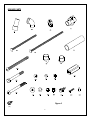
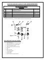
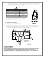
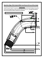
ASSEMBLY AND INSTALLATION INSTRUCTIONS CORPORATE HEADQUARTERS WESTERN SALES AND MANUFACTURING PLANT P.O. Box 400 1017 SW Berg Parkway Canby, Oregon 97013 (503) 266-2231 (503) 266-4334 www.srsmith.com 06-820 S.R. SMITH, LLC 2013 MAY14 Table of Contents Topic Page # INTRODUCTION ............................................................................................................................................................................ 2 ROGUE2 PARTS LIST ..................................................................................................................................................................... 3 TOOLS REQUIRED FOR SLIDE ASSEMBLY: .................................................................................................................................... 5 ASSEMBLY INSTRUCTIONS ........................................................................................................................................................... 7 ASSEMBLY INSTRUCTIONS FOR ON DECK MOUNTING .............................................................................................................. 13 IN-DECK MOUNTING .................................................................................................................................................................. 14 SLIDE PLUMBING INSTRUCTIONS .............................................................................................................................................. 14 MANUFACTURER’S PLACEMENT INSTRUCTIONS ....................................................................................................................... 16 ELECTRICAL BONDING................................................................................................................................................................ 18 Appendices: Left and Right CURVE FOOTPRINT......................................................................................................................... 19 INTRODUCTION DANGER – FAILURE TO FOLLOW THESE WARNINGS, INSTRUCTIONS AND THE OWNER’S MANUAL MAY RESULT IN SEROUS INJURY OR DEATH THE ROGUE2 SLIDE IS DESIGNED AND MANUFACTURED FOR INSTALLATION AND USE ON INGROUND SWIMMING POOLS ONLY. DO NOT INSTALL THE ROGUE2 SLIDE ON ABOVE GROUND POOLS, HOUSEBOATS, BOAT DOCKS, FLOATING DOCKS OR PLATFORMS, OR OTHER BODIES OF WATER SUCH AS LAKES, PONDS, RIVERS, ETC. PROPER ASSEMBLY, INSTALLATION, USE, AND SUPERVISION IS ESSENTIAL FOR PROPER OPERATION AND TO REDUCE THE RISK OF SERIOUS INJURY OR DEATH. CHECK INSIDE ALL BOXES AND PACKAGING MATERIALS FOR PARTS. BEFORE BEGINNING ASSEMBLY, READ ALL INSTRUCTIONS AND IDENTIFY PARTS USING THE FIGURES AND PARTS LISTED IN THIS DOCUMENT. IT IS CRITICAL THAT ALL PARTS BE CAREFULLY INSPECTED BY THE INSTALLER PRIOR TO INSTALLATION TO ENSURE THAT NO DAMAGE OCCURRED IN TRANSIT AND THAT A DAMAGED PART IS NOT USED. PROPER INSTALLATION CANNOT BE OVERSTRESSED, AS AN IMPROPER INSTALLATION VOIDS S.R. SMITH’S WARRANTY AND MAY AFFECT THE SAFETY OF THE USER. INSTALLER MUST GIVE TO SLIDE OWNER: ROGUE2 SLIDE INSTALLATION AND OWNER’S MANUAL, THE WARRANTY CARD, AND ANSWER ALL QUESTIIONS REGARDING SAFE AND PROPER USE AND SLIDE MAINTENACE. FOR COMPLETE SLIDE SAFETY INFORMATION REFER TO THE OWNER’S MANUAL. INSTALLED ROGUE2 STRUCTURAL & INSTALLATION CHECKLIST (INSTALLER TO REVIEW WITH SLIDE OWNER UPON COMPLETION OF SLIDE INSTALLATION) 1. 2. 3. 4. 5. INSPECT THE RUNWAY FOR VISIBLE CRACKS OR TEARS. INSPECT THE SLIDE FOR SHARP EDGES, PROTRUSIONS, CRACKS OR TEARS. INSPECT ALL FASTENERS TO MAKE SURE THEY ARE FULLY TIGHTENED. INSPECT THE LADDER FOR RIGIDITY AND ATTACHMENT. MEASURE THE FOLLOWING DIMENSIONS AND COMPARE WITH THE MANUFACTURER’S PLACEMENT INSTRUCTIONS ON PAGES 17 AND 18. MEASURE THE DEPTH OF WATER IN FRONT OF THE SLIDE EXIT. (4’-6” (1371 mm) MIN. DEPTH AT A DISTANCE OF 4’-6” (1371 mm) FROM EXIT END OF SLIDE.) MEASURE THE HEIGHT OF THE SLIDE RUNWAY EXIT ABOVE THE WATER. (20” (508 mm) MAX.) MEASURE THE DISTANCE BETWEEN THE SLIDE CENTERLINE AND THE EDGE OF OTHER POOL EQUIPMENT. 6. OBSERVE THE POSITION OF THE EXIT OF THE SLIDE AS SHOWN IN FIGURES 17, 18 AND 19 ON PAGES 17 AND 18. 2 ROGUE2 PARTS LIST Before getting started check to make sure that all of the parts listed below arrived with the S.R. Smith ROGUE2 slide. Ref # * 1 2 3 4 5 6 7 8 9 10 11 12 13 14 15 16 17 18 19 20 21 22 23 24 * PART # 05-773 05-181 05-767 05-770 05-31-151 05-31-149 01-212 6-123 6-121 05-14-111 5-149 5-137 01-210 5-237 5-248 5-250 5-145 5-151 5-139 5-156 05-31-110S 5-371 05-668 05-14-124 05-786-8 DESCRIPTION Garden Hose Adapter (ref. pg 13) 1” PVC 90 Elbow ST SCH 40 SXS Plastic Pipe Clamp for 1” SCH 40 PVC Ball Valve SCH 80 SXS ¼-20 x 6” Carriage Bolt S/S ¼-20 x 8” Carriage Bolt S/S Aluminum Handrail Spacer Nylon Handrail Connector Nylon Tube Connector 1/4 x 5/8 Flat Washer ¼” Lock Washer S/S ¼-20 Hex Nut S/S Aluminum Ladder Spacer 3/8-16 X 5" B.H.C.S. 18-8 S/S FULL-THREAD (TT) HHCS 3/8-16 X 3.5" S/S 3/8” x 3.5” Button Head Cap Screw S/S 3/8” Flat Washer S/S 3/8” Lock Washer S/S 3/8” Hex Nut S/S 3/8-16 ACORN NUT 316 S/S HIGH Crown 5/16 Hex Washer Head Tek Screw S/S Self Tapping Screw #10-16 x 1” S/S Vinyl Cap .172 ID x .5 LG. ¼” X ½” Sheet Metal Screw Hose PVC Flex, 8 ft (not shown in Figure 1) 3 QTY 1ea. 1 ea. 6 ea. 1 ea. 4 ea. 2 ea. 6 ea. 8 ea. 6 ea. 13 ea. 8 ea. 8 ea. 2 ea. 2 ea. 2 ea. 4 ea. 16 ea. 8 ea. 4 ea. 4 ea. 4 ea. 6 ea. 6 ea. 5 ea. 8 ft. ROGUE2 PARTS Figure 1 (24) 4 SLIDE DECK ANCHOR FLANGE KIT PARTS (SOLD SEPERATELY) SLIDE DECK ANCHOR FLANGE KIT (75-209-5866) 1 2 75-209-5000 05-162 3 4 5 6 7 05-14-123 04-14-111 05-14-117 01-500 5-306 Aluminum Flange Anchor 5/16 -18 UNC x 2 3/4 STUD w/ FLAT WASHER & LOCK NUT 1/4-20 UNC x 2 3/4 HHCS 1/4"ID x 5/8"OD FLAT WASHER 1/4-20 UNC HEX NYLON LOCK NUT 3/8" O.D. ALUMINUM BUSHING 3/8” O.D. Aluminum Bushing * Ref #s are shown as (#__ ) in these ASSEMBLY AND INSTALLATION INSTRUCTIONS Figure 2 TOOLS REQUIRED FOR SLIDE ASSEMBLY: PVC glue 7/32” Allen Wrench Electric Drill, Phillips Drive, ½ Hex Socket Drive Ratchet with 7/16”, 1/2" and 3/8” sockets 7/16”, 1/2” and 9/16” wrench Hammer drill with 1/4" (6 mm) masonry bit Small Level Tape 9/16” Deep Socket 3/8” (9.5 mm) Drill Bit ¼” (6 mm) Drill bit Pencil or marker Loctite® 242 Thread Locking Compound 5 4 ea. 16 ea. 4 ea. 8 ea. 4 ea. 4 ea. 16 ea. ROGUE2 SLIDE LAYOUT The purpose of this footprint is to serve as a GUIDELINE ONLY for approximate placement of the slide relative to the pool’s edge. The actual dimensions after installation may vary according to the slope of the deck and the angle that the slide is oriented relative to the pool wall. YOU MUST FOLLOW THE INSTALLATION INSTRUCTIONS AS PRINTED IN THIS MANUAL. Note: When installing the slide in the deck, all height dimensions will be reduced by at least 3 inches, or by the depth the slide is installed below deck grade. Figure 3 For SI: 1 degree = 0.017 rad, 1 inch = 25.4 mm, 1 foot = 304.8 mm ROGUE 2 right curve slide shown, left curve is mirror image of right curve. SEE APPENDICES (pg.17) for additional slide layout details. 6 ASSEMBLY INSTRUCTIONS 1) Place the slide runway upside down on a surface that will not scratch the slide. (TIP: Use flattened Rogue2 box to help protect slide from scratches during assembly.) a. Ensure the gaskets installed at the factory are still in place. Any damaged gasket should be replaced prior to assembly. b. Use Anti-Seize on all hardware pieces to prevent galling of the stainless steel. 17, 18, 19 c. Begin by installing the hardware through the outside rails of the runway. Insert a (#14) 5” Button Head Screw with a (#17) Flat Washer though each side rail as shown in Figure 4. Fasten each screw using a (#17) Flat Washer, (#18) Lock Washer, and (#19) Hex nut. Do not fully tighten at this point. 15, 17 19 18 17 17 14 d. Next, insert the hardware through the Figure 4 holes in the bottom of the runway parts. Insert a (#15) 3.5” Hex Head Screw with a (#17) Flat Washer though each hole as shown in Figure 4. Fasten each screw using a (#17) Flat Washer, (#18) Lock Washer, and (#19) Hex nut. 7 e. Go back and fully tighten the outside bolts before completely tightening the center bolts. Tighten until the plastic surfaces come into contact and are secure. Do not over tighten the hardware. 2) Insert the slide legs into the leg sockets. See Figure 5. a. The two short legs go into the front sockets nearest the slide exit. b. The shorter of the two longer legs goes into the socket on the inside curve of the slide. c. Be sure to insert the end of the legs that do not have the pre-drilled holes into the leg sockets. d. Do not attach the legs permanently at this point. e. Tape the legs to the leg sockets so that they will be held in place when turning the slide upright. Figure 5 3) Insert the top of the slide ladder all the way into the two sockets in the slide. Use clamps to temporarily hold the ladder in place while the slide is being turned upright. See Figure 6. NOTE: The top of the ladder is the end with the side rails cut square. Figure 6 Guide slots 8 4) Carefully turn the slide with the legs and ladder upright for setup. It will be necessary for two people to perform this to avoid damage to the slide. 5) Place the slide at the desired location relative to the pool wall. See MANUFACTURER’S PLACEMENT INSTRUCTIONS on pages 17 & 18. 6) Temporarily remove the clamps to make final adjustments to the ladder. a. Make sure that the slide entrance is level from side to side while maintaining a height of 77” + 1/2” (1955.8 mm + 12.7 mm) from the deck level, and a ladder angle of 15 deg. (0.262 rad) with respect to the vertical. See Figure 3 for reference. b. Reattach clamps to hold the ladder in place prior to drilling. 7) Drill two 3/8” (9.5 mm) diameter holes through each of the ladder side rails using the holes in the slide as a drill guide. See Figure 7 Level left to right And adjust clamps DRILL 3/8” BIT x4 Places 17, 16 For SI: 1 degree = 0.017 rad 17, 18, 20 Figure 7 9 8) Secure the ladder to the slide using the hardware as shown in Figure 7. Insert a (#16) 3.5” Button Head Screw with a (#17) Flat Washer though each drilled hole. Fasten each screw using a (#17) Flat Washer, (#18) Lock Washer, and (#20) Acorn Nut. 9) With the entrance way secured and the slide in relative final position. Level as close as possible the exit runway surface horizontally, from side to side, using a small level. The exit end height should be maintained at 7” (178 mm) between the bottom of the slide and the deck, see Figure 3. 10) The legs can be adjusted up and down within the leg sockets to help adjust for level. Once the slide is properly leveled the legs shall be permanently attached by drilling a 1/4" (6 mm) hole into each leg using the hole on the leg socket as a guide and fastening with a (#21) 5/16” Hex Head Washer Tek Head Screw. See Figure 8. 21 Step 3. x 4 Places Figure 8 Step 3. Step 2. 10 11) Disassemble each handrail as shown in Figure 9. Insert the two handrails into the holes on the top of the slide runway rails, and rotate so that the rails are resting in the grooves on the back side of the entrance section. Secure each handrail into the socket using a (#10) Flat Washer, a (#11) Lock Washer, and a (#12) Hex Nut. Use Loctite® 242 Thread Locking Compound on all handrail fasteners. 10 11 12 6 5 8, 7, 9, 13, 10, 11, 12 8, 7, 9, 10, 11, 12 5 8, 7, 9, 10, 11, 12 Figure 9 12) Starting with the top handrail spacer, align the top hole in the handrail with the top hole in the ladder side rail. Next, assemble the handrail spacer parts (#7), (#8) and (#9) in the order shown in Figure 9 and align it between the handrail and ladder top holes. Next, insert the (#6) 1/4-20 x 8” Carriage Bolt through the handrail and the handrail spacer parts. The (#13) Ladder spacer is to be placed in the inside channel of the ladder side rail such that the (#6) Carriage Bolt holds it in place after it is pushed completely through the ladder side rail, see Figure 10. Secure the (#6) Carriage bolt using a (#10) Flat Washer, a (#11) Lock Washer, and a (#12) Hex Nut in the order shown in Figure 9 and 10. Use Loctite® 242 Thread Locking Compound on all handrail fasteners. 11 10 11 12 Insert Spacer (13) 10, 11, 12 Figure 10 13) For the remaining two ladder spacers, align parts (#7), (#8) and (#9) between the hole in the handrail and the hole in the ladder as in step 12. Use a (#5) 1/4-20 x 6” Carriage Bolt along with a (#10) Flat Washer, a (#11) Lock Washer, and a (#12) Hex Nut to fasten the parts together as 12 shown in Figures 9 and 10. Use Loctite® 242 Thread Locking Compound on all handrail fasteners. ASSEMBLY INSTRUCTIONS FOR ON DECK MOUNTING (FOR IN-DECK MOUNTING PROCEED TO STEP 19) 14) Bond slide per local codes (see ELECTRICAL BONDING page 18). 15) Place a deck anchor flange over each end of the slide legs. 16) Using the four holes on each flange as a template (see Figure 11 below), mark the location of each hole on the deck, Next, drill a 5/16” (7.9 mm) diameter by 1-7/8” deep hole at each marked location. CAUTION: Do not drill holes larger than 5/16” (7.9 mm). Maintain drill hole straight and perpendicular for proper holding strength of anchor stud. 17) Raise the flange up the leg and secure in place while using a hammer to drive the (#28) 5/16”18UNC x 2-3/4” Anchor Stud, with a (#28) 5/16” Hex Nut on top, into the hole leaving 7/8 of an inch (22.2 mm) of the stud above the deck. Then tighten the nut until it is flush with the deck. Then, tighten the nut approximately three turns to set the anchor stud. Finally, remove the nuts. 18) Secure the four flanges with (#28) 5/16” Flat Washers, (#31) 5/16" Lock Washers and the (#28) 5/16"–18UNC Hex Nuts. 19) Using the center holes on each ladder foot as templates, mark the hole locations on the deck. Next, drill holes 5/16" (22.2 mm) diameter by 2-1/4 inches (57.1 mm) deep and secure (#28) Anchor Studs as described in 3 & 4 above. Figure 11 20) Secure the two ladder feet with (#28) 5/16” Flat Washers, (#31) lock washers, and the (#28) hex nuts. Be sure that the ladder maintains 15 degrees (0.26 radians) from vertical. 21) Drill a 1/4" (6.3 mm) diameter hole into the slide leg through the 3/8” (9.5 mm) diameter hole in the flange. Insert the (#30) 3/8” O.D. Aluminum Bushing into the hole in the deck flange and push in until it contacts the slide leg. Now insert the (#27) 1/4"-20UNC x 2-3/4” Hex Head Cap Screws and (#25) 1/4" x 5/8” Flat Washers through the bushing and in about a 1/2" (12.7 mm) into the hole in the slide leg. With the cap screw in position, drill a 1/4" hole into the slide leg through the 5/16” (7.9 mm) diameter hole in the opposite side of the deck flange. Take care 13 not to run the drill bit into the 1/4" bolt. Push the cap screw completely through the slide leg. Install the (#25) 1/4" x 5/8” Flat Washers and (#26) 1/4"-20UNC Hex Lock Nuts (see Figure 25). IN-DECK MOUNTING 22) Insert 3/8” (9.5 mm) diameter rebar (not provided) into the holes located at the bottom of each leg making sure that the rebar will be a minimum of three inches (3”) below the deck surface. 23) Bond slide per local codes (see ELECTRICAL BONDING page 18). 24) Secure the ladder so that the ladder steps are level, from side to side, and the ladder is held at 15 degrees (0.26 radians) from vertical. 25) Secure the slide to prevent the movement during the concrete pour to ensure that the slide position remains the same. 26) SUGGESTION: To ensure easy removal of concrete from legs and ladder, wax or wrap with wax paper approximately 12 inches (305 mm) above deck level. 27) Proceed with pouring the concrete deck and finish as desired. Let concrete cure per concrete manufactures directions before using slide. SLIDE PLUMBING INSTRUCTIONS 22 3 Entrance piece hose channel for plumbing Figure 12 14 28) Use a drill with a Phillips bit to fasten the (#3) Plastic Pipe Clamp to the ladder as shown below in Figure 12. The hose clamp should be attached with the top of the clamp aligned with the top of the step and the side of the clamp against the ladder side rail, See Figure 12. Place (#6) Vinyl Cap over the tip end of the screw. Repeat this step for each tread on ladder. Install the flex hose and string it through the clamps. 2 Figure 13 29) Install the (#2) PVC 90˚ Elbow fitting onto one end of the PVC flex hose using PVC glue. Next apply glue to the male end of the (#2) Elbow fitting and the female fitting that is pre-installed in the slide. Connect the (#2) Elbow fitting and hose assembly to the slide while ensuring that the elbow fitting is oriented so that the hose is aligned with the hose channel in the bottom of the slide. See Figures 12 and 13. 30) Starting with the top hose clamp, insert the PVC hose into the clamps. The clamps automatically tighten when pressure is applied pushing the hose into the clamps. 31) Apply PVC glue to one socket of the (#4) PVC Ball Valve and insert the PVC hose into the valve as shown in Figure 14. Allow the glue sufficient time to dry. The final step is joining the PVC Ball Valve to the water source. 15 Flex Hose Figure 14 4 1 Garden Hose Adapter Installation Instructions If connecting the Rogue2 water system to the pool plumbing system is not an option you may connect the water system to a garden hose by following the steps outlined below. A.) Make sure that the Rogue2 water system has been properly assembled as explained in the Rogue2 Installation Instructions. Next, apply PVC glue around the end of the garden hose adapter indicated by the arrow in Figure 15. B.) After the glue is applied quickly insert the PVC fitting into one end of PVC ball valve as shown in Figure 16. Figure 15 C.) The final step is to thread a garden hose into the PVC garden hose adapter. Figure 16 27) After connecting the water source to the ball valve, turn on water slowly to check for leaks. MANUFACTURER’S PLACEMENT INSTRUCTIONS 1) The critical dimensions for placement of the slide are as shown in Figures 17 and 18. 16 A. The slide exit runway surface shall not exceed twenty inches (20”) (508 mm) above the water surface and not less than eight inches (8”) (203 mm) above the deck/coping surface (see Figure 17). B. The slide shall be positioned so that all water flowing off the runway exit drops into the pool. C. The minimum depth of water below the exit lip of the slide shall be three feet (3’) (914 mm) and increases to four feet six inches (4’-6”) (1371 mm) at Pt. A which is a distance of four feet six inches (4’-6”) (1371 mm) from the exit lip of the slide. (See Figure 17). ENTRANCE RUNWAY SURFACE 20" MAX. EXIT DECK/COPING SURFACE WATER LEVEL 4'-6" MIN. 3' MIN. 4'-6" MIN. PLUMBLINE Pt.A 9' MIN. Figure 17 4'-6" 13'-6" MIN. For SI: 1 degree = 0.017 rad, 1 inch = 25.4 mm, 1 foot = 304.8 mm D. A minimum depth of four feet six inches (4’-6”) (1371 mm) shall be maintained at a distance of nine feet (9’) (2743 mm) along the extended centerline of the slide from Pt.A. (See Figure 17). 2) A minimum clearance area in front of the slide shall be maintained away from the coping, another slide, a diving board or a rope and float line. (See Figure 18) The minimum clearance distance on either side of the extended centerline of the slide runway shall not be less than three feet six inches (3’-6”) (1067 mm) at a point no less than two feet six inches (2’-6”) (762 mm) from the exit of the slide and extending a distance of thirteen feet six inches (13’-6”) (1445 mm) in front of the slide. (See Figure 18) 3) SLIDE PLACEMENT INSTRUCTIONS FOR INSTALLATIONS ON POOLS WITH OTHER SLIDES AND/OR DIVING BOARDS A. The minimum clearance area in front of a properly installed diving board on an inground swimming pool is a minimum distance of three feet six inches (3’-6”) (1067 mm) on either side 17 Figure 18 of the board’s centerline as shown in Figure 20. Pt.C extends a minimum distance of “C” from the tip end of the board as shown in Figure 20. The width distance “W” on either side of Pt.C is given in CHART 1 and shown in Figure 20. For SI: 1 degree = 0.017 rad, 1 inch = 25.4 mm, 1 foot = 304.8 mm CHART 1 BOARD MINIMUM CLEARANCE AREA POOL TYPE “C” DIMENSION “W” DIMENSION I 14’-6” 5’-0” II 14’-6” 6’-0” III 16’-6” 6’-0” IV 18’-6” 7’-6” V 21’-0” 7’-6” See Article 5 contained in ANSI/APSP/ICC -5 2011 STANDARD FOR RESIDENTIAL INGROUND SWIMMING POOLS and refer to Figure 3 and Table 1 for Minimum Water Envelope Dimensions AB, BC and Width at Point C. “C” DIMENSION FOR BOARD = AB + BC “W” DIMENSION FOR BOARD = WIDTH AT PT.C Figure 19 B. The minimum clearance area of a slide or diving board shall not intersect any coping or rope and float line. (See Figure 20) The minimum clearance area of a slide or diving board may intersect each other provided that they are not used simultaneously. Figure 20 ELECTRICAL BONDING If electrical bonding is required by the local governmental regulations, it shall be done in accordance with Article No. 680 of the current National Electrical Code or the local Code, whichever has jurisdiction. Five (#24) 1/4" x 1/2" Sheet Metal Screws and five (#10) 1/4" x 3/4" Flat Washers are provided for this purpose. Secure one per slide leg and one per ladder. 18 Appendices: Rogue 2 Slide Footprint (Right Curve Shown, Left Curve is Mirror Image) The purpose of this footprint is to serve as a GUIDELINE ONLY for approximate placement of the slide relative to the pool’s edge. The actual dimensions after installation may vary according to the slope of the deck and the angle that the slide is oriented relative to the pool wall. YOU MUST FOLLOW THE INSTALLATION INSTRUCTIONS AS PRINTED IN THIS MANUAL. For SI: 1 degree = 0.017 rad, 1 inch = 25.4 mm, 1 foot = 304.8 mm 19