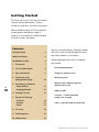
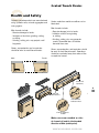
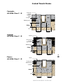
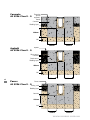
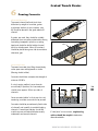
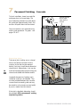
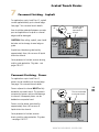
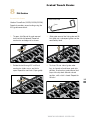
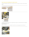
1
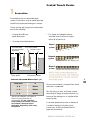
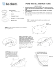
Grated Trench Drains
O
TT
OIN AIL
J
T
ION DE
NS R’S
A
P
E
EX GINE
EN
TE
RE
C
ON
C
E
AY
DD
L
ING
BE
ACO DRAIN
Site Installation Manual
Polymer Concrete Drain Systems
R
Getting Started
ACO Drain consists of a full range of modular
channels with lockable grates; Systems
include pits, end caps, and other accessories.
When installed correctly, ACO Drain products
are designed to withstand a variety of
loadings as classified by AS 3996 (standard
for access covers and grates).
Contents
Getting Started
2
Health and Safety
3
Installation Sections
4
1. Excavation
7
2. On-Site Fabrications
8
3. Pipe Connections 9
4. Connection with
Underground Piping Typical equipment necessary for installation
may include:
•
Excavating equipment
•
String-line and laser level
•
Measuring tools
•
Masonry drill, diamond holesaw,
grinder and/or saw
•
Rubber mallet
•
Concrete - 25 MPa minimum
compressive strength
•
Gloves, respirator and eye protection
10
5. Positioning of Channels
- Patty Method
- Hanging Method
11
12
6. Pouring Concrete 13
7.
14
15
15
Pavement Finishing
- Concrete
- Asphalt
- Pavers
Polymer concrete products should be handled
with care as they can be damaged by impact
from other products, or machinery.
8. Fit Grates
16
9. Final Inspections
18
10. Maintenance
19
www.acoaus.com.au
Grated Trench Drains
Health and Safety
Polymer concrete products are manufactured
using synthetic resin, mineral aggregates and
curing agents.
Grates made from metals are either cast or
fabricated.
Main hazards include:
• Abrasive damage to hands.
• Inhalation of dust from grinding, cutting, or drilling.
• Grinding, cutting, etc. may project small
fragments.
Main hazards include:
• Abrasive damage/cuts to hands.
• Inhalation of dust from grinding
or cutting.
• Grinding, cutting, etc. may generate sparks; flammable items should be removed from area.
Gloves, eye protection and a respirator
should be worn to avoid these hazards.
Male
Female
Gloves, eye protection, and respirator should
be worn to avoid these hazards. Operations
should be conducted away from areas of fire
or explosion hazard.
Female
female end
(upstream)
male end
(downstream)
Flow direction
indicator arrow
Channel sequence
number
Make sure arrows moulded on sides
of channel all point in the intended
direction of flow (outlet point).
www.acoaus.com.au
Installation Sections
An installed ACO Drain System
should incorporate the following:
• Correct grate type.
• Correct channel type and size.
• Minimum grade 25 MPa
compressive strength cement
concrete surround.
It is recommended that the cement
concrete surround be durable and
conform to minimum strength
requirements, shown in the
illustrations.
These illustrations are a guide for
average ground conditions only.
If more than one pour is cast for the
concrete surround, they must be
adequately bonded to each other.
This is for structural continuity.
Refer to www.acoaus.com.au/
install_drawings_drain.htm
for other installation scenarios.
Expansion
joint to
engineer’s
details
Concrete
AS 3996 Class A - B
Concrete
Bedding layer
100mm
Soil
100mm
Asphalt
100mm
Asphalt
AS 3996 Class A - B
Base course
Concrete
Road course
Bedding layer
100mm
Soil
Specific site conditions may
require an increase in these
dimensions or reinforcement.
100mm
Pavers
It is the customer’s responsibility
to ensure the concrete
Paving sand
encasement is designed for the Bedding layer
application.
100mm
Pavers
AS 3996 Class A - B
Concrete
If in doubt, seek further
engineering
advice.
100mm
Soil
100mm
100mm
www.acoaus.com.au
Grated Trench Drains
Concrete
AS 3996 Class C - D
Expansion
joint to
engineer’s
details
Concrete
Bedding layer
150mm
Soil
150mm
Asphalt
AS 3996 Class C - D
150mm
Asphalt
Base course
Concrete
Road course
Bedding layer
150mm
Soil
Pavers
AS 3996 Class C - D
150mm
150mm
150mm
150mm
Pavers
Paving sand
Bedding layer
Concrete
150mm
Soil
www.acoaus.com.au
Concrete
AS 3996 Class E - G
Expansion
joint to
engineer’s
details
Concrete
Bedding layer
200mm
Soil
Asphalt
AS 3996 Class E - G
200mm
200mm
200mm
200mm
200mm
200mm
Asphalt
Base course
Concrete
Road course
Bedding layer
200mm
Soil
Pavers
AS 3996 Class E - G
Pavers
Paving sand
Bedding layer
Concrete
200mm
Soil
www.acoaus.com.au
Grated Trench Drains
1
Excavation
Excavate trench to accommodate drain
system. Excavations must be made about the
centre line of proposed drainage run and pit.
Trench must be big enough to accommodate
each of the following:
A. Channel/pit width and depth dimensions.
C. For sloped and stepped systems, excavate base of trench to roughly follow fall of trench run.
B. Concrete surround dimensions.
See table below
for recommended
dimensions
ACO Drain channel
Sloped
system
Finished surface
10, 9,
8, 7,
6,
5,
4,
3
Stepped
system
x
030, 030, 030, 020, 020, 020, 010, 010
x
Neutral
system
x
Trench profile
Formwork if required
Concrete Surround Dimensions* (x)
Load Class
X
A - B
100mm
C - D
150mm
E - G
200mm
* Specific site conditions may require an increase in these dimensions or
reinforcement. It is the customer’s
responsibility to ensure the concrete
encasement is designed for the
application. Engineering advice may
be required.
010, 010, 010, 010, 010, 010, 010, 010
NOTE: Check product literature for
overall product depth. Add additional
measurement for concrete surround
from table at left.
Ensure loose material is removed from trench
and base is compacted.
Run string line, or laser, at finished surface
level along full length of proposed trench run
to ensure the drainage run is installed at the
correct grade.
In concrete pavements ensure an allowance
is made for expansion/isolation joints,
if necessary, to allow movement due to
expansion/contraction.
www.acoaus.com.au
2
On-Site Fabrications
When cutting channels and/or grates, gloves,
protective eye wear and respirator or mask
are recommended.
Cutting channels is required to form mitres,
tee junctions and non-standard lengths.
Fabrications can be completed on site.
Channels should be cut with a masonry or
diamond disc saw. Grates should be cut with
band saw, or similar, with suitable blade.
Mitres
Mitred joints are formed by cutting channels
to required angle and butting together.
For heavy duty applications, mitred grates are
not recommended. A tee joint is suggested to
give grate maximum support.
Channels mitred
at 45° angle
Channels are mitred;
grates are shown as tee joint.
Tee Junctions
Tee junctions are when an opening is cut into
the side of one channel and another channel
is butted up to this opening.
A 2-part polymer concrete repair kit
(ACO Tuffstick) or a suitable proprietary
sealant/adhesive can be used to bond cut
surfaces together, if required.
Mark area in channel wall to be removed by
butting channels together and marking profile
of interior of channel.
Edge rail should be left intact to provide
additional strength and seating for grate.
If corrosive liquids are transported in trench,
joints should be properly sealed. Ensure the
sealant/adhesive used is chemically resistant.
www.acoaus.com.au
Grated Trench Drains
3
Pipe Connections
Removal of preformed drill-outs, or cut hole:
1. Identify and mark area to be removed. Holesaw
Holesaws are available to assist with pipe
connections.
2. Remove drill-out.
90mm
99095
100mm
99120
125mm
99150
150mm
99170
To Suit Pipe Sizes
Stitch Drill
• Using approximately an 8mm
masonry drill bit stitch drill around
the preformed drill-out or marked
hole/slot. (Bracing may be required)
SDS Plus Arbour
Part Number
99200
• Using correct size diamond holesaw,
remove channel/pit wall/base to fit pipe.
(Bracing may be required).
• Remove the remaining fins using a
hammer and a sharp cold chisel.
3. A grinder may be used to dress or enlarge
hole for proper pipe or channel insertion.
4. A pipe may be fitted into hole using
proprietary sealant/adhesive. If corrosive
liquids are transported in trench, ensure
sealant or adhesive is chemically resistant.
CAUTION: Do not hammer directly on material
to make penetration or remove drill-out.
This may cause severe cracking of material
surrounding hole.
www.acoaus.com.au
4
Connection with Underground Piping
Channels may be connected directly to
underground piping via:
1. End cap outlets (horizontal outlet).
4. Universal Junction Pit
2. Vertical drill-outs (penetrations on underside of channel).
Cut out guides are featured on sides of
in-line pits and the universal junction pit for
channel connection at depths and widths
corresponding to different channel systems.
Using a masonry or diamond disc saw, cut
at required channel depth and remove wall.
Smooth edges with grinder and seal joint with
flexible sealant.
10
3. In-line pit.
www.acoaus.com.au
Grated Trench Drains
5
Positioning of Channels
Start with outlet point. Ensure string-line, or
laser is set at top edge of required channel
height.
For KlassikDrain K100 System - K31 to K60
channels are supplied in two pieces, a base
channel and an extension piece. Install base
channel at 180mm below the required height
then position the extension piece on top of
the base channel.
Common methods of positioning channels
include: 1. Patty Method
2. Hanging Method
Male
Female
As per table (pg. 7)
d) Lower channel vertically onto patties’ and
position to correct height and alignment
ensuring ‘tight’ connection to previous
channel.
Concrete key
1. Patty Method
a) Set pit (or outlet channel) on bed of concrete
to required height (see page 7 for concrete
dimensions). Connect and seal outlet pipe.
b) Using stiff/wet mix concrete, create ‘patties’ at
intervals to support channels. Allow two patties
per channel, spaced such that no concrete
material is trapped in the joint, creating gaps.
Note: Patties should be sized to provide
required concrete surround (see page 7).
c) If channels are to be sealed, roughen
ends and use a flexible sealant - check
chemical compatability, if required.
Avoid concrete/dirt at joint
e) Add concrete on top of ‘patty’ to cover
concrete ‘keys’ on side of channel - this
prevents movement, or floating, during
concrete pour.
f) Continue to lay channels until end of run
or next pit is reached.
IN
RA
OD
AC
AC
RA
OD
AC
IN
IN
RA
OD
Work away from outlet
www.acoaus.com.au
11
5
Positioning of Channels - Hanging Method
Hanging is often used in retrofit installations
as existing slab provides good anchor for
supports. Alternatively, formwork can be
used for support.
2. Hanging Method - PowerDrain Only
S100K, S200K, S300K, will require M10
- 1.5 x 120mm bolts to screw into widgets
in edge rail of channel. This allows the bolt
to pass through the spacers, 2 x 4’s and
into widget nut.
Widgets in edge rail
a) Cut 2 x 4’s of appropriate width to span
excavated trench or formwork
(minimum 2 per channel - S200K, S300K
will require 3 - 4 per channel). Cut
‘spacers’ to ‘lift’ supports above finished
level - one per hanging 2 x 4
12
b) Drill two 16mm diameter holes aligned
with the widgets in the 2 x 4’s and
spacers.
c) Using M10 - 1.5 x 120mm bolts with
washers, bolt 2 x 4 and spacer to
channel - do not overtighten. If using
torque wrench do not set higher than
20 Nm.
2x4
supports
Spacer
Anchoring
fasteners
to prevent floating
Retrofit installation
Spacers allow
concrete surface
finishing
d) Lower channels into excavated trench,
adjust to required position and height.
Packing material may be required
beneath 2 x 4’s to achieve required height
and to ensure channels are level.
e) If channels are to be sealed, roughen
ends and use a flexible sealant - check
chemical compatability, if required.
f) Nail or bolt 2 x 4 supports securely to
slab/formwork. This ensures channels
are held securely during concrete pour.
Saw cut
2 x 4 (anchoring fasteners
to prevent floating)
Finished height
New installation
www.acoaus.com.au
Grated Trench Drains
6
Pouring Concrete
Channel Bracing
To prevent channel wall and joints from
distortion by weight of concrete, grates
or plywood sections (cut to create a snug
fit) should be placed in the grate rebate of
channel.
If grates are used, they should be suitably
protected from concrete contamination during
concreting (wrapped in plastic or masking
tape) and should be laid to bridge channel
joints to aid alignment. Shims (or washers)
should be placed along one side to maintain a
clearance gap.
Shim
Concrete Pour
To prevent concrete from filling channel body,
cover open areas with plywood or similar.
(Bracing should suffice).
Concrete should have compressive strength of
minimum 25 MPa.
If using hanging method, once channels
are securely in position, first concrete pour
should come approx. 50mm up sides of
channels.
Second
pour
First
pour
Once concrete ‘patties’ or first pour has set,
remaining concrete surround can be poured.
Concrete should be poured evenly (both sides
of channel) and carefully to avoid dislodging
channels. A wand type vibrator should be
used to ensure concrete distributes evenly
underneath and around channels.
If ‘cold joints’ are a concern, engineering
advice should be sought to determine
alternative details.
www.acoaus.com.au
13
7
Pavement Finishing - Concrete
To finish installation, trowel concrete flat
and taper down to channel edge. The
top of adjacent pavement must be above
the grate level (approximately 3mm), this
ensures all liquids drain into the channel.
Approx.
45°
3mm
Grate
Finished concrete
to have slight
slope down to
channel
Once concrete has set, remove bracing
and/or grate protection. Fit grates - see
pages 16 & 17.
Concrete
14
Expansion joints
Transverse joints (cutting across channel
haunch and base) to prevent surface
cracking in the slab may be required.
Ideally, such joints should be positioned at
channel joints. Alternatively, a cut may be
made at the appropriate location along the
channel and sealed with flexible sealant.
Longitudinal expansion/isolation joints
should be continuous and flexible. They
must be provided between the concrete
surround and surrounding slab and may
be varied to suit concrete surround width
by up to a metre from the channel.
Flexible material
at channel joint Expansion
joint
Original slab
Transverse Joint
If the joint is dowelled, debonding should
be provided. ACO recommends seeking
engineering advice.
www.acoaus.com.au
Grated Trench Drains
7
Pavement Finishing - Asphalt
For applications up to Load Class D, asphalt
can be applied directly up to channel edge.
See page 7 for concrete haunch details.
Approx.
45°
Area should be protected between concrete
pour and application of asphalt as channel
edge could be damaged.
CAUTION: When rolling asphalt, care should
be taken not to damage channel edge or
grate.
3mm
Grate
Finished asphalt
to have slight
slope down to
channel
Base
Course
Asphalt must be above grate level by
approximately 3mm, this ensures all liquids
drain into channel.
Concrete
Once pavement is finished, remove bracing
and/or grate protection. Fit grates - see
pages 16 & 17.
Pavement Finishing - Pavers
For applications up to Load Class D,
pavers can be installed up to channel edge.
See page 7 for concrete haunch details.
Pavers adjacent to channel MUST be fully
bonded to concrete haunch. This prevents
movement of pavers and possible damage
to channel. Subsequent pavers can be
bedded on compacted sand.
15
First course bonded
to concrete haunch
3mm
Grate
Pavers must be above grate level by
approximately 3mm, this ensures all
liquids drain into channel.
Once pavement is finished, remove
bracing and/or grate protection. Fit grates
- see pages 16 & 17.
Concrete
www.acoaus.com.au
8
Fit Grates
Grate removal tool
QuickLok Grates
Used on KlassikDrain grates, QuickLok
provides secure boltless locking, which is
quick to remove/replace for maintenance and
cleaning.
QuickLok bars
1. Locate locking bar in the channel wall recesses by rotating clockwise.
K100
K200
K300
2. K100 - Use hammer to tap bar into
place, so that the serrated ends grip in recess. K200/K300 - Push plastic clips
forward to lock bar into position.
4. To remove grate, insert grate removal
tool under grate bar and pull up sharply. Once first grate is removed, remaining grates can be removed
by hand. Grip end of grate and lift
sharply (use gloves).
16
3. To install QuickLok grate, align stud
directly over locking bar. Push down or
stand on grate until it clicks into position.
5. K100 - To remove bar, insert screwdriver
into holes at ends of bar and lever back
serrated end, which should then come free.
K200/K300 - Push plastic clips back to
unlock, rotate bar free.
www.acoaus.com.au
Grated Trench Drains
8
Fit Grates
PowerLok Grates
Used on PowerDrain (S100K/S200K/S300K),
PowerLok provides secure locking using the
ACO grate removal tool.
Grate removal tool
13m
m
1. To open: slip flat end of grate removal
tool into the slot between PowerLok mechanism and edge rail as shown.
3. Slide grate removal tool into grate and lift
first grate out, subsequent grates can be
removed by hand.
2. Rotate the tool through 90˚ until lock
mechanism slides across and clicks
open. Repeat for each lock (2 per grate).
4. To close: Fit one side of grate under
lugs in channel rail and lower grate into
position. Use hook on grate removal tool
to push the clip back towards closed
position, until a click is heard. Repeat for
all locks.
17
www.acoaus.com.au
9
Final Inspections
Final Inspections
1. Remove any debris in system and grate rebate. Ensure outlet pipes are
clear.
2. Install rubbish baskets in pits, if required.
3. Flush trench run to check for pipe work blockages, unblock if necessary.
4. Empty rubbish baskets and clean out pipe connections, if necessary.
Replace rubbish baskets.
5. Install grates in proper position ensuring they are securely locked down
(pages 16 & 17).
Drainage system is now ready for use.
18
www.acoaus.com.au
Grated Trench Drains
10
Maintenance
Maintenance
Regular inspections of trench drain system are recommended.
Frequency will depend on local conditions and environment, but should
be at least annually.
Inspections should cover:
• Grates and locking devices
• Pits and rubbish baskets
• Concrete surround and adjacent paving
All items should be inspected for damage, blockage or movement.
Compare with site drawings if necessary.
1. Remove grates - see pages 16 & 17.
2. Remove debris from channel.
3. Flush channels with water or high pressure washer.
4. Repair damaged surfaces, if necessary, with an appropriate ACO
repair kit.
5. Renew joint seals as required.
6. Empty rubbish baskets and clean out pipe connections.
7. Re-install rubbish baskets.
8. Re-install grates, ensuring they are locked in place.
Systems with grates that have wide slots may be cleaned with the use
of pressured water applied through the grate — debris will be washed
to pits for removal. (Empty and replace rubbish basket).
www.acoaus.com.au
19
Other ACO Product Lines
ACO Cablemate
A range of electrical and
communication cable jointing
pits and surface ducting
systems.
ACO DRAIN
A range of grated trench drainage
systems and pits made from ‘Polycrete’
polymer concrete. Grates are available
in various materials and finishes for all
loadings.
ACO Access
A range of ductile iron,
galvanised steel and composite
access covers in a wide range
of sizes and configurations from
single to large multi-part units.
ACO Stainless
A range of high performance
stainless steel drainage
channels, grates, floor drains
and pipes for hygiene and
aesthetic applications.
ACO Sport
A complete range of surface
drainage systems and ancillary
products for sport fields,
running tracks and stadiums.
ACO Home
An range of economical domestic
drainage products, ideal for
homes, gardens and landscaped
areas.
ACO Polycrete Pty Ltd
ABN 65 050 102 942
www.acoaus.com.au
Sales Hotline
Telephone 1 300 765 226
Facsimile + 61 2 4747 4040
Email [email protected]
Technical Services Hotline
Email [email protected]
NSW and Head Office
134-140 Old Bathurst Rd
Emu Plains NSW 2750
Australia
Telephone +61 2 4747 4000
Facsimile + 61 2 4747 4060
QLD Office
467 Tufnell Road
Banyo QLD 4014
Telephone (07) 3267 8700
Facsimile (07) 3267 8711
[email protected]
VIC Office
9 Overseas Drive
Noble Park VIC 3174
Telephone (03) 9795 3666
Facsimile (03) 9795 6444
[email protected]
South Australia
Telephone 1300 765 226
[email protected]
Western Australia
Telephone 1300 765 226
[email protected]
Northern Territory
Telephone 1300 765 226
[email protected]
© March 2008 ACO Polycrete Pty Ltd.
All reasonable care has been taken in compiling the information in this
document. All recommendations and suggestions on the use of ACO products are made without guarantee since
the conditions of use are beyond the control of the Company. It is the customer’s responsibility to ensure that
each product is fit for its intended purpose and that the actual conditions of use are suitable. ACO Polycrete Pty
Ltd reserves the right to amend products and specifications without notice.