1
Cat. No. I514-E1-2
USER’S MANUAL
OMNUC U
SERIES
MODELS R88M-Ujjj15j/-Ujjj30j
(AC Servo Motors)
MODELS R88D-UTj
(AC Servo Drivers)
AC SERVO MOTORS/DRIVERS
Thank you for choosing this OMNUC U-series product. Proper use and handling
of the product will ensure proper product performance, will length product life, and
may prevent possible accidents.
Please read this manual thoroughly and handle and operate the product with care.
NOTICE
1. This manual describes the functions of the product and relations with other products. You should assume that anything not described in this manual is not possible.
2. Although care has been given in documenting the product, please contact your
OMRON representative if you have any suggestions on improving this manual.
3. The product contains dangerous high voltages inside. Turn off the power and wait
for at least five minutes to allow power to discharge before handling or working with
the product. Never attempt to disassemble the product.
4. We recommend that you add the following precautions to any instruction manuals
you prepare for the system into which the product is being installed.
S Precautions on the dangers of high-voltage equipment.
S Precautions on touching the terminals of the product even after power has been
turned off. (These terminals are live even with the power turned off.)
5. Specifications and functions may be changed without notice in order to improve
product performance.
6. Positive and negative rotation of AC Servo Motors described in this manual are
defined as looking at the end of the output shaft of the motor as follows: counterclockwise rotation is positive and clockwise rotation is negative.
7. Do not perform withstand-voltage or other megameter tests on the product. Doing
so may damage internal components.
8. Servo Motors and Servo Drivers have a finite service life. Be sure to keep replacement products on hand and to consider the operating environment and other conditions affecting the service life.
9. The OMNUC UTj can control two groups of Servomotor models (i.e., 1,500-r/min
and 3,000-r/min). Refer to the following for the descriptions of the 1,500-r/min and
3,000-r/min models.
S 1,500-r/min models: R88M-Ujjj15j-jS1, the rated number of revolutions
of which is 1,500 per minute.
S 3,000-r/min models: R88M-Ujjj30j-j, the rated number of revolutions of
which is 3,000 per minute.
Be sure to check the model that will be used before reading this manual.
Items to Check After Unpacking
Check the following items after removing the product from the package:
S Has the correct product been delivered (i.e., the correct model number and specifications)?
S Has the product been damaged in shipping?
S Are any screws or bolts loose?
Notice:
OMRON products are manufactured for use according to proper procedures by a qualified
operator and only for the purposes described in this manual.
The following conventions are used to indicate and classify precautions in this manual.
Always heed the information provided with them. Failure to heed precautions can result in
injury to people or damage to property.
!
DANGER
Indicates an imminently hazardous situation which, if not avoided, will result in death
or serious injury.
!
WARNING
Indicates a potentially hazardous situation which, if not avoided, could result in death
or serious injury.
! Caution
Indicates a potentially hazardous situation which, if not avoided, may result in minor
or moderate injury, or property damage.
OMRON Product References
All OMRON products are capitalized in this manual. The word “Unit” is also capitalized when
it refers to an OMRON product, regardless of whether or not it appears in the proper name
of the product.
The abbreviation “Ch,” which appears in some displays and on some OMRON products,
often means “word” and is abbreviated “Wd” in documentation in this sense.
The abbreviation “PC” means Programmable Controller and is not used as an abbreviation
for anything else.
Visual Aids
The following headings appear in the left column of the manual to help you locate different
types of information.
Note Indicates information of particular interest for efficient and convenient operation of the product.
Ó OMRON, 1996
All rights reserved. No part of this publication may be reproduced, stored in a retrieval system, or transmitted, in any form, or by any means, mechanical, electronic, photocopying,
recording, or otherwise, without the prior written permission of OMRON.
No patent liability is assumed with respect to the use of the information contained herein.
Moreover, because OMRON is constantly striving to improve its high-quality products, the
information contained in this manual is subject to change without notice. Every precaution
has been taken in the preparation of this manual. Nevertheless, OMRON assumes no
responsibility for errors or omissions. Neither is any liability assumed for damages resulting
from the use of the information contained in this publication.
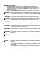
General Warnings
Observe the following warnings when using the OMNUC Servomotor and Servo Driver.
This manual may include illustrations of the product with protective covers removed in order
to describe the components of the product in detail. Make sure that these protective covers
are on the product before use.
Consult your OMRON representative when using the product after a long period of storage.
!
WARNING
Always connect the frame ground terminals of the Servo Driver and the Servomotor
to a class-3 ground (to 100 W or less). Not connecting to a class-3 ground may result
in electric shock.
!
WARNING
Do not touch the inside of the Servo Driver. Doing so may result in electric shock.
!
WARNING
Do not remove the front cover, terminal covers, cables, Parameter Units, or optional
items while the power is being supplied. Doing so may result in electric shock.
!
WARNING
Installation, operation, maintenance, or inspection must be performed by authorized
personnel. Not doing so may result in electric shock or injury.
!
WARNING
Wiring or inspection must be performed at least 5 minutes after turning off the power
supply. Doing so may result in electric shock.
!
WARNING
Do not damage, press, or put excessive stress or heavy objects on the cables. Doing
so may result in electric shock.
!
WARNING
Do not touch the rotating parts of the Servomotor under operation. Doing so may
result in injury.
!
WARNING
Do not modify the product. Doing so may result in injury or damage to the product.
! Caution
Use the Servomotors and Servo Drivers in a specified combination. Doing so may
result in fire or damage to the products.
! Caution
Do not store or install in the following places. Doing so may result in fire or damage to
the Product.
S Locations subject to direct sunlight.
S Locations subject to temperatures or humidity outside the range specified in the
specifications.
S Locations subject to condensation as the result of severe changes in temperature.
S Locations subject to corrosive or flammable gases.
S Locations subject to dust (especially iron dust) or salts.
S Locations subject to shock or vibration.
S Locations subject to exposure to water, oil, or chemicals.
! Caution
Do not touch the Servo Driver radiator or Servomotor while the power is being supplied or soon after the power is turned off. Doing so may result in a skin burn due to
the hot surface.
Storage and Transportation Precautions
! Caution
Do not hold by the cables or motor shaft while transporting the product. Doing so
may result in injury or malfunction.
! Caution
Do not place any load exceeding the figure indicated on the product. Doing so may
result in injury or malfunction.
! Caution
Use the motor eye-bolts only for transporting the Motor. Using them for transporting
the machinery may result in injury or malfunction.
Installation and Wiring Precautions
! Caution
Do not step on or place a heavy object on the product. Doing so may result in injury.
! Caution
Do not cover the inlet or outlet ports and prevent any foreign objects from entering
the product. Doing so may result in fire.
! Caution
Be sure to install the product in the correct direction. Not doing so may result in malfunction.
! Caution
Provide the specified clearances between the Servo Driver and the control panel or
with other devices. Not doing so may result in fire or malfunction.
! Caution
Do not apply any strong impact. Doing so may result in malfunction.
! Caution
Be sure to wire correctly and securely. Not doing so may result in motor runaway,
injury, or malfunction.
! Caution
Be sure that all the mounting screws, terminal screws, and cable connector screws
are tightened to the torque specified in the relevant manuals. Incorrect tightening
torque may result in malfunction.
! Caution
Use crimp terminals for wiring. Do not connect bare stranded wires directly to terminals. Connection of bare stranded wires may result in burning.
! Caution
Always use the power supply voltage specified in the User’s Manual. An incorrect
voltage may result in malfunction or burning.
! Caution
Take appropriate measures to ensure that the specified power with the rated voltage
and frequency is supplied. Be particularly careful in places where the power supply
is unstable. An incorrect power supply may result in malfunction.
! Caution
Install external breakers and take other safety measures against short-circuiting in
external wiring. Insufficient safety measures against short-circuiting may result in
burning.
! Caution
Provide an appropriate stopping device on the machine side to secure safety. (A
holding brake is not a stopping device for securing safety.) Not doing so may result in
injury.
! Caution
Provide an external emergency stopping device that allows an instantaneous stop of
operation and power interruption. Not doing so may result in injury.
! Caution
Take appropriate and sufficient countermeasures when installing systems in the following locations:
S Locations subject to static electricity or other forms of noise.
S Locations subject to strong electromagnetic fields and magnetic fields.
S Locations subject to possible exposure to radioactivity.
S Locations close to power supplies.
Operation and Adjustment Precautions
! Caution
Check the newly set parameters for proper execution before actually running them.
Not doing so may result in equipment damage.
! Caution
Do not make any extreme adjustments or setting changes. Doing so may result in
unstable operation and injury.
! Caution
Separate the Servomotor from the machine, check for proper operation, and then
connect to the machine. Not doing so may cause injury.
! Caution
When an alarm occurs, remove the cause, reset the alarm after confirming safety,
and then resume operation. Not doing so may result in injury.
! Caution
Do not come close to the machine immediately after resetting momentary power
interruption to avoid an unexpected restart. (Take appropriate measures to secure
safety against an unexpected restart.) Doing so may result in injury.
! Caution
Do not use the built-in brake of the Servomotor for ordinary braking. Doing so may
result in malfunction.
Maintenance and Inspection Precautions
!
WARNING
! Caution
Do not attempt to disassemble, repair, or modify any Units. Any attempt to do so may
result in malfunction, fire, or electric shock.
Resume operation only after transferring to the new Unit the contents of the data
required for operation. Not doing so may result in an unexpected operation.
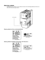
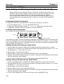
Warning Labels
Warning labels are pasted on the product as shown in the following illustration. Be sure to
follow the instructions given there.
Warning labels
Warning Labels for Non-conforming Models
Warning label 2
Warning label 1
Warning Labels for Models Conforming to EC Directives
Warning label 2
Warning label 1
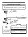
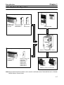
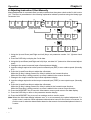
VISUAL INDEX
For users who wish to operate as quickly as possible.
- The following portions of this manual provide the minimum information required for operation.
Be sure you fully understand at least the information in these portions before attempting operation.
Chapter 2 System Design and Installation, and sections 3-1, 3-2, 3-3, and 3-4 of Chapter 3
Operation.
Instructions for jog operation using a Parameter Unit are provided in 3-4.
SYSMAC C/CV
Programmable Controller
Position Control Unit
C500-NC222-E
Motion Control Units
CV500-MC221/421
C200H-MC221
Analog input
Pulse train input
Controller Connecting Cable
Chapter 5: 5-3-1
SYSMAC C/CV
Programmable Controller
SYSMAC C200HX/HG/HE
Programmable Controller
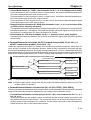
OMNUC U is a series of fully
digital AC servo drivers built
on advanced OMRON software servo technology. It provides high performance, a
sensitive man-machine interface, and economy.
Position Control Units
3G2A5-NC111-EV1
C500-NC211
Position Control Units
C200H-NC112
C200H-NC211
C200HW-NC113
C200HW-NC213
C200HW-NC413
Setting Functions
- Using Parameter Unit:
- Setting, checking setup parameters:
- Important setup parameters:
- Setting, checking user parameters
- Important user parameters
Chapter 3, section 3-1-3
Chapter 3, section 3-3-1
Chapter 3, section 3-3-1
Chapter 3, section 3-3-2
Chapter 3, section 3-3-3
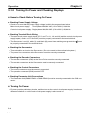
Adjustments and Troubleshooting
- Making adjustments:
Chapter 3, section 3-5
- Using displays:
Chapter 4, section 4-2
- Using monitor outputs:
Chapter 4, section 4-3
- Protections and diagnostic functions:Chapter 4, section 4-4
OMNUC U Series
Parameter Units
Operation Method
Chapter 3: 3-1, 3-2, 3-3
OMNUC U-Series AC Servo Driver
I/O Operations
Chapter 5: 5-1-3
Cable Specifications
Chapter 5: 5-3-2, 5-3-3
Motor Specifications
Chapter 5: 5-2
OMNUC U-series AC Servomotor
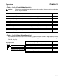
Table of Contents
Chapter 1. Introduction . . . . . . . . . . . . . . . . . . . . . . . . . . . . . . . . . . . . . 1-1
1-1
1-2
1-3
1-4
Features . . . . . . . . . . . . . . . . . . . . . . . . . . . . . . . . . . . . . . . . . . . . . . . . . . . . . . . . . . . . . . . . . . .
System Configuration . . . . . . . . . . . . . . . . . . . . . . . . . . . . . . . . . . . . . . . . . . . . . . . . . . . . . . . .
Servo Driver Nomenclature . . . . . . . . . . . . . . . . . . . . . . . . . . . . . . . . . . . . . . . . . . . . . . . . . . . .
Applicable Standards and Models . . . . . . . . . . . . . . . . . . . . . . . . . . . . . . . . . . . . . . . . . . . . . . .
1-2
1-7
1-8
1-9
Chapter 2. System Design and Installation. . . . . . . . . . . . . . . . . . . . . . 2-1
2-1 Installation . . . . . . . . . . . . . . . . . . . . . . . . . . . . . . . . . . . . . . . . . . . . . . . . . . . . . . . . . . . . . . . . .
2-1-1 External Dimensions (Unit: mm) . . . . . . . . . . . . . . . . . . . . . . . . . . . . . . . . . . . . . . . . .
2-1-2 Installation Conditions . . . . . . . . . . . . . . . . . . . . . . . . . . . . . . . . . . . . . . . . . . . . . . . . .
2-2 Wiring and Connections (Models Not Conforming to Standards) . . . . . . . . . . . . . . . . . . . . . .
2-2-1 Connecting OMRON Servo Controllers . . . . . . . . . . . . . . . . . . . . . . . . . . . . . . . . . . . .
2-2-2 Wiring Servo Drivers . . . . . . . . . . . . . . . . . . . . . . . . . . . . . . . . . . . . . . . . . . . . . . . . . .
2-2-3 Wiring for Noise Resistance . . . . . . . . . . . . . . . . . . . . . . . . . . . . . . . . . . . . . . . . . . . . .
2-2-4 Peripheral Device Connection Examples . . . . . . . . . . . . . . . . . . . . . . . . . . . . . . . . . . .
2-3 Wiring and Connections (Models Conforming to EC Directives) . . . . . . . . . . . . . . . . . . . . . .
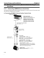
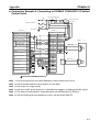
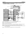
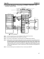
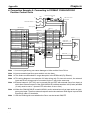
2-3-1 Connecting OMRON Servo Controllers . . . . . . . . . . . . . . . . . . . . . . . . . . . . . . . . . . . .
2-3-2 Wiring Servo Drivers . . . . . . . . . . . . . . . . . . . . . . . . . . . . . . . . . . . . . . . . . . . . . . . . . .
2-3-3 Wiring Conditions Satisfying EMC Directives . . . . . . . . . . . . . . . . . . . . . . . . . . . . . .
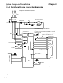
2-3-4 Peripheral Device Connection Examples . . . . . . . . . . . . . . . . . . . . . . . . . . . . . . . . . . .
2-2
2-2
2-17
2-24
2-24
2-26
2-30
2-37
2-38
2-38
2-40
2-43
2-52
Chapter 3. Operation . . . . . . . . . . . . . . . . . . . . . . . . . . . . . . . . . . . . . . . 3-1
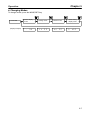
3-1 Beginning Operation . . . . . . . . . . . . . . . . . . . . . . . . . . . . . . . . . . . . . . . . . . . . . . . . . . . . . . . . .
3-1-1 Operational Procedure . . . . . . . . . . . . . . . . . . . . . . . . . . . . . . . . . . . . . . . . . . . . . . . . .
3-1-2 Turning On Power and Checking Displays . . . . . . . . . . . . . . . . . . . . . . . . . . . . . . . . .
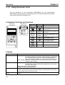
3-1-3 Using Parameter Units . . . . . . . . . . . . . . . . . . . . . . . . . . . . . . . . . . . . . . . . . . . . . . . . .
3-2 System Check Mode (Cn-00) . . . . . . . . . . . . . . . . . . . . . . . . . . . . . . . . . . . . . . . . . . . . . . . . . .
3-3 Function Settings . . . . . . . . . . . . . . . . . . . . . . . . . . . . . . . . . . . . . . . . . . . . . . . . . . . . . . . . . . . .
3-3-1 Setting and Checking Setup Parameters (Cn-01, 02) . . . . . . . . . . . . . . . . . . . . . . . . . .
3-3-2 Setting and Checking User Parameters (Cn-03 to 2d) . . . . . . . . . . . . . . . . . . . . . . . . .
3-3-3 Important User Parameters . . . . . . . . . . . . . . . . . . . . . . . . . . . . . . . . . . . . . . . . . . . . . .
3-3-4 Setting Internal Speed Control . . . . . . . . . . . . . . . . . . . . . . . . . . . . . . . . . . . . . . . . . . .
3-3-5 Switching Control Mode . . . . . . . . . . . . . . . . . . . . . . . . . . . . . . . . . . . . . . . . . . . . . . . .
3-3-6 Soft Start Function . . . . . . . . . . . . . . . . . . . . . . . . . . . . . . . . . . . . . . . . . . . . . . . . . . . .
3-3-7 Electronic Gear Function (Position Control) . . . . . . . . . . . . . . . . . . . . . . . . . . . . . . . .
3-3-8 Encoder Dividing Function . . . . . . . . . . . . . . . . . . . . . . . . . . . . . . . . . . . . . . . . . . . . . .
3-3-9 Bias Function (Position Control) . . . . . . . . . . . . . . . . . . . . . . . . . . . . . . . . . . . . . . . . .
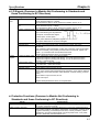
3-3-10 Torque Limit Function (Position Control, Speed Control, Torque Control) . . . . . . . .
3-3-11 Speed Limit Function (Torque Control) . . . . . . . . . . . . . . . . . . . . . . . . . . . . . . . . . . . .
3-3-12 Torque Feed-forward Function (Speed Control) . . . . . . . . . . . . . . . . . . . . . . . . . . . . .
3-3-13 Brake Interlock (for Motors With Brakes) . . . . . . . . . . . . . . . . . . . . . . . . . . . . . . . . . .
3-4 Trial Operation . . . . . . . . . . . . . . . . . . . . . . . . . . . . . . . . . . . . . . . . . . . . . . . . . . . . . . . . . . . . . .
3-5 Making Adjustments . . . . . . . . . . . . . . . . . . . . . . . . . . . . . . . . . . . . . . . . . . . . . . . . . . . . . . . . .
3-5-1 Auto-tuning . . . . . . . . . . . . . . . . . . . . . . . . . . . . . . . . . . . . . . . . . . . . . . . . . . . . . . . . . .
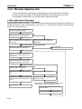
3-5-2 Manually Adjusting Gain . . . . . . . . . . . . . . . . . . . . . . . . . . . . . . . . . . . . . . . . . . . . . . .
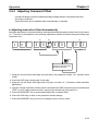
3-5-3 Adjusting Command Offset . . . . . . . . . . . . . . . . . . . . . . . . . . . . . . . . . . . . . . . . . . . . .
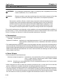
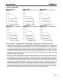
3-6 Regenerative Energy Absorption . . . . . . . . . . . . . . . . . . . . . . . . . . . . . . . . . . . . . . . . . . . . . . . .
3-6-1 Calculating Regenerative Energy . . . . . . . . . . . . . . . . . . . . . . . . . . . . . . . . . . . . . . . . .
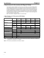
3-6-2 Servo Driver Absorbable Regenerative Energy . . . . . . . . . . . . . . . . . . . . . . . . . . . . . .
3-6-3 Absorption of Regenerative Energy by Servo Drivers
with External Regenerative Resistors . . . . . . . . . . . . . . . . . . . . . . . . . . . . . . . . . . . . . .
3-3
3-3
3-4
3-6
3-9
3-10
3-10
3-14
3-20
3-21
3-26
3-28
3-30
3-31
3-32
3-33
3-35
3-36
3-37
3-40
3-42
3-42
3-44
3-51
3-53
3-53
3-55
3-56
Table of Contents
Chapter 4. Application . . . . . . . . . . . . . . . . . . . . . . . . . . . . . . . . . . . . . . 4-1
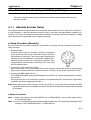
4-1 Absolute Encoder Setup and Battery Changes . . . . . . . . . . . . . . . . . . . . . . . . . . . . . . . . . . . . .
4-1-1 Absolute Encoder Setup . . . . . . . . . . . . . . . . . . . . . . . . . . . . . . . . . . . . . . . . . . . . . . . .
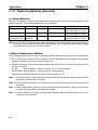
4-1-2 Replacing Batteries [Absolute] . . . . . . . . . . . . . . . . . . . . . . . . . . . . . . . . . . . . . . . . . . .
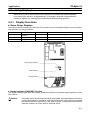
4-2 Using Displays . . . . . . . . . . . . . . . . . . . . . . . . . . . . . . . . . . . . . . . . . . . . . . . . . . . . . . . . . . . . . .
4-2-1 Display Functions . . . . . . . . . . . . . . . . . . . . . . . . . . . . . . . . . . . . . . . . . . . . . . . . . . . . .
4-2-2 Status Display Mode . . . . . . . . . . . . . . . . . . . . . . . . . . . . . . . . . . . . . . . . . . . . . . . . . . .
4-2-3 Monitor Mode . . . . . . . . . . . . . . . . . . . . . . . . . . . . . . . . . . . . . . . . . . . . . . . . . . . . . . . .
4-2-4 Checking Servomotor Parameters . . . . . . . . . . . . . . . . . . . . . . . . . . . . . . . . . . . . . . . .
4-3 Using Monitor Output . . . . . . . . . . . . . . . . . . . . . . . . . . . . . . . . . . . . . . . . . . . . . . . . . . . . . . . .
4-4 Protective and Diagnostic Functions . . . . . . . . . . . . . . . . . . . . . . . . . . . . . . . . . . . . . . . . . . . . .
4-4-1 Alarm Displays and Alarm Code Outputs . . . . . . . . . . . . . . . . . . . . . . . . . . . . . . . . . .
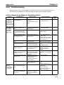
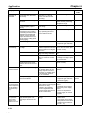
4-4-2 Troubleshooting . . . . . . . . . . . . . . . . . . . . . . . . . . . . . . . . . . . . . . . . . . . . . . . . . . . . . .
4-5 Periodic Maintenance . . . . . . . . . . . . . . . . . . . . . . . . . . . . . . . . . . . . . . . . . . . . . . . . . . . . . . . .
4-3
4-3
4-4
4-5
4-5
4-8
4-9
4-11
4-12
4-15
4-15
4-19
4-24
Chapter 5. Specifications . . . . . . . . . . . . . . . . . . . . . . . . . . . . . . . . . . . . 5-1
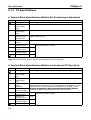
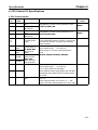
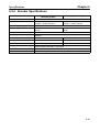
5-1 Servo Driver Specifications . . . . . . . . . . . . . . . . . . . . . . . . . . . . . . . . . . . . . . . . . . . . . . . . . . . .
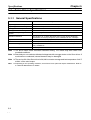
5-1-1 General Specifications . . . . . . . . . . . . . . . . . . . . . . . . . . . . . . . . . . . . . . . . . . . . . . . . .
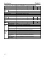
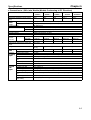
5-1-2 Performance Specifications . . . . . . . . . . . . . . . . . . . . . . . . . . . . . . . . . . . . . . . . . . . . .
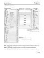
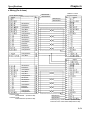
5-1-3 I/O Specifications . . . . . . . . . . . . . . . . . . . . . . . . . . . . . . . . . . . . . . . . . . . . . . . . . . . . .
5-1-4 Parameters . . . . . . . . . . . . . . . . . . . . . . . . . . . . . . . . . . . . . . . . . . . . . . . . . . . . . . . . . . .
5-2 Servomotor Specifications . . . . . . . . . . . . . . . . . . . . . . . . . . . . . . . . . . . . . . . . . . . . . . . . . . . . .
5-2-1 General Specifications . . . . . . . . . . . . . . . . . . . . . . . . . . . . . . . . . . . . . . . . . . . . . . . . .
5-2-2 Performance Specifications . . . . . . . . . . . . . . . . . . . . . . . . . . . . . . . . . . . . . . . . . . . . .
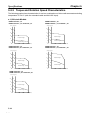
5-2-3 Torque and Rotation Speed Characteristics . . . . . . . . . . . . . . . . . . . . . . . . . . . . . . . . .
5-2-4 Allowable Loads on Servomotor Shafts . . . . . . . . . . . . . . . . . . . . . . . . . . . . . . . . . . . .
5-2-5 Encoder Specifications . . . . . . . . . . . . . . . . . . . . . . . . . . . . . . . . . . . . . . . . . . . . . . . . .
5-3 Cable Specifications . . . . . . . . . . . . . . . . . . . . . . . . . . . . . . . . . . . . . . . . . . . . . . . . . . . . . . . . .
5-3-1 Controller Connecting Cable . . . . . . . . . . . . . . . . . . . . . . . . . . . . . . . . . . . . . . . . . . . .
5-3-2 Encoder Cable . . . . . . . . . . . . . . . . . . . . . . . . . . . . . . . . . . . . . . . . . . . . . . . . . . . . . . . .
5-3-3 Power Cables . . . . . . . . . . . . . . . . . . . . . . . . . . . . . . . . . . . . . . . . . . . . . . . . . . . . . . . .
5-3-4 1,500-r/min Models (5.5-kW) Cable Specifications . . . . . . . . . . . . . . . . . . . . . . . . . .
5-4 Parameter Unit Specifications . . . . . . . . . . . . . . . . . . . . . . . . . . . . . . . . . . . . . . . . . . . . . . . . . .
5-2
5-2
5-3
5-8
5-29
5-37
5-37
5-38
5-44
5-46
5-47
5-48
5-48
5-55
5-56
5-61
5-63
Chapter 6. Appendix . . . . . . . . . . . . . . . . . . . . . . . . . . . . . . . . . . . . . . . . 6-1
6-1
6-2
6-3
6-4
ii
Connection Examples . . . . . . . . . . . . . . . . . . . . . . . . . . . . . . . . . . . . . . . . . . . . . . . . . . . . . . . . 6-2
Encoder Divider Rate for Servo Controllers . . . . . . . . . . . . . . . . . . . . . . . . . . . . . . . . . . . . . . . 6-8
OMNUC U-series Models . . . . . . . . . . . . . . . . . . . . . . . . . . . . . . . . . . . . . . . . . . . . . . . . . . . . . 6-9
Combinations of Servo Drivers and Servomotors . . . . . . . . . . . . . . . . . . . . . . . . . . . . . . . . . . . 6-18
1
Chapter 1
Introduction
1-1
1-2
1-3
Features
Servo Driver Nomenclature
Applicable Standards and Models
Chapter 1
Introduction
1-1
Features
With their superior performance and fast response times, and an output capacity of up to 5 kW, these AC
Servomotors and Servo Drivers have improved features of previous models.
H Models Bearing the CE Marking and Complying with EC Directives
Servo Driver and Servomotor models satisfying the LVD (Low-voltage Directives) and EMC (electromagnetic compatibility) requirements of EC Directives are available. These models are the same as the
U-series models in performance and function and help a customer’s products equipped with these models satisfy EC Directives with ease.
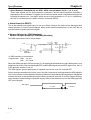
H Servo Driver Requiring External Regenerative Resistors
Servomotor models connecting to external regenerative resistors and complying with EC Directives are
available.
These Servomotor models are available to vertical shaft applications and other applications that generate high regenerative energy.
For detailed information of external regenerative resistors, refer to 3-6 Regenerative Energy Absorption.
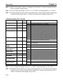
H Model Number Legend
D Servo Driver
R88D-UTjjj-j
1 2 3
Legend
number
Item
1
Maximum output current
2
Applicable standard
3
Special specifications
Symbol
(example)
24
40
H
V
No indication
RG
E
Description
Approx. 24 A
Approx. 40 A
Models not conforming to standards
Models conforming to EC Directives
--Models requiring external regenerative
resistors (see note 1)
Special specifications for Europe
Note Although the R88D-UT110V and R88D-UT160H-E have no indication for the regenerative resistor specifications, these models require external regenerative resistors.
1-2
1-2
Chapter 1
Introduction
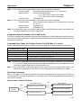
D Servomotors
R88M-Ujjjjjj-jjj
1
2 3 4 5 6
4, 5, and 6: Option Specifications
Legend
number
Item
1
Motor capacity
2
Rated revolution
3
Applicable
standard/encoder type
Symbol
(example)
1K0
1K3
15
30
H
V
X
4
Brake specifications
5
Oil seal specifications
6
Shaft shape
No indication
B
No indication
O
No indication
S1
Description
1.0 kW
1.3 kW
1,500 r/min
3,000 r/min
Models not conforming to standards
Incremental encoder
Models conforming to EC Directives
Incremental encoder
Models conforming to EC Directives
Absolute encoder
Without brake
With brake
Without oil seal
With oil seal
Straight shaft without key
Straight shaft with key (see note 2)
Note 1. Servomotors with absolute encoders and those with oil seals are available as models conforming to EC Directives.
Note 2. Models conforming to EC Directives and models for 1,500 r/min are available only for straight
shafts with keys.
Note 3. For details about model numbers, refer to 6-3 OMNUC U-series Models. For details about
combination of Servo Drivers and Servomotors, refer to 6-4 Combinations of Servo Drivers
and Servomotors.
1-3
Chapter 1
Introduction
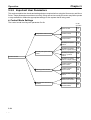
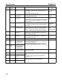
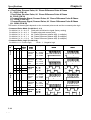
H Control Functions
Any one of the following 12 control modes can be selected in the parameter settings, thereby allowing
various applications with a single Servo Driver.
Control mode
Speed control (Analog command)
Position control (Pulse train command)
Torque control (Analog command)
Internal speed control settings
Internal speed control settings
Internal speed control settings
Internal speed control settings
Position control (Pulse train command)
Position control (Pulse train command)
Speed control (Analog command)
Speed control (Analog command)
Position control (Pulse train command)
[Factory setting]
¨
¨
¨
¨
¨
¨
¨
¨
Speed control (Analog command)
Position control (Pulse train command)
Torque control (Analog command)
Speed control (Analog command)
Torque control (Analog command)
Torque control (Analog command)
Position-lock stop
Pulse prohibit
H Auto-tuning
The gain can be adjusted automatically when the responsiveness has been selected to match the rigidity of the mechanical system. The auto-tuning feature automatically finds the optimum adjustment to
match the load, with no need for difficult operations.
H Monitor
Displays the driver’s operating status on the Parameter Unit.
The following items can be monitored: speed feedback, speed commands, torque commands,
number of pulses from the U-phase edge, electrical angle, the internal status (bit display), command pulse speed, position deviation, and input pulse counter.
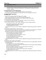
H Jog Operation
Forward/Reverse motor operation can be controlled from the Parameter Unit. Rotational speed can
be set in the parameters.
H Automatic Adjustment of Control Offset (Speed Control and Torque
Control)
The offsets of the speed command input and torque command input can be adjusted automatically.
H Electronic Gear Function (Position Control)
This function turns the motor by the number of pulses obtained by applying the gear ratio to the number of command pulses. It can be effectively used in the following situations.
S When fine tuning positions and speeds while synchronizing two lines.
S When using a controller with a short command pulse frequency.
S When setting the mechanical movement per pulse to amounts such as 0.01 mm.
The electronic gear ratio is set by parameters (numerator: G1; denominator: G2). The setting range
for G1 and G2 is 1 to 65,535, with 0.01
(G1/G2)
100.
1-4
1-4
Chapter 1
Introduction
H Encoder Resolution Function
This function allows the encoder signal output from the driver to be set anywhere within the ranges
shown below for incremental.
S 1,500-r/min models:
16 to 8,192 pulses/revolution
S 3,000-r/min [Incremental] models:
16 to 4,096 pulses/revolution
S 3,000-r/min [Absolute] models:
16 to 8,192 pulses/revolution
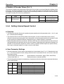
H Soft Start Function (Speed Control, Internal Speed Control Settings)
This function causes the motor to be started/stopped in the preset acceleration/deceleration times,
allowing a simple position control system to be constructed without a Positioner or Host Controller.
The acceleration and deceleration times are set separately, and the setting range is 0 to 10 s for
each.
H Pulse Smoothing Function (Position Control)
Applying acceleration and deceleration to command pulses enables tracking of high-frequency
commands. The setting is the same for acceleration and deceleration times, and the range is 0 to
64 ms.
H Reverse Mode
Forward/Reverse commands can be switched in the parameters, without changing the wiring to the
motor or encoder.
H Brake Interlock Output
Outputs a timing signal interlocked with the motor’s ON/OFF status and rotational speed. The holding brake of a motor with a brake can be operated reliably.
H Output Signal Selection Function
Any three output signals can be selected for output from among the following seven: Positioning
completed, motor rotation detection, servo preparation completed, electrical current limit detection,
brake interlock, overload warning, and overload alarm.
H Overtravel Sequence
An overtravel sequence compatible with the system can be selected. There are three deceleration
methods available: dynamic brake deceleration, free-run deceleration, and emergency-stop torque
deceleration (parameter setting).
H Feed-forward Function, Bias Function (Position Control)
These functions reduce the position control time.
S Feed-forward Function
Reduces the position control time by reducing the number of pulses accumulated in the error
counter.
S Bias Function
Reduces the position control time by adding the bias revolutions to the speed control when the
error counter value exceeds the position completion range.
1-5
Introduction
Chapter 1
H Personal Computer Monitor
The special Servo Driver Communications Software allows parameter setting, speed and current
monitoring, I/O monitoring, auto-tuning, and jog operations to be performed from a personal computer. It is also possible to perform multiple-axis communications that set the parameters and monitor operation of several drivers.
1-6
1-6
Chapter 1
Introduction
1-2
System Configuration
Controller (Voltage Output Models)
+
SYSMAC C/CV
Programmable
Controller
Motion Control Unit
CV500-MC221/421
C200H-MC221
Position Control
Unit
C500-NC222-E
Parameter Units
Controller (Pulse Train Output Models)
OMNUC U-series AC Servo Driver
+
SYSMAC C/CV
Programmable
Controller
Position Control Units
C500-NC111-EV1
C500-NC211
C200H-NC112
C200H-NC211
C200H-NC113
C200H-NC213
C200H-NC413
[Incremental]
[Absolute]
OMNUC U-series AC Servomotor
Note Motors with absolute encoders can be used in combination with CV500-MC221/421 or C200HMC221 Motion Control Units.
1-7
Chapter 1
Introduction
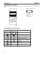
1-3
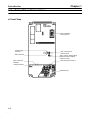
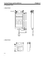
Servo Driver Nomenclature
H Front View
R88D-UT40H
CN3: Parameter
Unit connector
Power supply
indicator
Alarm indicator
CN1: Control I/O
connector
CN4: Connector for
monitor output
SW1: Unit No. setting switch
(when personal computer
monitor is used)
CN2: Encoder connector
Charge indicator
Terminal block
1-8
1-8
Chapter 1
Introduction
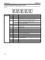
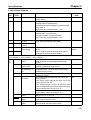
1-4
Applicable Standards and Models
H Applicable Standards
EC
Directives
Low voltage
EMC
Product
AC Servo Driver
Applicable standard
EN61010-1
AC Servo Motor
IEC34-1, -5, -8, -9
AC Servo Driver
EN55011 class A
and AC Servomotor group 1
EN50082-2
Remarks
Safety requirements for electrical
equipment for measurement, control, and
laboratory use.
Rotating electrical machines.
Limits and methods of measurement of
radio disturbance characteristics of
industrial, scientific, and medical (ISM)
radio-frequency equipment.
Electromagnetic compatibility generic
immunity standard, Part 2 Industrial
environment.
Note Installation under the conditions specified in 2-3-3 Wiring Conditions Satisfying EMC Directives is
required to conform to EMC Directives.
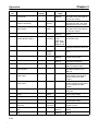
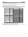
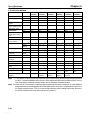
H Applicable Models
Supply voltage
200 VAC
Output
1 kW
1.3 kW
1.5 kW
1.8 kW
2 kW
2.9 kW
3 kW
4 kW
4.4 kW
5.0 kW
5.5 kW
AC Servo Driver
AC Servomotor
Incremental
Encoder
Absolute Encoder
R88D-UT24V
R88D-UT24V-RG
R88D-UT40V
R88D-UT40V-RG
R88M-U1K030V-jS1
R88M-U1K030X-jS1
R88M-U1K315V-jS1
R88M-U1K315X-jS1
R88M-U1K530V-jS1
R88M-U1K530X-jS1
R88D-UT60V
R88D-UT60V-RG
R88M-U1K815V-jS1
R88M-U1K815X-jS1
R88M-U2K030V-jS1
R88M-U2K030X-jS1
R88D-UT80V
R88D-UT80V-RG
R88M-U2K915V-jS1
R88M-U2K915X-jS1
R88M-U3K030V-jS1
R88M-U3K030X-jS1
R88D-UT110V
R88M-U4K030V-jS1
R88M-U4K030X-jS1
R88M-U4K415V-jS1
R88M-U4K415X-jS1
R88M-U5K030V-jS1
R88M-U5K030X-jS1
R88M-U5K515V-jS1
R88M-U5K515X-jS1
R88D-UT160V-E
1-9
2
Chapter 2
System Design and Installation
2-1
2-2
2-3
Installation
Wiring and Connections
(Models Not Conforming to Standards)
Wiring and Connections
(Models Conforming to EC Directives)
System Design and Installation
Chapter 2
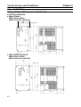
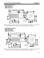
2-1 Installation
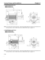
2-1-1 External Dimensions (Unit: mm)
H AC Servo Drivers
D R88D-UT40H-E
R88D-UT24V/-UT40V
R88D-UT24V-RG/-UT40V-RG
110
92
60.5
250
235
189.5
Two, 5.5 dia.
5.5
35
125
65
D R88D-UT60H-E/-UT80H-E
R88D-UT60V/-UT80V
R88D-UT60V-RG/-UT80V-RG
135
117
60.5
250
235
189.5
Two, 5.5 dia.
5.5
2-2
2-2
35
125
65
System Design and Installation
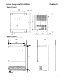
Chapter 2
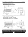
D R88D-UT110H-E
210
194
22
250
Two, 6 dia.
235
150
6
35
121
69
D R88D-UT160H-E
R88D-UT110V/-UT160V-E
230
240
Two, 7 dia.
7
350
180
335
25
7.5
2-3
System Design and Installation
Chapter 2
H Parameter Units
D R88A-PR02U
Two, 4.5-mm
dia. holes
18.5
63
50
7
125 135
(8)
1000
D R88A-PR03U
54
57.5
2-4
2-4
15
6.9
System Design and Installation
Chapter 2
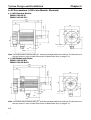
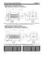
H AC Servomotor (1,500-r/min Models: Incremental)
D 1.3-kW Standard Models:
R88M-U1K315H-S1
R88M-U1K315V-S1
R88M-U1K315V-OS1
243
185
58
46
130
165 dia.
145 dia.
109
88
130
110h7 dia.
22h6 dia.
12
12
Four, 9 dia.
6
112
164
Note The model number with the suffix “S1” indicates a straight-shaft motor with key. For dimensions of
the key sections, refer to Shaft Dimensions of Motors with Keys on page 2-15.
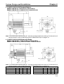
D 1.3-kW Models with Brake:
R88M-U1K315H-BS1
R88M-U1K315V-BS1
R88M-U1K315V-BOS1
281
58
12
145 dia.
130
165 dia.
120
88
22h6 dia.
130
110h7 dia.
223
47
12
6
Four, 9 dia.
103
202
Note The model number with the suffix “S1” indicates a straight-shaft motor with key. For dimensions of
the key sections, refer to Shaft Dimensions of Motors with Keys on page 2-15.
2-5
System Design and Installation
Chapter 2
D 1.8-kW/2.9-kW/4.4-kW Standard Models:
R88M-U1K815H-S1/-U2K915H-S1/-U4K415H-S1
R88M-U1K815V-S1/-U2K915V-S1/-U4K415V-S1
R88M-U1K815V-OS1/-U2K915V-OS1/-U4K415V-OS1
L
LL
35h6 dia.
79
47
180
200 dia.
180
140
88
114.3h 7 dia.
230 dia.
18
Four, 13.5 dia.
3.2
KA
KB
Note The model number with the suffix “S1” indicates a straight-shaft motor with key. For dimensions of
the key sections, refer to Shaft Dimensions of Motors with Keys on page 2-15.
D 1.8-kW/2.9-kW/4.4-kW Models with Brake:
R88M-U1K815H-BS1/-U2K915H-BS1/-U4K415H-BS1
R88M-U1K815V-BS1/-U2K915V-BS1/-U4K415V-BS1
R88M-U1K815V-BOS1/-U2K915V-BOS1/-U4K415V-BOS1
200 dia.
230 dia.
146
88
114.3h7 dia.
180
180
79
47
35h6 dia.
L
LL
18
KB
3.2
Four, 13.5 dia.
KA
Note The model number with the suffix “S1” indicates a straight-shaft motor with key. For dimensions of
the key sections, refer to Shaft Dimensions of Motors with Keys on page 2-15.
Standard Models
Models with Brake
Model
L
LL
KA
KB
Model
L
LL
KA
KB
R88M-U1K815j-jS1
245
166
89
145
R88M-U1K815j-BjS1
296
217
79
196
R88M-U2K915j-jS1
271
192
115
171
R88M-U2K915j-BjS1
322
243
105
222
R88M-U4K415j-jS1
305
226
149
205
R88M-U4K415j-BjS1
356
277
139
256
2-6
2-6
System Design and Installation
Chapter 2
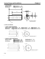
D 5.5-kW Standard Models:
R88M-U5K515H-S1
R88M-U5K515V-S1
R88M-U5K515V-OS1
373
113
47
18
42h6 dia.
260
3.2
180
200 dia.
180
Four, 13.5 dia.
102
10
150
125
88
114.3h7 dia.
230 dia.
174
47
239
47
Note The model number with the suffix “S1” indicates a straight-shaft motor with key. For dimensions of
the key sections, refer to Shaft Dimensions of Motors with Keys on page 2-15.
D 5.5-kW Models with Brake:
R88M-U5K515H-BS1
R88M-U5K515V-BS1
R88M-U5K515V-BOS1
424
113
311
180
18
3.2
42h6 dia.
47
200 dia.
180
10
102
150
125
88
123
114.3h7 dia.
230 dia.
Four, 13.5 dia.
174
231
47
47
290
Note The model number with the suffix “S1” indicates a straight-shaft motor with key. For dimensions of
the key sections, refer to Shaft Dimensions of Motors with Keys on page 2-15.
2-7
System Design and Installation
Chapter 2
H AC Servomotors (1,500 r/min Models: Absolute)
D 1.3-kW Standard Models:
R88M-U1K315X-S1
R88M-U1K315X-OS1
257
199
58
60
22h6 dia.
130
145 dia.
109
88
130
110h7dia.
165 dia.
12
12
Four, 9 dia.
6
112
178
Note The model number with the suffix “S1” indicates a straight-shaft motor with key. For dimensions of
the key sections, refer to Shaft Dimensions of Motors with Keys on page 2-15.
D 1.3-kW Models with Brake:
R88M-U1K315X-BS1
R88M-U1K315X-BOS1
295
58
237
22h6 dia.
60
145 dia.
130
165 dia.
12
12
6
120
88
110h7 dia.
130
Four, 9 dia.
103
216
Note The model number with the suffix “S1” indicates a straight-shaft motor with key. For dimensions of
the key sections, refer to Shaft Dimensions of Motors with Keys on page 2-15.
2-8
2-8
System Design and Installation
Chapter 2
D 1.8-kW/2.9-kW/4.4-kW Standard Models:
R88M-U1K815X-S1/-U2K915X-S1/-U4K415X-S1
R88M-U1K815X-OS1/-U2K915X-OS1/-U4K415X-OS1
L
LL
79
61
35h6 dia.
180
180
230 dia.
140
88
114h7 dia.
200 dia.
18
Four, 13.5 dia.
3.2
KA
KB
Note The model number with the suffix “S1” indicates a straight-shaft motor with key. For dimensions of
the key sections, refer to Shaft Dimensions of Motors with Keys on page 2-15.
D 1.8-kW/2.9-kW/4.4-kW Models with Brake:
R88M-U1K815X-BS1/-U2K915X-BS1/-U4K415X-BS1
R88M-U1K815X-BOS1/-U2K915X-BOS1/-U4K415X-BOS1
L
LL
79
35h6 dia.
62
180
200 dia.
180
146
88
114h7 dia.
230 dia.
Four, 13.5 dia.
18
KA
3.2
KB
Note The model number with the suffix “S1” indicates a straight-shaft motor with key. For dimensions of
the key sections, refer to Shaft Dimensions of Motors with Keys on page 2-15.
Standard Models
Models with Brake
Model
L
LL
KA
KB
Model
L
LL
KA
KB
R88M-U1K815X-jS1
259
180
89
159
R88M-U1K815X-BjS1
310
231
79
209
R88M-U2K915X-jS1
285
206
115
184
R88M-U2K915X-BjS1
336
257
105
235
R88M-U4K415X-jS1
319
240
149
218
R88M-U4K415X-BjS1
370
291
139
269
2-9
System Design and Installation
Chapter 2
D 5.5-kW Standard Models:
R88M-U5K515X-S1
R88M-U5K515X-OS1
387
274
113
18
42h6 dia.
61
3.2
180
200 dia.
150
125
88
180
114h7 dia.
230 dia.
Four, 13.5 dia.
10
102
174
47
47
252
Note The model number with the suffix “S1” indicates a straight-shaft motor with key. For dimensions of
the key sections, refer to Shaft Dimensions of Motors with Keys on page 2-15.
D 5.5-kW Models with Brake:
R88M-U5K515X-BS1
R88M-U5K515X-BOS1
438
325
113
62
42h6 dia.
3.2
230 dia.
125
200 dia.
10
102
174
231
150
180
180
114h7 dia.
88
123
1.8
Four, 13.5 dia.
47
47
303
Note The model number with the suffix “S1” indicates a straight-shaft motor with key. For dimensions of
the key sections, refer to Shaft Dimensions of Motors with Keys on page 2-15.
2-10
2-10
System Design and Installation
Chapter 2
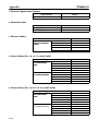
H AC Servomotors (3,000-r/min Models: Incremental)
D 1.0-kW/1.5-kW/2.0-kW Standard Models:
R88M-U1K030H/-U1K530H/-U2K030H
R88M-U1K030V-S1/-U1K530V-S1/-U2K030V-S1
R88M-U1K030V-OS1/-U1K530V-OS1/-U2K030V-OS1
L
LL
45
46
130 dia.
100
95h7 dia.
24h6 dia.
100
115 dia.
96
87
40
10
Four, 7 dia.
3
Note The model number with the suffix “S1” indicates a straight-shaft motor with key. For dimensions of
the key sections, refer to Shaft Dimensions of Motors with Keys on page 2-15.
D 1.0-kW/1.5-kW/2.0-kW Models with Brake:
R88M-U1K030H-B/-U1K530H-B/-U2K030H-B
R88M-U1K030V-BS1/-U1K530V-BS1/-U2K030V-BS1
R88M-U1K030V-BOS1/-U1K530V-BOS1/-U2K030V-BOS1
L
LL
45
46
100
95h7 dia.
24h6 dia.
100
130 dia.
115 dia.
10
3
100
87
40
Four, 7 dia.
Note The model number with the suffix “S1” indicates a straight-shaft motor with key. For dimensions of
the key sections, refer to Shaft Dimensions of Motors with Keys on page 2-15.
Standard Models
Models with Brake
Model
L
LL
Model
L
LL
R88M-U1K030j-jS1
194
149
R88M-U1K030j-BjS1
238
193
R88M-U1K530j-jS1
220
175
R88M-U1K530j-BjS1
264
219
R88M-U2K030j-jS1
243
198
R88M-U2K030j-BjS1
287
242
2-11
System Design and Installation
Chapter 2
D 3.0-kW/4.0-kW/5.0-kW Standard Models:
R88M-U3K030H/-U4K030H/-U5K030H
R88M-U3K030V-S1/-U4K030V-S1/-U5K030V-S1
88M-U3K030V-OS1/-U4K030V-OS1/-U5K030V-OS1
L
LL
63
130
110h7 dia.
130
28h6 dia.
46
165 dia.
145 dia.
114
87
55
12
Four, 9 dia.
6
Note The model number with the suffix “S1” indicates a straight-shaft motor with key. For dimensions of
the key sections, refer to Shaft Dimensions of Motors with Keys on page 2-15.
D 3.0-kW/4.0-kW/5.0-kW Models with Brake:
R88M-U3K030H-B/-U4K030H-B/-U5K030H-B
R88M-U3K030V-BS1/-U4K030V-BS1/-U5K030V-BS1
R88M-U3K030V-BOS1/-U4K030V-BOS1/-U5K030V-BOS1
L
LL
63
46
110h7 dia.
130
28h6 dia.
130
165 dia.
145 dia.
119
87
55
12
6
Four, 9 dia.
Note The model number with the suffix “S1” indicates a straight-shaft motor with key. For dimensions of
the key sections, refer to Shaft Dimensions of Motors with Keys on page 2-15.
Standard Models
Models with Brake
Model
L
LL
Model
L
LL
R88M-U3K030j-jS1
262
199
R88M-U3K030j-BjS1
300
237
R88M-U4K030j-jS1
299
236
R88M-U4K030j-BjS1
337
274
R88M-U5K030j-jS1
339
276
R88M-U5K030j-BjS1
377
314
2-12
2-12
System Design and Installation
Chapter 2
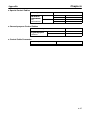
H AC Servomotors (3,000-r/min Models: Absolute)
D 1.0-kW/1.5-kW/2.0-kW Standard Models:
R88M-U1K030X-S1/-U1K530X-S1/-U2K030X-S1
R88M-U1K030X-OS1/-U1K530X-OS1/-U2K030X-OS1
L
LL
45
60
100
95h7 dia.
24h6 dia.
100
130 dia.
115 dia.
96
87
40
10
Four, 7 dia.
3
Note The model number with the suffix “S1” indicates a straight-shaft motor with key. For dimensions of
the key sections, refer to Shaft Dimensions of Motors with Keys on page 2-15.
D 1.0-kW/1.5-kW/2.0-kW Models with Brake:
R88M-U1K030X-BS1/-U1K530X-BS1/-U2K030X-BS1
R88M-U1K030X-BOS1/-U1K530X-BOS1/-U2K030X-BOS1
L
LL
45
60
100
95h7 dia.
24h6 dia.
100
130 dia.
115 dia.
100
87
40
10
3
Four, 7 dia.
Note The model number with the suffix “S1” indicates a straight-shaft motor with key. For dimensions of
the key sections, refer to Shaft Dimensions of Motors with Keys on page 2-15.
Standard Models
Model
L
R88M-U1K030j-jS1
208
R88M-U1K530j-jS1
234
R88M-U2K030j-jS1
257
LL
163
189
212
Models with Brake
Model
L
R88M-U1K030j-BjS1
252
R88M-U1K530j-BjS1
278
R88M-U2K030j-BjS1
301
LL
207
233
256
2-13
System Design and Installation
Chapter 2
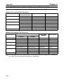
D 3.0-kW/4.0-kW/5.0-kW Standard Models:
R88M-U3K030X-S1/-U4K030X-S1/-U5K030X-S1
R88M-U3K030X-OS1/-U4K030X-OS1/-U5K030X-OS1
L
LL
63
130
110h7 dia.
130
28h6 dia.
60
165 dia.
145 dia.
114
87
55
12
Four, 9 dia.
6
Note The model number with the suffix “S1” indicates a straight-shaft motor with key. For dimensions of
the key sections, refer to Shaft Dimensions of Motors with Keys on page 2-15.
D 3.0-kW/4.0-kW/5.0-kW Models with Brake:
R88M-U3K030X-BS1/-U4K030X-BS1/-U5K030X-BS1
R88M-U3K030X-BOS1/-U4K030X-BOS1/-U5K030X-BOS1
L
LL
63
130
110h7 dia.
130
28h6 dia.
60
165 dia.
145 dia.
119
87
55
12
6
Four, 9 dia.
Note The model number with the suffix “S1” indicates a straight-shaft motor with key. For dimensions of
the key sections, refer to Shaft Dimensions of Motors with Keys on page 2-15.
Standard Models
Model
L
R88M-U3K030j-jS1
276
R88M-U4K030j-jS1
313
R88M-U5K030j-jS1
353
2-14
2-14
LL
213
250
290
Models with Brake
Model
L
R88M-U3K030j-BjS1
314
R88M-U4K030j-BjS1
351
R88M-U5K030j-BjS1
391
LL
251
288
328
System Design and Installation
Chapter 2
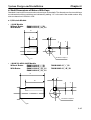
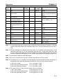
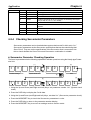
H Shaft Dimensions of Motors With Keys
Standard U-series AC Servomotors do not have keys on the shafts. The dimensions of motors with keys
are shown below. Motors with keys are indicated by adding “-S1” to the end of the model number. Key
slots are based on JIS B1301-1976.
D 1,500-r/min Models
· 1.3-kW Models
Without Brake:
With Brake:
R88M-U1K315j-jS1
R88M-U1K315j-BjS1
40
6
6
3.5
25
M5 effective depth 12
R1
· 1.8-kW/2.9-kW/4.4-kW Models
Without Brake:
R88M-U1K815j-jS1
R88M-U4K415j-jS1
With Brake:
R88M-U1K815j-BjS1
R88M-U4K415j-BjS1
R88M-U2K915j-jS1
R88M-U2K915j-BjS1
76
10
8
5
60
M12 effective depth 25
R1
2-15
System Design and Installation
· 5.5-kW Models
Without Brake:
With Brake:
Chapter 2
R88M-U5K515j-jS1
R88M-U5K515j-BjS1
110
12
8
5
90
M16 effective depth 32
R1
D 3,000-r/min Models
· 1.0-kW/1.5-kW/2.0-kW Models
Without Brake: R88M-U1K030j-jS1 R88M-U1K530j-jS1 R88M-U2K030j-jS1
With Brake:
R88M-U1K030j-BjS1 R88M-U1K530j-BjS1 R88M-U2K030j-BjS1
32
4
24h6 dia
8
M8 effective depth 16
7
· 3.0-kW/4.0-kW/5.0-kW Models
Without Brake:
R88M-U3K030j-jS1
R88M-U5K030j-jS1
With Brake:
R88M-U3K030j-BjS1
R88M-U5K030j-BjS1
R88M-U4K030j-jS1
R88M-U4K030j-BjS1
50
4
28h6 dia
8
7
2-16
2-16
M8 effective depth 16
System Design and Installation
Chapter 2
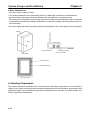
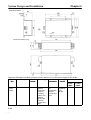
2-1-2 Installation Conditions
H AC Servo Drivers
D Space Around Drivers
· Install Servo Drivers according to the dimensions shown in the following illustration to ensure proper
heat dispersion and convection inside the panel. Also install a fan for circulation if Servo Drivers are
installed side by side to prevent uneven temperatures from developing inside the panel.
· Mount the Servo Drivers vertically (so that the model number and writing can be read).
W
30 mm min.
50 mm min.
Servo Driver
Fan
Servo Driver
Servo Driver
Fan
W
W = 10 mm min.
Side of Unit
50 mm min.
D Operating Environment
Be sure that the environment in which Servo Drivers are operated meets the following conditions.
· Ambient operating temperature:
0°C to +55°C
· Ambient operating humidity:
20% to 85% (RH, with no condensation)
· Atmosphere:
No corrosive gases.
D Ambient Temperature
· Servo Drivers should be operated in environments in which there is minimal temperature rise to
maintain a high level of reliability.
· Temperature rise in any Unit installed in a closed space, such as a control box, will cause the ambient
temperature to rise inside the entire closed space. Use a fan or a air conditioner to prevent the ambient temperature of the Servo Driver from exceeding 55°C.
· Unit surface temperatures may rise to as much as 30°C above the ambient temperature. Use heatresistant materials for wiring, and keep separate any devices or wiring that are sensitive to heat.
· The service life of a Servo Driver is largely determined by the temperature around the internal electrolytic capacitors. The service life of an electrolytic capacitor is affected by a drop in electrolytic volume and an increase in internal resistance, which can result in overvoltage alarms, malfunctioning
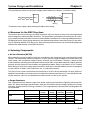
due to noise, and damage to individual elements. If a Servo Driver is always operated at the maximum ambient temperature of 40°C and at 80% of the rated torque, then a service life of approximately 50,000 hours can be expected. A drop of 10°C in the ambient temperature will double the
expected service life.
2-17
System Design and Installation
Chapter 2
D Keeping Foreign Objects Out of Units
· Place a cover over the Units or take other preventative measures to prevent foreign objects, such as
drill filings, from getting into the Units during installation. Be sure to remove the cover after installation is complete. If the cover is left on during operation, heat buildup may damage the Units.
· Take measures during installation and operation to prevent foreign objects such as metal particles,
oil, machining oil, dust, or water from getting inside of Servo Drivers.
H AC Servomotors
D Operating Environment
Be sure that the environment in which the Servomotor is operated meets the following conditions.
· Ambient operating temperature:
0°C to +40°C
· Ambient operating humidity:
20% to 80% (RH, with no condensation)
· Atmosphere:
No corrosive gases.
D Impact and Load
· The Servomotor is resistant to impacts of up to
98 m/s2 {10 G}. Do not subject it to heavy impacts or
loads during transport, installation, or positioning. In
addition, do not hold onto the encoder, cable, or connector areas when transporting it.
· Always use a pulley remover to remove pulleys,
couplings, or other objects from the shaft.
· Secure cables so that there is no impact or load placed on the cable connector areas.
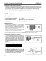
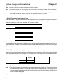
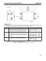
D Connecting to Mechanical Systems
· The axial loads for Servomotors are specified in section 5-2-4. If an axial load greater than that specified
is applied to a Servomotor, it will reduce the service
life of the motor bearings and may damage the motor
shaft. When connecting to a load, use couplings that
can sufficiently absorb mechanical eccentricity and
variation.
Motor shaft center line
Ball screw center line
Shaft core
displacement
Recommended Coupling
Name
Oldham coupling
Maker
Myghty Co., Ltd
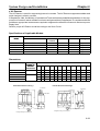
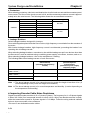
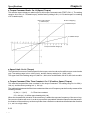
· For spur gears, an extremely large radial load may
be applied depending on the gear precision. Use
spur gears with a high degree of accuracy (for exam- Tooth precision
ple, JIS class 2: normal line pitch error of 6 mm max.
for a pitch circle diameter of 50 mm). If the gear preciBacklash
sion is not adequate, allow backlash to ensure that
no radial load is placed on the motor shaft.
2-18
2-18
Adjust backlash
by adjusting the
distance between
shafts.
System Design and Installation
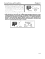
Chapter 2
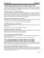
· Bevel gears will cause a load to be applied in the
thrust direction depending on the structural precision, the gear precision, and temperature changes.
Provide appropriate backlash or take other measures to ensure that no thrust load is applied which
exceeds specifications.
Bevel gear
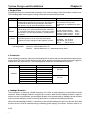
· Do not put rubber packing on the flange surface. If
the flange is mounted with rubber packing, the motor
flange may separate due to the tightening strength.
Make moveable.
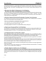
· When connecting to a V-belt or timing belt, consult the maker for belt selection and tension. A radial
load twice the belt tension will be placed on the motor shaft. Do not allow a radial load exceeding
specifications to be placed on the motor shaft due to belt tension. If an excessive radial load is
applied, the motor shaft may be damaged. Set up the structure so that the radial load can be
adjusted. A large radial load may also be applied as a result of belt vibration. Attach a brace and
adjust Servo Driver gain so that belt vibration is minimized.
Pulley
Belt
Tension
Pulley for tension adjustment
(Make adjustable.)
Motor shaft
Pulley
2-19
System Design and Installation
Chapter 2
D Water and Drip Resistance
· The Servomotor is not of waterproof construction.
The Servomotor is provided with either of the following protection.
Models not complying with EC Directives: IP65 (excluding the shaft penetration areas)
Models complying with EC Directives: IP55 (including the shaft penetration areas)
The standard cable conforms to IP30. If the Power Cable or Encoder Cable is used in places wet
with sprayed water, connect waterproof connectors to the Cable.
If the equipment incorporating the Servomotor must comply with EC Directives, connect the following connectors to the Power Cable and Encoder Cable.
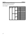
Recommended Connectors for Power Cables
S 1,500-r/min Models
Motor model
Without R88M-U1K315j-jS1
brake
R88M-U1K815j-jS1
R88M-U2K915j-jS1
R88M-U4K415j-jS1
Connector model
Angled type
CE05-8A18-10SD-B-BAS
Straight type
CE05-6A18-10SD-B-BSS
Angled type
JL04V-8A22-22SE-EB
Straight type
JL04V-6A22-22SE-EB
Cable clamp model
Maker
For sheath external diam- DDK Ltd.
eter of 10.5 to 14.1 dia.:
CE3057-10A-1 (D265)
For sheath external diameter of 8.5 to 11 dia.:
CE3057-10A-2 (D265)
For sheath external diameter of 6.5 to 8.7 dia.:
CE3057-10A-3 (D265)
For sheath external diam- Japan Aviation
eter of 6.5 to 9.5 dia.:
Electronics
JL04-2022C K (09)
Industry, Ltd.
(JAE)
For sheath external diameter of 9.5 to 13 dia.:
JL04-2022CK (12)
R88M-U5K515j-jS1
2-20
2-20
Straight type
JL04V-6A32-17SE
For sheath external diameter of 12.9 to 16 dia.:
JL04-2022CK (14)
(Note)
Japan Aviation
Electronics
Industry, Ltd.
(JAE)
Cable clamp
Nippon Flex
Co., Ltd.
System Design and Installation
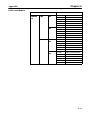
With
brake
Motor model
R88M-U1K315j-BjS1
Connector model
Angled type
JL04V-8A20-15SE-EB
Straight type
JL04V-6A20-15SE-EB
Chapter 2
Cable clamp model
Maker
For sheath external diam- Japan Aviation
eter of 6.5 to 9.5 dia. :
Electronics
JL04-2022C K (09)
Industry, Ltd.
(JAE)
For sheath external diam-
eter of 9.5 to 13 dia. :
JL04-2022C K (12)
For sheath external diameter of 12.5 to 15.9 dia. :
JL04-2022C K (14)
R88M-U1K815j-BjS1
R88M-U2K915j-BjS1
R88M-U4K415j-BjS1
Angled type
JL04V-8A24-10SE-EB
Straight type
JL04V-6A24-10SE-EB
For sheath external diam- Japan Aviation
eter of 9 to 12 dia. :
Electronics
JL04-2428C K (11)
Industry, Ltd.
(JAE)
For sheath external diam-
eter of 12 to 15 dia. :
JL04-2428C K (14)
For sheath external diameter of 15 to 18 dia. :
JL04-2428C K (17)
R88MFor
Straight type
U5K515j-BjS1 motiv JL04V-6A32-17SE
e
power
For
braking
Angled type
CE05-8A10SL-3SC-BBAS
Straight type
CE-05-6A10SL-3SCB-BSS
For sheath external diameter of 18 to 20 dia. :
JL04-2428C K (20)
(See note)
Japan Aviation
Electronics
Industry, Ltd.
(JAE)
Cable clamp
Nippon Flex
Co., Ltd.
For sheath external diam- DDK Ltd.
eter of 3.6 to 5.6 dia.:
CE3057-4A-1 (D265)
Note
Angle
ACA-16RL-MS32F
ACA-20RL-MS32F
ACA-24RL-MS32F
ACA-28RL-MS32F
ACA-32RL-MS32F
ACA-36RL-MS32F
Straight
ACS-16RL-MS32F
ACS-20RL-MS32F
ACS-24RL-MS32F
ACS-28RL-MS32F
ACS-32RL-MS32F
ACS-36RL-MS32F
Applicable cable diameter
12 to 16 dia.
16 to 20 dia.
20 to 24 dia.
24 to 28 dia.
28 to 32 dia.
32 to 36 dia.
2-21
System Design and Installation
Chapter 2
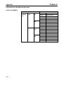
S 3,000-r/min Model
Motor model
Without R88M-U1K030j-j
brake
R88M-U1K530j-j
R88M-U2K030j-j
R88M-U3K030j-j
R88M-U4K030j-j
R88M-U5K030j-j
With
brake
R88M-U1K030j-Bj
R88M-U1K530j-Bj
R88M-U2K030j-Bj
R88M-U3K030j-Bj
R88M-U4K030j-Bj
R88M-U5K030j-Bj
Connector model
Angled type
CE05-8A18-10SD-B-BAS
Straight type
CE05-6A18-10SD-B-BSS
Angled type
JL04V-8A22-22SE-EB
Straight type
JL04V-6A22-22SE-EB
Angled type
JL04V-8A20-15SE-EB
Straight type
JL04V-6A20-15SE-EB
Angled type
JL04V-8A24-10SE-EB
Straight type
JL04V-6A24-10SE-EB
Cable clamp model
Maker
For sheath external diam- DDK Ltd.
eter of 6.5 to 8.7 dia.:
CE3057-10A-3 (D265)
For sheath external diameter of 8.5 to 11 dia.:
CE3057-10A-2 (D265)
For sheath external diameter of 10.5 to 14.1 dia.:
CE3057-10A-1 (D265)
For sheath external diam- Japan Aviation
eter of 6.5 to 9.5 dia.:
Electronics IndusJL04-2022CK(09)
try, Ltd. (JAE)
For sheath external diameter of 9.5 to 13 dia.:
JL04-2022CK(12)
For sheath external diameter of 12.9 to 15.9 dia.:
JL04-2022CK(14)
For sheath external diam- Japan Aviation
eter of 6.5 to 9.5 dia.:
Electronics IndusJL04-2022CK(09)
try, Ltd. (JAE)
For sheath external diameter of 9.5 to 13 dia.:
JL04-2022CK(12)
For sheath external diameter of 12.9 to 15.9 dia.:
JL04-2022C K(14)
For sheath external diam- Japan Aviation
eter of 9 to 12 dia.:
Electronics IndusJL04-2428CK(11)
try, Ltd. (JAE)
For sheath external diameter of 12 to 15 dia.:
JL04-2428CK(14)
For sheath external diameter of 15 to 18 dia.:
JL04-2428CK(17)
For sheath external diameter of 18 to 20 dia.:
JL04-2428CK(20)
2-22
2-22
System Design and Installation
Chapter 2
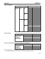
Recommended Connector for Encoder Cables
Motor model
All models
Connector model
Angled type
JA08A-20-295-J1-EB
Straight type
JA06A-20-295-J1-EB
Cable clamp model
For sheath external diameter of 6.5 to 9.5 dia.:
JL04-2022CKE(09)
+
For sheath external diameter of 9.5 to 13 dia.:
JL04-2022CKE(09)
For sheath external diameter of 12.9 to 16 dia.:
JL04-2022CKE(14)
Maker
Japan Aviation Electronics Industry, Ltd. (JAE)
· If the Servomotor is used in an environment in which condensation occurs, water may enter inside of
the encoder from the end surfaces of cables due to motor temperature changes. Either take measures to ensure that water cannot penetrate in this way, or use water-proof connectors. Even when
machinery is not in use, water penetration can be avoided by taking measures, such as keeping the
motor in servo-lock status, to minimize temperature changes.
· If machining oil with surfactants (e.g., coolant fluids) or their spray penetrate inside of the motor,
insulation defects or short-circuiting may occur. Take measures to prevent machining oil penetration.
D Oil Seal
If the motor shaft is exposed to oil or grease, use a Servomotor with an oil seal (with model number
suffix of “-jOj”). Servomotors with an oil seal conform to EC Directives.
D Other Precautions
· Do not apply commercial power directly to the Servomotor. The Servomotors run on synchronous
AC and use permanent magnets. Applying three-phase power will burn out the motor coils.
· Take measures to prevent the shaft from rusting. The shafts are coated with anti-rust oil when
shipped, but anti-rust oil or grease should also be applied when connecting the shaft to a load.
· Absolutely do not remove the encoder cover or take the motor apart. The magnet and the encoder
are aligned in the Servomotor. If they become misaligned, the motor will not operate.
2-23
System Design and Installation
2-2
Chapter 2
Wiring and Connections (Models Not Conforming to
Standards)
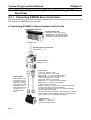
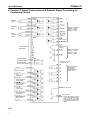
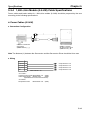
2-2-1 Connecting OMRON Servo Controllers
Use general-purpose control cable (purchased separately) to connect U-series AC Servomotors and
Servo Drivers to OMRON Servo Controllers.
H Connecting SYSMAC C-Series Position Control Units
Programmable Controller
SYSMAC C/CV
Position Control Unit
C500-NC222-E (Analog output)
3G2A5-NC111-EV1 (Pulse train output)
C500-NC211 (Pulse train output)
C200H-NC112 (Pulse train output)
C200H-NC211 (Pulse train output)
C200HW-NC113 (Pulse train output)
C200HW-NC213 (Pulse train output)
C200HW-NC413 (Pulse train output)
General-purpose Control Cable
R88A-CPUBjjjS
AC Servo Driver
R88D-UTjjH-E
Encoder Cable
R88A-CRUBjjjN
Power Cable
(1,500-r/min models: 1.3-kW
3,000-r/min models: 1.5- to 2.0-kW)
R88A-CAUBjjjS (for motor without brake)
R88A-CAUBjjjB (for motor with brake)
(1,500-r/min models: 1.8 to 4.4-kW
3,000-r/min models: 3.0- to 5.0-kW)
R88A-CAUCjjjS (for motor without brake)
R88A-CAUCjjjB (for motor with brake)
* 1,500-r/min models: 5.5-kW
Prepare a cable for 5.5-kW use for the 1,500-r/min
models if required. This cable is not sold by OMRON.
(For cable specifications, refer to 5-3-4 1,500-r/min
Models (5.5-kW) Cable Specifications.)
AC Servo Motor
R88M-Ujjj15H-jS1, R88M-Ujjj30H-j
(with incremental encoder)
2-24
2-24
System Design and Installation
Chapter 2
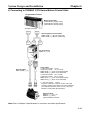
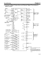
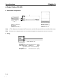
H Connecting to SYSMAC C/CV-Series Motion Control Units
Programmable Controller
Motion Control Unit
CV500-MC221 (Analog output)
CV500-MC421 (Analog output)
C200H-MC221 (Analog output)
SYSMAC CV/CVM1
General-purpose Control Cable
R88A-CPUBjjjM1 (for single axis)
R88A-CPUBjjjM2 (for double axis)
AC Servo Driver
R88D-UTjjH-E
Encoder Cable
R88A-CRUBjjjN
Power Cable
(1,500-r/min models: 1.3-kW
3,000-r/min models: 1.5- to 2.0-kW)
R88A-CAUBjjjS (for motor without brake)
R88A-CAUBjjjB (for motor with brake)
(1,500-r/min models: 1.8 to 4.4-kW
3,000-r/min models: 3.0- to 5.0-kW)
R88A-CAUCjjjS (for motor without brake)
R88A-CAUCjjjB (for motor with brake)
* 1,500-r/min models: 5.5-kW
Prepare a cable for 5.5-kW use for the 1,500-r/min
models if required. This cable is not sold by OMRON.
(For cable specifications, refer to 5-3-4 1,500-r/min
Models (5.5-kW) Cable Specifications.)
AC Servo Motor
R88M-Ujjj15H-jS1
R88M-Ujjj30H-j
(with incremental encoder)
Note Refer to Chapter 5 Specifications for connector and cable specifications.
2-25
System Design and Installation
Chapter 2
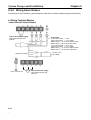
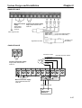
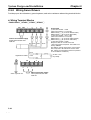
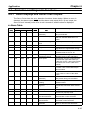
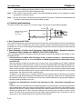
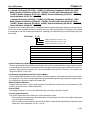
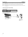
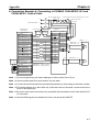
2-2-2 Wiring Servo Drivers
Provide proper wire diameters, ground systems, and noise resistance when wiring terminal blocks.
H Wiring Terminal Blocks
· R88D-UT40H-E/UT60H-E/UT80H-E
Control Circuit Power Supply
Single-phase 200/230 VAC
50/60 Hz
Red White
Black
Green
(1,500-r/min models: 1.8 to 4.4-kW
3,000-r/min models: 3.0- to 5.0-kW)
R88A-CAUCjjjS (for motor without brake)
R88A-CAUCjjjB (for motor with brake)
Brown
Signal line for brake
R
Class-3 ground min.
2-26
2-26
S
24 VDC ±10%
No polarity
Yellow
T
Power Cable
(1,500-r/min models: 1.3-kW
3,000-r/min models: 1.5- to 2.0-kW)
R88A-CAUBjjjS (for motor without brake)
R88A-CAUBjjjB (for motor with brake)
P
B
Main Circuit Power Supply
Three-phase 200/230 VAC
50/60 Hz
System Design and Installation
Chapter 2
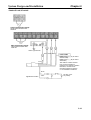
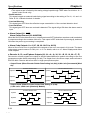
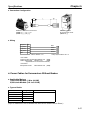
· R88D-UT110H-E
Main Circuit Power Control Circuit Power Supply
Single-phase 200/230 VAC
Supply
50/60 Hz
Three-phase
200/230 VAC
Red
50/60 Hz
Class-3 ground min.
White Black Green
Power Cable
R88A-CAUCjjjS (for motor without brake)
R88A-CAUCjjjB (for motor with brake)
Brown
24 VDC ±10%
No polarity
Yellow
Signal line for brake
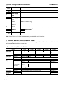
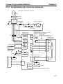
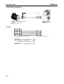
· R88D-UT160H-E
r
t
Connector Pin No.
C (Phase W)
* Prepare the power cables.
B (Phase V)
M
Control Circuit Power Supply
Single-phase 200/230 VAC
50/60 Hz
R
S
A (Phase U)
D (GR)
T
P
N
P1
B
U
V
W
Main Circuit Power Supply
Three-phase 200/230 VAC
50/60 Hz
Class-3 ground min.
R
R
Regenerative
Resistance
2-27
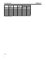
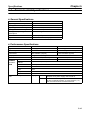
System Design and Installation
Name
Terminal
label
Frame ground
Main circuit
power supply
input
R
S
T
r
Control circuit
power supply
input
Regenerative
resistor
connection
terminals
t
P1
B
P
N
U
V
W
Main circuit DC
output
Motor connection
terminals
Frame ground
Chapter 2
Function
This is the ground terminal. Ground to a class-3 ground (to 100 W or less) or
better.
Three-phase 200/230 VAC (170 to 253 V), 50/60 Hz
Single-phase 200/230 VAC (170 to 253 V), 50/60 Hz
Regenerative resistor connection terminal for a Servo Driver of 5.5 kW min.
(R88D-UT160H-E only)
Do not connect anything to these terminals.
These are the output terminals to the Servomotor. Be careful to wire
Red
White them correctly.
Black
Green
Note Servo Drivers of 5.0 kW or less are not provided with the P1 terminal.
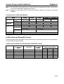
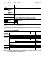
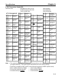
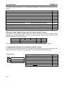
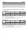
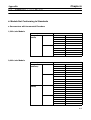
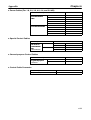
H Terminal Block Current and Wire Sizes
The following table shows the rated effective currents flowing to the Servo Driver, the sizes of the electrical wires, and terminal block screw size.
D Connection to 1,500-r/min Models
Servo Driver
(Watts)
Main circuit
power supply
input (R, S, T)
Effective current
R88D-UT40H-E
(1.3 kW)
8.0 A
Wire size
3.5
mm2
R88D-UT60H-E
(1.8 kW)
11.7 A
or AWG 12 min.
R88D-UT80H-E
(2.9 kW)
17.8 A
5.5
mm2
Screw diameter
M4
Control circuit
power supply
input (r, t)
Effective current
0.25 A
Wire size
1.25 mm2 or AWG 16 min.
Motor connection
terminal (U, V,
W)
Effective current
10.7 A
16.7 A
Wire size
3.5 mm2 or
AWG 12
5.5 mm2 or AWG 10 min.
Frame ground
Regenerative
resistor connection terminals
(P1, B)
2-28
2-28
R88D-UT110H-E
(4.4 kW)
R88D-UT160H-E
(5.5 kW)
26.4 A
33.9 A
or AWG 10 min.
8 mm2 or AWG 8
min.
M6
0.25 A
0.25 A
Screw diameter
0.25 A
0.25 A
32.8 A
42.1 A
M4
23.8 A
14.0 mm2 or
AWG 6 min.
Use OMRON standard cables.
(See note 2)
Motor connector’s applicable
cable size
AWG 14 to
AWG 12
AWG 6
Screw diameter
M4
Wire size
Use 2.0-mm2 external ground wires. Use the same wire as used for the motor output.
Screw diameter
M4
M8
Wire size
External regenerative resistors cannot be connected.
(See note 1)
Screw diameter
AWG 10 to AWG 8
M6
M6
System Design and Installation
Chapter 2
Note 1. For the sizes of electrical wires to be connected to the regenerative resistor, refer to 3-6-2
Servo Driver Absorbable Regenerative Energy.
Note 2. Prepare a 5.5-kw cable for the 1,500-r/min models if required. This cable is not sold by
OMRON.
D Connection to 3,000-r/min Models
Servo Driver
(Watts)
R88D-UT40H-E
(1.5 kW)
R88D-UT60V
(2.0 kW)
Main circuit power Effective current
supply input (R,
Wire size
S, T)
9.2 A
Control circuit
power supply
input (r, t)
Effective current
0.25 A
Motor connection
terminal (U, V, W)
Effective current
9.9 A
Wire size
3.5 mm2 or AWG 12
13.0 A
3.5 mm2 or AWG 12 min.
0.25 A
R88D-UT110H-E
R88D-UT80H-E
(3.0 kW)
(4.0 KW)
18.4 A
24.0 A
(5.0 KW)
28.0 A
5.5 mm2 or AWG 10 min.
0.25 A
0.25 A
0.25 A
1.25 mm2 or AWG 16 min.
Wire size
12.0 A
19.4 A
25.3 A
26.2 A
5.5 mm2 or AWG 10 min.
Use OMRON standard cables.
Frame ground
Motor connector’s
applicable cable
size
AWG 14 to AWG 12
Wire size
Use 2.0-mm2 external ground wires. Use the same wire as used for the motor output.
Terminal block screw size
AWG 10 to AWG 8
M4
H Wire Sizes and Allowable Current
The following table shows allowable currents when there are three electrical wires. Use values equal to
or lower than the specified values.
D 600-V Heat-resistant Vinyl Wiring (HIV) (Reference Values)
AWG size
16
14
12
10
8
6
Nominal crosssectional area
(mm2)
Configuration
(wires/mm2)
1.25
2.0
3.5
5.5
8.0
14.0
7/0.45
7/0.6
7/0.8
7/1.0
7/1.2
7/1.6
Conductive
resistance
(W/km)
17.5
9.53
5.41
3.47
2.41
1.35
Allowable current (A) for
ambient temperature
30°C
16
23
33
43
55
79
40°C
14
20
29
38
49
70
50°C
11
16
24
31
40
57
2-29
System Design and Installation
Chapter 2
2-2-3 Wiring for Noise Resistance
H Wiring Method
Noise resistance will vary greatly depending on the wiring method used. Resistance to noise can be
increased by paying attention to the items described below.
TransNFB former
AC power supply
Surge
absorber
Noise
AC
filter
reactor
NF
4
1
Fuse
2
5
3
6
E
t
Metal duct
R88M-U
M
CN2
RE
2 mm2 min.
3.5 mm2
Class-3 ground
(to 100 W or
less)
R88D-U
Contactor
X1
TB
TB
R
U
S
V
T
W
r
Thick power
line (3.5 mm2)
Ground
plate
Controller power supply
Ground control panel
Machine
ground
· Ground the motor’s frame to the machine ground when the motor is on a movable shaft.
· Use a grounding plate for the frame ground for each Unit, as shown in the illustration, and ground to a
single point.
· Use ground lines with a minimum thickness of 3.5 mm2, and arrange the wiring so that the ground lines
are as short as possible.
· If no-fuse breakers are installed at the top and the power supply line is wired from the lower duct, use
metal tubes for wiring and make sure that there is adequate distance between the input lines and the
internal wiring. If input and output lines are wired together, noise resistance will decrease.
· No-fuse breakers, surge absorbers, and noise filters (NF) should be positioned near the input terminal
block (ground plate), and I/O lines should be isolated and wired using the shortest means possible.
· Wire the noise filter as shown at the left in the following illustration. The noise filter should be installed
at the entrance to the control panel whenever possible.
Good: Separate input and output
AC input
1
2
3
Ground
NF
E
4
5
6
NO: Noise not filtered effectively
AC output
1
AC input
Ground
AC output
2-30
2-30
2
3
NF
E
4
5
6
System Design and Installation
Chapter 2
· Use twisted-pair cables for the power supply cables whenever possible, or bind the cables.
R
r
Driver
S
T
or
t
Driver
Binding
· Separate power supply cables and signal cables when wiring.
H Measures for the EMC Directives
This product does not conform to the EMC directives. Wire as shown in the previous Wiring Method
section diagram to satisfy the EMC directives. The noise filters and transformer are effective for reducing conducted emission and the control box and metal duct are effective for reducing radiated emission.
Shielding the motor (while paying attention to the ambient temperature around the motor) is also effective for reducing radiation from the motor. After providing these measures, be sure that the equipment
satisfies the requirements of the EMC directives.
H Selecting Components
D No-fuse Breakers (MCCB)
When selecting no-fuse breakers, take into consideration the maximum input current and the inrush
current. The momentary maximum output for a servo system is approximately three times that of the
rated output, and a maximum output of three seconds can be executed. Therefore, select no-fuse
breakers with an operating time of at least five seconds at 300% of the rated maximum output. Generalpurpose and low-speed no-fuse breakers are generally suitable. Refer to the table in 2-2-2 Terminal
Block Wiring for the power supply input currents for each motor, and then add the current consumption
for the number of shafts, other controllers, etc., to make the selection.
The Servo Driver inrush current flows at a maximum of 50 A for 20 ms when 200 V is input. With lowspeed no-fuse breakers, a inrush current 7 to 8 times the rated current flows for 0.1 second. When making the selection, take into consideration the entire inrush current for the system.
D Surge Absorbers
Use surge absorbers to absorb surges from power supply input lines due to lightning, abnormal voltages, etc. When selecting surge absorbers, take into account the varistor voltage, the amount of surge
immunity, and the amount of energy resistance. The surge absorbers shown in the following table are
recommended.
Maker
Matsushita Electric
Parts
Ishizuka Electronics Co.
Note
Model
ERZC20EK471(W)
ERZC25EK471(W)
ERZC32EK471(W)
Z25M471S
Z33M471S
Varistor
voltage
470 V
470 V
470 V
470 V
470 V
Max. limit
voltage
775 V
775 V
775 V
810 V
810 V
Surge
immunity
5,000 A
10,000 A
20,000 A
10,000A
20,000 A
Energy
resistance
150 J
225 J
405 J
235 J
385 J
Type
Block
Block
1. The (W) for the Matsushita models indicates that they are UL and CSA certified.
2-31
System Design and Installation
Chapter 2
Note
2. Refer to manufacturers documentation for operating details.
Note
3. The surge immunity is for a standard impulse current of 8/20 ms. If pulses are wide, either decrease the
current or change to a larger-capacity surge absorber.
Note
4. The energy resistance is the value for 2 ms. It may not be possible to retard high-energy pulses at less
than 700 V. In that case, absorb surges with an insulated transformer or reactor.
D Noise Filters for Power Supply Input
Use a noise filter to attenuate extraneous noise and to diminish noise radiation from the Servo Driver.
Select a noise filter with a load current of at least twice the rated current. The following table shows noise
filters that reduce by 40 dB noise between 200 kHz and 30 MHz.
Type
Single-phase
Three-phase
Model
GT-2050
ZAC2206-11
LF-315K
LF-325K
LF-335K
LF-380K
ZCW2210-01
ZCW2220-01
ZCW2230-01
ZCW2240-01
ZACT2280-ME
Rated current
5A
6A
15 A
25 A
35 A
80 A
10 A
20 A
30 A
40 A
80 A
Maker
Tokin
TDK
Tokin
TDK
To attenuate noise at frequencies of 200 kHz or less, use an insulated transformer and a noise filter. For
high frequencies of 30 MHz or more, use a ferrite core and a high-frequency noise filter with a throughtype capacitor.
D Noise Filters for Motor Output
Use noise filters without built-in capacitors on the Servomotor output lines. Output lines cannot use the
same noise filters as the power supply. The following table shows the noise filters that are recommended for motor output.
Maker
Tokin
Model
LF-310KA
LF-320KA
LF-350KA
Rated
current
10 A
20 A
50 A
Remarks
Three-phase block noise filter
Note 1. The Servomotor output lines cannot use the same noise filters used for power supplies.
Note 2. Typical noise filters are used with power supply frequencies of 50/60 Hz. If these noise filters
are connected to outputs of 3.3 kHz (the Servo Driver’s PWM frequency), a very large (about
100 times larger) leakage current will flow through the noise filter’s condenser and the Servo
Driver could be damaged.
2-32
2-32
System Design and Installation
Chapter 2
D AC Reactor
The AC Reactor is used for suppressing harmonic currents. The AC Reactor suppresses sudden and
quick changes in electric currents.
In September 1994, the Ministry of International Trade and Industry established guidelines for the suppression of harmonic waves emitted from home and general electric appliances. In compliance with the
guidelines, appropriate measures are required to suppress the influence of harmonic waves on power
supply lines.
Select a proper AC Reactor model according to the Servo Driver.
Specifications of Applicable Models
AC Reactor
Servo Driver
mode
Model
R88D-UT40H-E
R88D-UT60H-E
R88D-UT80H-E
R88D-UT110H-E
R88D-UT160H-E
3G3IV-PUZBAB10A1.1MH
3G3IV-PUZBAB15A0.71MH
3G3IV-PUZBAB20A0.53MH
3G3IV-PUZBAB30A0.35MH
3G3IV-PUZBAB40A0.265MH
Rated
current
10 A
15 A
20 A
30 A
40 A
Inductance
Loss
1.1 mH
0.71 mH
0.53 mH
0.35 mH
0.265 mH
Weight
25 W
30 W
35 W
45 W
50 W
3 kg
3 kg
3 kg
3 kg
4 kg
Dimensions
3G3IV-PUZBABj
10A1.1MH
15A0.71MH
20A0.53MH
30A0.35MH
40A0.265MH
Drawing
number of
external
dimensions
1
2
Dimension (mm)
A
B
B1
C
D
E
F
130
130
130
130
130
88
88
88
88
98
----114
119
139
130
130
105
105
105
50
50
50
50
50
65
65
65
70
75
130
130
130
130
130
External Dimensions Drawing 1
H
J
22
22
22
22
22
M6
M6
M6
M6
M6
K
11.5
11.5
11.5
9
11.5
L
7
7
7
7
7
M
M4
M4
M4
M4
M6
External Dimensions Drawing 2
M: Terminal
M: Terminal
Nameplate
Nameplate
4-J: Mounting bolt
4-J: Mounting bolt
Enlarged drawing of mounting hole
Enlarged drawing of mounting hole
2-33
System Design and Installation
Chapter 2
D Surge Killers
Install surge killers for loads that have induction coils, such as relays, solenoids, brakes, clutches, etc.
The following table shows types of surge killers and recommended products.
Type
Diode
Features
Diodes are relatively small devices such as relays used
for loads when reset time is not an issue. The reset time
is increased because the surge voltage is the lowest
when power is cut off. Used for 24/48-VDC systems.
Thyristor
or
Varistor
Thyristor and varistor are used for loads when induction
coils are large, as in electromagnetic brakes, solenoids,
etc., and when reset time is an issue. The surge voltage
when power is cut off is approximately 1.5 times that of
the varistor.
Capacitor
+ resistor
Use capacitors and resistors for vibration absorption of
surge when power is cut off. The reset time can be
shortened by proper selection of the capacitor or resistor.
Recommended products
Use a fast-recovery diode with a
short reverse recovery time.
Fuji Electric Co., ERB44-06 or equivalent
Select varistor voltage as follows:
24-VDC system varistor:
100-VDC system varistor:
100-VAC system varistor:
200-VAC system varistor:
Okaya Electric Ind.
39 V
200 V
270 V
470 V
CR-50500 0.5 mF-50 W
CRE-50500 0.5 mF-50 W
S2-A-0
0.2 mF-500 W
Note Thyristors and varistors are made by the following companies. Refer to manufacturers documentation for
operating details. Thyristors: Ishizuka Electronics Co.
Varistors: Ishizuka Electronics Co., Matsushita Electric Parts
D Contactors
When selecting contactors, take into consideration the circuit’s inrush current and the momentary maximum current. The Servo Driver inrush current is 50 A, and the momentary maximum current is approximately twice the rated current. The following table shows the recommended contactors.
Maker
OMRON
Model
LC1D25106
LC1D40116
LC1D50116
LC1D80116
LP1D25106
LP1D40116
LP1D50116
LP1D80116
Rated current
26 A
35 A
50 A
80 A
26 A
35 A
50 A
80 A
Coil voltage
200 VAC
24 VDC
D Leakage Breakers
The Servomotor is driven by a PWM frequency of 3.3 kHz, so high-frequency current leaks from the
armature. Select leakage breakers designed for inverters. With inverter leakage breakers, high-frequency current is not detected, preventing the breaker from operating due to leakage current. Another
way to prevent leakage current from being detected is to install an insulating transformer.
When selecting leakage breakers, remember to also add the leakage current from devices other than
the Servomotor, such as machines using a switching power supply, noise filters, inverters, and so on.
2-34
2-34
System Design and Installation
Chapter 2
Shown below is the leakage current for each servomotor.
Servo Driver
R88D-UT40H-E
R88D-UT60H-E
R88D-UT80H-E
R88D-UT110H-E
R88D-UT160H-E
Current leakage (including
high-frequency current leakage)
checked directly
50 mA
70 mA
Current leakage (within the commercial
frequency range) checked using
resistor and capacitor
6 mA
7 mA
90 mA
100 mA
8 mA
12 mA
Note 1. Each of the current leakage values is rated on condition that the length of the motor power
cable is 10 m or less. The current leakage value varies with the length of the motor power
cable and the insulator of the motor power cable.
Note 2. The current leakage values are rated at room temperature and humidity.
H Improving Encoder Cable Noise Resistance
Signals from the encoder are either A, B, or S phase. The frequency for A- or B-phase signals is either
307.2 kHz (if 3,000-r/min models are used) or 409.6 kHz (if 1,500-r/min models are used), while the
transmission speed for S-phase signals is 1.23 Mbps (if 300-r/min models are used) or 1.64 Mbps (if
1,500-r/min models are used). Follow the wiring methods outlined below to improve encoder noise
resistance.
· Be sure to use dedicated encoder cables.
· If lines are interrupted in the middle, be sure to connect them with connectors, making sure that the
cable insulation is not peeled off for more than 50 mm. In addition, be sure to use shielded wire.
· Do not coil cables. If cables are long and are coiled, mutual induction and inductance will increase and
will cause malfunctions. Be sure to use cables fully extended.
· When installing noise filters for encoder cables, use clamp cables. The following table shows the recommended clamp filter models.
Maker
Tokin
TDK
Name
EMI core
Clamp filter
Model
ESD-QR-25-1
ZCAT2032-0930
ZCAT3035-1330
ZCAT2035-0930A
· Do not wire the encoder cable in the same duct as power cables and control cables for brakes, solenoids, clutches, and valves.
H Improving Control I/O Signal Noise Resistance
Position can be affected if control I/O signals are influenced by noise. Follow the methods outlined
below for the power supply and wiring.
· Use completely separate power supplies for the control power supply (especially 24 VDC) and the
external operation power supply. In particular, be careful not to connect two power supply ground
wires. Install a noise filter on the primary side of the control power supply.
· As much as possible, keep the power supply for pulse command and error counter reset input lines
separate from the control power supply. Be particularly careful not to connect the two power supply
ground lines.
2-35
System Design and Installation
Chapter 2
· It is recommended that a line driver be used for pulse command and error counter reset outputs.
· Be sure to use twisted-pair shielded wire for pulse command and error counter reset signal lines, and
connect both ends of the wires to frame grounds.
· For speed and torque command input lines, be sure to use twisted-pair shielded cable, and connect
both ends of the shield wire to ground.
· If the control power supply wiring is long, noise resistance can be improved by adding 1-mF laminated
ceramic capacitors between the control power supply and ground at the Servo Driver input section
and the controller output section.
· For encoder output (A, B, and Z phase) lines, be sure to use twisted-pair shielded cable, and connect
both ends of the shield wire to ground.
· For open collector specifications, keep the length of wires to within one meter.
2-36
2-36
System Design and Installation
Chapter 2
2-2-4 Peripheral Device Connection Examples
R S T
Three-phase, 200/230 VAC, 50/60 Hz
NFB
AC reactor
1
E
4
2
3
NF
5 6
Class-3 ground
Noise filter
Main-circuit
power supply
OFF
Main-circuit connector
ON
1MC
1MC
X
Surge killer
Thermal
switch contact
OMNUC U-series
AC Servo Driver
r
1MC
P1
t
B
R
S
Regenerative Resistor
R88A-RR22047S
Regenerative Resistor can only be externally
attached for the R88D-UT160H-E.
Power Cable
R88A-CAUBjjjS/-CAUCjjjS
(-CAUBjjjB/-CAUCjjjB)
OMNUC U-series
AC Servomotor
XB
B
24VDC
T
U
Class-3 ground
B
(Note: For Servo
Drivers with 5.5
kW min. only.)
31 ALM
32 ALMCOM
CN2
X
User’s control device
M
W
CN1
X
24 VDC
V
P1
Regenerative
resistance
R88A-CRUBjjjC
Encoder Cable
E
CN1
CN1
BKIR 27
XB
24 VDC
OGND 28
(Note: Set by user parameter Cn-2d.)
2-37
System Design and Installation
Chapter 2
2-3
Wiring and Connections (Models Conforming to EC
Directives)
2-3-1 Connecting OMRON Servo Controllers
Use general-purpose control cable (purchased separately) to connect U-series AC Servomotors and
Servo Drivers to OMRON Servo Controllers.
H Connecting SYSMAC C-Series Position Control Units
Programmable Controller
Position Control Unit
C500-NC211 (Pulse train output)
C200HW-NC113 (Pulse train output)
C200HW-NC213 (Pulse train output)
C200HW-NC413 (Pulse train output)
SYSMAC C/CV
General-purpose Control Cable
R88A-CPUBjjjS
AC Servo Driver
R88D-UTjjV-j
Encoder Cable
R88A-CRUBjjjN
The cable is of IP30
construction. If more
protection is required
or EC Directives must
be satisfied, use the
recommended connectors (Refer to 2-1-2
Installation Conditions.).
Power Cable
(1,500-r/min models: 1.3 kW
3,000-r/min models: 1.0 to 2.0 kW)
R88A-CAUBjjjS (for motor without brake)
R88A-CAUBjjjB (for motor with brake)
(1,500-r/min models: 1.8 to 4.4 kW
3,000-r/min models: 3.0 to 5.0 kW)
R88A-CAUCjjjS (for motor without brake)
R88A-CAUCjjjB (for motor with brake)
(1,500-r/min models: 5.5 kW)
Prepare a cable for 5.5-kW use for the 1,500-r/min models if
required. This cable is not sold by OMRON.
(For cable specifications, refer to 5-3-4 1,500-r/min Models
(5.5-kW) Cable Specifications.)
The cable is of IP30 construction. If more protection is required
or EC Directives must be satisfied, use the recommended connectors. (Refer to 2-1-2 Installation Conditions.)
AC Servomotor
R88M-Ujjj15V-jS1
R88M-Ujjj30V-jS1
(with incremental encoder)
2-38
2-38
System Design and Installation
Chapter 2
H Connecting to SYSMAC C/CV-series Motion Control Units
Programmable Controller
Motion Control Unit
CV500-MC221 (Analog output)
CV500-MC421-EV1 (Analog output)
C200H-MC221 (Analog output)
SYSMAC C/CV
General-purpose Control Cable
R88A-CPUBjjjM1 (for single axis)
R88A-CPUBjjjM2 (for double axis)
AC Servo Driver
R88D-UTjjV-j
Back-up Battery
To be connected when
using a motor with an
absolute encoder
Encoder Cable
R88A-CRUBjjjN
(for both incremental and absolute encoders)
The cable is of IP30 construction. If more
protection is required or EC Directives must
be satisfied, use the recommended connectors (Refer to 2-1-2 Installation Conditions.).
Power Cable
(1,500-r/min models: 1.3 kW
3,000-r/min models: 1.0 to 2.0 kW)
R88A-CAUBjjjS (for motor without brake)
R88A-CAUBjjjB (for motor with brake)
(1,500-r/min models: 1.8 to 4.4 kW
3,000-r/min models: 3.0 to 5.0 kW)
R88A-CAUCjjjS (for motor without brake)
R88A-CAUCjjjB (for motor with brake)
(1,500-r/min models: 5.5 kW)
Prepare a cable for 5.5-kW use for the 1,500-r/min
models if required. This cable is not sold by OMRON.
(For cable specifications, refer to 5-3-4 1,500-r/min
Models (5.5-kW) Cable Specifications.)
The cable is of IP30 construction. If more protection
is required or EC Directives must be satisfied, use
the recommended connectors. (Refer to 2-1-2 Installation Conditions.)
AC Servomotor
R88M-Ujjj15X-jS1
R88M-Ujjj30X-jS1
(with absolute encoder)
AC Servomotor
R88M-Ujjj15V-jS1
R88M-Ujjj30V-jS1
(with incremental encoder)
Note Refer to Chapter 5 Specifications for connector and cable specifications.
2-39
System Design and Installation
Chapter 2
2-3-2 Wiring Servo Drivers
Provide proper wire diameters, ground systems, and noise resistance when wiring terminal blocks.
H Wiring Terminal Blocks
· R88D-UT24V-j/UT40V-j/UT60V-j/UT80V-j
L1C
L3C
--
Control Circuit Power Supply
Single-phase 200/230 VAC
50/60 Hz
Red White
Black
Green
The cable is of IP30 construction. If more protection is required or EC Directives must be satisfied, use the recommended connectors. (Refer to
2-1-2 Installation Conditions.)
Brown
Signal line for brake
L2
L3
R
S
T
Class-3 ground min.
2-40
2-40
24 VDC ±10%
No polarity
Yellow
L1
Power Cable
(1,500-r/min models: 1.3 kW
3,000-r/min models: 1.5 to 2.0 kW)
R88A-CAUBjjjS (for motor without brake)
R88A-CAUBjjjB (for motor with brake)
(1,500-r/min models: 1.8 to 4.4 kW
3,000-r/min models: 3.0 to 5.0 kW)
R88A-CAUCjjjS (for motor without brake)
R88A-CAUCjjjB (for motor with brake)
(1,500-r/min models: 5.5 kW)
Prepare a cable for 5.5-kW use for the
1,500-r/min models if required. This cable is not
sold by OMRON.
+
B
Main Circuit Power Supply
Three-phase 200/230 VAC
50/60 Hz
System Design and Installation
Chapter 2
· R88D-UT110V/UT160V-E
Control Circuit Power Supply
Single-phase 200/230 VAC
50/60 Hz
Main Circuit Power Supply
Three-phase 200/230 VAC
50/60 Hz
Class-3 ground min.
Red
Green
White Black
Power Cable
R88A-CAUCjjjS (for motor
without brake)
R88A-CAUCjjjB (for motor
with brake)
The cable is of IP30 construction. If more protection is
required or to conform to the EC
Directives, use the recommended connectors. Refer to
2-1-2 Installation Conditions.
Brown
Signal line for brake
Yellow
24 VDC ±10%
No polarity
2-41
System Design and Installation
Chapter 2
Name
Terminal
label
Frame ground
Main circuit
power supply
input
L1
L2
L3
L1C
Control circuit
power supply
input
Main circuit DC
output (positive)
L3C
+ (+1)
B
--
Main circuit DC
output (negative)
U
V
W
Motor connection
terminals
Frame ground
Function
This is the ground terminal. Ground to a class-3 ground (to 100 W or less) or
better.
Three-phase 200/230 VAC (170 to 253 V), 50/60 Hz
Single-phase 200/230 VAC (170 to 253 V), 50/60 Hz
Be sure to connect a regenerative resistor (corresponding to the amount of
regenerative energy) between the + and B terminals for the R88D-UTjV-RG
and between the +1 and B terminals for the R88D-UT110V. Refer to 3-6-3
Absorption of Regenerative Energy with External Regenerative Resistors
Connected to Models Complying with EC Directives for details.
Do not connect anything to these terminals of any other models.
These are the output terminals to the Servomotor. Be careful to wire
Red
White them correctly.
Black
Green
H Terminal Block Current and Wire Sizes
The following table shows the rated effective currents flowing to the Servo Driver, the sizes of the electrical wires, and terminal block screw size.
D Connection to 1,500-r/min Models
Servo Driver
(Watts)
Main circuit
power supply
input (L1, L2, L3)
R88D-UT40V
(1.3 kW)
R88D-UT60V
(1.8 kW)
Effective current
8.0 A
Wire size
3.5 mm2 or AWG 12 min.
11.7 A
Screw diameter
M4
Control circuit
power supply
input (L1C, L3C)
Effective current
0.25 A
Wire size
1.25 mm2 or AWG 16 min.
Motor connection
terminal (U, V,
W)
Effective current
Frame ground
Regenerative
resistor connection terminals
(P1, B)
R88D-UT80V
(2.9 kW)
17.8 A
26.4 A
5.5 mm2 or AWG 10 min.
R88D-UT160V-E
(5.5 kW)
33.9 A
8 mm2 or AWG 8
min.
M6
0.25 A
0.25 A
Screw diameter
Wire size
R88D-UT110V
(4.4 kW)
0.25 A
0.25 A
32.8 A
42.1 A
M4
10.7 A
mm2
3.5
or
AWG 12
16.7 A
5.5
mm2
23.8 A
or AWG 10 min.
14.0 mm2 or
AWG 6 min.
Use OMRON standard cables.
(See note 2)
Motor connector’s applicable
cable size
AWG 14 to
AWG 12
AWG 6
Screw diameter
M4
Wire size
Use 2.0-mm2 external ground wires. Use the same wire as used for the motor output.
Screw diameter
M4
M8
Wire size
External regenerative resistors cannot be connected.
(See note 1)
Screw diameter
AWG 10 to AWG 8
M6
M6
Note 1. For the sizes of electrical wires to be connected to the regenerative resistor, refer to 3-6-2
Servo Driver Absorbable Regenerative Energy.
2-42
2-42
System Design and Installation
Chapter 2
Note 2. Prepare a 5.5-kw cable for the 1,500-r/min models if required. This cable is not sold by
OMRON.
D Connection to 3,000-r/min Models
Servo Driver
(Watts)
R88D-UT24V
(1.0 kW)
R88D-UT40V
(1.5 kW)
9.2 A
Main circuit power
supply input (L1, L2,
L3)
Effective current
6.6 A
Wire size
3.5 mm2 or AWG 12 min.
Control circuit power
supply input (L1C,
L3C)
Effective current
0.25 A
Motor connection terminal (U, V, W)
Effective current
6.1 A
Wire size
3.5 mm2 or AWG 12
R88D-UT60V
(2.0 kW)
13.0 A
R88D-UT110V
(4.0
kW)
(5.0
kW)
18.4 A
24.0 A
28.0 A
5.5 mm2 or AWG 10 min.
0.25 A
Wire size
R88D-UT80V
(3.0 kW)
0.25 A
1.25
9.9 A
mm2
0.25 A
0.25 A
0.25 A
25.3 A
26.2 A
or AWG 16 min.
12.0 A
19.4 A
5.5 mm2 or AWG 10 min.
Use OMRON standard cables.
Frame ground
Motor connector’s
applicable cable size
AWG 14 to AWG 12
Wire size
Use 2.0-mm2 external ground wires. Use the same wire as used for the motor output.
Terminal block screw size
AWG 10 to AWG 8
M4
H Wire Sizes and Allowable Current
The following table shows allowable currents when there are three electrical wires. Use values equal to
or lower than the specified values.
D 600-V Heat-resistant Vinyl Wiring (HIV) (Reference Values)
AWG size
16
14
12
10
8
6
Nominal crosssectional area
(mm2)
Configuration
(wires/mm2)
1.25
2.0
3.5
5.5
8.0
14.0
7/0.45
7/0.6
7/0.8
7/1.0
7/1.2
7/1.6
Conductive
resistance
(W/km)
17.5
9.53
5.41
3.47
2.41
1.35
Allowable current (A) for
ambient temperature
30°C
16
23
33
43
55
79
40°C
14
20
29
38
49
70
50°C
11
16
24
31
40
57
2-3-3 Wiring Conditions Satisfying EMC Directives
Models complying with EC Directives must abide by the following wiring conditions to satisfy EMC
Directive EN55011 (EMI) Class A, group I and EN50082-2 requirements (EMS).
If the models cannot abide by the conditions because the models are built into equipment, the equipment must be completely examined to make sure that the equipment satisfies EC Directives.
S The Servo Driver must be mounted to a metal panel (i.e., a control panel).
S The power supply line must be connected to a noise filter and a surge absorber to protect the
power supply lines from lightning or any other surge.
S The I/O signal and encoder signal lines must be constructed of cables with braided shield wire
made of tin-coated annealed copper.
2-43
System Design and Installation
Chapter 2
S Any cable from the control panel must be protected with a metal conduit or braided conduit.
S All cables with braided shield wire must be attached with ferrite cores and the shield wire must be
grounded directly to the ground plate from the clamps.
S The power supply must be equipped with a transformer if the Servo Driver is a 4- or 5.5-kW model.
H Wiring Method
Control panel
Device with built-in motor
Metal plate
Metal or
braided
conduit
AC power supply
0.5 m max.
2 m max.
Transformer
(see
note 3)
Power supply
for brake use
Ferrite
core
Contactor
Surge absorber
Metal or
braided
conduit
Noise
filter
Class-3 ground
(to 100 W. or
less)
Ferrite
core
Controller
power supply
1 m max.
0.5 m max.
Clamp
Controller
Ground plate
Ferrite
core
1 m max.
Ferrite core
Clamp
Ferrite core
Controller
Note 1. The cables must be coiled around each ferrite core by 1.5 turns.
Note 2. At the clamp positions, the shield wire of the cables must be stripped and grounded directly to
the ground plate.
Note 3. For the R88D-UT110V (4 kW, 4.4 kW, and 5 kW) and R88D-UT160V-E (5.5 kW), the power
supply must be equipped with a transformer.
· Ground the motor’s frame to the machine ground when the motor is on a movable shaft.
· Use a grounding plate for grounding the protective earth (PE) terminal of each Unit as shown in the
illustration, and ground to a single point.
· Use ground lines with a minimum thickness of 3.5 mm2, and arrange the wiring so that the ground lines
are as short as possible.
· If no-fuse breakers are installed at the top and the power supply line is wired from the lower duct, use
metal tubes for wiring and make sure that there is adequate distance between the input lines and the
internal wiring. If input and output lines are wired together, noise resistance will decrease.
· No-fuse breakers, surge absorbers, and noise filters (NF) should be positioned near the input terminal
block (ground plate), and I/O lines should be isolated and wired using the shortest means possible.
2-44
2-44
System Design and Installation
Chapter 2
· Wire the noise filter as shown at the left in the following illustration. The noise filter should be installed
at the entrance to the control panel whenever possible.
Good: Separate input and output
AC input
1
2
3
NF
E
4
NO: Noise not filtered effectively
AC output
1
AC input
5
6
Ground
2
3
NF
E
4
5
6
Ground
AC output
· Use twisted-pair cables for the power supply cables whenever possible, or bind the cables.
L1
L1C
Driver
L2
L3
or
L3C
Driver
Binding
· Separate power supply cables and signal cables when wiring.
H Construction of Control Panel
The control panel will leak electromagnetic energy or permit the interior of the control panel to be
affected by external electromagnetic fields if there is a space around any cable inlet or outlet, mounting
hole, or door of the control panel. To prevent electromagnetic energy leakage from the control panel or
external electromagnetic influence on the interior of the control panel, follow the instructions below
before designing or selecting the control panel.
D Casing Construction
· The control panel must be made of metal plates, each of which must be connected by welding so that
the plates will be all in contact together electrically.
· If the control panel is an assembly type consisting of metal plates connected to one another with
screws, be sure to remove the surface paint coating of each joint portion so that the plates will be all in
contact together electrically.
· Be sure to tighten the screws properly so that the metal plates will not be warped.
· Make sure that control panel has no part that is electrically isolated.
· All units mounted inside the control panel must be grounded to the control panel.
2-45
System Design and Installation
Chapter 2
D Door Construction
· The door must be made of metal.
· The space between the door and casing must be of watertight construction as shown below.
· Apply conductive packing to the space between the casing and door as shown below.
Be sure to remove the surface paint coating of the portion of the casing and that of the door coming into
contact with the conductive packing so that the door, conductive packing, and casing will be all in contact electrically.
· Be sure to tighten the screws properly so that the metal plates of the control panel will not be warped.
Casing
Door
Casing side
Door side
Oil-proof packing
Control panel
Conductive packing
A-B Cross-section
Oil-proof packing
Conductive packing
Door (inner side)
H Selecting Components
This section describes standards to be considered when selecting components to be connected to
reduce noise. Select components after reviewing characteristics such as capacities, performance, and
application ranges. Recommended components are listed below for reference. For further details, consult the respective manufacturer.
2-46
2-46
System Design and Installation
Chapter 2
D No-fuse Breakers (MCCB)
When selecting no-fuse breakers, take into consideration the maximum input current and the inrush
current. The momentary maximum output for a servo system is approximately three times that of the
rated output, and a maximum output of three seconds can be executed. Therefore, select no-fuse
breakers with an operating time of at least five seconds at 300% of the rated maximum output. Generalpurpose and low-speed no-fuse breakers are generally suitable. Refer to the table in 2-2-2 Terminal
Block Wiring for the power supply input currents for each motor, and then add the current consumption
for the number of shafts, other controllers, etc., to make the selection.
The Servo Driver inrush current flows at a maximum of 50 A for 20 ms when 200 V is input. With lowspeed no-fuse breakers, a inrush current 7 to 8 times the rated current flows for 0.1 second. When making the selection, take into consideration the entire inrush current for the system.
D Surge Absorbers
Use surge absorbers to absorb surges from power supply input lines due to lightning, abnormal voltages, etc. When selecting surge absorbers, take into account the varistor voltage, the amount of surge
immunity, and the amount of energy resistance. For the 200-VAC series, use one with varistor voltage of
470 V. The surge absorbers shown in the following table are recommended.
Maker
Model
Okaya Electric
Ind.
R.A.V-781BYZ-2
Max. limit
voltage
783 V
Surge immunity
1,000 A
R.A.V-781BXZ-4
783 V
1,000 A
Type
Block
Remarks
Between power
lines
Between the
power line and
grounding
Note
1. Refer to manufacturers documentation for operating details.
Note
2. The surge immunity is for a standard impulse current of 8/20 ms. If pulses are wide, either decrease the
current or change to a larger-capacity surge absorber.
D Noise Filters
Apply the following Schaffner noise filter to the power supply for the Servo Driver.
Application
Model
Rated
current (at
40_C)
1.0 to 1.5 kW
FN351-16/29
16 A
1.8 to 2.0 kW
FN351-25/29
25 A
2.9 to 3.0 kW
FN351-36/33
36 A
4.0 to 5.0 kW
FN351-50/33
50 A
5.5 kW
FN258-75/34
75 A
Rated
voltage
440 V
480 V
Test voltage
2,250 VDC for 2 seconds
(between terminal and
case)
Leakage
current (at
400V, 50 Hz
max.)
(See note)
17.5 mA
160 mA
1,100 VDC for 2 seconds
(between terminals)
160 mA
2,250 VDC for 2 seconds
(between terminal and
case)
113 mA
175 mA
1,700 VDC for 2 seconds
(between terminals)
Note The leakage current values shown in the table indicate those for star-connection (Y-connection)
three-phase power supply. For the delta-connection (D-connection) power supply, the values
may become larger than those shown in the table.
2-47
System Design and Installation
Chapter 2
Dimensions (FN351-j)
Dimensions (F258-75/34)
Apply the following noise filter (product of Okaya Electric Ind.) to the power supply for the brake.
Application
Brake
power
supply
Model
SUP-P5H-EPR-4
Rated
current
5A
Test voltage
1,250 V rms,
50/60 for
60 seconds
(between
terminals)
2,000 V rms,
50/60 for
60 seconds
(between
terminal and
case)
2-48
2-48
Insulation
resistance
Leakage
current
6,000 MW
min.
(at 500 VDC
between
terminal and
case)
0.6 mA
(at 250 V
rms,
60 Hz)
Attenuation
Normal
mode
(MHz)
0.5 to 30
Commo
n mode
(MHz)
0.2 to 30
System Design and Installation
Chapter 2
The following illustration shows dimensions of the noise filter. Its terminals are screw terminals.
Dimensions
Two, 4.8 dia.
D Surge Killers
Install surge killers for loads that have induction coils, such as relays, solenoids, brakes, clutches, etc.
The following table shows types of surge killers and recommended products.
Type
Diode
Features
Diodes are relatively small devices such as relays used
for loads when reset time is not an issue. The reset time
is increased because the surge voltage is the lowest
when power is cut off. Used for 24/48-VDC systems.
Thyristor
or
Varistor
Thyristor and varistor are used for loads when induction
coils are large, as in electromagnetic brakes, solenoids,
etc., and when reset time is an issue. The surge voltage
when power is cut off is approximately 1.5 times that of
the varistor.
Capacitor
+ resistor
Use capacitors and resistors for vibration absorption of
surge when power is cut off. The reset time can be
shortened by proper selection of the capacitor or resistor.
Recommended products
Use a fast-recovery diode with a
short reverse recovery time.
Fuji Electric Co., ERB44-06 or equivalent
Select varistor voltage as follows:
24-VDC system varistor:
100-VDC system varistor:
100-VAC system varistor:
200-VAC system varistor:
Okaya Electric Ind.
39 V
200 V
270 V
470 V
CR-50500 0.5 mF-50 W
CRE-50500 0.5 mF-50 W
S2-A-0
0.2 mF-500 W
Note Thyristors and varistors are made by the following companies. Refer to manufacturers documentation for
operating details. Thyristors: Ishizuka Electronics Co.
Varistors: Ishizuka Electronics Co., Matsushita Electric Parts
2-49
System Design and Installation
Chapter 2
D Contactors
When selecting contactors, take into consideration the circuit’s inrush current and the momentary maximum current. The Servo Driver inrush current is 50 A, and the momentary maximum current is approximately twice the rated current. The following table shows the recommended contactors.
Maker
Model
LC1D25106
LC1D40116
LC1D50116
LC1D80116
LP1D25106
LP1D40116
LP1D50116
LP1D80116
OMRON
Rated current
26 A
35 A
50 A
80 A
26 A
35 A
50 A
80 A
Coil voltage
200 VAC
24 VDC
D Leakage Breakers
Select leakage breakers designed for inverters.
Since switching takes place inside the Servo Drivers, high-frequency current leaks from the armature of
the motor.
With inverter leakage breakers, high-frequency current is not detected, preventing the breaker from
operating due to leakage current.
When selecting leakage breakers, remember to also add the leakage current from devices other than
the Servomotor, such as machines using a switching power supply, noise filters, inverters, and so on.
When selecting leakage breakers, refer to the manufacturer’s catalog.
The following table shows leakage current of each Servomotor.
Driver
R88D-UT24V-j
R88D-UT40V-j
R88D-UT60V-j
R88D-UT80V-j
R88D-UT110V
R88D-UT160V-E
Leakage current (direct
measurement)
(including high-frequency
current)
50 mA
Leakage current
(resistor/capacitor
measurement)
(commercial power supply
frequency range)
6 mA
70 mA
7 mA
100 mA
12 mA
Note 1. The above leakage current is for cases where motor power line length is less than 10 m. (It
varies depending on the power line length and insulation.)
Note 2. The above leakage current is for normal temperature and humidity. (It varies depending on
the temperature and humidity.)
H Improving Encoder Cable Noise Resistance
Signals from the encoder are either A, B, or S phase (Z phase). The frequency for A- or B-phase signals
is either 307.2 kHz (if an incremental encoder is used) or 614.4 kHz (if an absolute encoder is used),
while the transmission speed for S-phase signals is 1.23 Mbps. Follow the wiring methods outlined
below to improve encoder noise resistance.
· Be sure to use dedicated encoder cables.
2-50
2-50
System Design and Installation
Chapter 2
· If lines are interrupted in the middle, be sure to connect them with connectors, making sure that the
cable insulation is not peeled off for more than 50 mm. In addition, be sure to use shielded wire.
· Do not coil cables. If cables are long and are coiled, mutual induction and inductance will increase and
will cause malfunctions. Be sure to use cables fully extended.
· When installing noise filters for encoder cables, use clamp cables. The following table shows the recommended clamp filter models.
Maker
Tokin
TDK
Name
EMI core
Clamp filter
Model
ESD-QR-25-1
ZCAT2032-0930
ZCAT3035-1330
ZCAT2035-0930A
· Do not wire the encoder cable in the same duct as power cables and control cables for brakes, solenoids, clutches, and valves.
H Improving Control I/O Signal Noise Resistance
Position can be affected if control I/O signals are influenced by noise. Follow the methods outlined
below for the power supply and wiring.
· Use completely separate power supplies for the control power supply (especially 24 VDC) and the
external operation power supply. In particular, be careful not to connect two power supply ground
wires. Install a noise filter on the primary side of the control power supply.
· As much as possible, keep the power supply for pulse command and deviation counter reset input
lines separate from the control power supply. Be particularly careful not to connect the two power supply ground lines.
· It is recommended that a line driver be used for pulse command and deviation counter reset outputs.
· Be sure to use twisted-pair shielded wire for pulse command and deviation counter reset signal lines,
and connect both ends of the wires to frame grounds.
· For speed and torque command input lines, be sure to use twisted-pair shielded cable, and connect
both ends of the shield wire to ground.
· If the control power supply wiring is long, noise resistance can be improved by adding 1-mF laminated
ceramic capacitors between the control power supply and ground at the Servo Driver input section
and the controller output section.
· For encoder output (A, B, and Z phase) lines, be sure to use twisted-pair shielded cable, and connect
both ends of the shield wire to ground.
· For open collector specifications, keep the length of wires to within one meter.
2-51
System Design and Installation
Chapter 2
2-3-4 Peripheral Device Connection Examples
L1 L2 L3
Three-phase, 200/230 VAC, 50/60 Hz
NFB
1
E
4
2
3
NF
5 6
Class-3 ground
Noise filter
Main-circuit
power supply
OFF
Main-circuit connector
ON
1MC
1MC
X
Thermal
Surge killer
switch contact
R88A-RR22047S Regenerative Resistor
Regenerative Resistor can be connected externally only
for models with a suffix of “-RG” and R88D-UT110V and
R88D-UT160V-E.
R88A-CAUBjjjS/-CAUCjjjS
(-CAUBjjjB/-CAUCjjjB)
Power Cable
OMNUC U-series
OMNUC U-series
AC Servo Driver
1MC
L1C
+1
L3C
B
AC Servomotor
XB
L1
L2
B
24VDC
L3
U
Class-3 ground
V
CN1
X
24 VDC
31 ALM
W
32 ALMCOM
X
User’s control device
M
CN2
R88A-CRUBjjjC
Encoder Cable
E
CN1
CN1
BKIR 27
XB
24 VDC
OGND 28
(Note: Set by user parameter Cn-2d.)
2-52
2-52
3
Chapter 3
Operation
3-1
3-2
3-3
3-4
3-5
3-6
Beginning Operation
System Check Mode (Cn-00)
Function Settings
Trial Operation
Making Adjustments
Regenerative Energy Absorption
Chapter 3
Operation
Operation and Adjustment Precautions
! Caution
Check the newly set parameters for proper execution before actually running them.
Not doing so may result in equipment damage.
! Caution
Do not make any extreme adjustments or setting changes. Doing so may result in
unstable operation and injury.
! Caution
Separate the Servomotor from the machine, check for proper operation, and then
connect to the machine. Not doing so may cause injury.
! Caution
When an alarm occurs, remove the cause, reset the alarm after confirming safety,
and then resume operation. Not doing so may result in injury.
! Caution
Do not come close to the machine immediately after resetting momentary power
interruption to avoid an unexpected restart. (Take appropriate measures to secure
safety against an unexpected restart.) Doing so may result in injury.
! Caution
Do not use the built-in brake of the Servomotor for ordinary braking. Doing so may
result in malfunction.
3-2
3-2
Operation
3-1
Chapter 3
Beginning Operation
3-1-1 Operational Procedure
Before beginning operation, be sure to make the initial settings for the Servo Driver.
Make function settings as required according to the use of the Servomotor.
H Startup Procedure
1. Mounting and installation
Install the Servomotor and Servo Driver according to the installation conditions: Chapter 2, section
2-1.
2. Wiring and connections
Connect to power supply and peripheral devices: Chapter 2, section 2-2.
3. Turning on power supply
Before turning on the power supply, check the necessary items. In order to make the initial settings,
turn on an application power supply: Chapter 3, section 3-1-2.
4. Checking display status
Check by means of the displays to see whether there are any internal errors in the Servo Driver:
Chapter 3, section 3-1-2
5. Initial settings
Make the settings for the operation setup parameters (initial settings): Chapter 3, section 3-3-1.
6. Function settings
By means of the user parameters, set the functions according to the operating conditions: Chapter
3, section 3-3-2.
7. Trial operation
Check to see whether protective functions such as emergency stop and operational limits are working reliably. Check operation at both low speed and high speed: Chapter 3, section 3-4.
8. Adjustments
Execute auto-tuning. Manually adjust the gain as required: Chapter 3, section 3-5.
9. Operation
Operation can now begin. If any trouble should occur, refer to Chapter 4 Application: Chapter 4.
3-3
Chapter 3
Operation
3-1-2 Turning On Power and Checking Displays
H Items to Check Before Turning On Power
D Checking Power Supply Voltage
· Check to be sure that the power supply voltage is within the ranges shown below.
Main-circuit power supply:
Three-phase 200/230 VAC (170 to 253 V) 50/60 Hz
Control-circuit power supply: Single-phase 200/230 VAC (170 to 253 V) 50/60 Hz
D Checking Terminal Block Wiring
· The main-circuit power supply inputs (R, S, and T or L1, L2, and L3) and the control-circuit power
supply inputs (r and t or L1C and L2C) must be properly connected to the terminal block.
· The Servomotor’s red (U), white (V), and black (W) power lines and the green ground wire ( ) must
be properly connected to the terminal block.
D Checking the Servomotor
· There should be no load on the Servomotor. (Do not connect to the mechanical system.)
· The power line connectors at the Servomotor must be securely connected.
D Checking the Encoder Connectors
· The encoder connectors (CN2) at the Servo Driver must be securely connected.
· The encoder connectors at the Servomotor must be securely connected.
D Checking the Control Connectors
· The control connectors must be securely connected.
· The operation command (RUN) must be OFF.
D Checking Parameter Unit Connections
· The Parameter Unit (R88A-PR02U or R88A-PR03U) must be securely connected to the CN3 connector.
H Turning On Power
· First carry out the preliminary checks, and then turn on the control-circuit power supply. It makes no
difference whether or not the main-circuit power supply is also turned on.
3-4
3-4
Chapter 3
Operation
H Checking Displays
· When the power is turned on, one of the codes shown below will be displayed.
Normal (Base Block)
Error (Alarm Display)
b b
0 2
Note 1. “Baseblock” means that the Servomotor is not receiving power.
Note 2. The alarm code (the number shown in the alarm display) changes depending on the contents
of the error.
· If the display is normal (i.e., no errors), use it as a monitor mode speed display. Manually turn the
Servomotor shaft clockwise and counterclockwise, and check to be sure that it agrees with the positive and negative on the speed display. If it does not agree, then the encoder signal line may be wired
incorrectly.
Reverse rotation
Forward rotation
Display example
0038
Forward rotation
0025
Reverse rotation
Note To monitor the speed feedback value, press the MODE/SET Key and go into monitor mode
un
0 0 . Then press the DATA Key.
· If there is an error, refer to Chapter 4 Application and take the necessary countermeasures.
3-5
Chapter 3
Operation
3-1-3 Using Parameter Units
The key operations for the Handy-type R88A-PR02U and the Mounted-type
R88A-PR03U vary depending on the functions used. The same settings and operations
are possible with either Parameter Unit.
H Parameter Unit Keys and Functions
Handy-type
R88A-PR02U
Mounted-type
R88A-PR03U
PR02U
PR03U
RESET
+
SERVO
DATA
DATA
DATA
Function
Alarm reset
Mode switching
Data memory
Servo ON/OFF during jog
operations
Switching between parameter
display and data display; data
memory
Increments parameter numbers and data values.
Decrements parameter numbers and data values.
Left shift for operation digits
Right shift for operation digits
H Modes
Mode
Status display mode
Function
Bit display:
Control-circuit power supply ON display, main-circuit power supply
ON display, baseblock, in position, speed conformity, rotation detection, command pulses being input, speed command being input,
torque command being input, error counter reset signal being input
Symbol display: Baseblock, operating, forward rotation prohibited, reverse rotation
prohibited, alarm display
Settings mode
System check: Jog operations, command offset automatic adjustment, alarm history data clear, command offset manual adjustment, motor parameters check, auto-tuning
Setting and checking setup parameters
Setting and checking user parameters
Speed feedback, speed commands, torque commands, number of pulses from
U-phase, electrical angle, internal status bit display, command pulse speed display,
position displacement, input pulse counter
Displays contents of alarms that have been previously generated (up to a maximum
of 10).
Monitor mode
Alarm history display
mode
3-6
3-6
Chapter 3
Operation
H Changing Modes
To change modes, press the MODE/SET Key.
Power ON
(Display example)
Status display
mode
.
bb
Settings mode
cn
00
Monitor mode
un
00
Alarm history
display mode
0
a.0 2
3-7
Chapter 3
Operation
H Mode Changes and Display Contents
Power ON
Status display
mode
(Display example)
.
Bit Displays
Control-circuit power ON (page 4-8)
Main-circuit power ON
Base block (motor not receiving power)
In position / Speed conformity
Torque commands being input /
Error counter reset signal being input
Command pulses being input /
Speed commands being input
Motor rotation detected
Symbol Displays
bb
b
r U
p %
n %
a. j
DATA
Settings mode
c n
c n
c n
0 0
System check mode
0 1
Setup
parameter
no. 2
0 2
User parameters c
Monitor
mode
Alarm
history
display
mode
3-8
3-8
j
Alarm display
Jog operation (page 3-40)
Command offset automatic adjustment (page 3-51)
Clear alarm history data (page 4-18)
Command offset manual adjustment (page 3-51)
Motor parameters check (page 4-11)
Auto-tuning (page 3-42)
DATA
Setup
parameter
no. 1
b Base block
n In operation (running)
t Forward rotation prohibited
t Reverse rotation prohibited
DATA
Sequence input signal switch (page 3-11)
Abnormal stop selection
Error counter for servo OFF
P control switch selection
P control switch conditions
Reverse mode (page 3-12)
Speed limit by analog input
Command pulse mode
Monitor switch 1
Monitor switch 2
TREF switch
Torque feed-forward function selection
Error counter clear
Torque command filter constant
Command pulse logic reversal
Parameter Unit monitor level switch
n
0 3
Speed command scale (page 3-14)
c n
2 d
Unit number setting
u n
0 0
Speed feedback (page 4-9)
u n
0 9
Internal pulse counter
0
a.
j j
Error one time before (pate 4-18)
9
a.
j j
Error ten time before
Chapter 3
Operation
3-2
System Check Mode (Cn-00)
The various kinds of system checks can be carried out by setting data for parameter
Cn-00.
In system check mode, the following six kinds of checks can be carried out according to the data set for
Cn-00. This chapter explains these checks only in a general way. For details, see the references noted
in the table below.
Set value
00
Contents of check
Jog operation
01
Command offset automatic adjustment
02
Alarm history data clear
03
04
Command offset
manual adjustment
Motor parameter check
05
Auto-tuning
Explanation
The motor can be operated by the Parameter Unit.
The rotation speed is set by user parameter Cn-10
(jog speed).
Automatically adjusts speed command and torque
command input offset. Treat speed command and
torque command inputs as 0 V.
Clears history data for alarms that were previously
generated.
Speed command input offset is adjusted manually.
References
Section 3-4
Checks whether the Servo Driver and Servomotor
are correctly aligned.
Operates the motor and automatically adjusts the
position loop gain, speed loop gain, and speed
loop integration constant. The rotation speed is 1/2
of that set by the user parameter Cn-10 (jog
speed).
Section 4-2-4
Section 3-5-3
Section 4-4-1
Section 3-5-3
Section 3-5-1
3-9
Chapter 3
Operation
3-3 Function Settings
3-3-1 Setting and Checking Setup Parameters (Cn-01, 02)
Setup parameters are parameters that are essential for starting up the system. They
include I/O signal function changes, selection of processing for momentary stops and
errors, control mode changes, and so on. Set them to match the user system.
Once the parameters have been set, they become effective when the power supply is
turned on again after having been turned off. (Check to see that the LED display has
gone off.)
H Displaying Setup Parameters
To display the contents of setup parameters, execute the following key operations.
· To go into settings mode (cn 00), press the MODE/SET Key.
· To display the setup parameter number (cn 01 or cn 02), press the Up and Down keys.
· To display the contents of the setup parameter, press the DATA key.
H Setting Setup Parameters
The contents of the setup parameters are displayed as follows:
E C
A 8
6
4
2
0
0
Bit no.
F d
b
9
7
5
3
1
Bit no. to be set.
In the leftmost four digits, 16 bits of information are displayed. In the rightmost digit, the bit number that
can be set is displayed. It can be checked whether the bit information is “0” (not lit) or “1” (lit), according
to the 7-segment LED vertical bar. To change the set value, first set the bit number in the rightmost digit,
and then set the appropriate bit to “0” or “1.”
D Making Settings with Handy-type (R88A-PR02U)
1. Use the Right and Left Keys to display in the rightmost digit the bit number that is to be set.
2. Using the Up (or Down) Key, reverse the lit/not lit status of the appropriate bit number. For “lit,” set
the bit number to “1.” For “not lit,” set it to “0.”
3. Repeat steps 1 and 2 above as required.
4. Save the data in memory by pressing the MODE/SET Key (or the DATA Key).
5. With this, the parameter setting operation is complete. Pressing the DATA Key at this point will bring
back the parameter number display.
6. To go from the settings mode to the monitor mode, press the MODE/SET Key.
D Making Settings with Mounted-type (R88A-PR03U)
1. Use the Up and Down Keys to display in the rightmost digit the bit number that is to be set.
2. Using the MODE/SET Key, reverse the lit/not lit status of the appropriate bit number. For “lit,” set the
bit number to “1.” For “not lit,” set it to “0.”
3. Repeat steps 1 and 2 above as required.
4. Save the data in memory by pressing the DATA Key.
5. With this, the parameter setting operation is complete. Pressing the DATA Key at this point will bring
back the parameter number display.
6. To go from the settings mode to the monitor mode, press the MODE/SET Key.
3-10
3-10
Chapter 3
Operation
H Setup Parameter Contents
D Setup Parameter No. 1 (Cn-01)
Item
Bit no.
Factory
setting
Setting
Explanation
Sequence input signal
switching
0
0
1
[Absolute]
0
0
1
0
Servo turned ON or OFF by Run command (externally input).
Servo always ON.
Enables sensor-ON input (externally input).
1
Automatically regards as high level internally, regardless of
sensor-ON input signal.
2
1
0
1
Enables forward drive prohibit input (POT).
Permits always-forward drive.
3
1
4
0
0
1
------
Enables reverse drive prohibit input (NOT).
Permits always-reverse drive.
Not used.
5
6
0
1
------
Not used.
7
(Note 1)
(Note 3)
8
0
Abnormal stop selection
9
Error counter for servo
OFF
A
0
0
P control switch selection
b
1
P control switch conditions
d, C
(Note 4)
0, 0
Encoder selection
0
1
0
1
0
Motor stopped by dynamic brake.
Motor stopped with free run.
Dynamic brake OFF after motor stopped.
Dynamic brake ON after motor stopped.
Method for stopping when over-travel occurs depends on bit
no. 6 setting.
1
When over-travel occurs, motor is stopped at the torque set
by user parameter Cn-06 (emergency stop torque).
0
When over-travel occurs, motor comes to deceleration stop
and servo turns OFF.
1
When over-travel occurs, motor comes to deceleration stop
and position is locked.
0
Error counter cleared when servo is OFF and alarm is generated.
1
Error counter not cleared when servo is OFF and alarm is
generated.
0
1
0, 0
Switch function enabled; follows bit nos. C, d.
No switch function.
The torque command value (Cn-0C) is taken as the condition.
0, 1
1, 0
The speed command value (Cn-0d) is taken as the condition
The acceleration command value (Cn-0E) is taken as the
condition.
The deviation pulse (Cn-0F) is taken as the condition.
Incremental encoder
Absolute encoder
Not used.
E
[Absolute]
0
1, 1
0
1
F
0
------
Note 1. If set bit 6 to “1” and bit 8 to “0,” the dynamic brake relay will turn OFF after the Servomotor
stops, regardless of the setting of bit no. 7.
Note 2. In the torque control mode, the method of stopping for errors depends on the setting of bit no.
6. The setting of bit no. 8 has no effect.
Note 3. The factory settings (i.e., the default settings) for Cn-01 bit no. 7 are as follows:
1: R88D-UT40H-E
0: R88D-UT60H-E/-UT80H-E/-UT110H-E/-UT160H-E
The Cn-01 bit no. 7 setting is valid only for R88D-UT40H-E.
3-11
Chapter 3
Operation
Note 4. With P control switch conditions, a change from PI control to P control is selected. This function is not valid for torque control.
Note 5. Do not change the settings of bit nos. 1, 4, 5, E, and F of setup parameter no. 1 (Cn-01).
Note 6. These parameters become effective only after power is reset. Confirm that the indicators go
out before turning power back on. (Check to see that the LED display has gone off.)
D Setup Parameter No. 2 (Cn-02)
Item
Bit no.
Factory
setting
Setting
0
0
1
[Absolute]
0
2
0
5, 4, 3
0, 0, 1
Monitor switch 1
6
0
0
1
0
1
0
1
0, 0, 0
0, 0, 1
0, 1, 0
0, 1, 1
1, 0, 0
0
1
CCW direction is taken upon “+” command. (See note 5.)
CW direction is taken upon “+” command.
Origin errors are detected.
Origin errors are not detected.
Disabled.
Enabled.
Feed pulses / Forward/reverse signal
Forward pulses / Reverse pulses
90° phase difference (A/B phase) signal (x1)
90° phase difference (A/B phase) signal (x2)
90° phase difference (A/B phase) signal (x4)
AM terminal is taken as current monitor output terminal.
AM terminal is taken as speed command / command pulse
speed monitor output terminal. (See note 3.)
Monitor switch 2
7
0
0
1
NM terminal is taken as speed monitor output terminal.
NM terminal is taken as error counter monitor output terminal. (See note 4.)
TREF switch (for speed
control)
8
0
Torque feed-forward
function selection (for
speed control)
9
0
0
1
0
Current limit is disabled by TREF.
Current limit is enabled by TREF.
No torque feed-forward function.
1
Torque feed-forward function enabled.
Error counter clear (for
position control)
A
1
b
C
0
0
Command pulse logic
reversal (for position
control)
d
0
Parameter Unit monitor
output level change (for
position control)
E
Reverse rotation mode
Origin error mask
Speed limit by analog
input (for torque control)
Command pulse mode
Torque command filter
time constant
F
0
0
0
1
------
Explanation
Error counter cleared by status (high level).
Error counter cleared by differentiation (rising edge).
Not used.
0
1
0
Primary filter
Secondary filter
Positive logic
1
Negative logic
0
Deviation monitor taken as x1 command units.
1
Deviation monitor taken as x100 command units.
------
Not used.
Note 1. Do not change the settings of bit nos. 1, b, and F of setup parameter no. 2 (Cn-02).
Note 2. Parameters other than bit nos. 6 and 7 of setup parameter no. 2 (Cn-02) become effective
only after power is reset. Confirm that the indicators go out before turning power back on.
(Check to see that the LED display has gone off.)
3-12
3-12
Chapter 3
Operation
Note 3. The function will vary depending on the control mode that is selected.
Position control:
Command pulse speed monitor (1 V @ 1,000 r/min)
Speed control:
Speed command monitor
2 V @ (1,000 r/min): 1,500-r/min models
1 V @ (1,000 r/min): 3,000-r/min models
Torque control:
(Disabled: 0 V)
Note 4. The function will vary depending on the control mode that is selected.
Position control:
Error counter monitor (when 0.05 V @ command unit: Cn-02 bit
no. E = 0)
Speed control:
(Disabled: 0 V)
Torque control:
(Disabled: 0 V)
Note 5. CCW direction refers to counterclockwise rotation and CW direction refers to clockwise rotation when viewed from the motor output side.
D Important Setup Parameters (Cn-01 and Cn-02)
This section explains the particularly important setup parameters. If these parameters aren’t set properly, the motor might not operate or might operate unpredictably. Set these parameters appropriately for
the system being used.
Command Pulse Types (for Position Control, Cn-02 Bit Nos. 5, 4, and 3)
Set the command pulse mode for position control according to the pulse command configuration.
Command pulse mode
(Cn-02 bit nos. 5, 4, 3)
0, 0, 0
0, 0, 1
0, 1, 0
0, 1, 1
1, 0, 0
Selected command pulse mode
Feed pulses (PULS) / Forward/reverse signal (SIGN)
Forward pulses (CCW) / Reverse pulses (CW) (Factory setting)
90° phase difference (A/B phase) signal (x1)
90° phase difference (A/B phase) signal (x2)
90° phase difference (A/B phase) signal (x4)
Note 1. When a 90° phase difference signal is input, any of three types of multipliers can be selected:
x1, x2, or x4. If x4 is selected, the input pulses will be multiplied by four, so the number of motor
revolutions (speed, angle) will be four times that of x1.
Note 2. The control mode, such as the speed control, position control, or torque control mode, is set
with the user parameter Cn-2D. Refer to 3-3-3 Important User Parameters for details.
Error Stop Processes
Bits 6, 7, 8, and 9 of Cn-01 specify how the motor will be stopped when the servo goes OFF (the run
command is OFF), an alarm is generated, or overtravel occurs. The following diagrams show the function of these four bits:
Stop Process for Servo OFF/Alarm
Deceleration method
Bit 6
Servo OFF
or Alarm
0
Decelerate by dynamic brake.
Bit 7
0
1
Stop condition
Servo free (dynamic brake OFF)
Servo free (dynamic brake ON)
1
Decelerate by free run.
Servo free (dynamic brake OFF)
3-13
Chapter 3
Operation
Note Bit no. 7 is not valid for the R88-UT60H-E Servo Driver or higher-grade Servo Drivers. At the time
of stopping, the dynamic brake turns OFF.
Stop Process for Overtravel
Bit 6
Overtravel
occurs.
Bit 8 0
0
1
1
Deceleration method
Stop condition
Decelerate by dynamic brake.
Servo free (dynamic brake OFF)
Decelerate by free run.
Bit 9
Decelerate by emergency stop
torque (Cn-06).
Servo free (dynamic brake OFF)
0
Servo lock
1
3-3-2 Setting and Checking User Parameters (Cn-03 to 2d)
Execute the user parameter settings in order as follows:
Go into settings mode . . . . . . . . . . . . . . . . . . . . . . . MODE/SET Key
Display the pertinent parameter number . . . . . . . Direction Keys (Handy-type)
Up and Down Keys (Mounted-type)
Display the contents (data) of the parameter . . . . DATA Key
Change the data . . . . . . . . . . . . . . . . . . . . . . . . . . . . Direction Keys (Handy-type)
Up and Down Keys (Mounted-type)
Save the data in memory . . . . . . . . . . . . . . . . . . . . . MODE/SET and DATA Keys
H Checking User Parameters
The contents of a given user parameter can be checked by pressing the DATA Key while that parameter
number is being displayed. Pressing the DATA Key again will bring back the parameter number display.
(See the illustration below.)
Parameter Number Display
[1]
[2]
Data Display
DATA
c
n
0
3
0
0
3
0
0
DATA
[5]
[4]
H Setting User Parameters
Use the following procedures to set user parameters.
D Making Settings with Handy-type (R88A-PR02U)
1. Use the Direction Keys to display the number of the parameter that is to be set.
Using the Right and Left Keys, select the digit that is to be set. The digit for which the number can be
changed will blink.
With the Up and Down Keys, increment or decrement the number for that digit.
2. Press the DATA Key. The contents (data) of the pertinent parameter will be displayed.
3-14
3-14
Chapter 3
Operation
3. Using the Direction Keys, set the data. The method is the same as for step 1 above.
4. Save the data in memory by pressing the MODE/SET Key (or the DATA Key).
5. Pressing the DATA Key again will bring back the parameter number display.
6. Repeat steps 1 through 5 above as required.
D Making Settings with Mounted-type (R88A-PR03U)
1. Use the Up and Down keys to display the number of the parameter that is to be set.
2. Press the DATA Key. The contents (data) of the pertinent parameter will be displayed.
3. Using the Up and Down Keys, set the data. If the keys are held down, the numbers will change 10 at
a time. If the keys are held down even longer, the numbers will change 100 and then 1,000 at a time.
4. Save the data in memory by pressing the MODE/SET Key (or the DATA Key).
5. Pressing the DATA Key again will bring back the parameter number display.
6. Repeat steps 1 through 5 above as required.
H User Parameter Chart
System check mode
Factory
setting
---
---
---
Cn-01
Setup parameter no. 1
---
---
---
Cn-02
Setup parameter no. 2
---
---
---
Cn-03
Speed command scale
300
(r/min)/V
10 to 2,000
Cn-04
Speed loop gain (See
note 1.)
Speed loop integration
constant
Emergency stop torque
80
Hz
1 to 2,000
2,000
0.01 ms
350
%
200 to
51,200
0 to 350
0
ms
0 to 10,000
Cn-08
Soft start acceleration
time (Note 4)
Forward torque limit
350
%
0 to 350
Cn-09
Reverse torque limit
350
%
0 to 350
Cn-0A
Encoder divider rate (See
note 2.)
Rotation speed for motor
rotation detection
P control switching
(torque commands)
1,000
Pulses/
16 to 8,192
revolution (Note 6)
r/min
1 to 4,500
(Note 8)
%
0 to 350
PRM
No.
Cn-00
Cn-05
Cn-06
Cn-07
Cn-0b
Cn-0C
Parameter name
20
200
Unit
Setting
range
Explanation
Refer to system check mode
explanation.
Refer to setup parameter no.
1 explanation.
Refer to setup parameter no.
2 explanation.
Rotation speed setting per 1 V
of speed command voltage.
Adjusts speed loop response.
Speed loop integration constant
Deceleration torque when
abnormality occurs (compared
to rated torque).
Acceleration time setting for
soft start.
Output torque for rotation in
forward direction (compared
to rated torque).
Output torque for rotation in
reverse direction (compared
to rated torque).
Setting for number of output
pulses from Servo Driver.
Setting for rotation speed for
motor rotor detection output.
If a torque command exceeds
this value, the mode switches
from PI to P control.
3-15
Chapter 3
Operation
PRM
No.
Cn-0d
Factory
setting
P control switching (speed 0
commands)
Cn-0E
P control switching (acceleration commands)
0
10
(r/min)/s
0 to 3,000
If an acceleration command
exceeds this value, the mode
switches from PI to P control.
Cn-0F
P control switching (deviation pulses)
10
Command
0 to 10,000
If the deviation pulses exceed
this value, the mode switches
from PI to P control.
Cn-10
Jog speed
500
r/min
Cn-11
Number of encoder
pulses (Notes 2 and 5)
8,192
Cn-12
Brake timing 1
0
Cn-13
Torque command scale
30
0.1
V/rated
torque
10 to 100
Cn-14
Speed limit
1,500
r/min
Cn-15
Brake command speed
100
r/min
Cn-16
Brake timing 2
50
10 ms
0 to 4,500
(Note 8)
0 to 4,500
(Note 8)
10 to 100
Cn-17
Torque command filter
time constant
4
100 ms
0 to 250
Cn-18
Forward rotation external
current limit
100
%
0 to 350
Output torque for when forward rotation current limit is
input (compared to rated
torque).
Cn-19
Reverse rotation external
current limit
100
%
0 to 350
Output torque for when
reverse rotation current limit is
input (compared to rated
torque).
Cn-1A
Position loop gain
40
1/s
1 to 1,000
Cn-1b
3
0
Commands
r/min
0 to 250
Cn-1C
Positioning completion
range
Bias rotational speed
Adjusts the position loop
response.
Positioning completion signal
output range setting
Position control bias setting
Cn-1d
Feed-forward amount
0
%
0 to 100
Cn-1E
Differential counter overflow level
No. 1 internal speed setting
No. 2 internal speed setting
1,024
x256
1 to 32,767
command
r/min
0 to 4,500
(Note 8)
r/min
0 to 4,500
(Note 8)
Cn-1F
Cn-20
3-16
3-16
Parameter name
100
200
Unit
r/min
Setting
range
0 to 4,500
(Note 8)
0 to 4,500
(Note 8)
Pulses/
1,500-r/min:
revolution 8,192
3,000-r/min
[INC]: 4,096
[ABS]: 8,192
10 ms
0 to 50
0 to 450
Explanation
If a speed command exceeds
this value, the mode switches
from PI to P control.
Setting for manual rotation
speed
Setting for number of pulses
for encoder used.
Delay time setting from brake
command until servo turns off.
Sets gain for torque command
input.
Sets speed limit value for
torque control mode.
Sets rotation speed for outputting brake commands.
Waiting time from servo-off to
brake command output.
Setting for torque command
filter time constant (6.4 to
398 Hz).
Position control feed-forward
compensation value
Setting for detection of error
counter overrun
Rotation speed, no. 1 internal
setting
Rotation speed, no. 2 internal
setting
Chapter 3
Operation
PRM
No.
Cn-21
Cn-22
Cn-23
Cn-24
Cn-25
Cn-26
Cn-27
Cn-28
Cn-29
Cn-2A
Cn-2b
Cn-2C
Cn-2d
Parameter name
Factory
setting
300
r/min
10
r/min
Setting
range
0 to 4,500
(Note 8)
0 to 100
Soft start deceleration
time (Note 4)
Electronic gear ratio G1
(numerator) (Note 2)
Electronic gear ratio G2
(denominator) (Note 2)
Position command acceleration/deceleration constant
Feed-forward command
filter
Compensation gain
0
ms
0 to 10,000
4
---
0 to 65,535
1
---
0 to 65,535
0
0.1 ms
0 to 640
Sets the pulse smoothing constant
0
0.1 ms
0 to 640
0
---
0 to 100
Position lock rotation
speed
Motor selection (Note 2)
Control mode selection
(Note 2)
Encoder power supply
voltage (Note 7)
Output signal selection
10
r/min
(Table 1)
1
-----
0 to 4,500
(Note 8)
0 to 255
0 to 11
52,500
0.1 mV
210
---
Feed-forward command filter
setting
Positioning time adjustment
gain
Sets the position lock rotation
speed.
Sets the applicable motor.
Sets the control mode.
(Table 2)
Changes the encoder power
supply voltage.
Selects control output functions. (Table 3)
No. 3 internal speed setting
Speed conformity signal
output width
Unit
52,000 to
58,000
110 to 666
Explanation
Rotation speed, no. 3 internal
setting
Sets the allowable fluctuation
width for the speed conformity
signal.
Sets the deceleration time for
soft start.
Setting range:
0.01
G1/G2
100
Note 1. Cn-04 (speed loop gain) is factory set for three times the load inertia. Therefore, if the load
inertia is extremely small, some oscillation may occur. If it does, then lower Cn-04 to 20 or
less.
Note 2. After the settings for Cn-0A (encoder divider rate), Cn-11 (number of encoder pulses), Cn-24
(electronic gear ratio G1), Cn-25 (electronic gear ratio G2), Cn-2A (motor selection), and
Cn-2b (control mode selection) have been made, they become effective when the power is
turned on again after having been cut off. (Check to see that the LED display has gone off.)
Note 3. Set all values within the specified ranges.
Note 4. Be sure to set both Cn-07 and Cn-23 when the soft start function is used.
Note 5. The setting for Cn-11 (number of encoder pulses) is determined by the motor that is used. If
any settings other than the following are used, the motor may not operate properly.
1,500-r/min models:
3,000-r/min [Incremental] models:
3,000-r/min [Absolute] models:
Cn-11 set value = 8,192
Cn-11 set value = 4,096
Cn-11 set value = 8,192
Note 6. The upper limit for Cn-0A (encoder divider rate) is as follows:
1,500- r/min models:
3,000-r/min [Incremental] models:
3,000-r/min [Absolute] models:
Cn-0A upper limit = 8,192
Cn-0A upper limit = 4,096
Cn-0A upper limit = 8,192
3-17
Chapter 3
Operation
! Caution
The Cn-2C (encoder power supply voltage) setting depends on the encoder cable
length. The encoder may be damaged if the setting is wrong. Refer to the following
table when making the setting.
Encoder
[Incremental]
[Absolute]
3m
5m
52,500
52,500
10 m
15 m
54,000
55,000
20 m
55,500
57,000
Note 7. The parameters Cn-0b, Cn-0d, Cn-10, Cn-14, Cn-15, Cn-1F, Cn-20, Cn-21, and Cn-29 can
be set to a maximum value of 3,000 for the 1,500-r/min models and a maximum value of 4,500
for the 3,000-r/min models.
D Table 1: Cn-2A (Motor Selection)
! Caution
Check to be sure that these settings are made correctly. If they are set incorrectly, the
motor may malfunction or suffer damage.
Servo Driver
3-18
3-18
R88D-UT40H-E
Factory-set
value
144
R88D-UT60H-E
145
R88D-UT80H-E
146
R88D-UT110H-E
147
R88D-UT160H-E
R88D-UT24V-j
R88D-UT40V-j
148
163
164
R88D-UT60V-j
165
R88D-UT80V-j
166
R88D-UT110V
167
R88D-UT160V-E
148
Applicable motor model
Set value
R88M-U1K315H-jS1
R88M-U1K530H-j
R88M-U1K815H-jS1
R88M-U2K030H-j
R88M-U2K915H-jS1
R88M-U3K030H-j
R88M-U4K415H-jS1
R88M-U4K030H-j
R88M-U5K030H-j
R88M-U5K515H-jS1
R88M-U1K030V-jS1/X-jS1
R88M-U1K315V-jS1/X-jS1
R88M-U1K530V-jS1/X-jS1
R88M-U1K815V-jS1/X-jS1
R88M-U2K030V-jS1/X-jS1
R88M-U2K915V-jS1/X-jS1
R88M-U3K030V-jS1/X-jS1
R88M-U4K415V-jS1/X-jS1
R88M-U4K030V-jS1/X-jS1
R88M-U5K030V-jS1/X-jS1
R88M-U5K515V-jS1/X-jS1
144
164
145
165
146
166
147
167
168
148
163
144
164
145
165
146
166
147
167
168
148
Chapter 3
Operation
D Table 2: Cn-2b (Control Mode Selection)
! Caution
Check to be sure that these settings are made correctly. If they are set incorrectly, the
motor may malfunction.
Control mode
Speed control (Analog commands)
Position control (Pulse train commands)
Torque control (Analog commands)
Internally-set speed control
Internally-set speed control
Internally-set speed control
Internally-set speed control
Position control (Pulse train commands)
Position control (Pulse train commands)
Speed control (Analog commands)
Speed control (Analog commands)
Position control (Pulse train commands)
[Factory setting]
¨
¨
¨
¨
¨
¨
¨
¨
Speed control (Analog commands)
Position control (Pulse train commands)
Torque control (Analog commands)
Speed control (Analog commands)
Torque control (Analog commands)
Torque control (Analog commands)
Position lock prohibit
Pulse prohibit
Set value
0
1
2
3
4
5
6
7
8
9
10
11
D Table 3: Cn-2d (Output Signal Selection)
Any of the functions can be allocated to the three output terminals. The three digits of the set value
correspond respectively to the output terminals. The setting “0” can be made only for the first digit
(CN1-25, 26 pins).
Example Setting
210
Function for CN1-25, 26 pins
Function for CN1-27, 28 pins
Function for CN1-29, 30 pins
Output signal function
In position (INP) / Speed compare (VCMP)
Motor rotation detection (TGON)
Servo ready (READY)
Current limit detection (CLIMT)
Brake interlock (BKIR)
Overload warning (OLWRN)
Overload alarm (OLALM)
Set value
0
1
2
3
4
5
6
3-19
Chapter 3
Operation
3-3-3 Important User Parameters
This section explains the checks and settings that are required before using the Servomotor and Servo
Driver. These parameters must be set correctly. If they are set incorrectly, the motor may fail to operate
or may malfunction. Make the appropriate settings for the system that is being used.
H Control Mode Settings
The control mode is set by user parameter Cn-2b.
Cn-2b
set value
Independent control modes
Internally-set speed control
modes
Control modes
Switching control modes
Control modes with added
functions
3-20
3-20
Speed control
0
Position control
1
Torque control
2
Internally-set speed
control
3
Internally-set speed
control + speed control
4
Internally-set speed
control + position
control
5
Internally-set speed
control + torque control
6
Position control +
speed control
7
Position control +
torque control
8
Speed control + torque
control
9
Speed control with
position lock function
10
Position control (Pulse
prohibit/enable)
11
Chapter 3
Operation
H Number of Encoder Pulses (Cn-11)
The number of pulses varies depending on the type of motor that is connected. Match the settings to the
motor type. The factory settings are for 1,500-r/min models and 3,000 r/min [Absolute] models. Change
the settings for these parameters if 3,000-r/min [Incremental] models are to be used. If the settings are
not made correctly, the motor may malfunction.
PRM No.
Cn-11
Parameter
name
Number of
encoder pulses
Factory setting
Unit
Set value
Motor type
8,192
Pulses/revolution
8,192
1,500-r/min
3,000-r/min [Absolute]
3,000-r/min [Incremental]
4,096
3-3-4 Setting Internal Speed Control
H Function
· This function controls Servomotor speed using the speeds set in the parameters (No. 1, No. 2, and
No. 3 internal speed settings).
· This function can be used in the speed control modes. (It can’t be used with torque control.)
Select the internal speed using the control inputs CN1-45 and 46 (speed selection commands 1 and
2) and specify the rotational direction using the CN1-41 (rotation direction command).
· When both speed selection commands 1 and 2 are OFF, the motor will decelerate to a stop in the soft
start deceleration time and then go into servo lock status. Depending on the parameter settings, it is
possible to use pulse train inputs (for position control), speed command inputs (for speed control),
and torque command inputs (for torque control) in this status.
H User Parameter Settings
· Set user parameter Cn-02 (control mode selection) to any number from “3” to “6.” When this bit is set
to “1,” the internal speed control settings function can be used and CN1-45, 46, and 41 have the
following functions:
Control inputs CN1-45 and 46: . . . . Speed selection commands 1 and 2 (SPD1 and SPD2)
Control input CN1-41: . . . . . . . . . . . Rotation direction command (RDIR)
· The following table shows the combinations of speeds and directions that can be selected with these
three control inputs.
CN1-45 CN1-46 CN1-41 Internal speed setting, rotational direction
SPD2
RDIR
SPD1
OFF
ON
OFF
No. 1 internal speed setting, forward
ON
No. 1 internal speed setting, reverse
ON
ON
OFF
No. 2 internal speed setting, forward
ON
No. 2 internal speed setting, reverse
ON
OFF
OFF
No. 3 internal speed setting, forward
ON
No. 3 internal speed setting, reverse
3-21
Operation
Chapter 3
D Internal Speed Control Settings Only: Control Mode Selection (Cn-2b = “3”)
· Setting user parameter Cn-2b (control mode selection) to “3” specifies the “internal speed control
settings only” mode.
· When both SPD1 and SPD2 are OFF, the motor will decelerate to a stop and then go into servo lock
status with an internal speed command status of 0 r/min. (Position lock will not be in effect.)
· Speed command inputs, pulse train inputs, and torque command inputs cannot be received.
D Internal Speed Control Settings + Speed Control: Control Mode Selection (Cn-2b =
“4”)
· Setting user parameter Cn-2b (control mode selection) to “4” specifies the “internal speed control
settings + speed control” mode.
· Speed control using internal speed settings and speed command inputs (REF) is possible in this
control mode.
· Speed command inputs (REF) can be received from the point at which both SPD1 and SPD2 turn
OFF.
D Internal Speed Control Settings + Position Control: Control Mode Selection (Cn-2b
= “5”)
· Setting user parameter Cn-2b (control mode selection) to “5” specifies the “internal speed control
settings + position control” mode.
· Speed control using internal speed settings and position control using pulse train inputs are possible
in this control mode.
· When both SPD1 and SPD2 are OFF, the motor will decelerate to a stop. When the positioning completion signal is output, the position lock is in effect and the system is ready to receive the pulse command input.
· Pulse commands can be input after the positioning completion (INP) signal turns ON. Pulses input
up until that point will be ignored. Likewise, when switching from position control to internally-set
speeds, wait until the positioning completion (INP) signal turns ON before turning ON the speed
selection command. If the speed selection command is turned ON during command pulse input,
command pulse transmission and positioning will be ended before switching to internally-set
speeds.
D Internal Speed Control Settings + Torque Control: Control Mode Selection (Cn-2b =
“6”)
· Setting user parameter Cn-2b (control mode selection) to “6” specifies the “internal speed control
settings + torque control” mode.
· Speed control using internal speed settings and torque control using torque command inputs
(TREF) are possible in this control mode.
· Torque command inputs (TREF) can be received from the point at which both SPD1 and SPD2 turn
OFF.
3-22
3-22
Chapter 3
Operation
H Other User Parameter Settings
PRM
No.
Cn-07
Parameter name
Soft start acceleration time
Factory
Unit
setting
0
ms
Setting
range
0 to 10,000
Cn-23
Soft start deceleration time
0
ms
0 to 10,000
Cn-26
0
0.1 ms
0 to 640
Cn-14
Position command acceleration/deceleration constant
Speed control
1,500
r/min
Cn-1F
No. 1 internal speed setting
100
r/min
Cn-20
No. 2 internal speed setting
200
r/min
Cn-21
No. 3 internal speed setting
300
r/min
0 to 4,500
(Note 5)
0 to 4,500
(Note 5)
0 to 4,500
(Note 5)
0 to 4,500
(Note 5)
Explanation
Sets the time for the motor to
accelerate from 0 r/min to maximum instantaneous revolutions.
Sets the time for the motor to
decelerate from maximum
instantaneous revolutions to
0 r/min.
Sets the constant for pulse
smoothing.
Sets the speed limit for the
torque control mode.
Sets the speed for when SPD1
is OFF and SPD2 is ON.
Sets the speed for when SPD1
is ON and SPD2 is ON.
Sets the speed for when SPD1
is ON and SPD2 is OFF.
Note 1. The soft start acceleration and deceleration times are effective on the internal speed settings
and the speed command input (REF).
Note 2. Acceleration and deceleration times are set up to the number of maximum instantaneous revolutions. The actual acceleration and deceleration times are found by means of the following
formula:
Actual acceleration (deceleration) time =
Motor speed
Maximum instantaneous revolutions
(r/min)
Internally set speed (r/min)
Maximum instantaneous
revolutions (r/min)
´
Soft start acceleration
(deceleration) time
Speed
Note 3. The position command acceleration/deceleration constant is effective on pulse commands.
Note 4. The speed limit setting is effective only in torque control mode.
Note 5. The parameters Cn-14, Cn-IF, Cn-20, and Cn-21 can be set to a maximum value of 3,000 for
the 1,500-r/min models and a maximum value of 4,500 for the 3,000-r/min models.
3-23
Chapter 3
Operation
H Operation Examples
D Internal Speed Control Settings Only (Cn-2b = “3”)
Speed selection
command 1
SPD1
Speed selection
command 2
SPD2
Rotation direction
command
RDIR
Speed 3
Speed 2
Motor operation
Speed 1
Speed 1
Note There is a maximum delay of 6 ms in reading the input signal.
D Internal Speed Control Settings + Speed Control (Cn-2b = “4”)
Speed selection
command 1
SPD1
Speed selection
command 2
SPD2
Rotation direction
command
RDIR
Speed command
input
REF
Speed 3
Motor operation
Speed 2
Speed 1
Speed control mode
REF speed
Speed control mode
Speed 1
Note When the control mode is “internal speed control settings + speed control,” operation follows the
speed command input (REF) immediately after SPD1 and SPD2 are both OFF (although there is
a delay of up to 6 ms in reading the input signal). There is no need to wait until the servo lock
operates.
3-24
3-24
Chapter 3
Operation
D Internal Speed Control Settings + Position Control (Cn-2b = “5”)
Speed selection
command 1
SPD1
6 ms min.
Speed selection
command 2
SPD2
Rotation direction
command
RDIR
6 ms min.
Pulse command
Positioning completion, INP
(Speed compare,
VCMP)
Motor operation
Speed 3
Speed 2
Speed 1
Speed 1
Note 1. There is a maximum delay of 6 ms in reading the input signal.
Note 2. The shaded areas in the time chart for the positioning completion signal indicate the places
where the signal is turned ON as the speed compare (VCMP) signal. (The meaning of the
signal differs according to the control mode.)
D Internal Speed Control Settings + Torque Control (Cn-2b = “6”)
Speed selection
command 1
SPD1
Speed selection
command 2
SPD2
Rotation direction
command
RDIR
Torque command
input
TREF
Speed 3
Speed 2
Motor operation
Speed 1
Torque control mode
Speed 1
Note 1. When the control mode is “internal speed control settings + torque control,” operation follows
the torque command input (TREF) immediately after SPD1 and SPD2 are both OFF
(although there is a delay of up to 6 ms in reading the input signal).
3-25
Chapter 3
Operation
Note 2. Motor operation with torque control varies according to the motor load conditions (e.g., friction, external power, inertia).
Note 3. When motor servo-lock is required, set any of the internal speed settings to “0 r/min” and
select that speed with speed selection commands 1 and 2.
3-3-5 Switching Control Mode
H Function
This function controls the motor by switching between two control modes by means of external
inputs. The control mode switching is executed at control input terminal CN1-41 (control mode
switching).
H User Parameter Settings
Set “7,” “8,” or “9” for user parameter Cn-2b (control mode selection). This setting causes control
input terminal CN1-41 to become a control mode switching terminal (TVSEL). The following tables
show the control modes.
Control mode
Position control (Pulse train command) ¨ Speed control (Analog command)
Position control (Pulse train command) ¨ Torque control (Analog command)
Speed control (Analog command)
¨ Speed control (Analog command)
Set value
7
8
9
Set value
7
8
9
Selected Control Mode
CN1-41: OFF
Position control
Position control
Torque control
CN1-41: ON
Speed control
Torque control
Speed control
H Operation
D Position and Speed Control Switching Example (Cn-2b = “7”)
6 ms min.
Control mode
switching
TVSEL
Speed command
input
REF
6 ms min.
Pulse commands
Positioning completion, INP
(Speed compare,
VCMP)
Motor operation
3-26
3-26
Chapter 3
Operation
Note 1. There is a maximum delay of 6 ms in reading the input signal.
Note 2. When switching from speed control to position control, input the pulse command after the
control mode switching (TVSEL) has turned OFF, the positioning completion (INP) signal has
turned ON, and 6 ms has elapsed. The pulses will be ignored until the positioning completion
(INP) signal has turned ON.
Note 3. The shaded areas in the time chart for the positioning completion signal indicate the places
where the signal is turned ON as the speed compare (VCMP) signal. (The meaning of the
signal differs according to the control mode.)
D Position and Torque Control Switching Example (Cn-2b = “8”)
Control mode
switching
TVSEL
6 ms min.
Torque command
input
TREF
Pulse commands
(Forward operation)
6 ms min.
(Reverse operation)
Positioning completion signal
INP
Motor operation
Impact
Note 1. This time chart shows an example of torque thrust.
Note 2. There is a maximum delay of 6 ms in reading the input signal.
Note 3. When switching from torque control to position control, input the pulse command after the
control mode switching (TVSEL) has turned OFF, the positioning completion (INP) signal has
turned ON, and 6 ms has elapsed. The pulses will be ignored until the positioning completion
(INP) signal has turned ON.
3-27
Chapter 3
Operation
D Speed and Torque Control Switching Example (Cn-2b = “9”)
Control mode
switching
TVSEL
Speed command
input
REF
Torque command
input
TREF
Motor operation
Torque control mode
Note 1. There is a maximum delay of 6 ms in reading the input signal.
Note 2. Motor operation with torque control varies according to the motor load conditions (e.g., friction, external power, inertia).
3-3-6 Soft Start Function
H Function
· This function starts and stops the Servomotor according to the acceleration and deceleration times
that have been set.
· The acceleration curve is trapezoidal. Acceleration and deceleration can be set independently.
· Use soft start processing for speed command inputs (or internal speed settings) to minimize impact
at the time of acceleration and deceleration.
· This function is effective for simple positioning and when changing speeds.
· Set the parameters as shown in the following table.
PRM
No.
Cn-07
Parameter name
Soft start acceleration time
Factory
Unit
setting
0
ms
Setting
range
0 to 10,000
Cn-23
Soft start deceleration time
0
ms
0 to 10,000
Cn-29
Position lock rotation speed
10
r/min
Cn-1A
Position loop gain
40
1/s
0 to 4,500
(Note 2)
1 to 500
Explanation
Sets the time for the motor to
accelerate from 0 r/min to
4,500 r/min.
Sets the time for the motor to
decelerate from 4,500 r/min
to 0 r/min.
Setting for the rotation speed
to cause position lock.
Adjusts position loop
response.
Note 1. The soft start acceleration and deceleration times are effective on the internal speed settings
and the speed command input (REF). This has no effect on the pulse command.
3-28
3-28
Chapter 3
Operation
Note 2. The position lock rotation speed setting is valid only for speed control. The upper-limit value of
the setting is 3,000 for the 1,500-r/min models and 4,500 for the 3,000-r/min models.
Note 3. The position loop gain adjusts the servo-lock force during position-lock.
Note 4. Acceleration and deceleration times are set at up to the number of maximum instantaneous
revolutions. The actual acceleration and deceleration times are found by means of the following formula:
Actual acceleration (deceleration) time =
Internally set speed (r/min)
Maximum instantaneous
revolutions (r/min)
´
Soft start acceleration
(deceleration) time
Maximum rotation
speed (maximum
instantaneous revolutions) (r/min)
0
t
Cn-07
Cn-23
H Timing Chart
Speed command
input
REF
Position lock
command
signal
PLOCK
Motor
operation
Cn-29
Cn-29
Servo-lock condition
Note 1. Select “speed control with position lock” as the control mode (i.e., set “10” for Cn-2b) when
controlling the position lock with an external signal. (Refer to 3-3-3 Important User Parameters for details.)
Note 2. The Unit will go into servo-lock if the position lock signal (PLOCK) is ON and the number of
motor rotations falls below the position lock rotations set in Cn-29. The motor will revolve
when the internal speed command exceeds the position lock rotations.
3-29
Chapter 3
Operation
3-3-7 Electronic Gear Function (Position Control)
H Function
With this function, the motor will revolve for the number of pulses derived by applying the electronic
gear ratio to command pulses. The function is effective in the following types of situations:
S Fine adjustments of positions and speeds when synchronizing two lines.
S When using a positioner with a low command pulse frequency.
S When setting a value such as 0.01 mm for the amount of mechanical movement per pulse.
H User Parameter Settings [Incremental]
· The gear ratio utilizes G1 and G2 for user parameters Cn-24 and Cn-25, and is defined by G1/G2.
Target number of pulses = Number of command pulses x
Parameter name
PRM No.
Cn-24
Electronic gear ratio G1
(numerator)
Cn-25
Electronic gear ratio G2
(denominator)
Factory setting
4
Unit
___
1
___
G1
G2
Setting range
Explanation
Setting range:
1 to 65,535
1 to 65,535
0.01
G1/G2
100
Note The electronic gear setting becomes effective when the power is turned on again after having
been cut off. (Check to see that the LED display has gone off.)
· When G1/G2 = 1, the motor makes one revolution with a 32,768-pulse (1,500-r/min models) or
16,384-pulse (3,000-r/min models) command. (The driver operates with an internal multiplication factor of 4.
· With the factory setting, the motor makes one revolution when 8,192 pulses (1,500-r/min models) or
4,096 pulses (3,000-r/min models) are input.
· A single pulse for position deviation (error counter) display or positioning completion range becomes a
single input pulse.
H Operation Example [Incremental]
In this example, G1/G2 is set to 32,768/1,000, and operation is the same as for a Servomotor of
1,000 (pulses/revolution).
Servo Driver
1,000 pulses
Electronic
gear
Servomotor
32,768 pulses
32,768
1 revolution (32,768 pulses)
3-30
3-30
Chapter 3
Operation
3-3-8 Encoder Dividing Function
H Function
· With this function, any number of pulses can be set for encoder signals output from the Servo Driver.
· The number of pulses per Servomotor revolution can be set within a range of 16 to 8,192 (see note
1).
· Use this function for the following applications:
When connecting to a positioner with a low response frequency.
When it is desirable to set a pulse rate that is easily understandable.
(For example, in a mechanical system in which a single Servomotor revolution corresponds to a
movement of 10 mm, if the resolution is 5 mm/pulse, set the encoder dividing rate to 2,000 (pulses/
revolution).
· Set the parameters as shown in the following table.
PRM
No.
Cn-0A
Encoder divider rate
Cn-11
Number of encoder pulses
Parameter name
Factory
setting
1,000
pulses/
revolution
8,192
pulses/
revolution
Setting range
16 to 8,192
pulses/revolution
(Note 1)
Explanation
Setting for number of output
pulses from Servo Driver.
1,500-r/min:
(Do not change the setting.)
8,192 pulses/revolution
3,000-r/min:
[INC]: 4,096
pulses/revolution
[ABS]: 8,192
pulses/revolution
Note 1. The upper-limit value of the parameter Cn-0A is 8,192 for the 1,500-r/min models, 3,000-r/min
[Absolute] models, and 4,096 for the 3,000-r/min [Incremental] models.
Note 2. Theses parameters become effective when the power is turned on again after having been
cut off. (Check to see that the LED display has gone off.)
H Operation
· Incremental pulses are output from the Servo Driver through a frequency divider.
Servo Driver
Encoder
E
A
B
S
Frequency divider
Processing circuitry
A-phase
B-phase
Z-phase
3-31
Chapter 3
Operation
· The output phases of the encoder signal output from the Servo Driver are as shown below.
(When divider rate Cn-0A = 4,096)
Forward Rotation Side
Reverse Rotation Side
A-phase
A-phase
B-phase
B-phase
Z-phase
Z-phase
(When divider rate Cn-0A = 8,192)
Forward Rotation Side
Reverse Rotation Side
A-phase
A-phase
B-phase
B-phase
Z-phase
Z-phase
Note When the encoder divider rate is set to other than 8,192, 4,096, 2,048,..., the phase difference for
phases A and B is not 90°, but scatters for time T. (See the diagram below.)
A-phase
B-phase
t1
t2
t1
t1
t1
t1
t2
t1 = nT, t2 = (n+1)T
In this diagram, T represents the time between phase A and phase B, and n is an integer that satisfies
the following formula (with digits below the decimal point discarded).
n = 8,192/encoder divider rate
Input to frequency divider A-phase
(encoder output)
B-phase
T
3-3-9 Bias Function (Position Control)
H Function
· The bias function shortens positioning time by adding bias revolutions to speed commands.
· If the residual pulses in the error counter exceed the positioning completion range (Cn-1b), the bias
rotational speed (Cn-1C) is added to the speed command until the pulses are within the positioning
completion range.
· Set the parameters as shown in the following table.
PRM
No.
Cn-1b
Parameter name
Factory setting
Positioning completion range
3 command units
Cn-1C
Bias rotational speed
0 r/min
3-32
3-32
Setting range
1 to 250 command units
0 to 450 r/min
Explanation
Sets range for positioning
completion signal output.
Sets position control bias.
Chapter 3
Operation
Note 1. When not using the bias function, set the bias rotational speed to 0 r/min.
Note 2. If the bias rotational speed is set too high, it will cause motor operation to be unstable. The
optimum setting depends on the load, the gain, and the positioning completion range, so
adjust the setting while observing the motor response. (Begin with a bias setting of “0,” and
gradually increase it.)
H Operation Example
· In this example, the bias rotational speed (Cn-1C) is added to the error counter output (speed command) when the residual pulses in the error counter exceed the positioning completion range (Cn-1b).
This continues until the residual pulses in the error counter are within the positioning completion
range, and then it stops.
· For the internal processing block configuration, refer to the position loop block diagram in 3-5-2 Manually Adjusting Gain (Position Control).
Speed command
(command pulse
frequency)
Motor speed without
bias function
Motor speed with
bias function
Motor speed
Time
Shortened time
Positioning completion signal
INP
3-3-10 Torque Limit Function (Position Control, Speed Control,
Torque Control)
H Function
· The torque limit function limits the Servomotor’s output torque; it can be used with position control,
speed control, and torque control.
· This function can be used to protect the Servomotor and machine system by preventing excessive
force or torque on the machine system when the machine (moving part) pushes against the workpiece
with a steady force, such as in a bending machine.
· There are three methods that can be used to limit the torque:
1. Limit the steady force applied during normal operation with user parameters Cn-08 (forward torque
limit) and Cn-09 (reverse torque limit).
3-33
Chapter 3
Operation
2. Limit operation with external signals connected to pins CN1-45 (PCL: forward current limit input)
and CN1-46 (NCL: reverse current limit input). Set user parameters Cn-18 (forward rotation external
current limit) and Cn-19 (reverse rotation external current limit).
3. Limit operation with analog voltage by using TREF (torque command input) as the analog current
limit input.
H Parameter Settings
D Method 1: Limiting the Force Applied During Operation
· User Parameter Settings
Parameter
name
Cn-08 Forward
torque limit
Factory
setting
Maximum
torque
% of rated
torque
Cn-09 Reverse
torque limit
Maximum
torque
% of rated
torque
PRM
No.
Setting range
Unit
Explanation
0 to maximum This parameter sets the output torque
torque
limit for the forward direction (as a percentage of the rated torque).
0 to maximum This parameter sets the output torque
torque
limit for the reverse direction (as a percentage of the rated torque).
Note 1. This method is effective with speed control, internal speed control settings, and torque control.
Note 2. Set these parameters to the maximum torque (the factory setting) when the torque limit function isn’t
being used.
D Method 2: Limiting Operation with External Signals
· Control Mode Selection (Cn-02 = 0 to 2, 7 to 11)
Set the control mode selection (Cn-2b) to a control mode other than internally-set speed control (3 to
6).
With this setting, control input terminal CN1-45 will be PCL (forward current limit input), CN1-46 will
be NCL (reverse current limit input), and it will be possible to use the external current limit function.
· User Parameter Settings
PRM
No.
Parameter name
Cn-18 Forward rotation
external current limit
Cn-19 Reverse rotation
external current limit
Factory
setting
100
Unit
% of rated
torque
Setting range
Explanation
0 to maximum This parameter sets the limit
torque
when PCL is ON.
This parameter sets the limit
when NCL is ON.
D Method 3: Limiting Operation with Analog Voltage
· Setup Parameter Settings (Bit 8 of Cn-02 = 1)
Set bit 8 of Cn-02 (the TREF switch) to “1.” When bit 8 is “1,” terminals CN1-9 and CN1-10 (TREF
and AGND) become analog current limit input terminals. The current limit value can be calculated
from the following equation:
Current limit value = (absolute value of voltage applied to TREF) ´ (torque command scale)
The polarity of the analog voltage is irrelevant and the same current limit value is used for forward
and reverse.
3-34
3-34
Chapter 3
Operation
· User Parameter Settings
Units
Parameter Factory
name
setting
Cn-13 Torque com- 30
0.1 V/rated
mand scale
torque
PRM
No.
Setting range
10 to 100
Explanation
This parameter sets the gain for the
torque command input.
Note 1. This method is useful when controlling torque in multiple stages.
Note 2. This method is effective with speed control and torque control.
Note 3. This method can’t be used when the torque feed-forward function is being used (i.e., when bit
9 of Cn-02 is set to “1.”)
3-3-11 Speed Limit Function (Torque Control)
H Function
· This function limits motor rotation speed when torque control is used. It sets a limit so that the motor
rotation speed does not exceed the maximum speed of the mechanical system.
· Outside of the speed limit range, a torque in proportion to the difference with the speed limit value is
generated to slow down the motor rotation speed. In such cases the number of motor rotations does
not necessarily match the speed limit value. (The number of motor rotations varies depending the
load.)
· There are two methods that can be used for limiting the speed:
1. Apply a constant fixed speed limit for torque control, by means of user parameter Cn-14 (speed
limit).
2. Limit the speed by means of analog voltage. Use REF (speed command input) as an analog speed
limit input.
H Parameter Settings
D Applying a Constant Fixed Speed Limit for Torque Control
· User Parameter Settings
Parameter
name
Cn-14 Speed limit
PRM
No.
Factory
setting
1,500
Units
Setting range
Explanation
r/min
0 to 4,500
(Note)
This parameter sets the speed limit value for
torque control.
Note The upper-limit value of the parameter Cn-14 is 3,000 for the 1,500-r/min models and 4,500 for
the 3,000-r/min models.
D Limiting the Speed with Analog Voltage
· Set bit no. 2 of setup parameter Cn-02 to “1.” When bit no. 2 is “1,” terminals CN1-5 and CN1-6 (REF
and AGND) become analog speed limit input terminals. The speed limit value can be calculated from
the following equation:
Speed limit value = (absolute value of voltage applied to REF) ´ (speed command scale)
· If the voltage is positive, this becomes the speed limit value for both the forward and reverse directions. (If the voltage is negative, this is regarded as a limit value of 0 r/min.
3-35
Chapter 3
Operation
· User Parameter Settings
PRM
No.
Parameter name
Cn-03 Speed command
scale
Factory
setting
300
Units
Setting range
(r/min) ¤ V
10 to 2,000
Explanation
This parameter sets the number of
rotations per speed command volt.
3-3-12 Torque Feed-forward Function (Speed Control)
H Function
· The torque feed-forward function reduces the acceleration time by adding the value of the torque command input (TREF) to the current loop; it can be used with speed control.
· Normally a derivative value is generated in the Controller and this value is input to TREF.
· Overshooting will occur if the feed-forward amount (the voltage input to TREF) is too high, so adjust
user parameter Cn-13 (the torque command scale) as required.
· The following figure shows a block diagram when the torque feed-forward function is used.
Host Controller
Position command
AC Servo Driver
Derivative
Speed
loop
Encoder
output
Current
loop
Speed
detection
Divider
H Parameter Settings
· Setup Parameter Settings (Bit 9 of Cn-02 = 1)
Set bit 9 of Cn-02 (the torque feed-forward switch) to “1.” When bit 9 is “1,” terminals CN-9 and
CN-10 (TREF and AGND) become the torque feed-forward input terminals.
· User Parameter Settings
Units
Parameter Factory
name
setting
Cn-13 Torque com- 30
0.1 V/rated
mand scale
torque
PRM
No.
3-36
3-36
Setting range
10 to 100
Explanation
This parameter sets the gain for the
torque command input.
Chapter 3
Operation
H Operation
Speed command
Torque feed-forward
Without the torque
feed-forward function
Motor output torque
Without the torque
feed-forward function
Number of motor
revolutions
Note 1. If torque feed-forward is input when the motor’s rotational speed is fixed, the rotational speed
won’t match the speed command. Design the Controller’s circuit so that torque feed-forward
is applied only when the motor is accelerating or decelerating.
Note 2. A torque will be generated that accelerates the motor in the forward direction if torque feedforward is applied with a positive (+) voltage. Be sure that the polarity is correct because
errors such as reverse motor rotation or oscillation will occur if the feed-forward is applied with
a polarity opposing the acceleration direction.
3-3-13 Brake Interlock (for Motors With Brakes)
U-series AC Servo Drivers have a brake interlock signal (BKIR) to control the magnetic
brake. In addition, they have a built-in dynamic brake circuit.
H Magnetic Brakes
The magnetic brakes for Servomotors with brakes are specialized holding brakes with non-magnetized
operation. Therefore set the parameters so that the brake power supply is turned off after the Servomotor stops. If the brake is applied while the Servomotor is operating, the brake will suffer abnormal wear or
even damage, and will quickly become defective.
For wiring methods, refer to 2-2-4 Peripheral Device Connection Examples.
D Parameters to be Set
Brake timing 1
Factory
setting
0
10 ms
Cn-15
Brake command speed
100
r/min
Cn-16
Brake timing 2
50
10 ms
PRM
No.
Cn-12
Parameter name
Unit
Setting
range
0 to 50
Explanation
Delay time setting from brake
command until servo turns off.
0 to 4,500 Sets rotation speed for output(Note)
ting brake commands.
10 to 100 Waiting time from servo-off to
brake command output.
Note The upper-limit value of the parameter Cn-15 is 3,000 for the 1,500-r/min models and 4,500 for
the 3,000-r/min models.
3-37
Chapter 3
Operation
D Timing for Run Command (RUN) <When Servomotor is Stopped>
Power supply
ON
OFF
Run command
RUN
ON
OFF
Brake interlock
signal
BKIR
ON
OFF
Brake power
supply
ON
OFF
Brake
operation
0 to 35 ms
Approx. 6 ms
200 ms max.
Cancelled
100 ms max.
Maintained
ON
Speed command
(or pulse command) OFF
(See note 1)
Cn-12
Power on
Power to
motor
(See note 2.)
Power off
Note 1. It takes up to 200 ms for the brake to be cleared after the brake power supply has been turned
on. Taking this delay into account, have the speed command (or pulse command) be given
after the brake has been cleared.
Note 2. It takes up to 100 ms for the brake to be held after the brake power supply has been turned off.
When using it for the vertical shaft, take this delay into account and set brake timing 1 (Cn-12)
so that the Servomotor will not receive power until after the brake is held.
D Timing for Power Supply <When Servomotor is Stopped>
Power supply
ON
OFF
25 to 35 ms
Brake interlock
signal
BKIR
ON
OFF
Cn-12
Power to
motor
(See note)
Power on
Power off
Note It takes up to 100 ms for the brake to be held after the brake power supply has been turned off.
When using it for the vertical shaft, take this delay into account and set brake timing 1 (Cn-12) so
that the Servomotor will not receive power until after the brake is held.
3-38
3-38
Chapter 3
Operation
D Timing for Run Command (RUN), Errors, Power Supply <When Servomotor is
Stopped>
Power supply
Run command
RUN
Alarm output
ALM
ON
OFF
ON
OFF
ON
OFF
(See note 2.)
Brake interlock
signal
BKIR
Power to
motor
ON
OFF
Power on
Power off
Approx. 10 ms
(See note 1.)
Motor rotation
speed
Brake command speed (Cn-15)
Braking by dynamic brake
(When Cn-01 bit no. 6 = 0)
Note 1. For the approximately 10 ms it takes from when the power to the Servomotor turns off until the
dynamic brake operates, the Servomotor rotates by momentum.
Note 2. If the Servomotor rotation speed falls below the speed set for the brake command speed
(Cn-15), or if the time set for brake timing 2 (Cn-16) elapses after the Servomotor stops receiving power, the brake interlock signal (BKIR) will turn OFF.
3-39
Operation
3-4
Chapter 3
Trial Operation
After the wiring is complete and the parameter settings have been made, conduct a trial
operation. Follow he procedure outlined below, to be prepared for unlikely events such
as motor runaway.
H Preparation for Trial Operation
· Do not connect a load (i.e., the mechanical system) to the Servomotor.
· Cut off the run command (RUN) so that the Servomotor can be stopped at any time.
H Actual Trial Operation
(1) Powering Up
· With the run command (RUN) OFF, apply an AC voltage.
· After internal initialization, the mode will be the status display mode.
· Set the speed loop gain (Cn-04) to 20 or less. (Match the gain with no load.)
(2) Turning ON the Run command Input
· Turn ON the run command input. The Servomotor will go into servo-ON status.
(3) Low Speed Operation by the Servomotor Alone
· Give a speed command, or carry out the following check with a jogging operation.
Is the direction of Servomotor rotation correct?
Are there any abnormal sounds or vibration?
Is anything abnormal occurring?
· If anything abnormal occurs, refer to Chapter 4 Application and apply the appropriate countermeasures.
(4) Low Speed Operation With a Load Connected
· After the low speed operation by the Servomotor alone is completed, connect a load (i.e., connect to
the mechanical system). Make the connections securely, with no loose screws.
· Operate at low speed, and check the following items.
Is the emergency stop operating correctly?
Are the limit switches operating correctly?
Is the operating direction of the machinery correct?
Are the operating sequences correct?
Are there any abnormal sounds or vibration?
Is anything abnormal occurring?
· If anything abnormal occurs, refer to Chapter 4 Application and apply the appropriate countermeasures.
(5) Operation Under Actual Load Conditions
· After adjusting the gain (refer to Section 3-5), operate the Servomotor in a regular pattern and check
the following items.
Is the speed correct? (Use the speed display.)
Is the load torque roughly equivalent to the measured value? (Use the torque command display.)
Are the positioning points correct?
When an operation is repeated, is there any discrepancy in positioning?
Are there any abnormal sounds or vibration?
Is either the Servomotor or the Servo Driver abnormally overheating?
Is anything abnormal occurring?
· If anything abnormal occurs, refer to Chapter 4 Application and apply the appropriate countermeasures.
3-40
3-40
Chapter 3
Operation
H Jog Operations
Jog operations rotate the Servomotor in a forward or reverse direction using the Parameter Unit. Jog
operations are made possible when system check mode Cn-00 is set to “00.” The items in parentheses
in the following explanation indicate operations using the Handy-type Parameter Unit.
[1]
c
n
Indicates settings mode.
0
[2]
0
System check mode
0
DATA
0
0
[5]
0
Data
[4] ON
OFF [4]
0
g
1. Using the Up and Down (and Right and Left) Keys, set parameter number “00.” (System check
mode)
2. Press the DATA Key to display the Cn-00 data.
3. Using the Up and Down (and Right and Left) Keys, set data “00.” (Jog operation)
4. Using the MODE/SET Key, turn ON and OFF the jog operation from the Parameter Unit. With the jog
operation ON, operation by the Parameter Unit is enabled. For the run operation, refer to “Operation
Method” below.
5. Press the DATA Key to return to the parameter number display.
6. Press the MODE/SET Key to move from settings mode to monitor mode.
D Operation Method
1. With the DATA (SERVO) Key, turn the servo ON and OFF.
2. With the servo ON, press the Up Key to rotate the Servomotor forward.
3. With the servo ON, press the Down Key to rotate the Servomotor in reverse.
D Parameters to be Set (User Parameter Cn-10)
The rotational speed during jog operation can be set with user parameter Cn-10, as shown in the following table.
PRM No.
Cn-10
Parameter name
Jog speed
Factory
setting
500
Unit
Setting range
r/min
0 to 4,500 (Note)
Explanation
Speed setting for jog operation
Note The upper-limit value of the parameter Cn-10 is 3,000 for the 1,500-r/min models and 4,500 for
the 3,000-r/min models.
3-41
Chapter 3
Operation
3-5
Making Adjustments
3-5-1 Auto-tuning
Auto-tuning rotates the Servomotor with a load connected (mechanical system), and
automatically adjusts the position loop gain, the speed loop gain, and the speed loop
integration time constant. When adjustments cannot be made by auto-tuning, refer to
3-5-2 Manually Adjusting Gain.
H Executing Auto-tuning
Auto-tuning is made possible when the system check mode Cn-00 is set to “05.” The items in parentheses in the following explanation indicate operations using the Handy-type Parameter Unit.
Make sure that the user parameter Cn-28 for gain compensation is set to zero (i.e., the factory-set value
of this parameter) before executing auto-tuning, otherwise normal gain adjustments may not be possible.
[1]
c
n
0
[2]
0
DATA
[3]
0
0
0
5
[6]
Indicates settings mode.
System check mode
Data
[4]
[5]
c
0
0
1
Mechanical rigidity selection display
t
u
n
n
d
Auto-tuning display
e
Auto-tuning end display
1. Using the Up and Down (and Right and Left) Keys, set parameter number “00.” (System check
mode)
2. Press the DATA Key to display the Cn-00 data.
3. Using the Up and Down (and Right and Left) Keys, set data “05.” (Auto-tuning)
4. Press the MODE/SET Key to display the mechanical rigidity selection. (Refer to Selecting Mechanical Rigidity below.)
5. Press the MODE/SET Key to change to the auto-tuning display. (Refer to the following “Auto-tuning
Procedure.”)
6. Press the DATA Key to return to the parameter number display.
7. Press the MODE/SET Key to move from settings mode to monitor mode.
3-42
3-42
Chapter 3
Operation
D Selecting Mechanical Rigidity
Select the set value to match the rigidity of the mechanical system.
Response
Low
Medium
High
Set
Position loop gain
value
(1/s)
001
16
002
28
003
40
004
005
006
007
56
78
108
130
Representative applications
Articulated robots, harmonic drives, chain drives, belt drives,
rack and pinion drives, etc.
XY tables, Cartesian-coordinate robots, general-purpose
machinery, etc.
Ball screws (direct coupling), feeders, etc.
Note The response will rise according to a rise in the rigidity of the mechanical system.
D Auto-tuning Procedure
1. With the DATA (SERVO) Key, turn the servo ON and OFF.
2. While pressing the Up Key, operate the Servomotor three times in the forward direction and adjust
the gain. The auto-tuning will not be complete until the Servomotor has been operated at least three
times. If the auto-tuning is not complete after three times, then repeat the operation while holding
down the Up Key. The Servomotor rotation speed should be approximately 1/2 that of the jog speed
(Cn-10).
1/2 jog speed
0
Approx. 1.1 s
Approx. 0.7 s
3. While pressing the Down Key, adjust the gain in the same way for the reverse direction.
4. By executing step 2 or step 3, the user parameter position loop gain (Cn-1A), speed loop gain
(Cn-04), and speed loop integration time constant (Cn-05) will be adjusted automatically. These values will not be changed, however, until the auto-tuning operation has been completed.
5. When the auto-tuning operation is complete, “ . end” will be displayed at the Parameter Unit (while
the Up and Down Keys are being pressed). When the Up and Down Keys are released, “00 05” will
again be displayed.
6. If the auto-tuning operation is still not complete even after being executed many times, or if you wish
to abort the operation, press the MODE/SET Key. After the MODE/SET Key is pressed, “00 05” will
again be displayed.
Note 1. If the auto-tuning operation is not completed, or if there is an inadequate response for the gain
that is adjusted by auto-tuning, refer to 3-5-2 Manually Adjusting Gain and adjust the gain
manually.
Note 2. The auto-tuning will not be complete until the Servomotor has been operated at least three
times, so pay sufficient attention to the operating range of the machinery. If auto-tuning cannot
be executed within the operating range of the machinery, then adjust the gain manually.
3-43
Chapter 3
Operation
3-5-2 Manually Adjusting Gain
There are eleven kinds of parameters for adjusting Servomotor response. For situations
in which the factory settings or the settings derived from auto-tuning alone do not provide adequate characteristics, the settings can be adjusted manually.
H Gain Adjustment Flowchart
D For Position Control (Pulse Train Input)
Adjustment procedures for position control are shown in the following flowchart. Make sure that the user
parameter Cn-28 for gain compensation is set to zero (i.e., the factory-set value of this parameter)
before executing auto-tuning.
Perform auto-tuning to match the rigidity of the mechanical system.
The motor hunts when servo-locked.
(Accompanied by a hunting noise.)
YES
NO
Raise the rigidity selection to the value
just before hunting occurs and perform
auto-tuning.
Do characteristics such as positioning
time meet system specifications?
Decrease the rigidity selection so
hunting doesn’t occur and perform
auto-tuning.
YES
End adjustment.
NO
Increase Cn-04 (speed loop gain) to a
value where hunting doesn’t occur in
servo-lock.
Decrease Cn-05 (speed loop integration time constant) to a value where
hunting doesn’t occur in servo-lock.
Does hunting (vibration) occur
when the motor is operated?
:
NO
Run the motor and monitor its operation.
Increase Cn-1A (position loop gain) to
a level where overshooting does not
occur.
End adjustment.
YES
Decrease Cn-04 (speed loop gain).
Increase Cn-05 (speed loop integration time constant).
: When vibration can’t be eliminated despite several
adjustments, or when positioning is too slow:
Increase Cn-17 (torque command filter
time constant).
Increase Cn-28 (compensating gain).
3-44
3-44
Chapter 3
Operation
D For Speed Control (Analog Input)
Adjustment procedures for speed control are shown in the following flowchart.
Make sure that the user parameter Cn-28 for gain compensation is set to zero (i.e., the factory-set value
of this parameter) before executing auto-tuning.
Perform auto-tuning to match the rigidity of the mechanical system.
The motor hunts when servo-locked.
(Accompanied by a hunting noise.)
NO
Raise the rigidity selection to the value
just before hunting occurs and perform
auto-tuning.
Do characteristics such as positioning
time meet system specifications?
YES
Decrease the rigidity selection so
hunting doesn’t occur and perform
auto-tuning.
YES
End adjustment.
NO
Increase Cn-04 (speed loop gain) to a
value where hunting doesn’t occur in
servo-lock.
Decrease Cn-05 (speed loop integration time constant) to a value where
hunting doesn’t occur in servo-lock.
Does hunting (vibration) occur
when the motor is operated?
:
NO
Run the motor and monitor its operation.
When using position control:
Reduce Cn-03 (speed command scale)
or the Controller’s position loop gain to
a level where overshooting doesn’t
occur.
When using speed control:
Set Cn-03 (speed command scale) to
match the desired number of revolutions.
End adjustment.
YES
Decrease Cn-04 (speed loop gain).
Increase Cn-05 (speed loop integration time constant).
: When vibration can’t be eliminated despite several
adjustments, or when positioning is too slow:
Increase Cn-17 (torque command filter
time constant).
Increase Cn-28 (compensating gain).
3-45
Chapter 3
Operation
H Adjustment Parameters
The user parameters for making adjustments are shown in the following table. The symbols following
each parameter name indicate which control modes that particular parameter can be used for. (P: Position control; S: Speed control; T: Torque control)
PRM
No.
Parameter name
Cn-04
Speed loop gain
(P, S)
Cn-05
Factory
setting
80
Unit
Setting
range
Explanation
Hz
1 to
2,000
Adjusts the speed loop response. As this is
made higher, the servo rigidity is strengthened. The greater the inertia rate, the
higher this is set. If it is set too high, oscillation will occur. (See the illustration following
this table.)
Speed loop integra- 2,000
tion time constant
(P, S)
0.01 ms
200 to
51,200
Speed loop integration time constant. As
this is made longer, the response is shortened and the resiliency toward external
force is weakened. If it is set too short,
oscillation will occur. (See the illustration
following this table.)
Cn-17
Torque command
filter time constant
(P, S, T)
4
0.1 ms
0 to 250
Sets torque command filter time constant.
Make this large in order to reduce oscillation due to machinery resonance frequency. The filter characteristics are
switched by the torque command filter
degree (bit no. C of Cn-02).
Cn-1A
Position loop gain
(P, S)
40
l/s
1 to
1,000
For speed control, this function is valid only
when position-lock function is used. For
position lock, use it for servo-lock adjustment.
Servo system responsiveness is determined by position loop gain. When position
loop gain is high, responsiveness increases
and positioning can be speeded up. In
order to increase position loop gain, it is
necessary to increase mechanical rigidity
and thereby increase the natural frequency
(oscillation). In general, the setting range is
50 to 70 (l/s) for construction machinery, 30
to 50 (l/s) for general-purpose and assembly equipment, and 10 to 30 (l/s) for industrial robots. The factory setting is 40 (l/s),
so it should be reduced for systems with
low mechanical rigidity.
If position loop gain is increased for a system with low mechanical rigidity, or with low
natural frequency, resonance will occur and
an overload alarm will be generated.
If position loop gain is low, positioning time
can be shortened by using feed-forward or
the bias function.
(For more detail, see the illustration following this table.)
3-46
3-46
Chapter 3
Operation
PRM
No.
Cn-1b
Parameter name
Factory
setting
Positioning comple- 3
tion range
(P)
Unit
Command
Setting
range
0 to 250
Cn-1C
Bias rotational
speed
(P)
0
r/min
0 to 450
Cn-1d
Feed-forward
amount
(P)
0
%
0 to 100
Explanation
Sets the positioning completion range with
input command pulses. (The settings are
ordinarily based on the precision required
by the machine.) positioning completion
outputs smaller than required are slower.
Caution: If this setting is too high, when
there are few residual pulses the positioning completion output may turn ON while
the motor is still rotating at low speed.
Used to shorten positioning time. The
higher this parameter is set, the more the
positioning time is shortened. If it is set too
high, however, operation will be unstable.
Gradually increase the setting from 0 r/min
while observing the response.
Effective when position loop gain is small,
i.e., less then 25 (1/s), but ineffective when
it is large. Setting this parameter too high
will increase overshooting. The feed-forward amount is added directly to the speed
loop, bypassing the error counter and
thereby speeding up the response (when
load system is not slowed by command).
Before adjusting the feed-forward amount,
check to be sure that the position loop has
been completely adjusted and that the
speed loop is operating with stability.
Cn-1E
Differential counter
overflow level
(P)
1,024
x 256
command
units
1 to
32,767
Cn-26
Position command
acceleration/deceleration constant
(P)
0
0.1 ms
0 to 640
Start from 0% and increase the setting
gradually. If the feed-forward amount is set
too high, speed commands become like
sawtooth waves and abnormal noises
occur. Be careful when setting this parameter so that the positioning completion signal
doesn’t repeat the ON/OFF cycle and
speed overshooting doesn’t occur.
The residual pulses in the error counter are
equivalent to the command pulse frequency divided by the position loop gain.
Divide this value by 256 to set a further
allowance.
Sets the pulse smoothing time constant.
The motor accelerates and decelerates
according to this setting even when position command pulses are input in steps.
This is the position command soft start
function. The acceleration time is the same
as the deceleration time. Set this parameter to 0 ms when using a positioner with an
acceleration/deceleration function.
3-47
Chapter 3
Operation
PRM
No.
Cn-27
Cn-28
Parameter name
Factory
setting
0
Feed-forward command filter
(P)
Compensating gain 0
(P, S)
Unit
0.1 ms
Setting
range
0 to 640
---
0 to 100
Explanation
Sets the filter so that the feed-forward
amount is not added suddenly when position command pulses are input in steps.
Decreases the speed loop gain by the set
value when a large torque is output due to
acceleration, deceleration, etc. Increasing
the set value reduces motor oscillation, and
positioning time can be shortened. If the
set value is too large, a follow-up delay will
occur for acceleration and deceleration.
A compensation gain adjustment is possible only after adjusting the speed loop
gain with Cn-04 and the speed loop integral
time constant with Cn-05.
The upper-limit value of the compensation
gain may be 100 or less according to the
speed loop gain set with Cn-04 and the
speed loop integral time constant set with
Cn-05, in which case an error will result if
the compensation gain is set to a value
exceeding the upper-limit value.
Make sure that Cn-28 is set to zero before
executing auto-tuning, otherwise normal
gain adjustments may not be possible.
D Adjusting Speed Loop Gain (Cn-04)
When the speed loop gain is manipulated, the response is as shown in the diagram below.
Overshoots when speed loop gain is
high. (Oscillates when gain is too high.)
Motor speed
(speed monitor)
When speed loop gain is low.
Time
3-48
3-48
Chapter 3
Operation
D Adjusting the Speed Loop Integration Time Constant (Cn-05)
When the speed loop integration time constant is manipulated, the response is as shown in the diagram
below.
Overshoots when speed loop integral time constant is short.
Motor speed
(speed monitor)
When speed loop integral time
constant is long.
Time
D Position Loop Gain (Cn-1A)
Position loop gain is generally expressed as follows:
Position loop gain (Kp) =
Command pulse frequency (pulses/s)
Error counter residual pulses (pulses)
(1/s)
When the position loop gain is manipulated, the response is as shown in the diagram below.
Overshoots when position loop gain is high
Motor
speed
(speed
monitor)
When position loop gain is low
Time
3-49
Chapter 3
Operation
H Position Loop Block Diagram (Reference)
Cn-1d
Cn-24,25
Feedforward
amount
Electronic
gear ratio
G1/G2
Cn-27
Cn-1C
Feed-forward command filter
Bias rotational
speed
Cn-1b
Command
pulses
Cn-02: Bits
5, 4, and 3
Cn-26
Command
pulse
mode
Position command
Acceleration/
deceleration
time constant
Cn-24,25
Electronic
gear ratio
G1/G2
´4
Encoder
output
Cn-0A
Encoder
divider
rate
Positioning
completion
range
Error
counter
Cn-1E
Cn-1A
Cn-04,05
Speed
loop
Position
loop gain
+
+
´4
Encoder
3-50
Cn-28
Comp.
gain
Speed
detection
E
3-50
Cn-17
Current
loop
M
Motor
Chapter 3
Operation
3-5-3 Adjusting Command Offset
Use the following procedure to adjust the analog voltage offsets for the speed command
and torque command.
Command offset can be adjusted either automatically or manually.
H Adjusting Instruction Offset Automatically
Automatic adjustment of command offset is made possible when the system check mode Cn-00 is set to
“01.” The items in parentheses in the following explanation indicate operations using the Handy-type
Parameter Unit.
[1]
c
n
0
[2]
0
DATA
[3]
0
0
0
1
[6]
Indicates settings mode.
System check mode
Data
[5]
Instruction offset automatic
adjustment executed.
1. Using the Up and Down (and Right and Left) Keys, set parameter number “00.” (System check
mode)
2. Press the DATA Key to display the Cn-00 data.
3. Using the Up and Down (and Right and Left) Keys, set data “01.” (Instruction offset automatic
adjustment)
4. Input the voltage required to set the speed command input (REF) and the torque command input
(TREF) to zero rotation speed and zero output torque respectively. (Normally 0 V.)
5. Press the MODE/SET Key to automatically adjust the command offset.
6. Press the DATA Key to return to the parameter number display.
7. Press the MODE/SET Key to move from settings mode to monitor mode.
3-51
Chapter 3
Operation
H Adjusting Instruction Offset Manually
Manual adjustment of command offset is made possible when the system check mode Cn-00 is set to
“03.” The items in parentheses in the following explanation indicate operations using the Handy-type
Parameter Unit.
[1]
c
n
0
[2]
0
DATA
[3]
0
0
0
3
[11]
Indicates settings mode.
System check mode
Data
[4]
a
[10]
0
0
2
Speed command input offset adjustment display
[7]
b
0
0
5
Torque command input offset adjustment display
1. Using the Up and Down (and Right and Left) Keys, set parameter number “00.” (System check
mode)
2. Press the DATA Key to display the Cn-00 data.
3. Using the Up and Down (and Right and Left) Keys, set data “03.” (Instruction offset manual adjustment)
4. Change to the speed command input offset adjustment display.
5. Input the voltage required to set the speed command input (REF) to zero rotation speed. (Normally
0 V.)
6. Press the Up and Down Keys to adjust the offset data.
While the Up Key is being pressed, an offset is added in the forward direction.
While the Down Key is being pressed, an offset is added in the reverse direction.
7. Change to the torque command input offset adjustment display.
8. Input the voltage required to set the torque command input (TREF) to zero output torque. (Normally
0 V.)
9. Press the Up and Down Keys to adjust the offset data.
While the Up Key is being pressed, an offset is added in the forward torque direction.
While the Down Key is being pressed, an offset is added in the reverse torque direction.
10. Press the MODE/SET Key to save the offset data to memory and return to the data display.
11. Press the DATA Key to return to the parameter number display.
12. Press the MODE/SET Key to move from settings mode to monitor mode.
Note When the offset data display indicates zero, it is not necessarily the optimal adjustment. For
speed control, make the offset adjustment determination based on Servomotor movement; for
position control, make the determination based on the amount of accumulated pulses in the error
counter.
3-52
3-52
Chapter 3
Operation
3-6
Regenerative Energy Absorption
3-6-1 Calculating Regenerative Energy
Regenerative energy produced at times such as Servomotor deceleration is absorbed
by the Servo Driver’s internal capacitors, thereby preventing an increase in DC voltage.
If the regenerative energy from the Servomotor becomes too large, however, an overvoltage error will occur. In such cases, it is necessary to reduce the regenerative energy
by taking an action such as changing operation patterns.
Regenerative energy is produced when the direction of Servomotor rotation or output torque is
reversed. The methods for calculating regenerative energy for the horizontal and vertical shafts are
explained below.
H Horizontal Axle
+N1
Motor operation
--N2
TD2
Eg2
TD1
Motor output
torque
Eg1
t1
T
t2
Note In the output torque graph, acceleration in the positive side (rising) is shown as positive, and
acceleration in the negative side (falling) is shown as negative.
The regenerative energy for each section can be found by means of the following formulas:
Eg1 = 1/2 S N1 S TD1 S t1 S 1.027 ´ 10 --2 [J]
Eg2 = 1/2 S N2 S TD2 S t2 S 1.027 ´ 10 --2 [J]
N1, N2:
TD1, TD2:
t1, t2:
Rotation speed at beginning of deceleration [r/min]
Deceleration torque [kgf S cm]
Deceleration time [s]
Note There is some loss due to winding resistance, so the actual regenerative energy will be approximately 90% of the figure derived by the formula.
3-53
Chapter 3
Operation
To find the regenerative processing capacity, it is necessary to calculate the average regenerative
power.
1. Energy (Eg) consumed by regenerative resistance:
The regenerative energy that cannot be absorbed by the Servo Driver’s internal capacitors is consumed by regenerative resistance. This energy can be found by means of the following formula:
Eg = (Eg1 -- Ec) + (Eg2 -- Ec) [J]
Ec is the regenerative energy absorbed by the capacitors. (This value varies according
to the model.)
If either (Eg1 -- Ec) or (Eg2 -- Ec) is less than zero, calculate as if it were zero.
2. Average regeneration amount (Pr):
Power consumed by regenerative resistance in one cycle of operation (unit: W):
Pr = Eg/T [W]
T: Operation cycle [s]
This average regeneration amount must be no more than the average regenerative amount for the
Servo Driver.
H Vertical Axle
+N1
Falling
Motor operation
Rising
--N2
TD2
Eg2
Motor output
torque
Eg1
Eg3
Tt2
TL
TD1
t1
t2
t3
T
Note In the output torque graph, acceleration in the positive direction (rising) is shown as positive, and
acceleration in the negative direction (falling) is shown as negative.
The regenerative energy for each section can be found by means of the following formulas:
Eg1 = 1/2 S N1 S TD1 S t1 S 1.027 ´ 10 --2 [J]
Eg2 = N2 S TL2 S t2 S 1.027 ´ 10 --2 [J]
Eg3 = 1/2 S N2 S TD2 S t3 S 1.027 ´ 10 --2 [J]
N1, N2:
TL2:
3-54
3-54
Rotation speed at beginning of deceleration [r/min]
Torque when declining [kgf S cm]
Chapter 3
Operation
TD1, TD2:
t1, t3:
t2:
Deceleration torque [kgf S cm]
Deceleration time [s]
Travel time equivalent to torque when declining [s]
Note There is some loss due to winding resistance, so the actual regenerative energy will be approximately 90% of the figure derived by the formula.
To find the regenerative processing capacity, it is necessary to calculate the average regenerative
power.
1. Energy (Eg) consumed by regenerative resistance:
The regenerative energy that cannot be absorbed by the Servo Driver’s internal capacitors is consumed by regenerative resistance. This energy can be found by means of the following formula:
Eg = (Eg1 -- Ec) + (Eg2+ Eg3 -- Ec) [J]
Ec is the regenerative energy absorbed by the capacitors. (This value varies according
to the model.)
If either (Eg1 -- Ec) or (Eg2+ Eg3 -- Ec) is less than zero, calculate as if it were zero.
2. Average regeneration amount (Pr):
Power consumed by regenerative resistance in one cycle of operation (unit: W):
Pr = Eg/T [W]
T: Operation cycle [s]
This average regeneration amount must be no more than the average regenerative amount for the
Servo Driver.
3-6-2 Servo Driver Absorbable Regenerative Energy
H Regenerative Energy Absorbed Internally
The Servo Driver absorbs regenerative energy by means of an internal capacitor. If there is more regenerative energy than can be absorbed by the capacitor, an overvoltage error will be generated and operation cannot continue. The amounts of regenerative energy that can be absorbed by the various Servo
Drivers alone are shown in the tables below. If regenerative energy exceeding these values is produced, take the following measures.
· Lower the operating rotation speed. (The regenerative energy is proportional to the square of the
rotation speed.)
· Lengthen the deceleration time. (Reduce the amount of regenerative energy per unit time.)
· Lengthen the operating cycle (i.e., the cycle time). (Reduce the average regenerative power.)
Servo Drivers
R88D-UT24V
R88D-UT40V/H-E
R88D-UT60V/H-E
R88D-UT80V/H-E
R88D-UT110H-E
Absorptive regeneration energy
Ec (J)
24.3
24.3
64.3
64.3
107
Average absorbable regenerative energy
(W)
28
28
28
28
56
3-55
Chapter 3
Operation
Servo Drivers requiring external regenerative resistors
R88D-UT24V-RG
R88D-UT40V-RG
R88D-UT60V-RG
R88D-UT80V-RG
R88D-UT110V
R88D-UT160V/H-E
Absorptive regeneration energy
Ec (J)
24.3
24.3
64.3
64.3
119
119
Note 1. The Servo Drivers requiring external regenerative resistors do no have built-in regenerative
resistors. Be sure to install Regenerative Resistors that correspond to the amount of regenerative energy.
Note 2. The input voltage is the value at 200 VAC. As the input voltage is increased, the amount of
regenerative energy that can be absorbed is decreased.
3-6-3 Absorption of Regenerative Energy by Servo Drivers
with External Regenerative Resistors
If there is excessive regenerative energy that cannot be absorbed by the Servo Driver, use a Servo
Driver model to which external regenerative resistors can be connected. An appropriate number of
external regenerative resistors must be connected between the +1 and B terminals of the Servo Driver.
Do not connect external regenerative resistors to any other terminals of the Servo Driver, otherwise the
Servo Driver may be damaged. The temperature of the external regenerative resistors rises by approximately 120°C. Be sure to keep them away from any device or wiring that may be affected by heat. Be
sure to attach proper heat sinks to the external regenerative resistors before use.
H External Regenerative Resistor
D Model
Model
Resistance
R88A-RR22047S 47W±5%
Nominal
capacity
220 W
Absorption of
regenerative
energy at 120°C
temperature rise
70 W
Heat radiating
condition
t1.0 x j350
(SPCC)
Thermal switch
output
specification
Operating
temperature:
170°C
D Combinations of External Regenerative Resistors
Regenerative absorption capacity
70 W
280 W
1120 W
Combination
Note Make sure to combine external regenerative resistors so that their regeneration absorbing capacity exceeds the average regenerative power (Pr).
3-56
3-56
Chapter 3
Operation
D Dimensions
Thermal switch output
H Wiring of External Regenerative Resistor
The external regenerative resistor must be connected between + and B terminals (or between +1 and B
terminals for the R88D-UT110V). With the R88D-UT160H-E, connect the resistor between P1 and B
terminals.
External regenerative resistor
Note Like the ALM output of the Regeneration Unit, the power source of thermal switch output should
turn power off when the contact is open. Refer to 2-3-4 Peripheral Device Connection Examples.
3-57
4
Chapter 4
Application
4-1
4-2
4-3
4-4
4-5
Absolute Encoder Setup and Battery Changes
Using Displays
Using Monitor Output
Protective and Diagnostic Functions
Periodic Maintenance
Chapter 4
Application
Operation and Adjustment Precautions
! Caution
Check the newly set parameters for proper execution before actually running them.
Not doing so may result in equipment damage.
! Caution
Do not make any extreme adjustments or setting changes. Doing so may result in
unstable operation and injury.
! Caution
Separate the Servomotor from the machine, check for proper operation, and then
connect to the machine. Not doing so may cause injury.
! Caution
When an alarm occurs, remove the cause, reset the alarm after confirming safety,
and then resume operation. Not doing so may result in injury.
! Caution
Do not come close to the machine immediately after resetting momentary power
interruption to avoid an unexpected restart. (Take appropriate measures to secure
safety against an unexpected restart.) Doing so may result in injury.
! Caution
Do not use the built-in brake of the Servomotor for ordinary braking. Doing so may
result in malfunction.
4-2
4-2
Application
4-1
Chapter 4
Absolute Encoder Setup and Battery Changes
This section explains how to carry out the setup procedure and change the battery for an
absolute encoder.
4-1-1 Absolute Encoder Setup
The setup procedure is required when the mechanical rotation data is set to “0” at the time of Servomotor trial operation, or when the absolute encoder is left for more than two days without a battery connected. (If it is left for more than two days without a battery connected, the internal capacitor voltage
drops and internal components may not operate properly.)
H Setup Procedure [Absolute]
Be sure to follow this procedure carefully. Any mistakes in carrying out this procedure could result in
faulty operation.
1. Resetting Data
Connect (short-circuit) the encoder connector terminals R
and S (at the Servomotor) for at least two minutes. (Refer to
the illustration on the right.) Then remove the connecting line
and check to be sure that there is a maximum voltage of 0.4 V
between R and S (with the S terminal as the ground). If the
voltage between the terminals is more than 0.4 V, reconnect
the line between them.
2. Turning On Power to the Servo Driver
Be sure to wire the Servo Driver and the Servomotor properly. Connect the battery to supply battery
power to the encoder and wait for several seconds. Then turn on the power to the Servo Driver.
3. Inputting the SEN Signal (CN1-4)
Turn ON the SEN signal. When the SEN signal is turned ON, a +5-V power supply will be provided to
the encoder.
As long as there is no error, the setup procedure is complete at this point. If alarm A.00 is generated,
repeat the procedure beginning with step 1.
Note When removing encoder connectors, leave the power on for at least 30 minutes with the SEN
signal ON. If there is to be no battery connected, the data for the amount of rotation will be retained
for two days.
D Setup Precautions
Note 1. When connecting to the CV500-MC221/421 or C200H-MC221, carry out the setup close to
the mechanical origin.
Note 2. An error will be generated if the absolute data exceeds +32,767 pulses when making the initial
settings for the CV500-MC221/421 or C200H-MC221.
4-3
Chapter 4
Application
4-1-2 Replacing Batteries [Absolute]
H Lithium Batteries
Be sure to use a battery so that position data will be retained even in case of a power interruption for the
absolute encoder. The following batteries are recommended.
Maker
Toshiba Corp.
Model
ER6V
Voltage
3.6 V
Electrical capacity
2,000 mA · h
Hitachi Maxell, Ltd.
ER6
3.6 V
2,050 mA · h
OMRON (made by
Hitachi Maxell, Ltd.)
C500-BAT08
(ER17/33)
3.6 V
1,650 mA · h
Remarks
One/Servo Driver
Service life: Approx. 10 years
One/Servo Driver
Service life: Approx. 10 years
One/Servo Driver
Service life: Approx. 7 years
Note If the Servo Driver’s internal power supply is turned OFF, the battery voltage will not be monitored.
Be careful to ensure that the voltage does not fall below 2.8 V. If required, install a battery voltage
drop detection circuit or monitor in the system.
H Battery Replacement Method
The following procedure can be used to replace the battery without losing the encoder’s rotation data.
1. Turn on the power to the Servo Driver and turn ON the SEN signal, and leave them for at least 30
minutes to charge the encoder’s internal capacitors.
2. Replace the battery. Connect the battery between the Servo Driver’s control I/O connector (CN1)
pin nos. 21 and 22.
21: BAT
Backup battery + input (Connect a 2.8- to 4.5-VDC battery.)
22: BATGND Backup battery -- input (ground for backup battery)
The battery can be replaced with the power either turned on or off.
Note 1. After step number 1 above has been implemented, the encoder will operate properly for two
days even with the battery removed.
Note 2. When replacing the battery, be careful not to short-circuit across the battery’s plus and minus
terminals.
Note 3. When cutting battery lead lines, cut plus and minus lines separately. If they are cut simultaneously, they may short circuit and cause sparks.
Note 4. Dispose batteries according to the specified methods. Never throw the battery into a fire,
otherwise it may explode.
4-4
4-4
Chapter 4
Application
4-2
Using Displays
OMRON U-series AC Servomotors have unique servo software that enables quantitative monitoring in real time, on digital displays, of changes in a variety of characteristics.
Use these displays for checking the various characteristics during operation.
4-2-1 Display Functions
H Servo Driver Displays
There are three LED indicators on the Servo Driver itself. One is for the power supply, one is for alarms,
and the other is a charge indicator.
Symbol
POWER
ALARM
CHARGE
Name
Power supply
indicator
Alarm indicator
Charge indicator
Color
Green
Function
Lit when control power supply is normal.
Red
Red
Lit when error occurs.
Lit when main-circuit power supply is charging.
R88D-UT40H
Power supply indicator
Alarm indicator
Charge indicator
D Charge Indicator (CHARGE) Function
The charge indicator lights when the voltage is added to the main-circuit power supply capacitors in the
Servo Driver.
! Caution
Even after the AC power supply has been interrupted, the charge lamp remains lit to
indicate that voltage is remaining. Wait until this indicator turns off before touching
the terminal block for inspection or any other purpose. Touching the terminal block
while this indicator is lit can result in electrical shock.
4-5
Chapter 4
Application
H Parameter Unit Displays
When a Parameter Unit is connected, monitoring can be conducted by means of a 5-digit 7-segment
LED.
R88A-PR02U Handy Type
R88A-PR03U Mounted Type
H Parameter Unit Key Functions
The contents displayed by the Parameter Unit can be changed by key operations.
Handy type
R88A-PR02U
Mounted type
R88A-PR03U
RESET
+
Function
Alarm reset
Mode switching; data memory
SERVO
DATA
DATA
DATA
Servo ON/OFF during jog operations
Switching between parameter display
and data display; data memory
Increments parameter numbers and
data values.
Decrements parameter numbers and
data values.
Left shift for operation digits
Right shift for operation digits
4-6
4-6
Chapter 4
Application
H Types of Modes
There are four types of modes for Parameter Unit displays. The functions in each mode are shown in the
following table.
Mode
Status display mode
Settings mode
Monitor mode
Alarm history display
mode
Function
Bit display:
Control-circuit power supply ON display, main-circuit power supply
ON display, base block, positioning completion/speed conformity,
rotation detection, inputting command pulses / inputting speed command, inputting torque command / inputting error counter reset signal
Symbol display: Base block, operating, forward rotation prohibited, reverse rotation
prohibited, alarm display
System check: Jog operations, command offset automatic adjustment, alarm history data clear, command offset manual adjustment, motor parameters check, auto-tuning
Setting and checking setup parameters
Setting and checking user parameters
Speed feedback, speed commands, torque commands, number of pulses from
U-phase, electrical angle, internal status bit display, command pulse speed display,
position deviation, input pulse counter
Displays contents of alarms that have been previously generated (up to a maximum
of 10).
H Changing the Mode
Use the MODE/SET Key to change from one mode to another.
Power ON
(Display example)
Status display
mode
bb
Settings mode
cn
00
Monitor mode
Alarm history
display mode
un
0
00
a.0 2
4-7
Chapter 4
Application
4-2-2 Status Display Mode
The status display mode is entered when powering up or by means of the MODE/SET Key. In the status
display mode, Servo Driver status is displayed in two ways: bit data and symbols. These displays are
shown in the following illustration.
Positioning completion (position control)
Speed conformity (speed control)
Rotation detected
Command pulses being input (position control)
Speed commands being input (speed control)
b
Base block
Control-circuit
power supply ON
b
Main-circuit power supply ON
Torque commands being input (torque control)
Error counter reset signal being input (position control)
Bit data display
Symbol display
H Bit Data Display Contents
Bit data
Control-circuit power supply ON
Main-circuit power supply ON
Base block
Positioning completion
Speed conformity
Rotation detection
Inputting command pulses
Inputting speed command
Inputting torque command
Inputting error counter reset signal
Contents
Lit when Servo Driver control-circuit power supply is ON.
Lit when Servo Driver main-circuit power supply is ON.
Lit during base block (no power to motor); dimmed when servo is ON.
Lit when the residual pulses in the error counter fall below the positioning completion range set for Cn-1b.
Lit when the motor rotation speed is within the range of (speed command value ± [Cn-22 set value]).
Lit when the motor rotation speed is equal to or greater than the rotation
speed for motor rotation detection (Cn-0b).
Lit when command pulses are being input.
Lit when a speed command input meets the rotation speed for motor
rotation detection (Cn-0b).
Lit when a torque command at least 10% of the rated torque is input.
Lit when the error counter reset signal is being input.
H Symbol Display Contents
Symbol display
bb
rUn
p%t
n%t
a.jj
4-8
4-8
Contents
Base block (no power to motor)
Operating
Forward rotation prohibited
Reverse rotation prohibited
Alarm display (Refer to alarm table.)
Chapter 4
Application
4-2-3 Monitor Mode
H Types of Monitoring
In monitor mode, ten types of monitoring can be carried out.
Monitor contents
Monitor no.
00
Speed feedback
01
Speed command
Unit
r/min
r/min
02
Torque command
%
03
Number of pulses from
U-phase edge
Pulses
Explanation
Displays actual rotation speed of motor.
Displays command to speed loop. (The display
is “0” for position control by pulse train input.)
The command to the current loop is displayed
as 100% of the rated torque.
The number of pulses from the U-phase edge
is displayed in units of encoder resolution.
(There is an uncertainty of about ±5 pulses.)
3,000-r/min [Incremental] models: Displays
pulse number with 1/4 turn being 4,096 pulses.
04
05
06
07
Electrical angle
Internal status bit display 1
Internal status bit display 2
Command pulse speed display
Position deviation (error
counter)
Input pulse counter
08
09
Degrees
--r/min
Command
Command
1,500-r/min, 3,000-r/min [Absolute] models:
Displays pulse number with 1/4 turn being
8,192 pulses.
Displays the electrical angle of the motor.
Displays Servo Driver internal information as
either lit or not lit.
Calculates and displays command pulse frequency in r/min.
Displays residual pulses in error counter by
command units (input pulse standard).
Counts and displays input pulses.
H Operation in Monitor Mode
In order to conduct monitoring, first go into monitor mode and then set the monitor number and press the
DATA Key. The items in parentheses in the following explanation indicate operations using the Handytype Parameter Unit.
[3]
DATA
u
n
0
0
3
0
0
0
DATA
Monitor mode
Monitor no.
[4]
Monitor data
1. Press the MODE/SET Key to go into monitor mode.
2. Using the Up and Down (and Right and Left) Keys, set the monitor number.
3. Press the DATA Key to display the monitor data.
4. Press the DATA Key to return to the monitor number display.
5. Press the MODE/SET Key to move from monitor mode to alarm history display mode.
4-9
Chapter 4
Application
H Internal Status Bit Display (Un-05, Un-06)
Internal status is displayed by 7-segment bit lighting. The bit number allocation is shown in the following
diagram.
13
10
14
11
15
Bit no.
1
2
3
4
5
6
7
8
9
10
11
12
13
14
15
16
17
18
19
20
4-10
4-10
Symbol
ALM
DBON
DIR
TGON
4
8
12
16
Monitor no.
Un-05
7
5
9
17
1
2
6
18
3
19
20
Contents
Lit when alarm is generated.
Lit during dynamic brake operation.
Lit when in reverse rotation mode (when Cn-02 bit no. 0 = 1).
Lit when the motor rotation speed is equal to or greater than the
rotation speed for motor rotation detection (Cn-0b).
INP
Lit when residual pulses in the error counter are no more than the
setting of Cn-1b (positioning completion range).
VCMP
Lit when the motor rotation speed reaches the speed command
value ± the Cn-22 set value.
PCON
Lit when the speed control loop is in P control.
PCL/SPD1
Lit when forward rotation current limit / speed selection command
1 (CN1-45) is ON.
NCL/SPD2
Lit when reverse rotation current limit / speed selection command
2 (CN1-46) is ON.
SVON
Lit when motor is receiving power.
A
Encoder A phase (Lit when there is a signal)
B
Encoder B phase (Lit when there is a signal)
Z
Encoder Z phase (Lit when there is a signal)
PU
Poll sensor U phase [Incremental]
PV
Poll sensor V phase [Incremental]
PW
Poll sensor W phase [Incremental]
RUN
Lit when run command is ON.
MING/PLOCK Lit when CN1-41 is ON. (Input signal functions change according
TVSEL/RDIR/ to parameter settings.)
IPG
POT
Lit when forward drive prohibit input is ON.
NOT
Lit when reverse drive prohibit input is ON.
SEN
Lit when the sensor-on signal is ON.
[Absolute]
Chapter 4
Application
Monitor no.
Un-06
Bit no.
1
2
3
4
Symbol
CW
CCW
ECRST
CLIMT
5
6
BKIR
OLWRN
7
8
9 to 20
PON
READY
Contents
Lit during CW command pulse input.
Lit during CCW command pulse input.
Lit when the error counter reset input is ON.
Lit when commands to the current loop are limited by the torque
limit (Cn-08, 09, Cn-18, 19 or TREF).
Lit when external brake interlock output is ON.
Turns off when at least 20% of overload detection level is
reached.
Lit while Servo Driver’s main-circuit power supply is on.
Lit if an error occurs after main-circuit power supply is turned on.
(Not used.)
4-2-4 Checking Servomotor Parameters
Servomotor parameters can be checked when system check mode Cn-00 is set to “04.”
Servomotor parameters are the Servomotor specifications that can be controlled by that
Servo Driver. They are not the specifications of the Servomotor that is connected. Use
this to check whether the Servo Driver and Servomotor combination is suitable.
H Servomotor Parameter Checking Operation
The items in parentheses in the following explanation indicate operations using the Handy-type Parameter Unit.
[1]
c
n
0
[2]
0
DATA
[3]
0
0
0
4
[5]
Indicates settings mode.
System check mode
Data
[4]
[4]
[4]
f
0
0
0
a
y
0
0
0
0
1. Using the Up and Down (and Right and Left) Keys, set parameter number “00.” (System check
mode)
2. Press the DATA Key to display the Cn-00 data.
3. Using the Up and Down (and Right and Left) Keys, set data “04.” (Servomotor parameter check)
4. Press the MODE/SET Key to check the Servomotor parameters in order.
5. Press the DATA Key to return to the parameter number display.
6. Press the MODE/SET Key to move from settings mode to monitor mode.
4-11
Chapter 4
Application
H Parameter Display Contents
D Servomotor Parameters
f
0
0
0
a
Motor capacity
Motor type 00: 200-V type
1,500-r/min models
0F: 1.3 kW
14: 1.8 kW
1E: 2.9 kW
2C: 4.4 kW
3C: 5.5 kW
3,000-r/min models
1.5 kW
2.0 kW
3.0 kW
4.0 kW
5.0 kW
---
D Particular Specifications
y
0
0
0
0
User specifications number (hexadecimal display)
4-3
Using Monitor Output
The Servo Driver outputs, in analog, according to parameter settings, a voltage proportional to the Servomotor rotation speed, motor current, speed command value, and error
counter amount. The monitor voltage is output from the monitor output connector (CN4)
and from pin nos. 16 and 17 of the control I/O connector (CN1). This function can be
used in situations such as making fine gain adjustments or when a meter is attached to
the control panel.
H Analog Monitor Output Terminals (Front of the Servo Driver)
CN4 pin allocation
4-12
4-12
Chapter 4
Application
H Monitor Output Circuit
47 W
CN4-2
AM terminal
Current monitor or speed command monitor /
command pulse speed monitor
CN1-16
47 W
CN4-1
NM terminal
Speed monitor or error counter monitor
CN1-17
CN4-3,4
Ground
CN1-1
H Setup Parameter Settings
Analog monitor output contents can be selected by means of bit nos. 6 and 7 of setup parameter no. 2
(Cn-02). The settings are shown in the following table.
Item
Monitor switch 1
Bit no.
6
Factory
setting
0
Setting
Explanation
0
Takes AM (CN1-16 and CN4-2) analog monitor
output as current monitor output.
Takes AM (CN1-16 and CN4-2) analog monitor
output as speed command monitor output (for speed
control) or command pulse speed monitor output (for
position control). Not valid for torque control (i.e., set
to 0 V).
Takes NM (CN1-17 and CN4-1) analog monitor
output as speed monitor output.
Takes NM (CN1-17 and CN4-1) analog monitor
output as error counter monitor output. Not valid for
speed or torque control (i.e., set to 0 V).
Takes deviation monitor as x1 command units.
Takes deviation monitor as x100 command units.
1
Monitor switch 2
7
0
0
1
Parameter Unit
monitor switch level
E
0
0
1
Note 1. When the Parameter Unit’s monitor switch level (bit no. E of Cn-02) is set to “1” (x100 command units), the error counter monitor output becomes 0.05 V / (x100 command units).
Note 2. When the Parameter Unit’s monitor switch level (bit no. E of Cn-02) setting is changed, the
change does not go into effect until the power has been turned off and then on again. (Check
to be sure that the LED indicator has turned off.)
4-13
Chapter 4
Application
H Monitor Output Specifications
Speed monitor
Speed command monitor
Command pulse speed
monitor
Current monitor
Error counter monitor
4-14
4-14
With 0 V as center, voltage output at 2 V/(1,000 r/min) ratio for the
1,500-r/min models and 1 V/(1,000 r/min) ratio for the 3,000-r/min models.
Forward rotation: (--) voltage; reverse rotation: (+) voltage
Output accuracy: approximately ±10%
With 0 V as center, voltage output at 2 V/(rated torque) ratio.
Forward acceleration: (--) voltage; reverse acceleration: (+) voltage
Output accuracy: approximately ±10%
With 0 V as center, voltage output at 0.05 V/(command unit: Cn-02, bit no.
E) ratio.
When the error counter value is positive, a negative voltage is output,
while a positive voltage is output when the value is negative.
Output accuracy: approximately ±10%
Chapter 4
Application
4-4 Protective and Diagnostic Functions
4-4-1 Alarm Displays and Alarm Code Outputs
The Servo Driver has the error detection functions shown below. When an error is
detected, the alarm output (ALM ) and the alarm code output (ALO1-3) are output, the
Servo Driver’s internal power drive circuit is turned off, and the alarm is displayed.
H Alarm Table
Display
Alarm code
Alarm
ALM
Error detection function
Absolute data error
[Absolute]
Parameter corruption
a.00
ALO1
OFF
ALO2
OFF
ALO3
OFF
OFF
a.02
OFF
OFF
OFF
OFF
a.04
OFF
OFF
OFF
OFF
a.10
a.30
ON
ON
OFF
ON
OFF
OFF
OFF
OFF
Parameter setting
error
Overcurrent
Regeneration error
a.31
ON
ON
OFF
OFF
Error counter over
a.40
OFF
OFF
ON
OFF
a.51
ON
OFF
ON
OFF
Overvoltage or
insufficient voltage
Over speed
a.71
ON
ON
ON
OFF
Overload
a.72
ON
ON
ON
OFF
Overload
a.80
OFF
OFF
OFF
OFF
a.a1
ON
ON
ON
OFF
a.b1
OFF
OFF
OFF
OFF
Encoder error
[Absolute]
Radiation shield overheating
Command input reading error
a.c1
a.c2
ON
ON
OFF
OFF
ON
ON
OFF
OFF
Runaway detected.
Phase error detected.
a.c3
ON
OFF
ON
OFF
a.c4
ON
OFF
ON
OFF
a.f1
OFF
ON
OFF
OFF
Encoder A or B phase
wire disconnection.
Encoder S phase wire
disconnection.
Missing phase
detected.
Detection contents; cause of error
Absolute data error at time of SEN signal input detected.
The checksum for the parameters
read from the EEP-ROM does not
match.
Incorrect parameter setting.
Overcurrent detected.
Regeneration circuit damaged due to
large amount of regenerative energy.
Error counter residual pulses
exceeded level set for Cn-1E.
Main circuit DC voltage outside of the
allowable range (150 to 420 VDC).
The number of motor revolutions has
exceeded the upper-limit value (i.e.,
3,300 r/min for the 1,500-r/min models
and 4,950 r/min for the 3,000-r/min
models).
Detected at reverse limit characteristics when 135% of the rated torque
was exceeded.
Detected at reverse limit characteristics for 120% to 135% of the rated
torque.
Error detected in the number of feedback pulses during one revolution.
Abnormal temperature rise detected in
radiation shield.
The A/D end signal was not output
from the A/D converter within a fixed
time.
Faulty power or encoder wiring.
Connector not properly connected.
Encoder not properly wired.
Either Phase A or Phase B signal was
disconnected or short circuited.
Encoder S phase (Z phase) was disconnected or short circuited.
Main-circuit power supply missing
phase or disconnection detected.
4-15
Chapter 4
Application
Display
Alarm code
ALO1 ALO2 ALO3
OFF
OFF
OFF
Alarm
ALM
Error detection function
Detection contents; cause of error
ON
cpf00
OFF
OFF
OFF
OFF
Alarm reset power
supply turned on.
Parameter Unit transmission error 1
cpf01
---
---
---
---
This is history data only, and is not an
alarm.
Data could not be transmitted after the
power supply was turned on. (It no
longer exists in the alarm history.)
Transmission timeout error (It no
longer exists in the alarm history.)
a.99
Parameter Unit transmission error 2
Note “---” means indefinite.
H Alarm Output
This section explains the timing of alarm outputs when the power is turned on and when
alarms occur, and it explains how to clear the alarms.
D Timing Chart
Power supply
input
(R, S, T, r, t)
ON
OFF
Run command
RUN
ON
OFF
Error
Error occurs
6 ms min.
Alarm reset
RESET
Alarm output
ALM
Power to
motor
ON
OFF
Approx.
2s
6 ms max.
ON
OFF
0 to 35 ms max.
Power on
Approx.
350 ms
Power off
D Alarm Output Circuit
Photocoupler
output circuit
31 ALM
Alarm output
Output specifications: 30 V, 50 mA max.
When normal: Output transistor ON
For alarm:
Output transistor OFF
32 ALMCOM
D Clearing Alarms
· Any of the following three methods can be used to clear an alarm.
Turn ON the alarm reset signal (RESET).
Power up again. (An overcurrent error (A.10) can’t be cleared just by powering up again.)
Use the Parameter Unit reset operation.
4-16
4-16
Chapter 4
Application
If an alarm is cleared while the run command (RUN) is ON, operation will begin
immediately after the alarm is cleared, which could be dangerous. Turn the run command off before clearing alarms.
When the run command is ON and bit 0 of setup parameter Cn-01 is set to “1” (Servo
always ON), be sure that it is safe to resume operation before clearing an alarm.
! Caution
H Overload Characteristics (Electron Thermal Characteristics)
An overload protection function (electron thermal) is built into the Servo Driver to protect
against Servo Driver or Servomotor overload. If an overload (A.71 to A.72) does occur,
first clear the cause of the error and then wait at least one minute for the Servomotor
temperature to drop before turning on the power again. If the power is turned on again
too soon, the Servomotor coil may be damaged.
Operation time (s)
Overload characteristics are shown in the following table. If, for example, a current of three times the
Servomotor’s rated current flows continuously, it will be detected after approximately three seconds.
Load ratio (%)
Note The load ratio is calculated in relation to the Servomotor’s rated current.
Load ratio (%) =
Servomotor current
Servomotor rated current
´ 100
4-17
Chapter 4
Application
H Alarm History Display Mode
The Servo Driver stores the history of the 10 most recent alarms that have been generated. The alarm history can be displayed by going into the alarm history display mode
and using the Up and Down Keys.
D Alarm History Display Contents
· A maximum of 10 items of alarm history data can be saved.
· The alarm history data item “A.99” is saved when an alarm is reset or when power is reset.
D Using the Alarm History Display
0
4
Error number
0
Alarm history data
1. Press the MODE/SET Key to go to the alarm history display mode.
2. Use the Up and Down Keys to go up and down through the error occurrence numbers and display
the corresponding alarm history data. (The larger the error occurrence number, the less recent the
alarm is.)
3. Press the MODE/SET Key to move from alarm history display mode to status display mode.
H Clearing Alarm History Data
Alarm history data initialization is executed in the system check mode. The items in parentheses in the
following explanation indicate operations using the Handy-type Parameter Unit.
[1]
c
n
0
[3]
[2]
0
DATA
0
0
0
2
[5]
Indicates settings mode.
System check mode
[4]
Data
To data display
Alarm history data cleared.
1. Using the Up and Down (and Right and Left) Keys, set parameter number “00.” (System check
mode)
2. Press the DATA Key to display the Cn-00 data.
3. Using the Up and Down (and Right and Left) Keys, set data “02.” (Clear alarm history data)
4. Press the MODE/SET Key to clear the alarm history data.
5. Press the DATA Key to return to the parameter number display.
6. Press the MODE/SET Key to move from settings mode to monitor mode.
4-18
4-18
Chapter 4
Application
4-4-2 Troubleshooting
When an error occurs, check the error contents by means of the operating status and
alarm display, investigate the cause and apply the appropriate countermeasures.
H Error Diagnosis by Means of Operating Status
Symptom
Probable cause
Items to check
Countermeasures
Control
mode
The power sup- Power supply lines are
ply indicator
incorrectly wired.
(POWER) does
not light even
when the power
supply is turned
on.
· Check the power supply
voltage.
· Check the power supply
lines.
· Correct the power supply.
· Correct the wiring.
Common
The motor does
not operate
even when a
command is
given. (No
alarm is output.)
The RUN signal is OFF
(when Cn-01 bit no. 0 is
“0”).
Check the RUN signal’s ON
and OFF by means of the
monitor mode.
· Input the RUN signal.
· Correct the wiring.
Common
The correspondence
between the Servo Driver
and the Servomotor is incorrect.
The POT and NOT signals
are OFF (when Cn-01 bit
nos. 2 and 3 are “0”).
Check the models.
Combine models that correspond correctly.
Common
Check whether POT and
NOT are displayed in status
display mode.
· Turn ON the POT and
NOT signals.
· If POT and NOT are not
being used, set Cn-01 bit
nos. 2 and 3 to “1.”
Common
The control mode is not
right.
Check the control mode
selection (Cn-2b).
Set the control mode to
match the command type.
Common
The error counter reset
input (ECRST) is ON.
With monitor mode, check
the ON/OFF status of the
error counter reset signal.
An error occurred with the
RESET signal ON.
Check the RESET signal’s
ON and OFF by means of
the monitor mode.
The command pulse mode
(bit nos. 3, 4, 5 of Cn-02) is
setting is incorrect.
Check the Controller’s command pulse type and the
Servo Driver’s command
pulse mode.
· Check the speed command by means of the
monitor mode.
· Check the speed command voltage.
· Turn OFF the ECRST sig- Position
nal.
· Correct the wiring.
Turn the RESET signal OFF Common
and take measures
according to the alarm
display.
Set the mode to match the
Position
Controller’s command pulse
type.
The speed command (REF)
voltage is 0 V.
The motor
operates
momentarily,
but then it does
not operate.
Correct the wiring.
Speed
The PLOCK signal is ON.
Check the PLOCK signal by
means of the monitor mode
(internal status bit).
· Turn the PLOCK signal
OFF.
· Check the Cn-29 value.
Speed
The setting for the number
of encoder pulses is incorrect.
Check the value of Cn-11.
1,500-r/min, 3,000-r/min
models [ABS]:
Set Cn-11 to “8192.”
Common
The Servomotor power lines Check the Servomotor
or encoder lines are wired
power line U, V, and W
incorrectly.
phases, and the encoder
line wiring.
3,000-r/min [INC] models:
Set Cn-11 to “4096.”
Correct the wiring.
Common
4-19
Chapter 4
Application
Symptom
Servomotor
operation is
unstable.
Servomotor is
overheating.
Probable cause
Items to check
Countermeasures
The Servomotor power lines Check the Servomotor
or encoder lines are wired
power line U, V, and W
incorrectly.
phases, and the encoder
line wiring.
The bias function setting is
incorrect.
Correct the wiring.
Common
Adjust the bias rotational
speed and the positioning
completion range.
Position
The polarity of the speed
command (REF) input is
wrong.
Check the speed command
input wiring.
Correct the wiring.
Speed
There are eccentricities or
looseness in the coupling
connecting the Servomotor
shaft and the mechanical
system, or there are load
torque fluctuations according to how the pulley gears
are engaging.
Gain is wrong.
· Check the machinery.
· Try operating the Servomotor without a load.
Adjust the machinery.
Common
· Use auto-tuning.
· Adjust the gain manually.
Common
The ambient temperature is
too high.
Check to be sure that the
ambient temperature around
the Servomotor is no higher
than 40°C.
Check to see whether anything is blocking ventilation.
Lower the ambient tempera- Common
ture to 40°C or lower. (Use
a cooler or fan.)
Ensure adequate ventilation.
Common
Check the torque command
value by means of monitor
mode.
· Lighten the load.
· Change to a larger capacity Servomotor.
Common
Combine models that correspond correctly.
Common
Fix any problems causing
vibration.
Common
· Use auto-tuning.
· Adjust the gain manually
(speed loop gain).
Position
Ventilation is obstructed.
There is an overload.
The correspondence
Check the models.
between the Servo Driver
and the Servomotor is incorrect.
There are
The machinery is vibrating.
unusual noises.
Inspect the machinery to
see whether there are any
foreign objects in the movable parts, or whether there
is any damage, deformation, or looseness.
The speed loop gain adjustment is insufficient.
Vibration is
Inductive noise is occurring.
occurring at the
same frequency
as the applicable power supply.
· Check to see whether the · Shorten the control signal
Servo Driver control signal
lines.
lines are too long.
· Separate control signal
· Check to see whether
lines from power supply
control signal lines and
lines.
power supply lines are too · Use a low-impedance
close to each other.
power supply for control
signals.
The Servomotor operates
even when
speed command is for 0 V.
Check the speed command
voltage.
4-20
4-20
Control
mode
The speed command voltage and the speed command input section are offset.
Speed
Common
· Adjust the speed comSpeed
mand offset.
· Use speed control mode
with position lock function.
(Control mode selection:
Cn-2b = 10)
Chapter 4
Application
H Error Diagnosis by Means of Alarm Display (Parameter Unit)
Alarm display
a.00
Error content
Condition when error
occurred
Probable cause
Absolute data
error [Absolute]
Occurred when SEN signal
turned ON.
Absolute encoder malfunction
Faulty wiring of absolute
encoder
Countermeasures
· Turn ON SEN signal
again.
· Execute setup for absolute encoder.
Correct the wiring.
a.02
Parameter corruption
Occurred when power was
turned on.
Internal memory error
Replace Servo Driver.
a.04
Parameter setting error
Occurred when power was
turned on.
A user parameter was set
to a value outside of the
setting range previously.
Change the user parameter
setting so it is within the
setting range.
Control board defective.
Control board defective.
Replace Servo Driver.
Replace Servo Driver.
a.10
Overcurrent
Occurred when power was
turned on.
Occurred when Servo was
turned on.
· Current feedback circuit
Replace Servo Driver.
error
· Main circuit transistor
module error
Servomotor power line is
· Correct the power line
short-circuited or grounded.
short-circuiting or grounding.
· Measure the insulation
resistance at the Servomotor itself. If there is
short-circuiting, replace
the Servomotor.
There is faulty wiring at the Correct the wiring.
U, V, or W phase, or the
GR.
Servomotor coil are damaged.
Regeneration circuit component error
Measure the winding resistance. If the coil are damaged, replace the Servomotor.
Replace Servo Driver.
a.30
Regeneration
error
Occurred during operation.
a.31
Error counter
over
Occurred when Servomotor Servomotor power line or
Correct the wiring.
did not operate even when encoder line malfunction
command pulse train was
Mechanical lock is in effect. If the Servomotor shaft is
input.
locked, unlock it.
Occurred during highspeed rotation.
Servomotor power line or
encoder line malfunction
Correct the wiring.
Occurred during long command pulse input.
Gain adjustment is insufficient.
Adjust the gain.
Acceleration is too sudden.
Lengthen the acceleration
time.
Load is too large.
· Lighten the load.
· Select another Servomotor.
4-21
Chapter 4
Application
Alarm display
a.40
Error content
Condition when error
occurred
Probable cause
Overvoltage;
Insufficient voltage
Occurred when power was
turned on.
The main-circuit power
supply voltage is outside of
the allowable range.
· The main-circuit power
supply voltage must be
170 to 253 VAC.
Occurred during Servomotor deceleration.
The load inertia is too
large.
· Lengthen the deceleration time.
· Select another Servomotor.
Lower the voltage to within
the allowable range.
Occurred while lowering
(vertical shaft)
a.51
a.71
Overspeeding
Overload
High-speed rotation
occurred when command
was input.
Occurred during operation.
The main-circuit power
supply voltage has
exceeded the allowable
range.
Gravity torque is too large.
Countermeasures
· Add a counterbalance to
the machine, and reduce
the gravity torque.
· Reduce the lowering
speed.
The rotation speed
· Adjust the gain.
exceeded the upper-limit
· Lower the maximum
value (i.e., 3,300 r/min for
speed of the command.
the 1,500-r/min models and
4,950 for the 3,000-r/min
models) due to overshooting.
Encoder is wired incorrectly.
Correct the wiring.
Operating at more than
135% of the rated torque.
(Effective torque)
· If the Servomotor shaft is
locked, unlock it.
· If Servomotor power lines
are incorrectly wired, correct them.
· Lighten the load.
· Lengthen the acceleration time.
· Adjust the gain.
Power supply voltage has
dropped.
Check the power supply
voltage and raise it to
within the allowable range.
a.72
Overload
Occurred during operation.
Operating at 120% to 135% · Lighten the load.
of the rated torque. (Effec- · Lengthen the accelerative torque)
tion time.
· Adjust the gain.
Power supply voltage has
Check the power supply
dropped.
voltage and raise it to
within the allowable range.
a.80
Encoder error
[Absolute]
Occurred during operation
Absolute encoder faulty
wiring or poor contact.
Correct the wiring.
Pulse counter malfunction
Turn OFF the SEN signal
and input the alarm reset.
Then turn ON the SEN signal again.
4-22
4-22
Chapter 4
Application
Alarm display
Error content
Overheating
Condition when error
occurred
Probable cause
Countermeasures
Occurred during operation. The ambient temperature
If reset is executed after
for the Servo Driver is
waiting for a time, operation higher than 55°C.
resumes.
The load torque is too high.
Bring the ambient temperature for the Servo Driver
down to 55°C or lower.
Command
input reading
error
Occurred during operation.
Malfunctioning of the command input reading area.
Reset and then run again.
Damage at the command
input reading area.
Replace Servo Driver.
a.c1
Runaway
detected
Some movement occurred
at the beginning of operation.
Correct the wiring.
a.c2
Phase error
detected
Some movement occurred
at the beginning of operation.
· Encoder lines wired
incorrectly.
· Servomotor power lines
wired incorrectly.
· Encoder lines wired
incorrectly.
· Connector contact faulty.
a.c3
Encoder A, B
Some movement occurred
phase lines dis- at the beginning of operaconnected.
tion.
· Encoder lines disconnected.
· Connector contact faulty.
· Correct any disconnected
lines.
· Insert connectors correctly.
Correct the wiring.
a.a1
a.b1
Encoder lines wired incorrectly.
a.c4
Encoder S
Some movement occurred
phase lines dis- at the beginning of operaconnected.
tion.
· Encoder lines disconnected.
· Connector contact faulty.
Encoder lines wired incorrectly.
· Lighten the load.
· Lengthen the acceleration time.
· Select another Servomotor.
· Correct the wiring.
· Insert connectors correctly.
· Correct any disconnected
lines.
· Insert connectors correctly.
Correct the wiring.
a.f1
Missing phase
Occurred when Servo was
turned ON.
· Main-circuit power supply Check the main-circuit
power supply wiring.
is not on.
· Main-circuit power supply
has missing phase or disconnected line.
cpf00
Parameter Unit
transmission
error 1
Occurred when power was
turned on.
Servo Driver defective.
cpf01
Parameter Unit
transmission
error 2
Occurred while the Parameter Unit was being used.
Internal element is malfunc- Reset and then run again.
tioning.
Internal element is damaged.
Replace Servo Driver.
Replace Servo Driver.
4-23
Chapter 4
Application
4-5
!
Periodic Maintenance
WARNING
! Caution
Do not attempt to disassemble, repair, or modify any Units. Any attempt to do so may
result in malfunction, fire, or electric shock.
Resume operation only after transferring to the new Unit the contents of the data
required for operation. Not doing so may result in an unexpected operation.
Servomotors and Servo Drivers contain many components and will operate properly
only when each of the individual components is operating properly. Some of the electrical and mechanical components require maintenance depending on application conditions. In order to ensure proper long-term operation of Servomotors and Drivers, periodic inspection and part replacement is required according to the life of the components.
The periodic maintenance cycle depends on the installation environment and application conditions of
the Servomotor or Driver. Recommended maintenance times are listed below for Servomotors and
Drivers. Use these are reference in determining actual maintenance schedules.
H Servomotors
· Recommended Periodic Maintenance
Bearings: 20,000 hours
Application Conditions: Ambient motor operating temperature of 40_C, within allowable shaft load,
rated operation (rated torque and r/m), installed as described in operation
manual.
· The radial loads during operation (rotation) on timing pulleys and other components contacting belts is
twice the still load. Consult with the belt and pulley manufacturers and adjust designs and system settings so that the allowable shaft load is not exceeded even during operation. If a motor is used under a
shaft load exceeding the allowable limit, the motor shaft can break, the bearings can burn out, and
other problems can occur.
H Servo Drivers
· Recommended Periodic Maintenance
Aluminum analytical capacitors: 50,000 hours, at an ambient Servo Driver operating temperature
of 40_C, rated operation (rated torque) at 80% output, installed
as described in operation manual.
Axle fan:
30,000 hours, at an ambient Servo Driver operating temperature of 40_C and an ambient humidity of 65% RH.
· When using the Servo Driver under the continuous operation mode, cool the Servo Driver with fans
and air conditioners to maintain an ambient operating temperature below 40_C.
· The life of aluminum analytical capacitors is greatly affected by the ambient operating temperature.
Generally speaking, an increase of 10_C in the ambient operating temperature will reduce capacitor
life by 50%. We recommend that ambient operating temperature be lowered and the power supply
time be reduced as much as possible to lengthen the maintenance times for Servo Drivers.
4-24
4-24
Application
Chapter 4
· If the Servomotor or Servo Driver is not to be used for a long time, or if they are to be used under conditions worse than those described above, a periodic inspection schedule of five years is recommended. Please consult with OMRON to determine whether or not components need to be replaced.
4-25
5
Chapter 5
Specifications
5-1
5-2
5-3
5-4
Servo Driver Specifications
Servomotor Specifications
Cable Specifications
Parameter Unit Specifications
Chapter 5
Specifications
5-1
Servo Driver Specifications
5-1-1 General Specifications
Item
Operating ambient temperature
Operating ambient humidity
Storage ambient temperature
Storage ambient humidity
Storage and operating atmosphere
Vibration resistance
Impact resistance
Insulation resistance
Dielectric strength
Protective structure
Specifications
0°C to 55°C
20% to 85% RH (with no condensation)
--20°C to 85°C
20% to 85% RH (with no condensation)
No corrosive gasses.
10 to 55 Hz in X, Y, and Z directions with 0.10-mm double amplitude;
acceleration: 4.9 m/s2 {0.5 G} max.; time coefficient: 8 min; 4 sweeps
Acceleration 19.6 m/s2 {2 G} max., in X, Y, and Z directions, three times
Between power line terminals and case: 1 MW min. (at 500 VDC)
Between power line terminals and case: 1,500 VAC for 1 min (20 mA
max.) at 50/60 Hz
Built into panel.
Note 1. The above items reflect individual evaluation testing. The results may differ under compounded conditions.
Note 2. Absolutely do not conduct a withstand voltage test with a megger tester on the Servo driver. If
such tests are conducted, internal elements may be damaged.
Note 3. The service life of the Servo driver is 50,000 hours at an average ambient temperature of 40°C
at 80% of the rated torque.
Note
5-2
5-2
4. Depending on the operating conditions, some Servo Driver parts will require maintenance. Refer to
4-5 Periodic Maintenance for details.
Chapter 5
Specifications
5-1-2 Performance Specifications
H Performance Specifications
D Connection to 1,500-r/min Models (Models Not Conforming to Standards)
Item
Continuous output current (0-P)
Momentary maximum output current
(0-P)
Main circuits
Input
power
Control circuits
supply
Control method
Speed feedback
Applicable load inertia
Inverter method
PWM frequency
Applica(R88M-)
ble Servomotor
Applicable Servomotor wattage
Cable length between the motor and
driver
Weight
Main circuits
Control circuits
Speed control range
Capacity
for analog Load fluctuation rate
inputs
Voltage fluctuation rate
Temperature fluctuation
rate
Frequency characteristics
Acceleration time setting
Maximum frequency
Capacity
for pulse
Position loop gain
train
Electronic gear ratio
inputs
Positioning range
Feed-forward compensation
Bias setting
Position acceleration
constant setting
Heating
value
R88D
-UT40H-E
15.1 A
40 A
R88D
-UT60H-E
23.6 A
59 A
R88D
-UT80H-E
33.7 A
79 A
R88D
-UT110H-E
46.4 A
118 A
R88D
-UT160V-E
59.5 A
156 A
Three-phase 200/230 VAC (170 to 253 V) 50/60 Hz
Single-phase 200/230 VAC (170 to 253 V) 50/60 Hz
All-digital servo
Optical incremental encoder, 8,192 pulses/revolution
Maximum of 5 times motor’s rotor inertia
PWM method based on IGBT
3.3 kHz
U1K315H-j
U1K815H-j
U2K915H-j
U4K415H-j
1.3 kW
20 m max.
1.8 kW
2.9 kW
Approx.
Approx. 5.0 kg
4.0 kg
80 W
120 W
170 W
20 W
22 W
1:5,000
0.01% at 0% to 100% (at rated rotation speed)
0% at input voltage of 170 to 253 VAC
±0.1% max. at 0 to +50°C
U5K515H-j
4.4 kW
5.5 kW
Approx.
8.0 kg
250 W
24 W
Approx.
15.0 kg
290 W
27 W
250 Hz (at the same load as the rotor inertia)
0 to 10 s (acceleration and deceleration set separately)
200 kpps
1 to 1,000 (1/s)
Setting range: 0.01
(G1, G2)
100 (G1, G2 = 1 to 65,535)
0 to 250 (command unit)
0% to 100% of speed command amount (pulse frequency)
0 to 450 (r/min)
0 to 64 (ms) (same setting for acceleration and deceleration)
5-3
Chapter 5
Specifications
D Connection to 3,000-r/min Models (Models Not Conforming to Standards)
Item
Continuous output current (0-P)
Momentary maximum output current
(0-P)
Main circuits
Input
power
Control circuits
supply
Control method
Speed feedback
Applicable load inertia
Inverter method
PWM frequency
Applica(R88M-)
ble Servomotor
Applicable Servomotor wattage
Cable length between the motor and
cable
Weight
Main circuits
Heating
value
Control circuits
Speed control range
Capacity
for analog Load fluctuation rate
inputs
Voltage fluctuation rate
Temperature fluctuation
rate
Frequency characteristics
Acceleration time setting
Maximum frequency
Capacity
for pulse
Position loop gain
train
Electronic gear ratio
inputs
Positioning range
Feed-forward compensation
Bias setting
Position acceleration
constant setting
5-4
5-4
R88D-UT40H-E
14.0 A
40 A
R88D-UT60H-E
17.0A
59 A
R88D-UT80H-E
27.4 A
79 A
R88D-UT110H-E
35.8 A
37.0 A
108 A
119 A
Three-phase 200/230 VAC (170 to 253 V) 50/60 Hz
Single-phase 200/230 VAC (170 to 253 V) 50/60 Hz
All-digital servo
Optical incremental encoder, 4,096 pulses/revolution
Maximum of 10 times motor’s rotor inertia
PWM method based on IGBT
3.3 kHz
U1K530H
U2K030H
U3K030H
1.5 kW
20 m max.
2.0 kW
3.0 kW
Approx. 4.0 kg
Approx. 5.0 kg
80 W
120 W
170 W
20 W
22 W
1:5,000
0.01% at 0% to 100% (at rated rotation speed)
0% at input voltage of 170 to 253 VAC
±0.1% max. at 0 to +50°C
U4K030H
U5K030H
4.0 kW
5.0 kW
Approx. 8.0 kg
250 W
260 W
24 W
250 Hz (at the same load as the rotor inertia)
0 to 10 s (acceleration and deceleration set separately)
200 kpps
1 to 1,000 (1/s)
Setting range: 0.01
(G1, G2)
100 (G1, G2 = 1 to 65,535)
0 to 250 (command unit)
0% to 100% of speed command amount (pulse frequency)
0 to 450 (r/min)
0 to 64 (ms) (same setting for acceleration and deceleration)
Chapter 5
Specifications
D Connection to 1,500-r/min Models (Models Conforming to EC Directives)
Item
Continuous output current (0-P)
Momentary maximum output current
(0-P)
Main circuits
Input
power
Control circuits
supply
Control method
[Incremental]
Speed feedback
[Absolute]
Applicable load inertia
Inverter method
PWM frequency
[Incremental]
Applica(R88M-)
ble Ser[Absolute]
vomotor
Applicable Servomotor wattage
Cable length between the motor and
driver
Weight
Main circuits
Control circuits
Speed control range
Capacity
for analog Load fluctuation rate
inputs
Voltage fluctuation rate
Temperature fluctuation
rate
Frequency characteristics
Acceleration time setting
Maximum frequency
Capacity
for pulse
Position loop gain
train
Electronic gear ratio
inputs
Positioning range
Feed-forward compensation
Bias setting
Position acceleration constant setting
Heating
value
R88D
-UT40V-j
15.1 A
40 A
R88D
-UT60V-j
23.6 A
59 A
R88D
-UT80V-j
33.7 A
79 A
R88D
-UT110V
46.4 A
118 A
R88D
-UT160V-E
59.5 A
156 A
Three-phase 200/230 VAC (170 to 253 V) 50/60 Hz
Single-phase 200/230 VAC (170 to 253 V) 50/60 Hz
All-digital servo
Optical incremental encoder, 8,192 pulses/revolution
Optical absolute encoder, 8,192 pulses/revolution
Maximum of 5 times motor’s rotor inertia
PWM method based on IGBT
3.3 kHz
U1K315V
U1K815V
U2K915V
U4K415V
U5K515V
U1K315X
U1K815X
U2K915X
U4K415X
U5K515X
1.3 kW
20 m max.
1.8 kW
2.9 kW
4.4 kW
5.5 kW
Approx.
Approx. 5.0 kg
Approx. 15.0 kg
4.0 kg
80 W
120 W
170 W
250 W
290 W
20 W
22 W
24 W
27 W
1:5,000
0.01% at 0% to 100% (at rated rotation speed)
0% at input voltage of 170 to 253 VAC
±0.1% max. at 0 to +50°C
250 Hz (at the same load as the rotor inertia)
0 to 10 s (acceleration and deceleration set separately)
200 kpps
1 to 1,000 (1/s)
Setting range: 0.01
(G1, G2)
100 (G1, G2 = 1 to 65,535)
0 to 250 (command unit)
0% to 100% of speed command amount (pulse frequency)
0 to 450 (r/min)
0 to 64 (ms) (same setting for acceleration and deceleration)
5-5
Chapter 5
Specifications
D Connection to 3,000-r/min Models (Models Conforming to EC Directives)
Item
Continuous output current (0-P)
Momentary maximum output current
(0-P)
Main circuits
Input
power
Control circuits
supply
Control method
[Incremental]
Speed
feedback [Absolute]
Applicable load inertia
Inverter method
PWM frequency
[Incremental]
Applica(R88M-)
ble Ser[Absolute]
vomotor
Applicable Servomotor wattage
Weight
Main circuits
Heating
value
Control circuits
Speed control range
Capacity
for analog Load fluctuation rate
inputs
Voltage fluctuation rate
Temperature fluctuation
rate
Frequency characteristics
Acceleration time setting
Maximum frequency
Capacity
for pulse
Position loop gain
train
Electronic gear ratio
inputs
Positioning range
Feed-forward compensation
Bias setting
Position acceleration
constant setting
5-6
5-6
R88DUT24V-j
8.6 A
24 A
R88D
-UT40V-j
14.0 A
40 A
R88D
-UT60V-j
17.0A
59 A
R88D
-UT80V-j
27.4 A
79 A
R88D-UT110V
37.0 A
108 A
119 A
All-digital servo
Optical incremental encoder, 4,096 pulses/revolution
Optical absolute encoder, 8,192 pulses/revolution
Maximum of 10 times motor’s rotor inertia
PWM method based on IGBT
3.3 kHz
U1K030V
U1K530V
U2K030V
U3K030V
U4K030V
U5K030V
U1K030X
U4K030X
U5K030X
Three-phase 200/230 VAC (170 to 253 V) 50/60 Hz
Single-phase 200/230 VAC (170 to 253 V) 50/60 Hz
U1K530X
U2K030X
U3K030X
1.0 kW
1.5 kW
2.0 kW
3.0 kW
Approx. 4.0 kg
Approx. 5.0 kg
55 W
80 W
120 W
170 W
20 W
22 W
1:5,000
0.01% at 0% to 100% (at rated rotation speed)
0% at input voltage of 170 to 253 VAC
±0.1% max. at 0 to +50°C
4.0 kW
5.0 kW
Approx. 15.0 kg
250 W
260 W
24 W
250 Hz (at the same load as the rotor inertia)
0 to 10 s (acceleration and deceleration set separately)
200 kpps
1 to 1,000 (1/s)
Setting range: 0.01
(G1, G2)
100 (G1, G2 = 1 to 65,535)
0 to 250 (command unit)
0% to 100% of speed command amount (pulse frequency)
0 to 450 (r/min)
0 to 64 (ms) (same setting for acceleration and deceleration)
Chapter 5
Specifications
H I/O Signals (Common to Models Not Conforming to Standards and
those Conforming to EC Directives)
Input signals
Signals
Specifications
Speed command voltage ±2 to 10 VDC / rated rotation speed (set via parameter)
(motor forward rotation by +voltage)
Input impedance: Approx. 30 kW; circuit time constant: Approx. 47 ms
Torque command volt±1 to 10 VDC / rated torque (set via parameter)
age
(motor forward torque by +voltage)
Input impedance: Approx. 30 kW; circuit time constant: Approx. 47 ms
Position command pulse TTL, line-driver input; photoisolation; input current: 6 mA at 3 V
One of the following set via parameter:
Feed pulse, forward/reverse signal,
Forward pulse, reverse pulse,
or 90_ phase difference (A/B phase) signal.
Error counter reset input
Sequence input
Input pulse width must be as shown in diagram.
TTL, line-driver input; photoisolation; input current: 6 mA at 3 V
24-VDC, 5-mA photocoupler input, external power supply: 24±1 VDC,
50 mA min.
Run command, (gain deceleration, position lock command, control mode switch,
direction command, pulse prohibit), forward/reverse current limit, (speed command 1, 2), forward/reverse drive prohibit, alarm reset
Output
signals
Signals within parentheses can be set via parameters.
Position feedback output A-, B-, Z-phase line driver output (EIA RS-422A)
A-phase and B-phase (dividing rate setting): 16 to 4,096 pulses/revolution
A-phase and B-phase (dividing rate setting): 16 to 8,192 pulses/revolution
Z-phase: 1 pulse/revolution
Speed monitor output
2 V/1,000 r/min: 1,500 r/min models
1 V/1,000 r/min: 3,000 r/min models
Current monitor output
2 V/rated torque
Sequence output
Open collector output, 30 VDC, 50 mA
Alarm output, (speed conformity/positioning completion, motor rotation detection,
servo ready, current limit detection, brake interlock, overload warning, overload
alarm)
Open collector output, 30 VDC, 20 mA
Alarm code output
Signals within parentheses can be set via parameters.
H Protective Functions (Common to Models Not Conforming to
Standards and those Conforming to EC Directives)
Signals
Dynamic brake stopping
Other protective functions
Specifications
Operates when the power supply turns off, a servo alarm is generated, an overrun occurs, or the servo turns off.
Parameter destruction, parameter setting error, overcurrent, regenerative error,
error counter overflow, overvoltage, undervoltage, overspeeding, overload, heating plate overheating, command input read error, overrun prevention, position
misdetection, encoder A/B phase break, encode S phase break, out-of-phase
detection, Parameter Unit transmission error
5-7
Chapter 5
Specifications
5-1-3 I/O Specifications
H Terminal Block Specifications (Models Not Conforming to Standards)
Signal
R
S
T
r
t
P1
B
P
N
U
V
W
Function
Frame ground
Condition
This is the ground terminal. Ground to a maximum of 100 W (class-3).
Main circuits
power supply
input
Control circuits
power supply
input
Regenerative
resistor connection terminals
Main circuit DC
output
Servomotor
U-phase output
Servomotor
V-phase output
Servomotor
W-phase output
Frame ground
Three-phase 200/230 VAC (170 to 253 VAC) 50/60 Hz
Single-phase 200/230 VAC (170 to 253 VAC) 50/60 Hz
Regenerative resistor connection terminal for a Servo Driver of 5.5 kW min.
(R88D-UT160H-E only)
Do not connect anything to these terminals
Red
These are the terminals for outputs to the Servomotor. Be sure to
wire these terminals correctly.
White
Black
Green
Note Servo Drivers of 5.0 kW or less are not provided with the P1 terminal.
H Terminal Block Specifications (Models Conforming to EC Directives)
Signal
L1
L2
L3
L1C
L3C
+ (+1)
B
-U
V
W
5-8
5-8
Function
Frame ground
Condition
This is the ground terminal. Ground to a maximum of 100 W (class-3).
Main circuits
power supply
input
Control circuits
power supply
input
Main circuit DC
output
(Forward)
Main circuit DC
output (Reverse)
Servomotor
U-phase output
Servomotor
V-phase output
Servomotor
W-phase output
Frame ground
Three-phase 200/230 VAC (170 to 253 VAC) 50/60 Hz
Single-phase 200/230 VAC (170 to 253 VAC) 50/60 Hz
Be sure to connect a regenerative resistor (corresponding to the amount of
regenerative energy) between the + and B terminals for the R88D-UTjV-RG
and between the +1 and B terminals for the R88D-UT110V. Refer to 3-6-3
Absorption of Regenerative Energy with External Regenerative Resistors
Connected to Models Complying with EC Directives for details.
Red
White
Black
Green
These are the terminals for outputs to the Servomotor. Be sure to
wire these terminals correctly.
Chapter 5
Specifications
H CN1 Control I/O Specifications
D CN1 Control Inputs
Pin
No.
5
Signal
name
REF
6
AGND
9
TREF
10
AGND
3
13
18
PCOM
7
+PULS/
CW/A
Function
Speed command
input
Speed command
input ground
Torque command
input
Torque command
input ground
Open collector
command power
supply
Feed pulse,
reverse pulse, or
90_ phase difference pulse (A
phase)
Contents
±2 to ±10 V / rated revolution
Changeable by means of user parameter Cn-03
speed command scale.
Speed
Used to use an open-collector output for CW,
CCW, and ECRST signals. Connect + inputs to the
terminals and connect -- inputs to open-collector
output terminals.
Line-driver input:
6 mA at 3 V
Position
Open-collector input:
--PULS/
CW/A
11
+SIGN/
CCW/B
12
--SIGN/
CCW/B
Forward/reverse
signal, forward
pulse, or 90_
phase difference
pulse (B phase)
14
--ECRST
Error counter reset Line-driver input:
40
RUN
Torque
Position
15 mA at 5 V
Switch via bits 3, 4, and 5 of setup parameter
Cn-02.
Maximum response frequency: 200 kpps
Open-collector input:
+ECRST
Torque
±1 to ±10 V / rated torque
Changeable by means of user parameter Cn-13
torque command scale.
8
15
Command
mode
Speed
6 mA at 3 V
Position
15 mA at 5 V
Error counter cleared on ON signal
Run command
input
Switch between status signal (high level) and differential signal (rising edge) via bit A of setup parameter Cn-02.
ON: Servo ON, when setup parameter Cn-01 bit
All
no. 0 = 0.
When setup parameter Cn-01 bit no. 0 = 1, this
signal is not used. (Automatically set to Servo ON.)
5-9
Chapter 5
Specifications
Pin
No.
41
Signal
name
MING
TVSEL
PLOCK
IPG
RDIR
Function
Gain deceleration
input
Control mode
switch input
Position lock command input
Contents
When user parameter CN-2b = 0 or 1, and SPD1
and SPD2 are both OFF and parameter Cn-2b = 3,
4, or 5, then
ON: Decrease speed loop gain
When user parameter Cn-2b = 7, 8, or 9, then
ON: Change control mode
When user parameter Cn-2b = 10, then
ON: position lock goes in effect if the motor rotation
speed is no more than the position lock rotation
speed (Cn-29).
Pulse disable input When user parameter Cn-2b = 11, then
Rotation direction
command inputs
ON: Command pulse inputs are ignored and the
motor stops.
When user parameter Cn-2b = 3, 4, 5, or 6 and an
internal set speed is selected, this is the rotation
direction command for internal speed settings 1 to
3. (OFF: Forward rotation, ON: Reverse rotation)
Forward rotation overtravel input (OFF when prohibited). When setup parameter Cn-01 bit no. 2 =
1, this signal is not used.
Reverse rotation overtravel input (OFF when prohibited). When setup parameter Cn-01 bit no. 3 =
1, this signal is not used.
ON: Servo alarm status is reset.
Forward/reverse rotation current limit (PCL/NCL)
when user parameter Cn-2b = 0, 1, 2, 7, 8, 9, 10,
or 11 (ON: Current limit)
Internal setting speed (Cn-1F, 20, 21) selector
switch when user parameter Cn-2b = 3, 4, 5, or 6
42
POT
Forward drive prohibit input
43
NOT
Reverse drive prohibit input
44
45
RESET
PCL/
SPD1
46
NCL/
SPD2
47
+24VIN
4
SEN
2
SENGND
Alarm reset input
Forward rotation
current limit input /
Speed selection
command 1 input
Reverse rotation
current limit input /
Speed selection
command 2 input
+24-V power sup- Power supply for pin nos. 40, 41, 42, 43, 44, 45,
ply input for control and 46; +24-V input
DC
ON: 5-V power supplies to absolute encoder [absoSensor ON input
lute]
Sensor ON input
The signal is not used when setup parameter
ground
Cn-01 bit no. 1 = 1.
21
BAT
22
BATGND
5-10
5-10
Backup battery +
input
Backup battery -input
Backup battery connector terminals for power interruption for absolute encoder [absolute]
Command
mode
Position
Speed
Switch control
mode
Position lock
speed
Position
(pulse disabled)
Internal setting
Speed control
All
All
All
All
All
Speed
Speed
Chapter 5
Specifications
D CN1 Control Outputs
Pin
No.
Signal
name
Function
Contents
Command
mode
1
GND
Ground common
Ground for the encoder output, alarm code, and
monitor output
All
16
AM
Current monitor
Voltage is output centered on 0 V according to the
following ratio: 2 V/(rated torque)
All
Forward acceleration is negative, reverse acceleration is positive.
Output accuracy is approximately ¦10%
17
NM
Speed monitor
Voltage is output centered on 0 V according to the
following ratio: 1 V/(1,000 r/min)
All
Forward is negative, reverse is positive.
Output accuracy is approximately ¦10%
19
+Z
20
--Z
23
P12
24
N12
Encoder Z-phase
+ output
Encoder Z-phase
-- output
Encoder Z-phase output (1 pulse/revolution). Line
driver output (conforming to RS-422A).
All
Built-in command
power supply
Power supply for speed commands and torque commands.
Speed
Can be used for speed and torque commands by
connecting an external variable resistor.
Torque
The function of the following pairs of signals is set in user parameter CN-2d (output signal selection);
25 (+) and 26 (--), 27 (+) and 28 (--), 29 (+) and 30 (--)
25
to
30
VCMP
INP
TGON
READY
CLIMT
Speed conformity
output
Output (ON) when the Servomotor speed error is
within the speed conformity signal output range
(Cn-22).
Positioning comOutput (ON) when the position error is within the
pletion output
positioning completion range (Cn-1b).
Servomotor rotaOutput (ON) if the Servomotor rotation speed
tion detection out- exceeds the value set for the Servomotor rotation
put
detection speed (Cn-0b).
Servo ready output Output (ON) if no errors are discovered after powering the main circuits.
Current limit detec- The CLIMT signal will turned ON in any of the foltion output
lowing 3 cases:
Speed
Position
All
All
All
· The output torque reaches the value set for the
torque limit (Cn-08, -09)
BKIR
OLWRN
OLALM
Brake interlock
output
Overload warning
output
Overload alarm
output
· The forward/reverse rotation current limit (PCL/
NCL) is ON and the output torque reaches the external current limit set in Cn-18 or Cn-19.
· The output torque reaches the analog current limit
input (TREF). (When Cn-02 bit no. 8 = 1)
Outputs external brake interlock signal according to
setting in Cn-12, 15, and 16.
Goes OFF when the effective torque exceeds 20%
of the overload detection level.
Goes OFF when an overload is detected.
Speed
All
All
All
Goes ON when the alarm reset is input.
5-11
Chapter 5
Specifications
Pin
No.
31
32
33
Signal
Function
name
ALM
Alarm output
ALMCOM Alarm output
ground
+A
Encoder A-phase
+ output
34
--A
35
--B
36
+B
37
ALO1
38
ALO2
39
ALO3
50
FG
Encoder A-phase
-- output
Encoder B-phase
-- output
Encoder B-phase
+ output
Alarm code output
1
Alarm code output
2
Alarm code output
3
Frame ground
Contents
When an alarm is generated for the Servo Driver,
the output is OFF. Open collector output (50 mA,
30 VDC max.)
Command
mode
All
Outputs encoder pulses divided according to user
parameter Cn-0A. Line driver output (conforming to
RS-422A).
All
Outputs encoder pulses divided according to user
parameter Cn-0A. Line driver output (conforming to
RS-422A).
All
When an alarm is generated for the Servo Driver,
the contents of the alarm are output in 3-bit code.
Open collector output: 30 VDC, 20 mA max.
All
Ground terminal for shield wire of cable and FG line.
------
Note 1. Do not connect pins no. 2, 4, 21, 22, 48, and 49.
Note 2. Pin No. 50 is open for models conforming to the EC Directives. Connect the cable shield to the
connector case and ground it directly using a clamp.
5-12
5-12
Chapter 5
Specifications
D CN1 Connectors Used (50P)
Sumitomo 3M
D Pin Arrangement
2
Receptacle at Servo Driver
Soldered plug at cable side
Case at cable side
1
Sensor ON
SENGND input ground
[absolute]
6
8
SEN
AGND
--PULS
/--CW/--A
Sensor ON
input [absolute]
Speed command input
ground
12
14
16
AGND
5
--SIGN
/--CCW
/--B
-- forward/reverse signal,
-- forward pulse,
-- B phase.
--ECRST
-- error
counter reset
Current monitor (see note
2)
AM
7
20
22
PCOM
Open-collector
command
power
Encoder
Z-phase -- output
--Z
BATGND
N12
Speed command input
+PULS
/+CW/+A
+ feed pulse, +
reverse pulse,
+ A phase
TREF
13
15
19
PCOM
+ECRST
NM
+ error counter
reset
Speed monitor
(see note 2)
+Z
Encoder
Z-phase + output
BAT
Backup battery
+ input [absolute]
Backup battery -- input
[absolute]
Built-in command power
supply
Open-collector
command
power
35
37
39
+A
Built-in command power
supply
+INP
Positioning
completion output (see note 1)
AL01
AL03
Servo ready
output (see
note 1)
Encoder
A-phase + output
Encoder
B-phase -- output
--INP
Positioning
completion
output ground
(see note 1)
28
--TGON
Motor rotation
detection output ground
(see note 1)
30
--READY
Servo ready
output ground
(see note 1)
32
ALMCOM
Alarm output
ground
34
--A
Encoder
A-phase -- output
36
+B
Encoder
B-phase + output
38
AL02
Alarm code
output 2
Alarm code
output 1
Alarm code
output 3
43
NOT
Reverse rotation drive prohibit input
PCL
/SPD1
Forward current limit/speed
selection command 1
+24VIN
26
Alarm output
MING
41 /PLOCK
/TVSEL
/IPG /RDIR
47
P12
--B
Motor rotation
detection output
(see note 1)
Gain deceleration,
position lock, control
mode, pulse disable,
rotation direction
45
21
ALM
Torque command input
+ forward/reverse signal, +
11 +SIGN
/+CCW/+B forward pulse,
+ B phase
23
24
REF
33
17
18
Open-collector
command
power
31
-- feed pulse, -reverse pulse,
-- A phase
Torque command input
ground
PCOM
+TGON
29 +READY
9
10
Encoder output alarm
code ground
27
3
4
GND
10250-52A2JL
10150-3000VE
10350-52A0-008
40
RUN
Run command
input
42
POT
Forward rotation drive prohibit input
44
RESET
Alarm reset
input
46
NCL
/SPD2
Reverse current limit/speed
selection command 1
FG
(See
note 3)
Frame ground
Control DC
+24-V input
48
49
25
50
Note 1. The output terminal function of CN1 pins 25 through 30 are set in user parameter Cn-2d (output signal selection). The output signals shown above are the factory settings.
S Positioning completion (INP: position control)/speed conformity (VCMP: speed control)
S Motor rotation detection (TGON)
S Servo ready (READY)
S Current limit detection (CLIMT)
S Break interlock (BKIR)
S Overload warning (OLWRN)
S Overload alarm (OLARM)
5-13
Chapter 5
Specifications
Of these, positioning completion (INP: position control)/speed conformity (VCMP: speed control) can be set for CN1 pints 25 and 26 only.
Note 2. The content of the monitor output for the AM and NM terminals can be changed via setup
parameter Cn-02 bits 6 and 7.
Note 3. Pin No. 50 is open for models conforming to the EC Directives. Connect the cable shield to the
connector case and ground it directly using a clamp.
H Control Input Interface
The input circuit for the control I/O connector (CN1) is as shown in the following diagram.
External power supply
24 VDC ± 1 V
50 mA min.
+24 VIN
47
RUN
40
4.7 k
3.3 k
To other input circuit GNDs
To other input circuits
D Run Command (40: RUN)
This is the input that turns on the power drive circuit for the main circuit of the Servo Driver. If this signal is
not input (i.e., servo-off status), the Servomotor cannot operate. Depending on the setting of setup
parameter Cn-01, bit no. 0, this signal can be bypassed. In that case, the servo will be turned on after the
power is turned on.
D Gain Reduction, Position Lock Command, Control Mode Switch, Rotation Direction
Command, Pulse Disable (41: MING/PLOCK/TVSEL/RDIR/IPG)
This input signal switches among the following five kinds of signals according to the settings of user
parameter Cn-2b.
· Gain Reduction (41: MING; User Parameter Cn-2b = 0 (speed control) or 1 (position control),
or user parameter Cn-2b = 3, 4, or 5 and SPD1 and SPD2 (speed selection commands 1 and 2)
are both OFF)
Input this signal to lower the loop gain for the control loop, and to weaken servo rigidity (repellant
force with respect to external force). If position control is executed without including a position loop,
there may be some position deviation due to temperature drift from a device such as the A/D converter. In such a case, if a gain reduction is input, the loop gain of the speed loop will be lowered and
the amount of drift will be decreased. If there is static friction torque on the load (5% or more of the
rated torque), the Servomotor will completely stop.
In addition, if a position loop is included, when parts are inserted after positioning, the insertion
operation is made easier because the repellant force with respect to external force is weakened by
the inputting of this signal. This cannot be used for the vertical shaft where a gravity load is applied,
because position deviation will occur.
· Position Lock Command (41: PLOCK; User Parameter Cn-2b = 10 (position lock speed control))
If position control is executed without including a position loop, there may be some position deviation
due to temperature drift from a device such as the A/D converter. In such a case, if this signal is input,
when the Servomotor rotation speed is less than the rotation speed set for the position lock rotation
speed (user parameter Cn-29), the mode changes from speed control mode to position control
mode. The Servomotor goes into position lock status and completely stops. This function can be
used even for the vertical shaft where a gravity load is applied.
5-14
5-14
Chapter 5
Specifications
· Control Mode Switch (41: TVSEL; User Parameter Cn-2b = 7, 8, or 9 (change control mode))
If user parameter Cn-2b is 7 (position control + speed control), the mode is switched between position control and speed control (ON: speed control).
If user parameter Cn-2b is 8 (position control + torque control), the mode is switched between position control and torque control (ON: torque control).
If user parameter Cn-2b is 9 (speed control + torque control), the mode is switched between speed
control and torque control (ON: speed control).
· Rotation Direction Command (41: RDIR; User Parameter Cn-2b = 3, 4, 5, or 6 and either SPD1
or SPD2 is ON for internally set speed)
This signal becomes the rotation direction change command for when operation is carried out at the
internally set speed (no. 1 through no. 3 internally set speeds). When this signal is not input, the rotation direction is forward; when it is input, the direction is reverse.
· Pulse Disable (41: IPG; User Parameter Cn-2b = 11 (position control, pulse disabled)
Command pulse inputs are disabled. The motor will stop when this signal goes ON and the position
will be locked.
D Forward/Reverse Drive Prohibit (42 POT: forward drive prohibit, Cn-01 bit 2 = 0;
43 NOT: reverse drive prohibit, Cn-01 bit 3 = 0))
These two signals are the inputs for forward and reverse drive prohibit (overtravel). When they are
input, driving is possible in the respective direction. When driving is prohibited, movement will stop
according to the settings of bits nos. 6, 8, and 9 of setup parameter no. 1 (Cn-01). Alarm status will not be
generated at the Driver. When drive prohibit is not used, clear the function by connecting the respective
signal to the external power supply +24-V GND or setting setup parameter Cn-01, bit nos. 2, 3 = 1,1.
Stopping Methods when Forward/Reverse Drive Prohibit is OFF
Bit
No. 8
0
POT (NOT) is OFF
Bit
No. 6
0
1
Stopped Status
Deceleration Method
Servo free
Dynamic brake
Free run
1
Emergency stop torque (Cn-06)
Bit
No. 9
0
1
Servo free
Servo locked
See note 1.
Note 1. The position loop will not operate for position control when stopping in this mode.
Note 2. When torque control is being used, the stop method is determined by the status of bit 6. (The
status of bit 8 is irrelevant.)
D Forward/Reverse Rotation Current Limit [45, 46: (PCL/SPD1), (NCL/SPD2)]
These input signals switch between the forward/reverse current limit and the speed selection command
signal for the internally set speed, depending on the setting of user parameter Cn-2b.
· Forward/Reverse Rotation Current Limit (45, 46: PCL, NCL; user parameter Cn-2b = 0, 1, 2, 7,
8, 9, 10, or 11)
These input signals are the forward rotation current limit and the reverse rotation current limit, and
they limit the current to the Servomotor. The current limit values can be set for the respective directions by means of user parameters Cn-18 and 19. The set values can be set for up to the maximum
output current as 100% of the rated output current.
5-15
Chapter 5
Specifications
· Speed Selection Command (45, 46: SPD1, SPD2; user parameter Cn-2b = 3, 4, 5, or 6)
These input signals are the speed selection command 1 and the speed selection command 2.
Depending on the combination of signals, the Servomotor speed can be controlled according to the
internally set speeds, nos. 1 through 3, which are set in user parameter Cn-1F, 20, 21. At that time,
the CN1-41 pin becomes the rotation direction command (RDIR).
D Alarm Reset (44: RESET)
This is the external reset signal input for the servo alarm. Remove the cause of the alarm and then
restart operation. In order to prevent danger, either set the speed command to 0 V or turn OFF the run
command before inputting the reset signal.
D Sensor ON Input (4: SEN) [Absolute]
Sensor ON Input Ground (2: SENGND) [Absolute]
The SEN signal input circuit is shown below.
+5 V
7406 or
equivalent
High: Approx. 1 mA
0V
0V
· A PNP transistor is recommend.
· Signal levels High: 4 V min.
Low: 0.7 V max.
When the SEN signal turns ON (low to high), 5 V is supplied to the absolute encoder. When power is not
supplied to the motor (Run command input OFF) and the SEN signal is turned OFF (high to low), the 5 V
to the absolute encoder is cut off.
The SEN signal is ignored while power is supplied to the motor even if it is turned OFF.
Power cannot be supplied to the motor even if the Run command is received unless the SEN signal is
ON. Power will also not be supplied to the motor between the time that the SEN signal turns ON and the
encoder achieves normal operation even if the Run command is received. Do not turn ON the SEN signal for at least 3 s after turning on the power supply. Refer to the chart below to turn the SEN signal ON,
OFF, and ON again.
SEN signal
5-16
5-16
1.3 s min.
15 ms min.
Chapter 5
Specifications
D Backup Battery + Input (21: BAT) [Absolute]
Backup Battery -- Input (22: BATGND) [Absolute]
These are the connection terminals for a backup battery for power interruption to the absolute encoder.
The battery voltage is 2.8 to 4.5 V.
A backup battery is not supplied with the motor or driver. Purchase a battery separately.
Connect the battery as shown in the following diagram.
BAT
Backup battery
2.8 to 4.5 V
BATGND
21
22
H Command Pulse and Error Counter Reset Interface
The input circuits for the control connector’s (CN1) command pulses and error counter reset are shown
in the following diagrams.
Line Driver Inputs
Controller side
+
+
--
--
Servo Driver side
220 W
Applicable driver: AM26L S31A
or equivalent
Open Collector Inputs
Controller side
Servo Driver side
3, 13, 18
+
PCOM
220 W
-1 GND
D + Error Counter Reset (15: +ECRST)
-- Error Counter Reset (14: --ECRST)
The content of the error counter will be reset when the error counter reset signal turns ON and the position loop will stop operating.
Input the reset signal for 20 ms minimum. The counter will not be reset if the signal is too short.
Cn-02 bit no. A can be used to set either a status signal (high) or a differential signal (rising edge).
5-17
Chapter 5
Specifications
D + Feed Pulse, Reverse Pulse, 90_ Phase Difference Pulse A Phase
(7: +PULS/+CW/+A)
-- Feed Pulse, Reverse Pulse, 90_ Phase Difference Pulse A Phase
(8: -PULS/-CW/-A)
+ Forward/Reverse Signal, Forward Pulse, 90_ Phase Difference Pulse B Phase
(11: +SIGN/+CCW/+B)
-- Forward/Reverse Signal, Forward Pulse, 90_ Phase Difference Pulse B Phase
(12: -SIGN/-CCW/-B)
The function of these signals depends on the command pulse mode and the command pulse logic.
· Command Pulse Mode (Cn-02 bits 5, 4, 3)
Cn-02 bits 5, 4, 3 = 0, 0, 0: Feed pulse and direction signal (factory setting)
Cn-02 bits 5, 4, 3 = 0, 0, 1: Forward pulse and reverse pulse
Cn-02 bits 5, 4, 3 = 0, 1, 0: 90_ Phase Difference (phases A/B) (1 multiplier)
Cn-02 bits 5, 4, 3 = 0, 1, 1: 90_ Phase Difference (phases A/B) (2 multiplier)
Cn-02 bits 5, 4, 3 = 1, 0, 0: 90_ Phase Difference (phases A/B) (4 multiplier)
· Command Pulse Logic (Cn-02 bit d)
Cn-02 bit d = 0: Positive logic;
Bit d = 1: Negative logic
Positive
Log
ic
Cn-02 bit
5
0
N
Negative
0
5-18
0
0
3
0
1
------
0
1
0
X1
0
1
1
X2
1
0
0
X4
0
0
0
------
0
5-18
4
Input Command Input pins
multipulse
plier
mode
-----Feed
7: +PULS
pulse and 8: --PULS
direction
11: +SIGN
signal
12: --SIGN
0
1
------
0
1
0
X1
0
1
1
X2
1
0
0
X4
Reverse
pulse and
forward
pulse
7: +CW
8: --CW
11: +CCW
12: --CCW
90_ phase
difference
signals
7: +A
8: --A
11: +B
12: --B
Feed
pulse and
direction
signal
7: +PULS
8: --PULS
11: +SIGN
12: --SIGN
Reverse
pulse and
forward
pulse
7: +CW
8: --CW
11: +CCW
12: --CCW
90_ phase
difference
signals
7: +A
8: --A
11: +B
12: --B
Motor forward command
H
Motor reverse command
L
L
L
L
H
H
H
Chapter 5
Specifications
· Command Pulse Timing (Although the following wave forms are for positive logic, conditions are the
same for negative logic.)
Command pulse
mode
Feed pulse and
direction signal
Maximum input
frequency: 200 kpps
Timing
Forward rotation command
Reverse rotation
command
Direction signal
t1
t1 t2
t2
t2
Feed pulse
t1
t1
Reverse pulse and
forward pulse
Maximum input
frequency: 200 kpps
Reverse rotation
command
Forward rotation command
Reverse pulse
t2
Forward pulse
t1
t1
90_ phase difference
signals (A-/B-phase
pulse)
Maximum input
frequency: 200 kpps
Forward rotation
command
Reverse rotation
command
A phase pulse
t1
t1
B phase pulse
5-19
Chapter 5
Specifications
H Control Output Interface
The output circuit for the control I/O connector (CN1) is as shown in the following diagram.
To other output circuits
Servodriver side
+
External power supply
24 VDC ± 1 V
Maximum operating voltage: 30 VDC
Maximum output current:
50 mA
(Alarm code output: 20 mA max.)
Di
--
Di: Diode for preventing surge voltage
(Use speed diodes.)
D Control Output Sequence
Power supply input
(R, S, T, r, t,)
ON
OFF
Approx. 2 s
Alarm output
(ALM)
300 ms
ON
OFF
6ms
200 ms
Servo ready output
(READY)
ON
OFF
Positioning completion output
(INP)
ON
OFF
Brake interlock output
(BKIR)
ON
OFF
0 to 35 ms
5-20
5-20
Run command input
(RUN)
ON
OFF
Alarm reset input
(RESET)
ON
OFF
Alarm code outputs
(ALO1, ALO2, ALO3)
ON
OFF
6 ms
60ms
Chapter 5
Specifications
D + Speed Conformity (25/27/29: +VCMP), Positioning completion (25/27/29: +INP),
Motor Rotation Detection (25/27/29: +TGON), Current Limit Detection (25/27/29:
+CLIMT), Brake Interlock (25/27/29: +BKIR), Overload Warning (25/27/29: +OLWRN),
Overload Alarm (25/27/29: +OLARM)
-- Speed Conformity (26/28/30: --VCMP), Positioning completion (26/28/30: --INP),
Motor Rotation Detection (26/28/30: --TGON), Current Limit Detection (26/28/30:
--CLIMT), Brake Interlock (26/28/30: --BKIR), Overload Warning (26/28/30: --OLWRN),
Overload Alarm (26/28/30: --OLARM)
The function of the above three pairs of output terminals is determined by the setting of user parameter
Cn-2d. Any of the available functions can be set to any of the terminal pairs. Each digit in the setting
corresponds to one of the output terminal pairs. A setting of 0 is allowed only for the first digit (CN1 pins
25 and 26).
Set Value:
210
Setting of function for CN1-25, -26
Setting of function for CN1-27, -28
Setting of function for CN1-29, -30
Output signal function
Positioning completion (INP)/Speed conformity (VCMP)
Motor rotation detection (TGON)
Servo ready (READY)
Current Limit Detection (CLIMT)
Brake Interlock (BKIR)
Overload Warning (OLWRN)
Overload Alarm (OLARM)
Set value
0
1
2
3
4
5
6
· Speed Conformity (Speed Control Mode)
This is output when the speed difference between the speed command and the rotation speed is equal
to or less than the value set for the speed conformity signal output range (user parameter Cn-22). For
example, if the speed command is for 1,000 r/min and the set value is for 50 r/min, it is output in the
range from 950 to 1,050 r/min.
· Positioning Completion (Position Control Mode)
This is output when the pulse count in the error counter is equal to or less than the positioning completion range (Cn-1b). If the command speed is low speed and the positioning completion range is large,
the positioning completion output will remain ON.
· Motor Rotation Detection
Outputs when the motor rotation speed equals or exceeds the value set for user parameter Cn-0b
(rotation speed for motor rotation detection).
· Servo Ready
This signal is output if no errors are detected after powering up the main circuits.
· Current Limit Detection
The CLIMT signal will turned ON in any of the following 3 cases:
S The output torque reaches the limit value set in user parameter Cn-08 or Cn-09 (the forward and
reverse rotation torque limits).
S The forward/reverse rotation current limit (PCL/NCL) is ON and the output torque reaches the limit
value set in user parameter Cn-18 or Cn-19.
5-21
Chapter 5
Specifications
S The output torque is limited by the analog voltage input through TREF when Cn-02 bit no. 8 = 1
(speed control mode only).
· Brake Interlock
This signal outputs an external brake timing signal according to the setting of Cn-12, -15, and -16.
Refer to 3-3-13 Brake Interlock for details.
· Overload Warning
This signal goes OFF when the effective torque exceeds 20% of the overload detection level.
· Overload Alarm
This signal goes OFF when an overload is detected. The signal will go ON when the alarm reset is
input.
D Alarm Output (31: ALM)
Alarm Output Ground (32: ALMCOM)
When the Servo Driver detects an error, outputs are turned OFF. At that time, an alarm code (see below)
is output according to the contents of the error. This output is OFF at the time of powering up, and turns
ON when the power-up processing is completed.
D Alarm Code Outputs 1 to 3 (37, 38, 39: ALO1 to ALO3)
When a Servo Driver error is generated, the contents of the error are output in 3-bit code. The alarm
code output ground common is CN1 pin 1 or 2. For details, refer to 4-4-1 Alarm Displays and Alarm
Code Outputs.
D Encoder A-, B-, and Z-phase Outputs (33, 34: +A, -A; 36, 35: +B, -B; 19, 20: +Z, -Z)
Servomotor encoder signals are output as divided phase-difference pulses according to the user
parameter encoder divider rate setting (Cn-0A). The output form is line driver output, and conforms to
EIA-RS-422A. Receive with a line driver or high-speed photocoupler.
· Output Phase (When Encoder Divider Rate Setting is 4,096) (3,000 r/min [Incremental] Models)
Forward Rotation Side
Reverse Rotation Side
A-phase
A-phase
B-phase
B-phase
Z-phase
Z-phase
· Output Phase (When Encoder Divider Rate Setting is 8,192)
(1,500 r/min, 3,000 r/min [Absolute] Models)
Forward Rotation Side
A-phase
A-phase
B-phase
B-phase
Z-phase
Z-phase
5-22
5-22
Reverse Rotation Side
Chapter 5
Specifications
Note 1. The Z and A phases are synced, but the pulse width can be shorter than phase A.
Note 2. Absolute data is first output from phase A as serial data when the SEN signal goes ON (low to
high) and then it is output as the initial incremental pulses A and B (90_ phase difference
pulse). Finally, the same output operation as for a normal incremental corder (90_ phase difference pulse) is carried out.
Note 3. The normal incremental encoder signals (phases A and B) are output approximately 400 ms
after the SEN signal is input.
· Output Circuit and Receiving Circuit [Incremental]
Servo Driver
A-phase
Controller on User’s Side
CN133
+A
+A
34
--A
--A
36
+B
+B
35
--B
--B
19
+Z
+Z
20
--Z
--Z
16
2
R
+5 V
3
A-phase
1
4
B-phase
6
R
5
B-phase
7
12
Z-phase
Output line driver
SN75ALS
194NS or equivalent
R
11
8
9
Z-phase
0V
1
GND
0V
GND
0V
50
FG
10
FG
Applicable line receiver
TI-SN75175/MC3486/AM26LS32
R: 220 W to 470 W
FG
Note Pin No. 50 is open for models conforming to the EC Directives. Connect the cable shield to the
connector case and ground it directly using a clamp.
5-23
Chapter 5
Specifications
H Control I/O Signal Connections and External Signal Processing for
Positioning Control
Positioning
completion
Reverse
pulse
Forward
pulse
Maximum operating
voltage: 30 VDC
Maximum output
current: 50 mA
Error
counter
reset
Servo ready
Alarm output
Do not connect
these pins
18
Alarm code
outputs
Maximum operating
voltage: 30 VDC
Maximum output
current: 20 mA
Current monitor
(2 V/rated torque)
Speed monitor
(1 V/(1,000 r/min))
24 VDC
Encoder A, B, and
Z phase outputs
Line driver output
EIA-RS422A
conforming
(Load resistance:
200 W max.)
+24 VIN
Run command
Gain
deceleration
Forward rotation
drive prohibit
Reverse rotation
drive prohibit
Ground common
Alarm reset
Forward rotation
current limit
Reverse rotation
current limit
5-24
5-24
Frame ground
Note
Pin No. 50 is open for models
conforming to the EC Directives. Connect the cable
shield to the connector case
and ground it directly using a
clamp.
Chapter 5
Specifications
H Control I/O Signal Connections and External Signal Processing for
Speed Control
Speed
command
Speed conformity
A/D
converter
Torque
command
Power for speed and
torque commands
Max.: 30 mA DC
Sensor ON
Maximum operating
Motor rotation detection voltage: 30 VDC
Maximum
output
current: 50 mA
+12 V
--12 V
Servo ready
+5 V
Alarm output
0V
0V
Backup battery
(2.8 to 4.5 V)
Alarm code
outputs
Maximum operating
voltage: 30 VDC
Maximum
output
current: 20 mA
Do not connect
these pins
Current monitor
(2 V/rated torque)
Speed monitor
(1 V/(1,000 r/min))
+24
24 VDC
Encoder A-phase outputs
Run command
Encoder B-phase outputs
Gain deceleration
Forward rotation
drive prohibit
Line driver output
EIA-RS422A
conforming
(Load resistance:
200 W max.)
Encoder Z-phase outputs
Reverse rotation
drive prohibit
Alarm reset
Ground common
Forward rotation
current limit
Frame ground
Reverse rotation
current limit
Note
1. Pins 2, 4, 21, and 22 are for use with
an absolute encoder.
Note
2. Pin No. 50 is open for models conforming to the EC Directives. Connect the cable shield to the connector
case and ground it directly using a
clamp.
5-25
Chapter 5
Specifications
H CN2: Encoder Input Specifications
Pin No.
1, 2, 3
4, 5, 6
7
Signal name
Function
E0V
Encoder power supply GND
E5V
Encoder power supply +5 V
DIR
Rotation direction switch input
8, 9
10, 11
12
13
14
NC
NC
BAT+
BAT-S+ (Z+)
15
S-- (Z--)
16
17
18
19
20
A+
A-B+
B-FG
Not used
Not used
Battery + (see note 1)
Battery -- (see note 1)
Encoder + S- (Z-) phase input
(see note 2)
Encoder -- S- (Z-) phase input
(see note 2)
Encoder + A-phase input
Encoder -- A-phase input
Encoder + B-phase input
Encoder -- B-phase input
Shielded ground (see note 3)
Interface
Power supply outlet for encoder: 5 V, 400 mA
Connects to GND when reverse rotation is
executed by + input.
Do not connect.
Do not connect.
Backup power output for encoder
10 mA, 3.6 V (backup, rotation stopped)
Line driver input (conforming to EIA-RS422A)
(Input impedance: 220 W)
Line driver input (conforming to EIA-RS422A)
(Input impedance: 220 W)
Line driver input (conforming to EIA-RS422A)
(Input impedance: 220 W)
Cable shielded ground
Note 1. These terminals are for an absolute encoder.
Note 2. Incremental encoders use the S phase; absolute encoders, the Z phase.
Note 3. Pin No. 20 is open for models conforming to the EC Directives. Connect the cable shield to the
connector case and ground it directly using a clamp.
D Connectors Used (20P)
Receptacle at Servo Driver
Soldered plug at cable side
Case at cable side
10220-52A2JL
10120-3000VE
10320-52A0-008
(Sumitomo 3M)
(Sumitomo 3M)
(Sumitomo 3M)
D Pin Arrangement
1
2
4
6
E0V
E5V
E5V
Encoder
power supply GND
Encoder
power supply +5 V
Encoder
power supply +5 V
3
5
7
8
E0V
Encoder
power supply GND
E0V
Encoder
power supply GND
E5V
DIR
NC
9
10 NC
Encoder
power supply +5 V
Rotation
direction
switch input
12 BAT+
14 S+
(Z+)
16 A+
18 B+
NC
20 FG
5-26
NC
13
BAT--
Battery -(see note)
15
S-(Z--)
Encoder -S- (Z-)
phase input
17
A--
Encoder -A-phase
input
19
B--
Encoder -B-phase
input
Battery +
(see note)
Encoder +
S- (Z-)
phase input
Encoder +
A-phase
input
Encoder +
B-phase
input
Frame
ground
(See note 2.)
5-26
11
Chapter 5
Specifications
Note 1. The battery pins are for an absolute encoder.
Note 2. Pin No. 20 is open for models conforming to the EC Directives. Connect the cable shield to the
connector case and ground it directly using a clamp.
D Rotation Direction Change (7: DIR)
To set up the mechanical configuration so that a + voltage input causes reverse rotation instead of forward rotation, this terminal can be connected to the GND terminal for any of pins 1 through 3. This function carries out the same operation by means of setting setup parameter Cn-02 bit no. 0 to “1.” Use this
to prevent runaway when replacing the Servo Driver.
When the rotation direction is changed, the encoder A-phase and B-phase output phases are also
changed. The following example is for speed control: When not set (factory setting), + voltage is for
forward (CCW) rotation and A-phase advance; when set, + voltage if for reverse (CW) rotation and
A-phase advance (and -- voltage is for forward rotation and B-phase advance). Therefore wiring changes are unnecessary for encoder signals to the positioner.
D Encoder Pulse Input Signals (A-, B-, S-phase [Incremental], Z-phase [Absolute])
Inputs signals output from the Servomotor encoder. In S-phase, servo sensor U-, V-, W-, and Z-phase
are transmitted according to A- and B-phase logic.
D Encoder Power Supply + 5-V Output and Ground (1, 2, 3: E0V; 4, 5, 6: E5V)
Outputs +5.2 ±0.1 V as the power supply for the Servomotor encoder. The encoder power supply cannot be used for other purposes.
H CN3: Parameter Unit Input Specifications
Pin No.
1
2
3
4
5
Signal name
TXD+
TXD-RXD+
RXD-PRMU
Function
Transmission data +
Transmission data -Reception data +
Reception data -Unit switching
6
RT1
Termination resistance
enabled/disabled
7
RT2
8
9
+5V
GND
+5 V output
Ground
I/O interface
This is data transmitted to a Parameter Unit (or
a personal computer).
This is data received from a Parameter Unit (or
a personal computer).
This is the switching terminal for a Parameter
Unit or personal computer. If the pin is open, it
is for a personal computer. If connected to
+5V, it is for a Parameter Unit.
This is the termination resistance terminal for
the line receiver. For 1-to-1 communications or
for the final Servo Driver, short-circuit
RT1-RT2.
This is the +5 V output to the Parameter Unit.
5-27
Chapter 5
Specifications
D Pin Arrangement
1
2
3
4
5
TXD+
TXD--
RXD+
RXD--
PRMU
Transmission
data +
6
RT1
7
RT2
8
+5V
+5-V output
9
GND
Ground
Termination
resistance
on/off
Transmission
data -Reception
data +
Reception
data -Unit
switching
D Connectors Used (D-SUB connector, 9P)
Socket at Servo Driver
Soldered plug at cable side
Cover at cable side
Soldered plug at cable side
Cover at cable side
17LE-13090-27 (D2BC)
17JE-2309-02 (D1)
17JE-09H-15
XM2A-0901
XM2S-0912
(DDK)
(DDK)
(DDK)
(OMRON)
(OMRON)
H CN4: Monitor Output Connector Specifications
Function
Speed monitor
Speed command monitor
Command pulse speed monitor
Current monitor
Error counter monitor
I/O interface
Voltage output with a ratio of 2 V/(1,000 r/min) for the 1,500-r/min
models and 1 V/(1,000 r/min) for the 3,000-r/min models, centered at
0 V.
(--) voltage is forward, (+) voltage is reverse, and output accuracy is
about ±10%.
Voltage output with a ratio of 2 V / (rated torque), centered at 0 V.
(--) voltage is output during forward acceleration and positive voltage
during reverse acceleration.
Output accuracy is about ±10%.
Voltage output with a ratio of 0.05 V/(command unit: Cn-o2 bit E),
centered at 0 V.
(--) voltage is a positive count, (+) voltage is a negative count, and
output accuracy is about ±10%.
D Connectors Used (4P)
Pin header at Servo Driver
Socket at cable side
Socket crimp-type terminal at cable side
5-28
5-28
DF11-4DP-2DS
DF11-4DS-2C
DF11-2428 SC
(Hirose Electric)
(Hirose Electric)
(Hirose Electric)
Chapter 5
Specifications
5-1-4 Parameters
Refer to 3-3-2 Setting and Checking User Parameters (Cn-03 to 2d) for a table of user parameters.
D Speed Command Scale: Cn-03 (Speed, Torque)
This is a constant for adjusting the motor rotation speed for the speed command input. The adjustable
range is 10 to 2,000 (r/min/V). The factory setting is for 300 (r/min/V), with an input voltage of 5 V at
1,500 r/min.
Rotation speed
(r/min)
3,000 r/min
6V
Setting at time
of shipping
3,000 r/min
10V
Speed command input voltage (V)
When a position control loop is formed for a speed command type, this speed command scale becomes
the position loop gain.
5-29
Specifications
Chapter 5
D Speed Loop Gain: Cn-04 (Position, Speed)
This is the proportional gain for the speed controller. The adjustable range is 1 to 2,000 Hz (the response
frequency when equivalent inertia is used). As the number is increased, the gain is increased.
The factory setting is for 80 (Hz). Using the factory setting for the Servomotor alone or with a small load
inertia will cause vibration to occur, so set the value to a maximum of 20 (Hz) for operation.
D Speed Loop Integration Time Constant: Cn-05 (Position, Speed)
This is the integration time for the speed controller. The adjustable range is 200 to 51,200 (0.01 ms), and
it is factory set to 2,000. As the number is increased, the gain is increased.
D Emergency Stop Torque: Cn-06 (Position, Speed)
When setup parameter Cn-01 bit no. 8 = 1, this sets the braking torque for over-travel stopping (forward/
reverse drive prohibit input operation). The setting range is 0% to 350% of maximum torque (a percentage of the braking torque as 100% of the Servomotor rated torque). The factory setting is for 350% of the
maximum torque.
D Soft Start Acceleration Time: Cn-07 (Speed)
Soft Start Deceleration Time: Cn-23 (Speed)
The Servomotor rotation acceleration time from 0 r/min to maximum instantaneous revolution is set in
Cn-07, and the deceleration time from maximum instantaneous revolution to 0 r/min is set in Cn-23. The
factory setting is for 0 (ms).
Set to 0 (ms) when positioning is controlled by connecting a positioner with an acceleration function or
when the speed control mode is not being used.
Set both the acceleration and deceleration times when using these functions.
D Forward Rotation Torque Control: Cn-08 (Position, Speed, Torque)
Reverse Rotation Torque Control: Cn-09 (Position, Speed, Torque)
The Servomotor output torque control value for forward rotation is sen in Cn-08, and the value for
reverse rotation is set in Cn-09. The setting range is 0% to 350% of the maximum torque, and the factory
setting is for 350% of the maximum torque.
D Encoder Dividing Rate Setting: Cn-0A (Position, Speed, Torque)
The number of pulses detected (A- and B-pulses) per encoder revolution is converted to the number of
pulses set for this parameter and output from the Servo Driver. The setting range is 16 to 8,192 pulses/
revolution, and the factory setting is for 1,000 (pulses/revolution).
The upper limit of the setting range is 8,192 for 1,500-r/min models and 4,096 for 3,000-r/min models.
D Rotation Speed for Servomotor Rotation Detection: Cn-0b (Position, Speed,
Torque)
This sets the rotation speed for detecting whether or not the Servomotor is rotating. The setting range is
1 to 4,500 r/min. When motor rotation detection has been set for the output signal switch (Cn-2d = 1), the
Servomotor rotation detection output (TGON) is turned ON if the Servomotor rotational speed meets or
exceeds this set value. The factory setting is for 20 (r/min).
The upper limit of the setting range is 3,000 for 1,500-r/min models and 4,500 for 3,000-r/min models.
5-30
5-30
Specifications
Chapter 5
D P Control Switching (Torque Command): Cn-0C (Position, Speed)
P Control Switching (Speed Command): Cn-0d (Position, Speed)
P Control Switching (Acceleration Command): Cn-0E (Position, Speed)
P Control Switching (Error Pulse): Cn-0F (Position)
These set the various points for switching the speed controller from PI control to P control in order to
moderate excessive characteristics when an operation such as acceleration or deceleration is
executed accompanied by output saturation of the controller. These parameters are enabled by setting
the P control switching selection (Cn-01 bit b) to 1. The selections are made by setting the setup parameter Cn-01 bit nos. d and C.
P Control Switching (Torque Command) is set between 0% and 350% as a percentage of the rated
torque. The factory setting is 200%.
P Control Switching (Speed Command) is set between 0 and 4,500 r/min. The upper limit of the setting
range is 3,000 for 1,500-r/min models and 4,500 for 3,000-r/min models. The factory setting is 0.
P Control Switching (Acceleration Command) is set between 0 and 3,000 in units of 10 (r/min)/s. The
factory setting is 0.
P Control Switching (error pulse) is set between 0 and 10,000 in command units. The factory setting is
10.
D Jog Speed: Cn-10 (Position, Speed, Torque)
This sets the speed for manual operation. The setting range is 0 to 4,500 r/min. The upper limit of the
setting range is 3,000 for 1,500-r/min models and 4,500 for 3,000-r/min models. During manual operation, operating commands are given from the Parameter Unit. The factory setting is for 500 (r/min).
D Number of Encoder Pulses: Cn-11 (Position, Speed, Torque)
This sets the number of pulses per revolution of a connected encoder. The setting is either 8,192 for
1,500-r/min models or 4,096 for 3,000-r/min models. The Servomotor might not operate correctly if any
other values are used. The factory setting is for 8,192 (pulses/revolution).
D Brake Timing 1: Cn-12 (Position, Speed, Torque)
Brake Command Speed: Cn-15 (Position, Speed, Torque)
Brake Timing 2: Cn-16 (Position, Speed, Torque)
These parameters set the output timing for the brake interlock signal (BKIR), which turns the electromagnetic brake ON and OFF. The settings are enabled when the brake interlock is set in the output
signal selection (Cn-2d = 4).
Brake timing 1 is a parameter for Servomotors with brakes, and it sets the delay time from the time of
brake interlock output (BKIR) until the servo turns off. The setting range is 0 to 50 (´ 10 ms), and the
factory setting is for 0 (´ 10 ms).
When setting the brake timing, the time when the servo turns off until the brake interlock is set to off is set
as the holding time.
If the run command turns off, a servo error occurs, or the main-circuit power supply turns off during
operation of a Servomotor with a brake, the dynamic brake comes on (setup parameter Cn-01 bit no. 6 =
0) and Servomotor rotation speed is decreased. When the speed drops to the level of the value set for
the brake command speed (Cn-15), the brake interlock output (BKIR) turns OFF.
Even if the speed does not drop to the level of the value set for the brake command speed (Cn-15), the
brake interlock output (BKIR) turns OFF after the time set for brake timing 2 has elapsed. (This time
setting is made for the purpose of preventing damage to machinery or the Servomotor holding brake.)
The setting range is 10 to 100 (´ 10 ms), and the factory setting is for 50 (´ 10 ms).
5-31
Chapter 5
Specifications
D Torque Command Scale: Cn-13 (Speed, Torque)
This sets the input voltage per rated torque for the torque command scale (TREF: CN1-1). The setting
range is 10 to 100 (´ 0.1 V/rated torque), and the factory setting is 30 (´ 0.1 V/rated torque, for a setting
of 3 V/rated torque).
Motor output torque
(´ rated torque)
At time of shipping
3 V/Rated torque
10 V/Rated torque
Torque command voltage (V)
D Speed Limit: Cn-14 (Torque)
This limits the Servomotor rotation speed for the torque control mode and is valid in torque control mode
only. The setting range is 0 to 4,500 (r/min), and the factory setting is for 1,500 (r/min).
The upper limit of the setting range is 3,000 for 1,500-r/min models and 4,500 for 3,000-r/min models.
D Torque Command Filter Time Constant: Cn-17 (Position, Speed, Torque)
This sets the low-pass filter time constant for the torque command. The setting range is 0 to 250 (´
100 ms), and the factory setting is 4 (´ 100 ms).
The relationship between the filter time constant and the cut-off frequency can be found by means of the
following formula:
fc (Hz) = 1 / (2PT)
: T= Filter time constant
If T= 400 (ms), fc will be approximately 400 (Hz).
When the characteristic vibration of the machinery is within the response frequency of the servo loop,
Servomotor vibration will occur. In order to prevent this sympathetic vibration based on the characteristic vibration of the machinery, set the torque filter time constant to a value that will eliminate the vibration
(i.e., set it to a high value).
5-32
5-32
Specifications
Chapter 5
D Forward Rotation External Current Limit: Cn-18 (Position, Speed, Torque)
Reverse Rotation External Current Limit: Cn-19 (Position, Speed, Torque)
These set the Servomotor output torque limits for the forward and reverse directions. The are valid
when when the forward/reverse current limits (PCL/NCL) are input. This function can’t be used when
the control mode is “internal speed control settings.” The setting range is 0% to 350% of the maximum
torque, and the factory setting is for the 100 (%).
D Position Loop Gain: Cn-1A (Position, Speed)
It is valid for position control and position lock status. The setting range is 1 to 1,000 (1/s), and the factory
setting is 40 (1/s). Set to between 50 and 70 for general NC machine tools, to between 30 and 50 for
general-purpose machine assembly machines, and to between 10 and 30 for industrial robots. If the
position loop gain is set too high for systems with low machine hardness or for systems with low inherit
vibrations, machine resonance can result, causing an overload alarm.
D Positioning Completion Range: Cn-1b (Position)
This sets the error counter value for outputting the positioning completion signal (INP). The positioning
completion output will be ON when the error counter is at or below this value.
The setting range is 0 to 250 in command units and the factory setting is 3.
D Bias Rotational Speed: Cn-1C (Position)
This is the position control bias setting. It can be used according to the load conditions to reduce the
positioning time.
The setting range is 0 to 450 in r/min and the factory setting is 0.
D Feed-forward Amount: Cn-1d (Position)
This is the compensation value for position control feed-forward. Positioning time is reduced by adding
the differential of the command pulse to the speed command.
The setting range is 0% to 100% and the factory setting is 0%.
D Error Counter Over Level: Cn-1E (Position)
This is the setting for detection level for error counter overrun. A servo alarm will be generated if the error
counter exceeds this value.
The setting range is 1 to 32,767 in x256 command units and the factory setting is 1,024.
D No. 1 Internal Speed Setting: Cn-1F (Factory Setting: 100 r/min) (Speed)
No. 2 Internal Speed Setting: Cn-20 (Factory Setting: 200 r/min) (Speed)
No. 3 Internal Speed Setting: Cn-21 (Factory Setting: 300 r/min) (Speed)
Make these settings to control speeds by means of internal settings. The setting range is 0 to 4,500
(r/min). The upper limit of the setting range is 3,000 for 1,500-r/min models and 4,500 for 3,000-r/min
models. For details, refer to 3-3-4 Setting Internal Speed Control.
D Speed Conformity Signal Output Range: Cn-22 (Speed)
When the absolute value of the difference between the speed command and the Servomotor rotation
speed (the speed deviation) is equal to or less than the set value, the speed conformity output (VCMP)
turns ON. This parameter is valid in the speed control mode when the speed conformity output is set for
the output signal selection. (Cn-2d = 0)
5-33
Chapter 5
Specifications
If the speed command is for 1,000 (r/min) and the speed conformity signal output range is 100 (r/min),
then the speed conformity output (VCMP) turns ON when the Servomotor rotation speed is between
900 (r/min) and 1,100 (r/min). The setting range is 0 to 100 (r/min), and the factory setting is for 10
(r/min).
D Electronic Gear Ratio G1 (Numerator): Cn-24 (Position)
Electronic Gear Ratio G2 (Denominator): Cn-25 (Position)
The motor will rotate via the pulse obtained by multiplying the command pulses by the electronic gear
ratio G1/G2. The setting ranges for G1 and G2 are 1 to 65,535, but (1/100)
(G1/G2)
100. The
factory setting is 4/1, meaning that the motor will rotate once for each 8,192 (1,500-r/min models) or
4,096 (3,000-r/min models) pulses.
D Position Command Acceleration/Deceleration Constant: Cn-26 (Position)
This parameter can be used to perform smoothing processing on the command pulses to rotate the
motor. This can be effective in the following cases.
· There is no acceleration or deceleration in the command pulses.
· The frequency of the command pulses varies rapidly.
· The electronic gear ratio is large (G1/G2
10)
The setting range is 0 to 640 in 0.1 ms units and the factory setting is 0.
D Feed-forward Command Filter: Cn-27 (Position)
This setting is for a low pass filter to prevent feed-forward amounts from being rapidly added. Overshooting can be prevented by using this setting when the command pulse frequency varies rapidly.
The setting range is 0 to 640 in 0.1 ms units and the factory setting is 0.
D Compensating Gain: Cn-28 (Position, Speed)
When outputting a large torque (during acceleration, deceleration, etc.), the speed loop gain is
decreased based on this setting. Motor vibration can be reduced by increasing this setting; also, the
positioning time can be reduced because the speed loop gain can be set to a higher value.
A compensation gain adjustment is possible only after adjusting the speed loop gain with Cn-04 and the
speed loop integral time constant with Cn-05.
The upper-limit value of the compensation gain may be 100 or less according to the speed loop gain set
with Cn-04 and the speed loop integral time constant set with Cn-05, in which case an error will result if
the compensation gain is set to a value exceeding the upper-limit value.
Make sure that Cn-28 is set to zero before executing auto-tuning, otherwise normal gain adjustments
may not be possible.
If this setting is too high, follow-up delays can occur during acceleration and deceleration. The setting
range is 0 to 100, and the factory setting is 0.
D Rotation Speed for Position Lock: Cn-29 (Speed)
This sets the rotation speed for position locks, and is enabled when the control mode selection (Cn-2b)
is set to 10 (position lock speed control). If the motor reaches or falls below the set speed when the
position lock command input (PLOCK) is ON, the system will be changed from speed control to position
control and the motor will servo-lock. The position lock force is adjusted via the position loop gain
(Cn-1A).
5-34
5-34
Chapter 5
Specifications
The setting range is 0 to 4,500 r/min and the factory setting is 10.
The upper limit of the setting range is 3,000 for 1,500-r/min models and 4,500 for 3,000-r/min models.
D Motor Selection: Cn-2A (Position, Speed, Torque)
This sets the applicable motor. The setting is determined for each servomotor model. Confirm that the
setting is appropriate for the servomotor being used. If the wrong value is used, operation will be unstable and the motor may be damaged. The setting range is between 0 and 255.
Servo Driver
R88D-UT40H-E
Factory-set
value
144
R88D-UT60H-E
145
R88D-UT80H-E
146
R88D-UT110H-E
147
R88D-UT160H-E
R88D-UT24V-j
R88D-UT40V-j
148
163
164
R88D-UT60V-j
165
R88D-UT80V-j
166
R88D-UT110V-j
167
R88D-UT160V-E
148
Applicable motor model
Set value
R88M-U1K315H-j
R88M-U1K530H-j
R88M-U1K815H-j
R88M-U2K030H-j
R88M-U2K915H-j
R88M-U3K030H-j
R88M-U4K415H-j
R88M-U4K030H-j
R88M-U5K030H-j
R88M-U5K515H-j
R88M-U1K030V-jS1/X-jS1
R88M-U1K315V-jS1/X-jS1
R88M-U1K530V-jS1/X-jS1
R88M-U1K815V-jS1/X-jS1
R88M-U2K030V-jS1/X-jS1
R88M-U2K915V-jS1/X-jS1
R88M-U3K030V-jS1/X-jS1
R88M-U4K415V-jS1/X-jS1
R88M-U4K030V-jS1/X-jS1
R88M-U5K030V-jS1/X-jS1
R88M-U5K515V-jS1/X-jS1
144
164
145
165
146
166
147
167
168
148
163
144
164
145
165
146
166
147
167
168
148
D Control Mode Selection: Cn-2b (Position, Speed, Torque)
This sets the control mode to speed control, position control, torque control, etc. The motor may operate
unexpectedly if the wrong mode is set. Be sure to check the setting.
5-35
Chapter 5
Specifications
The setting range is between 0 to 11, and the factory setting is 1 (Position control (Pulse train commands))
Control mode
Speed control (Analog commands)
Position control (Pulse train commands) [Factory setting]
Torque control (Analog commands)
Internally-set speed control
Internally-set speed control
¨
Speed control (Analog commands)
Internally-set speed control
¨
Position control (Pulse train commands)
Internally-set speed control
¨
Torque control (Analog commands)
Position control (Pulse train commands)
¨
Speed control (Analog commands)
Position control (Pulse train commands)
¨
Torque control (Analog commands)
Speed control (Analog commands)
¨
Torque control (Analog commands)
Speed control (Analog commands)
¨
Position lock prohibit
Position control (Pulse train commands)
¨
Pulse prohibit
Set value
0
1
2
3
4
5
6
7
8
9
10
11
D Encoder Power Supply Voltage: Cn-2C (Position, Speed, Torque)
This sets the encoder power supply voltage. The Cn-2C (encoder power supply voltage) setting
depends on the encoder cable length. The encoder may be damaged if the setting is wrong. Refer to the
following table when making the setting.
Encoder
[Incremental]
[Absolute]
3m
5m
52,500
52,500
10 m
15 m
54,000
55,000
20 m
55,500
57,000
The setting range is from 52,000 to 58,000 in mV units, and the factory setting is 52,500.
D Output Signal Selection: Cn-2d (Position, Speed, Torque)
This selects control output functions for CN1 pins 25 to 30. Each digit in the setting corresponds to one
output terminal pair. A setting of 0 is allowed only for the first digit (CN1 pins 25 and 26).
Example Setting
210
Function for CN1-25, 26 pins
Function for CN1-27, 28 pins
Function for CN1-29, 30 pins
5-36
5-36
Output signal function
In position (INP) / speed conformity (VCMP)
Motor rotation detection (TGON)
Servo ready (READY)
Current limit detection (CLIMT)
Brake interlock (BKIR)
Overload warning (OLWRN)
Overload alarm (OLALM)
Set value
0
1
2
3
4
5
6
Chapter 5
Specifications
5-2
Servomotor Specifications
5-2-1 General Specifications
Item
Operating ambient temperature
Operating ambient humidity
Storage ambient temperature
Storage ambient humidity
Storage and operating atmosphere
Vibration resistance
Impact resistance
Insulation resistance
Dielectric strength
Run position
Insulation grade
Structure
Protective structure
Specifications
0°C to 40°C
20% to 80% RH (with no condensation)
--20°C to 60°C
20% to 80% RH (with no condensation)
No corrosive gasses.
10 to 150 Hz in X, Y, and Z directions with 0.2-mm double amplitude;
acceleration: 24.5 m/s2 {2.5 G} max.; time coefficient: 8 min; 4 sweeps
(see note 1)
Acceleration 98 m/s2 {10 G} max., in X, Y, and Z directions, three times
Between power line terminals and case: 10 MW min. (500 VDC megger)
Between power line terminals and case: 1,500 VAC for 1 min (10 mA
max.) at 50/60 Hz (JEC 2121)
All directions
Type F (JIS C4004)
Totally-enclosed self-cooling
Models not conforming to standards:
IP-65 (IEC 34-5) (Excluding through-shaft portion. The connector used
on the standard cable is IP-30). (see note 2)
Models conforming to EC Directives:
IP-55 (IEC 34-5) (Excluding through-shaft portion. The connector used
on the standard cable is IP-30).
Oil seal specifications:
IP-67 (IEC 34-5) (Including through-shaft portion. The connector used on
the standard cable is IP-30).
Cannot be used in environment with water-soluble cutting fluids. (see
note 2)
Vibration grade
Mounting method
V-15 (JEC2121)
Flange-mounting
Note 1. Vibration may be amplified due to sympathetic resonance of machinery, so use the Servomotor Driver under conditions which will not exceed 19.6 m/s2 {2 G} over a long period of time.
Note 2. Water-proof connectors must be used on the power and encoder cables when used in environments subject to direct contact with water. Refer to 2-1-2 Installation Conditions for the
recommended connectors.
Note 3. The Servomotors cannot be used in misty environments.
Note 4. The above items reflect individual evaluation testing. The results may differ under compounded conditions.
5-37
Chapter 5
Specifications
5-2-2 Performance Specifications
D 1,500-r/min Models
Unit
Item
Rated output*
Rated torque*
R88M
-U1K315j
R88M
-U1K815j
R88M
-U2K915j
R88M
-U4K415j
R88M
-U5K515j
W
1,300
1,800
2,900
4,400
5,500
kgfScm
NSm
r/min
85
8.34
1,500
117
11.5
1,500
190
18.6
1,500
290
28.4
1,500
357
35.0
1,500
r/min
3,000
3,000
3,000
3,000
3,000
kgfScm
NSm
Momentary maximum/rated %
current ratio
238
23.3
262
293
28.7
251
460
45.1
235
725
71.1
256
894
87.6
261
Rated current*
A (rms)
10.7
16.7
23.8
32.8
42.1
Momentary maximum current*
A (rms)
28
42
56
84
110
Rotor inertia
kgfScmSs2
kgSm2
(GD2/4)
2.09 ´ 10 --2
2.05 ´ 10 --3
3.23 ´ 10 --2
3.17 ´ 10 --3
4.69 ´ 10 --2
4.60 ´ 10 --3
6.89 ´ 10 --2
6.75 ´ 10 --3
9.08 ´ 10 --2
8.90 ´ 10 --3
Torque constant*
Induced voltage constant*
kgfScm/A
NSm/A
mV/ (r/min)
8.6
0.84
29.3
7.5
0.73
25.5
8.5
0.83
29.0
9.2
0.91
31.6
9.0
0.88
30.7
Power rate*
kW/s
33.8
41.5
75.3
120
137
Mechanical time constant
ms
2.8
2.1
1.9
1.3
1.3
Winding resistance
W
0.320
0.120
0.0957
0.0540
0.0866
Winding impedance
mH
2.0
1.5
1.2
0.85
0.60
Electrical time constant
ms
kg
6.3
12.5
12.5
15.7
16.4
Approx. 9.6
Approx. 10
UT40H-E
UT40V-j
Approx. 14
Approx. 14
UT60H-E
UT60V-j
Approx. 18
Approx. 18.5
UT80H-E
UT80V-j
Approx. 23
Approx. 24
UT110H-E
UT110V
Approx. 30
Approx. 30
UT160H-E
UT160V-E
Rated rotation speed
Momentary maximum rotation speed
Momentary maximum
torque*
Weight [Incremental]
Weight [Absolute]
Corresponding Servo Driver (R88D-)
Note 1. The values corresponding to the above asterisked items are rated on condition that each of
the respective models is connected to a Servo Driver and that the motor coil temperature is
100°C.
Note 2. The AC Servomotor can be operated continuously under the rated conditions provided that
an aluminum heat sink as large as or larger than t20 x 400 mm is vertically attached to the
motor flange mounting position and that the AC Servomotor is properly ventilated.
5-38
5-38
Chapter 5
Specifications
Caution Do not use Servomotors with the capacity of 1.3 kW, 2.9 kW, 4.4 kW and 5.5 kW, in the
shaded portions of the following diagrams. If the servomotor is used in these regions, the
motor may heat, causing the encoder to malfunction.
R88M-U1K315j-j (1.3 kW)
8.34
7.50
R88M-U2K915j-j (2.9 kW)
18.6
17.2
Effective
torque
(N S m)
Effective
torque
(N S m)
Ambient temperature (_C)
Ambient temperature (_C)
R88M-U4K415j-j (4.4 kW)
28.4
25.5
R88M-U5K515j-j (5.5 kW)
35.0
31.2
Effective
torque
(N S m)
Ambient temperature (_C)
Effective
torque
(N S m)
Ambient temperature (_C)
5-39
Chapter 5
Specifications
D 3,000-r/min Models
Unit
Item
Rated output*
Rated torque*
R88M
-U1K030j
R88M
-U1K530j
R88M
-U2K030j
R88M
-U3K030j
R88M
-U4K030j
R88M
-U5K030j
W
1,000
1,500
2,000
3,000
4,000
5,000
kgfScm
NSm
r/min
32.4
3.18
3,000
48.7
4.77
3,000
65.0
6.36
3,000
97.4
9.55
3,000
129
12.6
3,000
161
15.8
3,000
Momentary maximum rotation speed
r/min
4,500
4,500
4,500
4,500
4,500
4,500
Momentary maximum torque*
kgfScm
NSm
97.2
9.54
146
14.3
195
19.1
279
27.4
375
36.8
453
44.4
Momentary maximum/rated current
ratio
%
279
283
350
289
304
320
Rated current*
A (rms)
6.1
9.9
12.0
19.4
25.3
26.2
Momentary maximum current*
A (rms)
17
28
42
56
77
84
Rotor inertia
kgfScmSs2 1.78 ´ 10 --3
kgSm2
1.74 ´ 10 --4
2
(GD /4)
2.52 ´ 10 --3
2.47 ´ 10 --4
3.26 ´ 10 --3
3.19 ´ 10 --4
7.14 ´ 10 --3
7.00 ´ 10 --4
9.80 ´ 10 --3
9.60 ´ 10 --4
12.6 ´ 10 --3
12.3 ´ 10 --4
Torque constant*
Induced voltage
constant*
kgfScm/A
NSm/A
mV/
(r/min)
6.1
0.59
22.2
5.5
0.54
20.0
5.3
0.52
19.5
5.5
0.54
20.0
5.2
0.51
19.3
5.8
0.57
21.2
Power rate*
kW/s
57.9
92.2
103
137
156
171
Mechanical time
constant
ms
0.9
0.7
0.6
0.6
0.6
0.6
Winding resistance
W
0.67
0.31
0.19
0.10
0.063
0.057
Winding impedance
mH
4.75
2.40
1.57
1.31
0.89
0.84
Electrical time constant
ms
7.1
7.7
8.3
14.0
14.1
14.7
Weight [Incremental] kg
Approx. 4.6
Approx. 5.8
Approx. 7.0
Approx. 11
Approx. 14
Approx. 17
Weight [Absolute]
Approx. 5.0
Approx. 6.2
Approx. 7.4
Approx.
11.5
Approx.
14.5
Approx.
17.5
UT24V-j
UT40H-E
UT40V-j
UT60H-E
UT60V-j
UT80H-E
UT80V-j
UT110h-E
UT110V
Rated rotation
speed
kg
Corresponding Servo Driver
(R88D-)
Note 1. *The values for items marked by asterisks are the values at an armature winding temperature
of 100°C, combined with the Servo Driver. Other values are at normal conditions (20°C, 65%).
The momentary maximum torque shown above indicates a standard value.
Note 2. When an AC Servomotor is continuously operated at the rated conditions, a heat radiation
plate equivalent to an rectangular aluminum plate of t20 ´ 400 mm is required at the Servomotor flange mounting area. (This is for horizontal mounting, with nothing around the Servomotor and no interference from heat convection currents.)
5-40
5-40
Chapter 5
Specifications
Caution Do not use 2-kW, 4-kW, or 5-kW servomotors within the shaded portions of the following diagrams. If the servomotor is used in these regions, the motor may heat, causing the encoder to
malfunction.
RM88M-U2K030j-j (2 kW)
Effective
torque
(N S m)
Ambient temperature (_C)
RM88M-U4K030j-j (4 kW)
Effective
torque
(N S m)
RM88M-U5K030j-j (5 kW)
Effective
torque
(N S m)
Ambient temperature (_C)
Ambient temperature (_C)
5-41
Chapter 5
Specifications
H Specifications for Servomotors with Magnetic Brakes
The magnetic brakes installed in Servomotors with brakes are status-holding brakes
with non-magnetized operation. The magnetic brake is released when a magnetic current (24 VDC) is applied. The magnetic brake is not meant to be used for braking. Using it
for braking will damage it. During Servomotor operation, be sure to release the magnetic
brake by applying a magnetic voltage. The specifications for Servomotors with brakes
are similar to those for Servomotors without brakes, so except for inertia and weight, the
various constants are all the same.
Note: The inertia for magnetic brakes is the load inertia.
D Specifications for AC Servomotors With Brakes
· 1,500-r/min Models
Item
Rotor inertia
Brake inertia
Total inertia
Weight [Incremental]
Unit
R88M
-U1K315j-B
R88M
-U1K815j-B
R88M
-U2K915j-B
R88M
-U4K415j-B
R88M
-U5K515j-B
kgfScmSs2
2.09 ´ 10--2
3.23 ´ 10--2
4.69 ´ 10--2
6.89 ´ 10--2
9.08 ´ 10--2
kgSm2
(GD2/4)
2.05 ´ 10--3
3.17 ´ 10--3
4.60 ´ 10--3
6.75 ´ 10--3
8.90 ´ 10--3
kgfScmSs2
2.1 ´ 10--3
8.7 ´ 10--3
8.7 ´ 10--3
10--4
10--4
8.5 ´ 10--4
kgSm2
(GD2/4)
2.1 ´
kgfScmSs2
2.30 ´ 10--2
4.10 ´ 10--2
5.56 ´ 10--2
7.76 ´ 10--2
9.95 ´ 10--2
kgSm2
(GD2/4)
2.26 ´ 10--3
4.02 ´ 10--3
5.45 ´ 10--3
7.60 ´ 10--3
9.75 ´ 10--3
kg
Approx. 12
Approx. 19
Approx. 23.5
Approx. 28.5
Approx. 35
Approx. 12
Approx. 19.5
Approx. 23.5
Approx. 29
Approx. 36
Weight [Absolute]
8.5 ´
Excitation voltage
V
24 VDC ±10% (No polarity)
Power consumption
W (at 20°C)
9.8
18.5
23.5
Current consumption
A (at 20°C)
0.41
0.77
0.98
Static friction torque
kgfScm
130
440
740
NSm
12.7
43.1
72.6
Absorption time (see note 1)
ms
(180 max.)
Release time (see note 1)
ms
(100 max.)
Backlash
---
(±0.5°)
Rating
---
Continuous
Insulation grade
---
Type F (brake only)
Note 1. The operation time measurement is the measured value with a surge killer (CR50500, by
Okaya Electric Industrial Co.) installed.
Note 2. The items in parentheses are reference values.
5-42
5-42
Chapter 5
Specifications
· 3,000-r/min Models
Unit
Item
Rotor inertia
Brake inertia
kgfScmSs2
R88M
-U1K030j-B
R88M
-U1K530j-B
R88M
-U2K030j-B
R88M
-U3K030j-B
R88M
-U4K030j-B
R88M
-U5K030j-B
1.78 ´ 10--3
2.52 ´ 10--3
3.26 ´ 10--3
7.14 ´ 10--3
9.80 ´ 10--3
12.6 ´ 10--3
10--4
10--4
10--4
10--4
10--4
12.3 ´ 10--4
kgSm2
(GD2/4)
1.74 ´
kgfScmSs2
0.22 ´ 10--3
2.1 ´ 10--3
10--4
2.1 ´ 10--4
2.47 ´
3.19 ´
7.00 ´
9.60 ´
kgSm2
(GD2/4)
0.22 ´
kgfScmSs2
2.00 ´ 10--3
2.74 ´ 10--3
3.48 ´ 10--3
9.24 ´ 10--3
11.9 ´ 10--3
14.7 ´ 10--3
kgSm2
(GD2/4)
1.96 ´ 10--4
2.69 ´ 10--4
3.41 ´ 10--4
9.10 ´ 10--4
11.7 ´ 10--4
14.4 ´ 10--4
Weight [Incremental]
kg
Approx. 6.0
Approx. 7.5
Approx. 8.5
Approx. 14
Approx. 17
Approx. 20
Weight [Absolute]
kg
Approx. 6.5
Approx. 8.0
Approx. 9.0
Approx. 14.5
Approx. 17.5
Approx. 20.5
Excitation voltage
V
24 VDC ±10% (No polarity)
Power consumption
W (at 20°C)
7
9.8
Current consump- A (at 20°C)
tion
0.29
0.41
Static friction
torque
kgfScm
80 min.
200 min.
NSm
7.8 min.
20 min.
Absorption time
(see note 1)
ms
(180 max.)
(180 max.)
Release time (see ms
note 1)
(100 max.)
(100 max.)
Backlash
---
(±0.5°)
Rating
---
Continuous
Insulation grade
---
Type F (brake only)
Total inertia
Note 1. The operation time measurement is the measured value with a surge killer (CR50500, by
Okaya Electric Industrial Co.) installed.
Note 2. The items in parentheses are reference values.
5-43
Chapter 5
Specifications
5-2-3 Torque and Rotation Speed Characteristics
The following graphs show characteristics for various combinations of drivers with an armature winding
temperature of 100_C (with 3-m standard cable and 200-VAC input).
D 1,500-r/min Models
R88M-U1K315H-jS1
R88M-U1K315V-jS1/-U1K315X-jS1
(NSm) (kgfScm)
40
30
20
R88M-U1K815H-jS1
R88M-U1K815V-jS1/-U1K815X-jS1
(NSm) (kgfScm)
40
400
30
300
200
400
300
20
200
10
100
0
0
Frequent usage
Frequent usage
10
100
0
0
Constant usage
Constant usage
1000
2000
3000 (r/min)
R88M-U2K915H-jS1
R88M-U2K915V-jS1/-U2K915X-jS1
(NSm) (kgfScm)
60
45
15
150
45
Frequent usage
600
450
30
300
15
150
0
0
Constant usage
0
0
1000
2000
3000 (r/min)
R88M-U5K515H-jS1
R88M-U5K515V-jS1/-U5K515X-jS1
(NSm) (kgfScm)
100
75
1000
750
Frequent usage
50
500
25
250
0
0
Constant usage
5-44
5-44
3000 (r/min)
R88M-U4K415H-jS1
R88M-U4K415V-jS1/-U4K415X-jS1
60
450
300
2000
(NSm) (kgfScm)
600
30
1000
1000
2000
3000 (r/min)
Frequent usage
Constant usage
1000
2000
3000 (r/min)
Chapter 5
Specifications
D 3,000-r/min Models
R88M-U1K030V-jS1
R88M-U1K030X-jS1
R88M-U1K530H-j
R88M-U2K030H-j
R88M-U1K530V-jS1/-U1K530X-jS1 R88M-U2K030V-jS1/-U2K030X-jS1
Frequent usage
Frequent usage
Frequent usage
Constant usage
Constant usage
Constant usage
R88M-U3K030H-j
R88M-U4K030H-j
R88M-U5K030H-j
R88M-U3K030V-jS1/-U3K030X-jS1 R88M-U4K030V-jS1/-U4K030X-jS1 R88M-U5K030V-jS1/-U5K030X-jS1
Frequent usage
Frequent usage
Frequent usage
Constant usage
Constant usage
Constant usage
H Servomotor and Mechanical System Temperature Characteristics
· U-series AC Servomotors use rare earth magnets (neodymium--iron magnets). The temperature
coefficient for these magnets is approximately -0.13%/°C. As the temperature drops, the Servomotor’s momentary maximum torque increases, and as the temperature rises the Servomotor’s
momentary maximum torque decreases. When the normal temperature of 20°C and --10°C are
compared, the momentary maximum torque increases by approximately 4%. Conversely, when the
magnet warms up to 80°C from the normal temperature of 20°C, the momentary maximum torque
decreases by approximately 8%.
· Generally, in a mechanical system, when the temperature drops the friction torque increases and the
load torque becomes larger. For that reason, overloading may occur at low temperatures. In particular, in systems which use deceleration devices, the load torque at low temperatures may be nearly
twice the load torque at normal temperatures. Check with a current monitor to see whether overloading is occurring at low temperatures, and how much the load torque is. Likewise, check to see
whether there abnormal Servomotor overheating or alarms are occurring at high temperatures.
· An increase in load friction torque visibly increases load inertia. Therefore, even if the Servo Driver
parameters are adjusted at a normal temperature, there may not be optimal operation at low temperatures. Check to see whether there is optimal operation at low temperatures too.
5-45
Chapter 5
Specifications
5-2-4 Allowable Loads on Servomotor Shafts
The allowable loads on Servomotor shafts are shown in the following table. Operate the Servomotor at
no more than the allowable radial and thrust loads. At the time of assembly, assemble the Servomotor at
no more than the momentary maximum radial and thrust loads (static pressure).
D 1,500-r/min Models
Allowable radial load
Servomotor
kgf
R88M-U1K315j-jS1
R88M-U1K815j-jS1
R88M-U2K915j-jS1
R88M-U4K415j-jS1
R88M-U5K515j-jS1
Allowable thrust load
N
70
120
150
150
180
kgf
680
1,170
1,470
1,470
1,760
N
35
50
50
50
60
340
490
490
490
590
D 3,000-r/min Models
Servomotor
Momentary allowable
radial load (static
pressure)
kgf
R88M-U1K530j-j
R88M-U2K030j-j
R88M-U3K030j-j
R88M-U4K030j-j
R88M-U5K030j-j
160
160
160
160
160
N
1,570
1,570
1,570
1,570
1,570
Momentary allowable
thrust load (static
pressure)
kgf
60
60
120
120
120
N
590
590
1,170
1,170
1,170
Allowable radial
load
kgf
70
70
100
120
120
N
680
680
980
1,170
1,170
Allowable thrust
load
kgf
20
20
40
40
40
N
190
190
390
390
390
Note 1. The allowable radial load is the value at a point 5 mm from the end of the shaft.
Radial load
Thrust load
5 mm
Note 2. The allowable radial and thrust loads are values determined with a service life of 20,000 hours
taken as a criteria.
Note 3. Absolutely do not impact the Servomotor or the output shaft by striking them with an implement such as a hammer. Doing so will damage the Servomotor and encoder bearings.
Note 4. The service life of bearing grease is 20,000 hours at a Servomotor ambient temperature of
40°C, and under the rated operating conditions.
Note 5. Make sure that the radial load is within the allowable range when there is a radial load applied.
If the Servomotor is operated at more than the allowable radial load, the shaft may suffer damage due to fatigue.
Note 6. Applying an excessive load even once can damage the bearings and eventually cause a
breakdown.
5-46
5-46
Chapter 5
Specifications
5-2-5 Encoder Specifications
Item
Encoder method
Number of output pulses
Power supply voltage
Power supply current
Phase characteristics
Phase relationship
Maximum rotation speed
Maximum response frequency
Output signals
Output impedance
Serial communications data
Serial communications method
1,500-r/min, 3,000-r/min
3,000-r/min [Incremental] models
[Absolute] models
Optical encoder
A, B phase: 8,192 pulses/revolution A, B phase: 4,096 pulses/revolution
Z phase: 1 pulse/revolution
Z phase: 1 pulse/revolution
5 VDC±5%
DC, 350 mA (for load resistance of DC, 350 mA (for load resistance of
220 W)
220 W)
90° ±36°
For rotation in the CW direction, A phase is advanced by 90° compared to
B phase.
3,000 r/min
4,500 r/min
409.6 kHz
307.2 kHz
+A, --A, +B, --B, +S, --S
+A, --A, +B, --B, +S, --S
Conforming to EIA RS-422A.
Output based on MC3487 or equivalent.
Z phase, poll sensor, U, V, W phase
Combination communications method based on A, B, and S phases.
5-47
Chapter 5
Specifications
5-3
Cable Specifications
5-3-1 Controller Connecting Cable
H Connecting Cables for CV500-MC221/421/C200H-MC221
D Types of Cable
Number of axes
1
2
Model
R88A-CPUB001M1
R88A-CPUB002M1
R88A-CPUB001M2
R88A-CPUB002M2
Length (L)
1m
2m
1m
2m
Outer diameter of sheath
8.3 dia.
8.3 dia.
D Connection Configuration (For 1 Axis)
43.5
t=18
CV500-MC221/421
C200H-MC221
5-48
5-48
39.0
OMNUC U-series
AC Servo Driver
(R88D-UTj)
52.4
39.0
t=18
Chapter 5
Specifications
D Wiring (For 1 Axis)
CV500-MC221/MC421
Signal
Insulation color/Marking color/Marking
AWG20 Red
*AWG20 Red
AWG20 Black
*AWG20 Blue
OMNUC U-series
AC Servo Driver
Signal
21
*
22
*
White/Black --
31
Pink/Black -Yellow/Black --
40
44
Gray/Black -Gray/Red -Orange/Black -- --
2
*
4
*
1
White/Red --
33
White/Black -Yellow/Red --
34
Yellow/Black --
35
Pink/Red -Pink/Black --
19
36
20
Orange/Red --
5
Orange/Black --
6
Shell
Orange/Black -Gray/Black --
47
32
Connector plug:
10150-3000VE (Sumitomo 3M)
Connector case:
10350-52A0-008 (Sumitomo 3M)
Connector plug:
10136-3000VE
(Sumitomo 3M)
Connector case:
10336-52A0-008 (Sumitomo 3M)
Note 1. The Controller’s symbols are the DRVX-Y connector’s symbols. In a DRVZ-U connector, X ®
Z and Y ® U.
Note 2. The terminals and wires marked with asterisks are used with Absolute Encoders.
Note 3. Supply 24 VDC to the two wires (black and red) that are taken out from the Controller’s connector. (Red is + and black is --.)
5-49
Chapter 5
Specifications
D Connection Configuration (For 2 Axes)
39.0
52.4
39.0
OMNUC U-series
AC Servo Driver
(R88D-UTj)
43.5
t=18
t=18
CV500-MC221/421
C200H-MC221
5-50
5-50
OMNUC U-series
AC Servo Driver
(R88D-UTj)
Chapter 5
Specifications
D Wiring (For 2 Axes)
CV500-MC221/MC421
Insulation color/Marking color/Marking
Signal
OMNUC U-series
AC Servo Driver
Signal
AWG20 Red
AWG20 Black
*AWG20 Red
*AWG20 Blue
21
*
22
*
White/Black --
31
Pink/Black -Yellow/Black --
40
44
Gray/Black --
2
Gray/Red -Orange/Black -- --
4
*
*
1
White/Red --
33
White/Black --
34
Yellow/Red --
36
Yellow/Black --
35
Pink/Red -Pink/Black --
19
20
5
Orange/Red -Orange/Black --
6
Shell
47
Orange/Black -Gray/Black --
32
Signal
47
32
White/Black --
31
Pink/Black -Yellow/Black --
40
44
Gray/Black --
2
Gray/Red -Orange/Black -- --
4
1
White/Red --
33
White/Black --
34
Yellow/Red --
36
Yellow/Black --
35
Pink/Red -Pink/Black --
19
20
5
Orange/Red -Orange/Black -Connector plug:
10136-3000VE (Sumitomo 3M)
Connector case:
10336-52A0-008 (Sumitomo 3M)
*
*
6
*AWG20 Red
*AWG20 Blue
Shell
21
*
*
22
Connector plug: 10150-3000VE
(Sumitomo 3M)
Connector case: 10350-52A0-008 (Sumitomo 3M)
5-51
Chapter 5
Specifications
Note 1. The Controller’s symbols are the DRVX-Y connector’s symbols. In a DRVZ-U connector, X ®
Z and Y ® U.
Note 2. The terminals and wires marked with asterisks are used with Absolute Encoders.
Note 3. Supply 24 VDC to the two wires (black and red) that are taken out from the Controller’s connector. (Red
is + and black is --.)
H General-purpose Control Cable
D Types of Cable
Model
R88A-CPUB001S
R88A-CPUB002S
Length (L)
1m
2m
Outer diameter of sheath
9.9 dia.
D Connection Configuration
52.4
39.0
t=18
SYSMAC CV-/C-series
Position Control Unit
OMNUC U-Series
AC Servomotor Driver
(R88D-UTj)
5-52
5-52
Chapter 5
Specifications
D Wiring
No.
1
2
3
4
5
6
7
8
9
10
11
12
13
14
15
16
17
18
19
20
21
22
23
24
25
26
27
28
29
30
31
32
33
34
35
36
37
38
39
40
41
42
Insulation
color
Dot mark
Yellow
-- -- --
Dot mark
color
Black
Orange
Orange
Light gray
Light gray
White
White
Yellow
Yellow
---------
Red
Black
Red
Black
Red
Black
Red
Black
Pink
Pink
---
Black
Red
Light gray
Light gray
-- --- --
Red
Black
Orange
Orange
White
White
Yellow
Yellow
Pink
Pink
Orange
Orange
Light gray
Light gray
White
White
Yellow
Pink
Pink
Orange
-------------------
Red
Black
Red
Black
Red
Black
Red
Black
Red
Black
Black
Red
Red
Black
Red
Red
Black
Red
-------------------
----------- --
Signal name
Analog
EGND
(GND)
(SEN)
REF
AGND
Pulse
EGND
(GND)
PCOM
(SEN)
Connector Pin
Arrangement
2
4
6
8
10
12
14
+CW
--CW
16
18
TREF
AGND
20
+CCW
--CCW
PCOM
--ECRST
+ECRST
AM
AM
NM
NM
PCOM
+Z
+Z
--Z
--Z
(BAT)
(BAT)
(BATGND) (BATGND)
P12
P12
N12
N12
+VCMP
+INP
--VCMP
--INP
+TGON
+TGON
--TGON
--TGON
+READY
+READY
--READY
--READY
ALM
ALM
ALMCOM ALMCOM
+A
+A
--A
--A
--B
--B
+B
+B
ALO1
ALO1
ALO2
ALO2
ALO3
ALO3
RUN
RUN
MING
MING
POT
POT
24
22
1
3
5
7
9
11
13
15
17
19
21
23
25
27
29
31
33
35
37
39
41
43
45
47
49
26
28
30
32
34
36
38
40
42
44
46
48
50
Connector plug model:
10150-3000VE (Sumitomo 3M)
Connector case model:
10350-52A0-008 (Sumitomo 3M)
5-53
Chapter 5
Specifications
No.
43
44
45
46
47
48
49
50
Insulation
color
Dot mark
Dot mark
color
Orange
Light gray
White
White
Light gray
------
Black
Black
Red
Black
Red
Shield
Cable: AWG24X18P
5-54
5-54
------
------
------
Signal name
Analog
Pulse
NOT
NOT
RESET
RESET
PCL
PCL
NCL
NCL
+24VIN
+24VIN
FG
FG
Chapter 5
Specifications
5-3-2 Encoder Cable
For conforming to EC Directives, refer to recommended connectors in 2-1-2 Installation Conditions.
D Types of Cable
Model
R88A-CRUB003N
R88A-CRUB005N
R88A-CRUB010N
R88A-CRUB015N
R88A-CRUB020N
Length (L)
3m
5m
10 m
15 m
20 m
Outer diameter of sheath
10.3 dia.
(Up to a maximum of 20 m between the Servomotor and the Servo Driver.)
D Connection Configuration
OMNUC U-Series AC Servomotor
(R88M-Ujjj15j-jS1
R88M-Ujjj30j-j)
39.0
33.3
37.3 dia.
69.1
OMNUC U-Series
AC Servomotor Driver
(R88D-UTj)
5-55
Chapter 5
Specifications
D Wiring
Symbol
A+
A-B+
No.
No. Symbol
AWG24 (blue)
A
B AWG24 (white/blue)
C AWG24 (yellow)
16
A+
17
A--
18
B+
D AWG24 (white/yellow)
E AWG24 (green)
19
B--
14
S+ (Z+)
F AWG24 (white/green)
G AWG22 (black)
15
S-- (Z--)
1
E0 V
4
E5 V
8
Not used.
Not used.
H AWG22 (red)
AWG24 (purple)
K
AWG24 (white/purple)
L
9
Not used.
NC
P
Reset
R AWG24 (white/gray)
AWG24 (white/orange)
S
T AWG24 (orange)
AWG22 (green/yellow)
J
10
Reset
B-S+ (Z+)
S-- (Z--)
E0 V
E5 V
Not used.
BAT-BAT+
FG
13
BAT--
12
BAT+
20
FG
Shell
FG
Cable: AWG22 ´ 3C + AWG24 ´ 6P
<For Cable>
Connector plug model: MS3106B20-29S
Cable clamp model: MS3057-12A
(DDK)
(DDK)
<For Motor>
Receptacle model:
(DDK)
MS3102A20-29P
Contact plug model: 10120-3000VE
(Sumitomo 3M)
Contact case model:10320-52A0-008 (Sumitomo 3M)
5-3-3 Power Cables
For conforming to EC Directives, refer to recommended connectors in 2-1-2 Installation Conditions.
H Power Cables for Servomotors Without Brakes
D Applicable Motors
1,500-r/min Models (1.3 kW)
3,000-r/min Models (1.0 to 2.0 kW)
D Types of Cable
Model
R88A-CAUB003S
R88A-CAUB005S
R88A-CAUB010S
R88A-CAUB015S
R88A-CAUB020S
Length (L)
3m
5m
10 m
15 m
20 m
Outer diameter of sheath
14 dia.
(Up to a maximum of 20 m between the Servomotor and the Servo Driver.)
5-56
5-56
Chapter 5
Specifications
D Connection Configuration
34.1 dia.
65.9
OMNUC U-Series
AC Servomotor Driver
(R88D-UTj)
OMNUC U-Series AC Servomotor
(R88M-Ujjj15j-jS1
(R88M-Ujjj30j-j)
D Wiring
Symbol
No.
U-phase
V-phase
A
B
W-phase
C
GR
D
Red
White
Black
Green
Cable: AWG12 ´ 4C
Crimp-style terminal: V5.5--4
<For Cable>
Connector plug model: MS3106B18-10S (DDK)
Cable clamp model: MS3057-10A
(DDK)
(Specifications for normal environment)
<For Motor>
Receptacle model:
MS3102A18-10P
(DDK)
H Power Cables for Servomotors Without Brakes
D Applicable Motors
1,500-r/min Models (1.8 to 4.4-kW)
3,000-r/min Models (3.0- to 5.0-kW)
D Types of Cable
Model
R88A-CAUC003S
R88A-CAUC005S
R88A-CAUC010S
R88A-CAUC015S
R88A-CAUC020S
Length (L)
3m
5m
10 m
15 m
20 m
Outer diameter of sheath
16.5 dia.
(Up to a maximum of 20 m between the Servomotor and the Servo Driver.)
5-57
Chapter 5
Specifications
D Connection Configuration
40.5 dia.
69.1
OMNUC U-Series
AC Servomotor Driver
(R88D-UTj)
OMNUC U-Series AC Servomotor
(R88M-Ujjj15j-jS1
R88M-Ujjj30j-j)
D Wiring
Symbol
No.
U-phase
V-phase
A
B
W-phase
C
GR
D
Red
White
Black
Green
Cable: AWG10 ´ 4C
Crimp-style terminal: V5.5--4
<For Cable>
Connector plug model: MS3106B22-22S (DDK)
Cable clamp model: MS3057-12A
(DDK)
(Specifications for normal environment)
<For Motor>
Receptacle model:
5-58
5-58
MS3102A22-22P
(DDK)
Chapter 5
Specifications
H Power Cables for Servomotors With Brakes
D Applicable Motors
1,500-r/min Models (1.3-kW)
3,000-r/min Models (1.0- to 2.0-kW)
D Types of Cable
Model
R88A-CAUB003B
R88A-CAUB005B
R88A-CAUB010B
R88A-CAUB015B
R88A-CAUB020B
Length (L)
3m
5m
10 m
15 m
20 m
Outer diameter of sheath
16.5 dia.
(Up to a maximum of 20 m between the Servomotor and the Servo Driver.)
D Connection Configuration
37.3 dia.
69.1
OMNUC U-Series
AC Servomotor Driver
(R88D-UTj)
OMNUC U-Series AC Servomotor
(R88M-Ujjj15j-BjS1
R88M-Ujjj30j-Bj)
D Wiring
Symbol
No.
U-phase
V-phase
A
B
W-phase
C
GR
D
Brake
E
Brake
F
Red
White
Black
Green
Brown
Yellow
Cable: AWG12 ´ 6C
Crimp-style terminal: V5.5--4
<For Cable>
Connector plug model: MS3106B20-15S (DDK)
Cable clamp model: MS3057-12A
(DDK)
(Specifications for normal environment)
<For Motor>
Receptacle model:
MS3102A20-15P
(DDK)
5-59
Chapter 5
Specifications
H Power Cables for Servomotors With Brakes
D Applicable Motors
1,500-r/min Models (1.8 to 4.4-kW)
3,000-r/min Models (3.0- to 5.0-kW)
D Types of Cable
Model
R88A-CAUC003B
R88A-CAUC005B
R88A-CAUC010B
R88A-CAUC015B
R88A-CAUC020B
Length (L)
3m
5m
10 m
15 m
20 m
Outer diameter of sheath
20 dia.
(Up to a maximum of 20 m between the Servomotor and the Servo Driver.)
D Connection Configuration
43.6 dia.
74.6
OMNUC U-Series
AC Servomotor Driver
(R88D-UTj)
OMNUC U-Series AC Servomotor
(R88M-Ujjj15j-BjS1
R88M-Ujjj30j-Bj)
D Wiring
Symbol
No.
U-phase
V-phase
A
B
W-phase
C
GR
D
Brake
E
Brake
F
Red
White
Black
Green
Brown
Yellow
Cable: AWG10 ´ 6C
Crimp-style terminal: V5.5--4
<For Cable>
Connector plug model: MS3106B24-10S (DDK)
Cable clamp model: MS3057-16A
(DDK)
(Specifications for normal environment)
<For Motor>
Receptacle model:
5-60
5-60
MS3102A24-10P
(DDK)
Chapter 5
Specifications
5-3-4 1,500-r/min Models (5.5-kW) Cable Specifications
Power cables and brake cables for 1,500-r/min models (5.5-kW) should be prepared by the user
according to the following specifications.
H Power Cables (5.5-kW)
D Connection Configuration
56.3 dia.
77.8
OMNUC U-Series AC
Servomotor
(R88M-U5K515j-j)
OMNUC U-Series
AC Servomotor Driver
(R88D-UT160j-E)
Note The distance (L) between the Servomotor and the Servomotor Driver should be 20 m max.
D Wiring
Symbol
No.
U-phase
V-phase
A
B
Crimp terminal 14-6
W-phase
C
Crimp terminal 14-6
GR
D
Crimp terminal 14-8
Crimp terminal 14-6
Cable: AWG6 ´ 4C
<For Cable>
Connector plug model: MS3106B32-17S (DDK)
Cable clamp model: MS3057-20A
(DDK)
(Specifications for normal environment)
<For Motor>
Receptacle model:
MS3102A32-17P
(DDK)
5-61
Chapter 5
Specifications
H Brake Cables (5.5-kW)
D Connection Configuration
22.2 dia.
45.2
OMNUC U-Series
AC Servomotor Driver
(R88D-UT160j-E)
OMNUC U-Series AC
Servomotor
(R88M-U5K515j-Bj)
Note 1. The distance (L) between the Servomotor and the Servomotor Driver should be 20 m max.
Note 2. Refer to 2-2-4 Peripheral Device Connection Examples for wiring the Servomotor Driver side.
D Wiring
Symbol
Brake
Brake
No.
A
B
C
Cable: AWG20 ´ 2C
<For Cable>
Connector plug model: MS3106A10SL-3S (DDK)
Cable clamp model: MS3057-4A
(DDK)
(Specifications for normal environment)
<For Motor>
Receptacle model:
5-62
5-62
MS3102A10SL-3P (DDK)
Chapter 5
Specifications
5-4
Parameter Unit Specifications
H General Specifications
Item
Operating ambient temperature
Storage ambient temperature
Operating ambient humidity
Storage ambient humidity
Storage and operating
atmosphere
Vibration resistance
Impact resistance
Standards
0°C to 55°C
--10°C to 75°C
35% to 85% RH (with no condensation)
35% to 85% RH (with no condensation)
No corrosive gasses.
4.9 m/s2 {0.5 G} max.
Acceleration 19.6 m/s2 {2 G} max.
H Performance Specifications
Model
Type
Accessory cable
Connectors
Display
External dimensions
CommuStandard
nications
Communications
specifica- method
tions
Baud rate
Start bits
Data
Parity
Stop bits
Errors detected by Parameter
Unit
R88A-PR02U
Handy type
1,000 mm
7910-7500SC (10 pins)
7-segment LED, 5 digits
63 ´ 135 ´ 18.5 (W ´ H ´ D)
RS-232C
Asynchronous (ASYNC)
2,400 bps
1 bit
8 bits
None
1 bit
Display
CPF00
CPF01
R88A-PR03U
Mounted type
(Connected by connectors.)
D sub-connector (9 pins)
54 ´ 57.5 ´ 15 (W ´ H ´ D)
RS-422A
Cannot transmit even after 5 seconds have
elapses since power supply was turned on.
A BCC error or faulty reception data has occurred
for five consecutive times, or a time overrun (1 s)
has occurred for three consecutive times.
5-63
6
Chapter 6
Appendix
6-1
6-2
6-3
6-4
Connection Examples
Encoder Divider Rate for Servo Controllers
OMNUC U-series Models
Combinations of Servo Drivers and Servomotors
Chapter 6
Appendix
6-1
Connection Examples
H Connection Example 1: Connecting to SYSMAC C200HW-NC113
Main circuit power supply
NFB
OFF
R
X1
Noise filter
200/230 VAC 50/60Hz
ON
S
MC
MC
Main circuit contact
SUP
Surge killer
T
Class-3 ground
C200H-NC113
Contents
24-VDC input (for output)
0-V input (for output)
R88D-UTjjH
CN 1
No.
A1
A2
t
R
24
VDC
S
Pulse output
11
CCW (with a resistor)
A6
12
+CCW
-CCW
CCW (without a resistor)
CW (with a resistor)
A5
A8
7
8
+CW
--CW
CW (without a resistor)
A7
X-axis dev. cntr. reset output
A11
X-axis origin line driver input
A16
X-axis origin common
A14
A12
X-axis positioning complete input
X-axis external interrupt input
1.6 k
A24
X1
A19
15
+ECRST
14
--ECRST
19
20
+Z
--Z
25
47
40
+24 VIN
MC
Red
RESET
A21
X-axis CCW limit input
A23
A22
A20
26
--INP
32
ALMCOM
ALM
24 VDC
X1
31
White
V
W
RUN
X-axis origin proximity input
X-axis emerg. stop input
B
N
R88M-Ujjjjjj
R88A-CAUBjjjS
R88A-CAUCjjjS
M
Black
Green
+INP
44
X-axis CW limit input
T
P
U
24 VDC
X-axis input common
TB
r
CN2
R88A-CRUBjjjN
RE
FG
Shell
R88A-CPUBjjjS
Note 1. Incorrect signal wiring can cause damage to Units and the Servo Driver.
Note 2. Leave unused signal lines open and do not wire them.
Note 3. Use mode 2 for origin search.
Note 4. Use the 24-VDC power supply for command pulse signals as a dedicated power supply.
Note 5. The diode recommended for surge absorption is the ERB44-02 (Fuji Electric).
Note 6. Use the RUN signal to set whether the Servo can be turned ON/OFF.
6-2
6-2
Chapter 6
Appendix
H Connection Example 2: Connecting to SYSMAC C200H-NC112 Position
Control Units
Main circuit power supply
NFB
OFF
R
X1
Noise filter
200/230 VAC 50/60Hz
ON
S
MC
MC
Main circuit contact
SUP
Surge killer
T
Class-3 ground
C200H-NC112
R88D-UTj
Contents
24-VDC input (for output)
Pulse output
5-VDC input (for output)
CCW (with a resistor)
CCW (without a resistor)
CW (with a resistor)
CW (without a resistor)
0V
Dev. counter reset output
0V
Origin line driver input
Positioning completion
input
Origin proximity input
CN 1
No.
1
2
3
4
5
6
8
9
10
CCW limit input
12
CW limit input
13
External interrupt input
19
Emergency stop input
20
A
B
A
TB
r
t
R
24
VDC
S
B
A
11
12
+CCW
-CCW
T
P
B
7
+CW
A
8
--CW
B
N
A
15
14
+ECRST
--ECRST
19
20
+Z
--Z
25
47
40
+24 VIN
A
44
RESET
B
26
--INP
32
ALMCOM
ALM
A
Red
U
B
B
MC
1.6 k
White
V
W
R88M-Ujjjjjj
R88A-CAUBjjjS
R88A-CAUCjjjS
M
Black
Green
B
A
B
A
12 to 24 VDC
B
A
X1
B
A
B
A
24 VDC
X1
31
B
+INP
RUN
CN2
R88A-CRUBjjjN
RE
FG
A
B
Shell
R88A-CPUBjjjS
Note 1. Incorrect signal wiring can cause damage to Units and the Servo Driver.
Note 2. Leave unused signal lines open and do not wire them.
Note 3. Use mode 2 for origin search.
Note 4. Use the 24-VDC power supply for command pulse signals as a dedicated power supply.
Note 5. The diode recommended for surge absorption is the ERB44-02 (Fuji Electric).
Note 6. Use the RUN signal to set whether the Servo can be turned ON/OFF.
6-3
Chapter 6
Appendix
H Connection Example 3: Connecting to SYSMAC C200H-NC211 and
C500-NC211 Position Control Units
Main circuit power supply
NFB
OFF
R
X1
Noise filter
200/230 VAC 50/60Hz
ON
S
MC
MC
Main circuit contact
SUP
Surge killer
T
C200H-NC211
C500-NC211
Class-3 ground
R88D-UTj
CN 1
Contents
No.
24-VDC input (for output)
1
0-VDC power (for output)
23
t
24
VDC
R
S
X-axis pulse
output
11
CW (with a resistor)
2
12
CW (without a resistor)
7
CCW (with a resistor)
3
13
CCW (without a resistor)
14
8
+CCW
-CCW
T
P
+CW
--CW
B
N
15
14
1.6 k
+ECRST
--ECRST
+Z
4
X-axis origin line driver input
X-axis origin common
9
11
19
20
X-axis positioning completion input
8
25
--Z
+INP
47
+24 VIN
22
X-axis external interrupt input
6
X-axis origin proximity input
X-axis CCW limit input
7
17
X-axis CW limit input
18
X/Y-axis emerg. stop input
19
MC
Red
U
X-axis dev. cntr. reset output
X/Y-axis input common
TB
r
24
VDC
24 VDC
X1
40
RUN
44
RESET
26
--INP
32
ALMCOM
ALM
31
X1
White
V
W
R88M-Ujjjjjj
R88A-CAUBjjjS
R88A-CAUCjjjS
M
Black
Green
CN2
R88A-CRUBjjjN
RE
FG
FG
12
R88A-CPUBjjjS
Shell
Note 1. Incorrect signal wiring can cause damage to Units and the Servo Driver.
Note 2. Leave unused signal lines open and do not wire them.
Note 3. Use mode 2 for origin search.
Note 4. Use the 24-VDC power supply for command pulse signals as a dedicated power supply.
Note 5. The diode recommended for surge absorption is the ERB44-02 (Fuji Electric).
Note 6. This wiring diagram is for the X axis only. If the other axis is to be used, connect to the Servo
Driver in the same way.
Note 7. Use the RUN signal to set whether the Servo can be turned ON/OFF.
6-4
6-4
Chapter 6
Appendix
H Connection Example 4: Connecting to SYSMAC C200H-NC111-EV1
Position Control Units
Main circuit power supply
NFB
OFF
R
X1
Noise filter
200/230 VAC 50/60Hz
ON
S
MC
MC
Main circuit contact
SUP
Surge killer
T
Class-3 ground
C500-NC111-EV1
Content
12 to 24 VDC
CW limit
CCW limit
Emergency stop
External interrupt
Origin
Origin interrupt
Local
Ready
Pulse output
5 VDC
R88D-UTj
TB
r
47
+24 VIN
t
40
44
32
31
RUN
RESET
No.
1
2
3
4
5
8
CW+
CW-CCW+
CCW--
CN 1
9
10
A
24
VDC
B
A
R
X1
B
A
B
X1
ALMCOM
ALM
24 VDC
A
S
T
P
B
N
B
U
A
V
W
B
A
MC
Red
White
R88M-Ujjjjjj
R88A-CAUBjjjS
R88A-CAUCjjjS
M
Black
Green
5 VDC
B
A
B
A
B
7
8
11
+CW
--CW
+CCW
12
-CCW
15
+ECRST
14
--ECRST
CN2
R88A-CRUBjjjN
RE
FG
Shell
R88A-CPUBjjjS
Note 1. Incorrect signal wiring can cause damage to Units and the Servo Driver.
Note 2. Leave unused signal lines open and do not wire them.
Note 3. The diode recommended for surge absorption is the ERB44-02 (Fuji Electric).
Note 4. When an NC111-EV1 Position Control Unit is used, the origin search is executed by means of
the origin and origin proximity. Establish the origin and origin proximity with respect to the
mechanical system. Pulses remain accumulated in the Servo Driver’s error counter even
after the Position Control Unit has completed the origin search and stopped pulses. This
causes the Servomotor to move for the amount of residual pulses before stopping, thereby
causing origin displacement. In order to minimize this, set the origin search low speed as low
as possible.
Note 5. Use the RUN signal to set whether the Servo can be turned ON/OFF.
6-5
Chapter 6
Appendix
H Connection Example 5: Connecting to SYSMAC C200H-NC222-E
Position Control Units
Main circuit power supply
NFB
OFF
R
X1
Noise filter
200/230 VAC 50/60Hz
ON
S
MC
MC
Main circuit contact
SUP
Surge killer
T
Class-3 ground
C500-NC222-E
R88D-UTj
MD Connector
Name
X axis + A-phase input
X axis -- A-phase input
X axis + B-phase input
X axis -- B-phase input
X axis + Z-phase input
X axis -- Z-phase input
X-A
X-A
X-B
X-B
7
6
33
34
5
4
16
36
35
19
20
X-Z
15
9
XAG
DC GND
8
1
DC GND
17
+24 V
+24 V
11
12
OUT 2X
2
XOUT
24 V for OUT output
X-axis OUT 2 output
No.
X-Z
X-axis speed command
X-axis speed cmnd., 0V
0V
Signal
Signal
0V
DC GND
5
6
X-axis origin input
ORG X
3
4
X-axis external servo free input
SERVO X
5
X-axis CW limit input
Frame ground
CWL X
6
24 V for input
0V
STP X
FG
+24 V
7
8
+24 V
9
11
DC GND
t
-A
+B
--B
+Z
R
--Z
B
N
REF
AGND
S
T
P
MC
Red
U
White
V
W
47
X1
24 VDC
1
2
CCWL X
+A
24 VDC
No.
X-axis CCW limit input
X-axis extrnl. stop input
TB
r
R88A-CPUBjjjS
40
44
32
EXT IN Connector
Name
CN 1
31
X1
R88M-Ujjjjjj
R88A-CAUBjjjS
R88A-CAUCjjjS
M
Black
Green
+24 VIN
RUN
RESET
ALMCOM
ALM
FG
CN2
R88A-CRUBjjjN
RE
Shell
24 VDC
Note 1. Incorrect signal wiring can cause damage to Units and the Servo Driver.
Note 2. Leave unused signal lines open and do not wire them.
Note 3. The diode recommended for surge absorption is the ERB44-02 (Fuji Electric).
Note 4. This wiring diagram is an example of X-axis wiring only. For two-axis control, the external
input and Driver wiring must be connected for the Y axis in the same way.
Note 5. External output 2 (OUT 2X) can be turned ON and OFF with external servo-free input, at
which time external output 2 of the C500-NC222-E’s address numbers 420 (X axis) and 820
(Y axis) must be set to 1 (turned OFF at the time of servo free).
Note 6. When the C500-NC222-E is used in NC221 mode, external servo-free input works as emergency stop input. Therefore external output 2 cannot be used as a RUN signal. Input a RUN
signal from other I/O terminals.
Note 7. Use the RUN signal to set whether the Servo can be turned ON/OFF.
6-6
6-6
Chapter 6
Appendix
H Connection Example 6: Connecting to SYSMAC C500-MC221/421 and
C200H-MC211 Control Units
Main circuit power supply
ON
OFF
NFB
R
X
Noise filter
200/230 VAC 50/60Hz
X-axis external forced stop contact (emergency stop, etc.)
S
MC
MC
Main circuit contact
SUP
Surge killer
T
Class-3 ground
CV500-MC221/421
C200H-MC211
DC supply
DRV Connector
+24 V 0 V
24-V input
24-V input ground
1
2
X-axis alarm input
3
X-axis oper. cmnd. output
4
X-axis alarm reset output
5
X-axis SEN signal ground
Battery
2.8 to 4.5 V
+
--
+24 V
21
BAT
22
BATGND
ALM
31
8
2
SENGND
X-axis SEN signal output
9
4
SEN
X-axis feedback ground
10
1
33
GND
+A
34
36
--A
+B
+Z
X-axis A phase input
11
X-axis A phase input
12
X-axis B phase input
13
X-axis B phase input
14
X-axis Z phase input
15
35
19
X-axis Z phase input
16
20
17
5
6
+24 VIN
24-V output ground
20
32
ALMCOM
I/O Connector
24-V input
1
24-V input ground
14
S
T
P
*
*
AGND
47
6
10
R
MC
B
N
Red
U
R88M-Ujjjjjj
R88A-CAUBjjjS
R88A-CAUCjjjS
White
V
W
M
Black
Green
--Z
REF
19
2
t
--B
24-V output
X-axis CW limit input
*
*
FG
Shell
X-axis CCW limit input
X-axis emerg. stop input
X-axis origin prox. input
TB
r
RUN
RESET
X-axis speed cmnd ground 18
0V
CN 1
40
44
X-axis speed command
DC supply
R88D-UTj
*
CN2
R88A-CRUBjjjN
RE
Special-purpose cable
R88A-CPUBjjjM1 (for one axis)
R88A-CPUBjjjM2 (for two axes)
4
Note 1. Incorrect signal wiring can cause damage to Units and the Servo Driver.
Note 2. Leave unused signal lines open and do not wire them.
Note 3. Connect the terminals and wiring marked by asterisks (*) when using an absolute encoder.
Note 4. This wiring diagram is for the X axis only. If the other axis is to be used, connect to the Servo
Driver in the same way.
Note 5. Be sure to short (in the connector) any unused NC input terminals in the CV500-221/421-E’s
I/O connector.
Note 6. Use the RUN signal to set whether the Servo can be turned ON/OFF.
6-7
Chapter 6
Appendix
6-2
Encoder Divider Rate for Servo Controllers
Encoder output pulses for OMNUC U-Series AC Servo Drivers can be set within a range of 16 to 4,096
pulses/revolution by setting the encoder divider rate. Depending on the Controller’s encoder input maximum response frequency limits, however, the maximum numbers of revolutions are limited as shown in
the following table. In this table, the divider rates are shown in the top line above the multipliers. (“MC”
indicates CV-500-MC221/421 Motion Control Units, and “NC” indicates C500-NC222-E Position Control Units.
H Encoder Divider Rates (Cn-0A) and Maximum Numbers of Rotations
D 1,500-r/min Models
Model
C500-NC222-E
CV500-MC221/
MC421
C200H-MC221
8,192 to 4,097
4
599
4,096 to 2,731
2
1
4
2
1
1,098 1,098 1,198
2,196
1,245
2,490
2,730 to 2,049
4
1,797
2
1
3,000
3,000
8,192
n
Cn-0A > 8,192
n+1
4
2
1
599 x n
1,098 x n
1,245 x n
Note 1. “n” represents a number from 1 to 256.
Note 2. The numbers in this table indicate the maximum number of revolutions (r/min) that can be
used in combination with Servo Controllers.
Note 3. The upper limit for the maximum number of revolutions is 3,000 r/min.
D 3,000-r/min Models
Model
C500-NC222-E
CV500-MC221/
MC421
C200H-MC221
4,096 to 2,049
2,048 to 1,366
1,365 to 1,025
4
2
1
4
2
1
4
2
1
1,098 2,197 2,197 2,196 4,394 4,500 3,294
4,500
2,490
4,500
4,500
4096
n
Cn-0A > 4096
n+1
4
2
1
1,098 x n
2,197 x n
2,490 x n
Note 1. “n” represents a number from 1 to 256.
Note 2. The numbers in this table indicate the maximum number of revolutions (r/min) that can be
used in combination with Servo Controllers.
Note 3. The upper limit for the maximum number of revolutions is 4,500 r/min.
6-8
6-8
Chapter 6
Appendix
6-3
OMNUC U-series Models
H Models Not Conforming to Standards
D Servomotors with Incremental Encoders
1,500-r/min Models
Specifications
Straight shaft
Without brake
with key
With brake
1.3 kW
1.8 kW
2.9 kW
4.4 kW
5.5 kW
1.3 kW
1.8 kW
2.9 kW
4.4 kW
5.5 kW
Model
R88M-U1K315H-S1
R88M-U1K815H-S1
R88M-U2K915H-S1
R88M-U4K415H-S1
R88M-U5K515H-S1
E88M-U1K315H-BS1
E88M-U1K815H-BS1
E88M-U2K915H-BS1
E88M-U4K415H-BS1
E88M-U5K515H-BS1
1.5 kW
2.0 kW
3.0 kW
4.0 kW
5.0 kW
1.5 kW
2.0 kW
3.0 kW
4.0 kW
5.0 kW
1.5 kW
2.0 kW
3.0 kW
4.0 kW
5.0 kW
1.5 kW
2.0 kW
3.0 kW
4.0 kW
5.0 kW
Model
R88M-U1K530H
R88M-U2K030H
R88M-U3K030H
R88M-U4K030H
R88M-U5K030H
R88M-U1K530H-B
R88M-U2K030H-B
R88M-U3K030H-B
R88M-U4K030H-B
R88M-U5K030H-B
R88M-U1K530H-S1
R88M-U2K030H-S1
R88M-U3K030H-S1
R88M-U4K030H-S1
R88M-U5K030H-S1
R88M-U1K530H-BS1
R88M-U2K030H-BS1
R88M-U3K030H-BS1
R88M-U4K030H-BS1
R88M-U5K030H-BS1
3,000-r/min Models
Specifications
Straight shaft
Without brake
without key
With brake
Straight shaft
with key
Without brake
With brake
6-9
Chapter 6
Appendix
D Servo Drivers
Specifications
Common to analog and 1.3 kW, 1.5 kW
pulse-train inputs
1.8 kW, 2.0 kW
Common to
2.9 kW, 3.0 kW
incremental and
4.0 kW to 5.0 KW
absolute encoders
5.5 kW
Model
R88D-UT40H-E
R88D-UT60H-E
R88D-UT80H-E
R88D-UT110H-E
R88D-UT160H-E
Note Regenerative Resistors must be externally connected to the R88D-UT160H-E.
D External Regenerative Resistor
70 W
Model
R88A-RR22047S
Specifications
Handy type
Mounted type
R88A-PR02U
R88A-PR03U
Specifications
D Parameter Units
Model
D Encoder Cable
Specifications
Connectors at both
3m
ends for incremental
5m
models
10 m
15 m
20 m
Model
R88A-CRUB003N
R88A-CRUB005N
R88A-CRUB010N
R88A-CRUB015N
R88A-CRUB020N
D Power Cables (For 1.0, 1.3, 1.5, and 2.0 kW)
Specifications
Connector at one end
3m
for models without
5m
brake
10 m
15 m
20 m
Connector at one end
3m
for models with brake
5m
10 m
15 m
20 m
6-10
6-10
Model
R88A-CAUB003S
R88A-CAUB005S
R88A-CAUB010S
R88A-CAUB015S
R88A-CAUB020S
R88A-CAUB003B
R88A-CAUB005B
R88A-CAUB010B
R88A-CAUB015B
R88A-CAUB020B
Chapter 6
Appendix
D Power Cables (For 1.8, 2.9, 3.0, 4.0, 4.4, and 5.0 kW)
Specifications
Connector at one end
3m
for models without
5m
brake
10 m
15 m
20 m
Connector at one end
3m
for models with brake
5m
10 m
15 m
20 m
Model
R88A-CAUC003S
R88A-CAUC005S
R88A-CAUC010S
R88A-CAUC015S
R88A-CAUC020S
R88A-CAUC003B
R88A-CAUC005B
R88A-CAUC010B
R88A-CAUC015B
R88A-CAUC020B
D Special Control Cables
Specifications
Connectors at For 1 axis
both ends for
CV500-MC221
For 2 axes
/421,
C200H-MC221
1m
2m
1m
2m
Model
R88A-CPUB001M1
R88A-CPUB002M1
R88A-CPUB001M2
R88A-CPUB002M2
D General-purpose Control Cables
Specifications
Connector at one end
1m
for general-purpose
2m
controllers
Model
R88A-CPUB001S
R88A-CPUB002S
D Control Cable Connector
Specifications
Half-pitch 50P (Sumitomo 3M)
Model
R88A-CNU11C
6-11
Chapter 6
Appendix
H Models Conforming to EC Directives
D Servomotors with Incremental Encoders
1,500-r/min Models
Specifications
Straight
Without
Without oil
shaft with
brake
seal
key
With oil
seal
With brake
Without oil
seal
With oil
seal
6-12
6-12
1.3 kW
1.8 kW
2.9 kW
4.4 kW
5.5 kW
1.3 kW
1.8 kW
2.9 kW
4.4 kW
5.5 kW
1.3 kW
1.8 kW
2.9 kW
4.4 kW
5.5 kW
1.3 kW
1.8 kW
2.9 kW
4.4 kW
5.5 kW
Model
R88M-U1K315V-S1
R88M-U1K815V-S1
R88M-U2K915V-S1
R88M-U4K415V-S1
R88M-U5K515V-S1
R88M-U1K315V-OS1
R88M-U1K815V-OS1
R88M-U2K915V-OS1
R88M-U4K415V-OS1
R88M-U5K515V-OS1
E88M-U1K315V-BS1
E88M-U1K815V-BS1
E88M-U2K915V-BS1
E88M-U4K415V-BS1
E88M-U5K515V-BS1
E88M-U1K315V-BOS1
E88M-U1K815V-BOS1
E88M-U2K915V-BOS1
E88M-U4K415V-BOS1
E88M-U5K515V-BOS1
Chapter 6
Appendix
3,000-r/min Models
Specifications
Straight
Without
Without oil
shaft with
brake
seal
key
With oil
seal
With brake Without oil
seal
With oil
seal
1.0 kW
1.5 kW
2.0 kW
3.0 kW
4.0 kW
5.0 kW
1.0 kW
1.5 kW
2.0 kW
3.0 kW
4.0 kW
5.0 kW
1.0 kW
1.5 kW
2.0 kW
3.0 kW
4.0 kW
5.0 kW
1.0 kW
1.5 kW
2.0 kW
3.0 kW
4.0 kW
5.0 kW
Model
R88M-U1K030V-S1
R88M-U1K530V-S1
R88M-U2K030V-S1
R88M-U3K030V-S1
R88M-U4K030V-S1
R88M-U5K030V-S1
R88M-U1K030V-OS1
R88M-U1K530V-OS1
R88M-U2K030V-OS1
R88M-U3K030V-OS1
R88M-U4K030V-OS1
R88M-U5K030V-OS1
R88M-U1K030V-BS1
R88M-U1K530V-BS1
R88M-U2K030V-BS1
R88M-U3K030V-BS1
R88M-U4K030V-BS1
R88M-U5K030V-BS1
R88M-U1K030V-BOS1
R88M-U1K530V-BOS1
R88M-U2K030V-BOS1
R88M-U3K030V-BOS1
R88M-U4K030V-BOS1
R88M-U5K030V-BOS1
6-13
Chapter 6
Appendix
D Servomotors with Absolute Encoders
1,500-r/min Models
Straight
shaft with
key
Specifications
Without
Without oil
brake
seal
With oil
seal
With brake Without oil
seal
With oil
seal
6-14
6-14
1.3 kW
1.8 kW
2.9 kW
4.4 kW
5.5 kW
1.3 kW
1.8 kW
2.9 kW
4.4 kW
5.5 kW
1.3 kW
1.8 kW
2.9 kW
4.4 kW
5.5 kW
1.3 kW
1.8 kW
2.9 kW
4.4 kW
5.5 kW
Model
R88M-U1K315XR88M-U1K815X
R88M-U2K915X
R88M-U4K415X
R88M-U5K515X
R88M-U1K315X-O
R88M-U1K815X-O
R88M-U2K915X-O
R88M-U4K415X-O
R88M-U5K515X-O
E88M-U1K315X-BS1
E88M-U1K815X-BS1
E88M-U2K915X-BS1
E88M-U4K415X-BS1
E88M-U5K515X-BS1
E88M-U1K315X-BOS1
E88M-U1K815X-BOS1
E88M-U2K915X-BOS1
E88M-U4K415X-BOS1
E88M-U5K515X-BOS1
Chapter 6
Appendix
3,000-r/min Models
Specifications
Straight
Without
Without oil
shaft with
brake
seal
key
With oil
seal
With brake Without oil
seal
With oil
seal
1.0 kW
1.5 kW
2.0 kW
3.0 kW
4.0 kW
5.0 kW
1.0 kW
1.5 kW
2.0 kW
3.0 kW
4.0 kW
5.0 kW
1.0 kW
1.5 kW
2.0 kW
3.0 kW
4.0 kW
5.0 kW
1.0 kW
1.5 kW
2.0 kW
3.0 kW
4.0 kW
5.0 kW
Model
R88M-U1K030X-S1
R88M-U1K530X-S1
R88M-U2K030X-S1
R88M-U3K030X-S1
R88M-U4K030X-S1
R88M-U5K030X-S1
R88M-U1K030X-OS1
R88M-U1K530X-OS1
R88M-U2K030X-OS1
R88M-U3K030X-OS1
R88M-U4K030X-OS1
R88M-U5K030X-OS1
R88M-U1K030X-BS1
R88M-U1K530X-BS1
R88M-U2K030X-BS1
R88M-U3K030X-BS1
R88M-U4K030X-BS1
R88M-U5K030X-BS1
R88M-U1K030X-BOS1
R88M-U1K530X-BOS1
R88M-U2K030X-BOS1
R88M-U3K030X-BOS1
R88M-U4K030X-BOS1
R88M-U5K030X-BOS1
D Servo Drivers
Specifications
Common to analog and 1.0 kW
pulse-train inputs
1.3 kW, 1.5 kW
Common to
1.8 kW, 2.0 kW
incremental and
2.9 kW, 3.0 kW
absolute encoders
4.0 kW to 5.0 KW
5.5 kW
Model
R88D-UT24V
R88D-UT40V
R88D-UT60V
R88D-UT80V
R88D-UT110V
R88D-UT160V-E
D Servo Drivers (Requiring External Regenerative Resistors)
Specifications
Common to analog and 1.0 kW
pulse-train inputs
1.5 kW
Common to
2.0 kW
incremental and
absolute encoders
3.0 kW
Model
R88D-UT24V-RG
R88D-UT40V-RG
R88D-UT60V-RG
R88D-UT80V-RG
Note For the R88D-UTjV-RG, R88D-UT110V, and R88D-UT160V-E, be sure to install External Regenerative Resistors that correspond to the amount of regenerative energy.
6-15
Chapter 6
Appendix
D External Regenerative Resistor
Specifications
Model
R88A-RR22047S
Specifications
Handy type
Mounted type
Model
70 W
D Parameter Units
R88A-PR02U
R88A-PR03U
D Encoder Cables
Specifications
Connectors at both
3m
ends for incremental
5m
models
10 m
15 m
20 m
Model
R88A-CRUB003N
R88A-CRUB005N
R88A-CRUB010N
R88A-CRUB015N
R88A-CRUB020N
D Power Cables (For 1.0 1.3, 1.5, and 2.0 kW)
Specifications
Connector at one end
3m
for models without
5m
brake
10 m
15 m
20 m
Connector at one end
3m
for models with brake
5m
10 m
15 m
20 m
Model
R88A-CAUB003S
R88A-CAUB005S
R88A-CAUB010S
R88A-CAUB015S
R88A-CAUB020S
R88A-CAUB003B
R88A-CAUB005B
R88A-CAUB010B
R88A-CAUB015B
R88A-CAUB020B
D Power Cables (For 1.8, 2.9, 3.0, 4.4, and 5.0 kW)
Specifications
Connector at one end
3m
for models without
5m
brake
10 m
15 m
20 m
Connector at one end
3m
for models with brake
5m
10 m
15 m
20 m
6-16
6-16
Model
R88A-CAUC003S
R88A-CAUC005S
R88A-CAUC010S
R88A-CAUC015S
R88A-CAUC020S
R88A-CAUC003B
R88A-CAUC005B
R88A-CAUC010B
R88A-CAUC015B
R88A-CAUC020B
Chapter 6
Appendix
D Special Control Cables
Specifications
Connectors at For 1 axis
both ends for
CV500-MC221
For 2 axes
/421,
C200H-MC221
1m
2m
1m
2m
Model
R88A-CPUB001M1
R88A-CPUB002M1
R88A-CPUB001M2
R88A-CPUB002M2
D General-purpose Control Cables
Specifications
Connector at one end
1m
for general-purpose
2m
controllers
Model
R88A-CPUB001S
R88A-CPUB002S
D Control Cable Connector
Specifications
Half-pitch 50P (Sumitomo 3M)
Model
R88A-CNU11C
6-17
Chapter 6
Appendix
6-4
Combinations of Servo Drivers and Servomotors
Models Not Conforming to Standards
Servo Drivers
R88D-UT40H-E
R88D-UT60H-E
R88D-UT80H-E
R88D-UT110H-E
R88D-UT160H-E
Servomotors with
incremental encoders
R88M-U1K315H-jS1
R88M-U1K530H-j
R88M-U1K815H-jS1
R88M-U2K030H-j
R88M-U2K915H-jS1
R88M-U3K030H-j
R88M-U4K030H-j
R88M-U4K415H-jS1
R88M-U5K030H-j
R88M-U5K515H-jS1
Rated motor revolution
1,500 r/min
3,000 r/min
1,500 r/min
3,000 r/min
1,500 r/min
3,000 r/min
3,000 r/min
1,500 r/min
3,000 r/min
1,500 r/min
Motor capacity
1.3 kW
1.5 kW
1.8 kW
2.0 kW
2.9 kW
3.0 kW
4.0 kW
4.4 kW
5.0 kW
5.5 kW
Models Conforming to EC Directives
Servo Drivers
R88D-UT24V-j
R88D-UT40V-j
R88D-UT60V-j
R88D-UT80V-j
R88D-UT110V
R88D-UT160V-E
Servomotors
With incremental
encoders
R88M-U1K030V-jS1
R88M-U1K315V-jS1
R88M-U1K530V-jS1
R88M-U1K815V-jS1
R88M-U2K030V-jS1
R88M-U2K915V-jS1
R88M-U3K030V-jS1
R88M-U4K415V-jS1
R88M-U4K030V-jS1
R88M-U5K030V-jS1
R88M-U5K515V-jS1
With absolute
encoders
R88M-U1K030X-jS1
R88M-U1K315X-jS1
R88M-U1K530X-jS1
R88M-U1K815X-jS1
R88M-U2K030X-jS1
R88M-U2K915X-jS1
R88M-U3K030X-jS1
R88M-U4K415X-jS1
R88M-U4K030X-jS1
R88M-U5K030X-jS1
R88M-U5K515X-jS1
Rated motor
revolution
3,000 r/min
1,500 r/min
3,000 r/min
1,500 r/min
3,000 r/min
1,500 r/min
3,000 r/min
1,500 r/min
3,000 r/min
3,000 r/min
1,500 r/min
Motor capacity
1.0 kW
1.3 kW
1.5 kW
1.8 kW
2.0 kW
2.9 kW
3.0 kW
4.4 kW
4.0 kW
5.0 kW
5.5 kW
Note It is necessary to set Cn-2A (Motor Selection) according to the motor capacities. For setting values, refer to 3-3-2 Setting and Checking User Parameters.
6-18
6-18