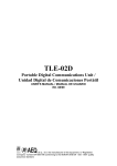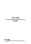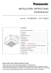
1
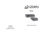
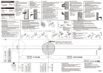
Attack Time:
compressor::
Expander/Gate:
Scalable Program Dependent
<100 usec
Release Time:
compressor:
Expander/Gate:
Scalable Program Dependent
Program Dependent
Power Requirements
15watts,100VAC 50/60Hz,120VAC 60Hz
230 VAC 50/60Hz
DIMENSIONS:
485x146x44.5mm
WEIGHT:
2.3kg
USER'S MANUAL
THRESHOLD
-20
THRESHOLD
RATIO
EXPANDER/GATE
4:1
20
15
10
6
3
THRESHOLD
1
-40
-60
-10
4:1
+10
Over
Easy
-40 dBu +20
THRESHOLD
Bypass
RATIO
:1
FAST
SLOW
ATTACK
COMPRESSOR
FAST
SLOW
RELEASE
-20
-20 dBu +20
OFF dBu +15
OUTPUT GAIN
THRESHOLD
30
RATIO
EXPANDER/GATE
4:1
20
15
10
6
3
1
0
1.3:1
-30
1:1
25
2:1
0
3:1
0
Stereo
Couple
GAIN REDUCTION dB
0
-10
2:1
-20
+10
Auto
1:1
THRESHOLD
CHANNEL TWO
0
1.3:1
-30
1:1
25
2:1
0
3:1
0 1.3:1
OFF dBu +15
30
-10
2:1
-20
GAIN REDUCTION dB
0
CHANNEL ONE
-40
-60
1.3:1
THRESHOLD
-10
4:1
+10
Over
Easy
-40 dBu +20
THRESHOLD
+10
Bypass
Auto
1:1
RATIO
:1
FAST
SLOW
ATTACK
FAST
SLOW
RELEASE
-20 dBu +20
OUTPUT GAIN
COMPRESSOR
Please read this manual carefully and proper take care of this manual
7
1. IMPORTANT SAFETY INSTRUCTIONS
4. SPECIFICATIONS
FREQUENCY RESPONSE:
Flat:
Bandwidth:
Input impedance:
Max level:
20Hz-20kHz, +0,-0.5dB
0.35Hz-80kHz, +0,-3dB
40kΩ Balancde/unbalanced
+22dBu
OUTPUT:
CAUTION:
To reduce the risk of electric shock, do not remove the top cover (or the rear section).
No user serviceable parts inside; refer servicing to qualified personnel.
WARNING: To reduce the risk of fire or electric shock, do not expose this appliance to rain and
moisture.
Impedance:
+4dBu:
-10dBV:
Max level:
This symbol, wherever it appears, alerts you to the presence of uninsulated dangerous
voltage inside the enclosure-voltage that may be sufficient to constitute a risk of shock.
This symbol, wherever it appears, alerts you to important operating and maintenance
instructions in the accompanying literature. Please read the manual.
Balanced
Balanced:
200Ω
Unbalanced: 100
Balanced:
1.5k
Unbalanced: 750
+21dBu into 600
SIDE CHAIN INSERT:
Input lmpedance:
Output lmpedance:
>10k
≤2k
Max level:
Distortion + Noise:
+21dBu
<0.2% any amount of compression at 1kHz
Intermodulation Distortion:
2<0.2% SMPTE
2. DETAILED SAFETY INSTRUCTIONS:
(1) Read these instructions.
(2) Keep these instructions.
Noise:
<-93dBu unweighted
Dynamic Range:
>114dBu unweighted
(3) Heed all warnings.
Crosstalk:
(4) Follow all instructions.
Common Mode Rejection:
>40dB (Any Frequency)
(5) Do not use this device near water.
Stereo Coupling:
(6) Clean only with a dry cloth.
(7) Do not block any ventilation openings. Install in accordance with the manufacturer s instructions.
True RMS Power Summing
Threshold Characteristics:
Selectable OverEasy or hand knee
(8) Do not install near any heat sources such as radiators, heat registers, stoves, or other apparatus (including amplifiers) that produce heat.
Exp/Gate:
(9) Do not defeat the safety purpose of the polarized or grounding-type plug. A polarized plug
has two blades with one wider than the other. A grounding type plug has two blades and a
third grounding prong. The wide blade or the third prong are provided for your safety. If the
provided plug does not fit into your outlet, consult an electrician for replacement of the obsolete outlet.
Ratio:
1
<-93dB @ 1kHz
Program Dependent Threshold
Compressor: -40 to +20dB
Expander/Gate: -60 to +10dB
Compressor: 1:1 to ∞:1
Expander/Gate: 1:1 to 4:1
6
10. Expander/Gate THRESHOLD Control and LEDs (BELOW/ABOVE)
Adjusting this control sets the level at which the gate will open and allow the signal at the
input to pass through to the output. Turning the knob fully counterclockwise (to OFF) allows the gate to pass all signals unattenuated, effectively bypassing the gate. Turning the knob fully clockwise causes the gate to attenuate input signals below +15dBu. The depth of
attenuation depends on the setting of the Expander/Gate RATIO control.
The two Expander/Gate LEDs indicate the relationship of the input signal level to the threshold setting. The red LED lights when the signal is BELOW threshold, the green LED lights when the signal is ABOVE threshold.
(10) Protect the power cord from being walked on or pinched particularly at plugs, extension
cords, and the point at which they exit the unit.
(11) Only use attachments/accessories specified by the manufacturer.
(12) Use only with the cart, stand, tripod, bracket, or table specified by the manufacturer, or
sold with the device. When a cart is used, use caution when moving the cart/ device
combination to avoid injury from stumbling over it.
11. Expander/Gate RATIO control
This control sets the amount of attenuation applide to the input signal once it is below the
threshold, from gentle downward expansion ( appropriate for mixed program, vocals, etc),
to a hard gating effect (which can be useful for percussion). Fairly low RATIO (and higher
Expander/Gate THRESHOLD) settings work best for downward expansion, whereas higher
RATIO settings (clockwise towards MAX ) work best for gating. If a setting produces undesirable pumping, readjust the Expander/Gate RATIO or THRESHOLD setting.
12. INPUT Jacks (CHANNEL one and two)
use 1/4″ phone plugs or male XLR plugs to connect these inputs to your source. The s,
ystem s INPUT jacks accept either balanced or unbalanced signals. Input impedance is
>40kΩ .
13. OUTPUT Jacks (CHANNEL one and two)
The OUTPUT jacks accept 1/4″ balanced or unbalanced phone plugs or female XLR plugs.
Maximum output signal level is >+20dBu. In the +4dBu setting, the balanced output impedance is 100Ω and the unbalanced output impedance is 50Ω . In the -10dBV setting, the b-
(13) Unplug this device during lightning storms or when not used for long periods of time.
(14) Refer all servicing to qualified service personnel. Servicing is required when the unit has
been damaged in any way, such as power supply cord or plug is damaged, liquid has been spilled or objects have fallen into the device, the unit has been exposed to rain or
moisture, does not operate normally, or has been dropped.
alanced output impedance is 1kΩ and the unbalanced output impedance is 500Ω .
14. OPERATING LEVEL Switch
3. CONTROL ELEMENTS
This switch selects between a -10dBV and +4dBu nominal operating level. When the switch is in the IN position, a -10dBV operating level is selected. When it is in the OUT position, a +4dBu operating level is selected. Note that the switch is slightly recessed. This is
to provide protection against accidental activation, possibly causing damage to other system components due to a sudden change in gain.
(6) (5)
THRESHOLD
THRESHOLD
-20
0 1.3:1
tor path. The RING acts as a Send, carrying a buffered version of te signal present at the
system INPUT jack, at an impedance of 2kΩ. The TIP acts as a Return for equipment to
feed the system s detector circuitry, such as an equalizer for de-essing or frequency-sensitive gating/compression. You can also drive the system Sidechain input with the output
of most equipment, by using a 1/4″ mono phone plug. Input Impedance is greater than
10kΩ.
16. POWER INPUT, SWITCH AND FUSE
OFF dBu +15
THRESHOLD
4:1
RATIO
(11)
15
10
6
3
1
0
-10
4:1
+10
Over
Easy
-40 dBu +20
THRESHOLD
+10
Bypass
Auto
1:1
:1
RATIO
SLOW
FAST
FAST
SLOW
RELEASE
ATTACK
Stereo
Couple
-20 dBu +20
OUTPUT GAIN
COMPRESSOR
EXPANDER/GATE
(10)
20
2:1
1.3:1
-30
1:1
25
(1)
0
3:1
15. SIDECHAIN INSERT Jack
This jack accepts 1/4″ TRS phone plugs and provides a connection to the system detec-
30
-10
2:1
-20
(4) (2)
GAIN REDUCTION dB
0
CHANNEL ONE
-40
-60
(3)
(7)
(8)
(9)
CHANNEL TWO
MAIN INPUT
SIDECHAIN
INSERT
~110V-120V 60Hz
~220V-240V 50Hz
FUSE
~110V-120V T1A
~220V-240V T500mA
POWER
OUTPUT
(16)
(13)
+4dBu
-10dBV
(14)
INPUT
TIP=INPUT
RING=OUTPUT
(12)
(15)
Power is supplied via an IEC standard 3 pin connector. The power supply fuse is located
in a fuse holder fitted into the rear panel. Always replace with the correct type and rating
of fuse, as indicated adjacent to the fuse holder.
5
2
1. STEREO COUPLE Switch and LED
This switch sets the system Stereo or Dual Mono operation. Press the STEREO COUPLE
switch in for stereo operation where Channel one becomes the master controller for both
channels. All of channel two s controls, switches, and LEDs will be disabled(except for Channel two s GAIN REDUCTION meter), since Channel two is the slave. With the STEREO
COUPLE switch out,the unit functions as two separate mono compressor/gates, each with its own independent controls.
2. BYPASS Switch and LED
Press this switch in to bypass the front panel controls, effectively canceling the function and processing effect of the compression, gating and gain settings. The input signal is still
present at the system output, but is now unaltered by the controls. BYPASS is especially
useful for making comparisons between processed and unprocessed signals. Note that with stereo operation (STEREO COUPLE switch pressed in ), the CHANNEL one BYBPASS
switch controls both channels.
3. GAIN REDUCTION (dB) Meter
This meter displays the amount of signal attenuated from the input signal by the compressor or Expander/Gate. When the compressor and Expader/gate are both active, the meter displays the maximum amoutnt of gain reduction for whichever function is greater Compressor or Expander/Gate.
4. OUTPUT GAIN (dB) Control
This control sets the overall gain of the system, from -20dB to +20dB. The OUTPUT GAIN
control is especially useful to compensate for the RMS level decrease which results from
dynamic processing effects. After you adjust the controls for the desired amount of compression, set the OUTPUT GAIN to add the same amount of gain that is shown on the GAIN
REDUCTION meters. For example, if the average amount of gain reduction shown on the
meters is 10dB, then setting the OUTPUT GAIN control to +10dB will compensate for the
10dB average level reduction at the output.
5. OVEREASY Switch
Depress this switch to select the OverEasy compression characteristic. The yellow THRESHOLD LED turns on when the signal is in the OverEasy region. When the switch is out,
the operates as a hard-knee compressor, and the yellow LED does not light.
6. Compressor THRESHOLD Control and LEDs
(BELOW/OVEREASY/ABOVE)
Adjust this control to set the threshold of compression from -40dB to +20dB. In hardknee
mode. The threshold of compression is defined as the point above which the output level
no longer changes on a 1:1 basis with changes in the input level.
In OverEasy mode the threshold of compression is defined as the middle of the OverEasy
threshold region, that is “half-way”into compression.
The three THRESHOLD LEDs indicate the relationship of the input signal level to the threshold of compression. The green LED lights when the signal is BELOW threshold, the red LED light when the signal is above threshold, and the yellow LED lights when the VOEREASY switch is depressed and the input signal is in the OVEREASY range.
The sysytm OverEasy compression permits extremely smooth, natural sounding compres-
3
Sion, without artifacts, due to the gradual change of compression around the threshold. With OverEasy compression, input signals begin to gradually activate the system internal gain change circuitry as they approach the THRESHOLD reference level. They do not get
fully processed by the RATIO, ATTACK and RELEASE controls until they have passed somewhat above the THRESHOLD reference level. As the signal level passes the THRESHOLD level, processing increases until it is fully processed to the extent determined by the control settings.
In hard-knee mode, the system can provide abrupt compression effects as well as hardlimiting applications. Note that when in hard knee mode the yellow LED will not light as the
input signal passes across the threshold. The signal is either being compressed (over threshold) or it is not being compressed (under threshold).
7. Compressor RATIO control
Adjust this control to set the amount of compression applited to the input signal. Clockwise rotation of this control increases the compression ratio from 1:1 (no compression) up
to :1 (where the compressor can be considered to be a peak limiter, especially with faster ATTACK settings).
When an input is above the THRESHOLD seting reference level, the RATIO setting determines the number of decibels by which the input signal must increase in level to produce
a 1 dB increase in the signal level at the output of the system. A setting of 2:1 indicates an
input/output ratio wherein a 2dB increase in signal (above threshold) will produce a 1 dB
increase in output signal. A setting of :1 indicates that an infinite increase in input level
would be required to raise the output level by 1 dB.
8. Compressor ATTACK and RELEASE Control
The ATTACK control sets the amount of time it takes the system to begin compressing a
signal once the detector has sensed a signal above threshold. The ATTACK range is from
FAST (for a tighter and more noticeable compression effect with very little overshoot) to
SLOW (for more delayed, gradual compression). A very fast ATTACK setting will cause the
system to act like a peak limiter even though RMS detection circuitry is used. Slower ATTACK settings cause the system to act like an RMS or averaging detecting compressor/limiter.
The RELEASE control sets how fast the compression circuit returns the input to its original level. The RELEASE rate is from FAST (where compression follows the envelope of the
program material very tightly) to SLOW (for very smooth compression).
There is no absolute right way to set the ATTACK and RELEASE controls, However, in
general, you will want them set slow enough to avoid pumping or breathing sounds caused when background sounds are audibly modulated by the dominant signal energy, yet
the release must be fast enough to avoid suppression of the desired signal after a sudden
transient or loud note has decayed. For low frequency tones (e.g., Bass guitar), set RELEASE and ATTACK to 2:00 or slower.
9. Auto Switch
This switch overrides both the ATTACK and RELEASE controls and enables preset program-dependent attack and release ,times. These times are derived from the input signal and
continuously change to match its dynamics. Enabling this AUTO Function duplicates the “
classic dbx sound” of the system s forerunners which have become standards in the industry.
4