1
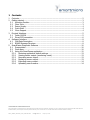
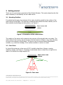
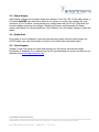
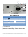
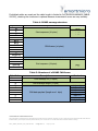
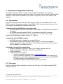
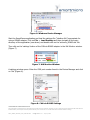
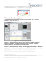
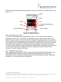
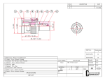
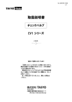
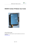
Project Documentation | Micro Radar Altimeter User Manual Project Number: SMS Project Number: Project Title: Micro Radar Altimeter Keyword(s): Micro Radar Altimeter User Manual Date: July 20, 2012 Document: Micro_Radar_Altimeter_User_Manual.docx CONFIDENTIAL AND PROPRIETARY The Information contained in this document shall remain the sole exclusive property of s.m.s smart microwave sensors GmbH and shall not be disclosed by the recipient to third parties without prior consent of s.m.s smart microwave sensors GmbH in writing. Micro_Radar_Altimeter_User_Manual.docx I Page 1 of 14 I July 20, 2012 1 Contents 1 2 Contents .................................................................................................................... 2 Getting started ........................................................................................................... 3 2.1 Mounting Position ................................................................................................ 3 2.2 Clear Zone ........................................................................................................... 3 2.3 Power Supply ....................................................................................................... 4 2.4 Quick Start .......................................................................................................... 4 2.5 Linux Support ...................................................................................................... 4 3 Physical Interface ....................................................................................................... 5 3.1 Cable-000300 ...................................................................................................... 5 3.2 Direct PCB connection .......................................................................................... 6 4 Software Interface ..................................................................................................... 8 4.1 CAN Data Description ........................................................................................... 8 4.2 RS485 Message Structure ..................................................................................... 8 5 SmartFrame Diagnostic Software .............................................................................. 10 5.1 Prerequisites ...................................................................................................... 10 5.2 Final steps ......................................................................................................... 10 5.3 Using the SmartFrame application ....................................................................... 12 5.3.1 Restoring application default settings ............................................................ 13 5.3.2 Viewing sensor output (monitoring mode) ..................................................... 13 5.3.3 Recording sensor output .............................................................................. 13 5.3.4 Replaying sensor output ............................................................................... 13 5.3.5 Exporting sensor output ............................................................................... 14 5.3.6 Uploading new firmware ............................................................................... 14 CONFIDENTIAL AND PROPRIETARY The Information contained in this document shall remain the sole exclusive property of s.m.s smart microwave sensors GmbH and shall not be disclosed by the recipient to third parties without prior consent of s.m.s smart microwave sensors GmbH in writing. Micro_Radar_Altimeter_User_Manual.docx I Page 2 of 14 I July 20, 2012 2 Getting started Thank you for purchasing a smartmicro Micro Radar Altimeter. This section describes the first steps necessary to successfully use our radar sensor. 2.1 Mounting Position For optimal performance, the antenna of the radar should be parallel to the surface of the earth during normal flight. The antenna is located directly behind the black radome, so the black surface should always be facing down, see Figure 1. Figure 1: Orientation of the radar sensor. The rotation of the sensor with respect to the yaw axis of the aircraft does not matter: The cable outlet of the housing may be pointing into the direction of flight or any other direction, as long as the radome is facing down. The sensor may be mounted behind flat plastics surfaces, e.g. inside the fuselage, if this surface contains no carbon or metal. 2.2 Clear Zone In front of the antenna, a clear zone of 150° should be kept free of large or moving reflecting objects, see Figure 2. Propellers should ideally have no direct line-of-sight to the radar or be visible at an angle beyond 90°. Radar sensor with radome 75° Clear zone 20° 3dB beam width of the antenna Figure 2: Clear zone CONFIDENTIAL AND PROPRIETARY The Information contained in this document shall remain the sole exclusive property of s.m.s smart microwave sensors GmbH and shall not be disclosed by the recipient to third parties without prior consent of s.m.s smart microwave sensors GmbH in writing. Micro_Radar_Altimeter_User_Manual.docx I Page 3 of 14 I July 20, 2012 2.3 Power Supply Valid supply voltages for the radar sensor are between 7 and 32 V DC. If the radar sensor is of revision 0Ax702 (see label at the back of the sensor) or earlier, the voltage rise time should be 15 ms or below, corresponding to a voltage slew rate of 500 V/s. Otherwise the internal voltage supervisor may trigger, disabling the sensor until powered off. Newer sensors also feature a voltage supervisor, but it disarms once the supply voltage is valid and stable. 2.4 Quick Start If you plan to use a computer to view and record sensor data, and also have bought our 000300 cable, you may skip directly to section 5 and follow the instructions there. 2.5 Linux Support Sample C code that reads the serial data stream from the sensor and extracts height information is available. It is contained on the CD accompanying the sensor and also can be obtained from [email protected] . CONFIDENTIAL AND PROPRIETARY The Information contained in this document shall remain the sole exclusive property of s.m.s smart microwave sensors GmbH and shall not be disclosed by the recipient to third parties without prior consent of s.m.s smart microwave sensors GmbH in writing. Micro_Radar_Altimeter_User_Manual.docx I Page 4 of 14 I July 20, 2012 3 Physical Interface The Micro Radar Altimeter sensor is equipped with an 8-pin male (plug) circular connector (Binder GmbH, Germany, series 712, waterproof IP67). See Table 1 for a pin-out of the sensor connector. Table 1: Sensor connector pin-out and conductor properties Pin 1 2 3 4 5 6 7 8 Function RS485 L Ground RS485 H CAN_L CAN_H not connected +7V…+32V not connected Wire color Pink = RS_485_L Blue = GND Grey = RS_485_H Yellow = CAN_L Green = CAN_H Brown = n.c. Red = Vcc (+7V…+32V) White = n.c. A female counterpart (socket) has to be used to connect to the sensor. The pin numbering of the female connector is shown in Figure 1. Figure 3: View on solder cup side of socket (rear view of female counterpart to be connected to sensor) The most common way of connecting the Micro Radar Altimeter is through our 000300 cable. It offers both CAN and RS485 connectivity and is equipped with banana plugs for power supply. 3.1 Cable-000300 Figure 4 shows a 000300 cable connected to a Micro Radar Altimeter. The red and black banana plugs are connected to a 7 … 32 V DC power supply. If your sensor is configured for RS485 output, the DSUB-9 socket labeled “RS485” is connected to a RS485 serial port of your choice, e.g. Lindy USB Serial RS485 converter. If your sensor is configured for CAN output, the DSUB-9 socket labeled “CAN” is connected to a CAN adaptor. The Binder plug is connected to the Binder socket of the sensor. For a complete pin-out of the 000300 cable see Table 2. CONFIDENTIAL AND PROPRIETARY The Information contained in this document shall remain the sole exclusive property of s.m.s smart microwave sensors GmbH and shall not be disclosed by the recipient to third parties without prior consent of s.m.s smart microwave sensors GmbH in writing. Micro_Radar_Altimeter_User_Manual.docx I Page 5 of 14 I July 20, 2012 Power CAN Cable-000300 RS485 Figure 4: CABLE-000300 Table 2: CABLE-000300 pin-out Binder plug pin numbers 1 Label CAN connector pin numbers RS485 connector pin numbers 1 Banana plugs RS485 L 2 Ground 3 5 black 3 RS485 H 4 CAN_L 2 5 CAN_H 7 2 120Ω 6 7 +7…+32V red 8 3.2 Direct PCB connection If the integrated (light) version of the Micro Radar Altimeter is used, the customer cable can be directly soldered to the printed circuit board of the UMRR, if no connector is used. The pin-out of the solder pads can be seen in Figure 5. CONFIDENTIAL AND PROPRIETARY The Information contained in this document shall remain the sole exclusive property of s.m.s smart microwave sensors GmbH and shall not be disclosed by the recipient to third parties without prior consent of s.m.s smart microwave sensors GmbH in writing. Micro_Radar_Altimeter_User_Manual.docx I Page 6 of 14 I July 20, 2012 Figure 5: Pin-out of the pads at the UMRR circuit board CONFIDENTIAL AND PROPRIETARY The Information contained in this document shall remain the sole exclusive property of s.m.s smart microwave sensors GmbH and shall not be disclosed by the recipient to third parties without prior consent of s.m.s smart microwave sensors GmbH in writing. Micro_Radar_Altimeter_User_Manual.docx I Page 7 of 14 I July 20, 2012 4 Software Interface All data communication with the Micro Radar Altimeter is handled through CAN frames. If the sensor is connected via RS485, the CAN frames are embedded into RS485 messages. Please note that in the CAN version of the sensor, RS485 result transmission is disabled and in the RS485 version of the sensor, CAN result transmission is disabled. 4.1 CAN Data Description The default CAN settings use a data rate of 500 kBaud and CAN identifier (ID) 0x750 for altimeter result transmission. Data format is “Motorola” (Big-Endian). Payload length is 8 bytes. See Table 3 for a description of the 0x750 altimeter CAN message payload. Table 3: CAN message 0x750 payload format From byte 0, byte 3, byte 6, byte 6, byte 6, bit bit bit bit bit 0 0 0 1 6 To byte byte byte byte byte 2, 5, 6, 6, 7, bit bit bit bit bit 7 7 0 5 7 Resolution 0.01 0.01 - Offset 0 0x800000 - Content altitude [m] vertical speed [m/s] altitude_valid (1 means valid) error flags (bit set to 1 means error) unused The Micro Radar Altimeter transmits other CAN messages as well, which are intended for diagnostic purposes and can be viewed using the SmartFrame program. Therefore it is not safe to assume that every CAN message contains altitude data, the CAN identifier must be regarded. 4.2 RS485 Message Structure The RS485 interface of the UMRR sensor has a predefined speed of 115200 baud/s. Data format is 1 start bit, 8 data bits, no parity, 1 stop bit. Each RS485 message begins with a start sequence of 4 bytes, followed by an arbitrary number of CAN frames, followed by an XOR checksum and an end sequence. For an overview of the RS485 message structure see Table 4. Each CAN frame transmitted via RS485 consists of the CAN identifier, the payload length and the payload itself, see Table 5. The payload format is identical to the messages transmitted via CAN and can be seen in Table 3. Please note that byte 0 of the CAN message is always transmitted last. The checksum is calculated on all data except the start sequence and the end sequence. The Checksum is a simple XOR Assignment of all n data bytes. Byte0 XOR Byte1 XOR Byte2 ... XOR Byte (n-1) CONFIDENTIAL AND PROPRIETARY The Information contained in this document shall remain the sole exclusive property of s.m.s smart microwave sensors GmbH and shall not be disclosed by the recipient to third parties without prior consent of s.m.s smart microwave sensors GmbH in writing. Micro_Radar_Altimeter_User_Manual.docx I Page 8 of 14 I July 20, 2012 If shielded cables are used and the cable length is limited to 5m (like the smartmicro CABLE000300), checking the checksum is optional because transmission errors are very unlikely. Table 4: RS485 message structure Byte Index 0 1 2 3 4+0 4+1 4+2 4+3 4+4 4+5 … 4+(n-1) 4+n 4+n+1 4+n+2 4+n+3 4+n+4 Description Start sequence (4 bytes) Fixed Value 0xCA 0xCB 0xCC 0xCD CAN frames (n bytes) XOR Checksum (1 byte) End sequence (4 bytes) 0xEA 0xEB 0xEC 0xED Table 5: Structure of a RS485 CAN frame Byte Index 0 1 2 3 4 5 6 7 8 … Description CAN message ID (2 bytes) Content MSB LSB CAN message length (1 byte) CAN data payload (length n x 1 byte) byte n-1 byte n-2 byte n-3 byte n-4 byte n-5 … byte 0 CONFIDENTIAL AND PROPRIETARY The Information contained in this document shall remain the sole exclusive property of s.m.s smart microwave sensors GmbH and shall not be disclosed by the recipient to third parties without prior consent of s.m.s smart microwave sensors GmbH in writing. Micro_Radar_Altimeter_User_Manual.docx I Page 9 of 14 I July 20, 2012 5 SmartFrame Diagnostic Software This section describes the basic usage of the SmartFrame application for displaying, recording as well as replaying radar sensor data. This version of the software supports RS485 adaptors. A CAN version is available upon request, supporting “Vector” and “Softing” CAN adaptors. 5.1 Prerequisites Prior to working with sensor data, the radar sensor needs to be connected to the PC via a RS485 converter. We suggest using the lindy RS485 to USB converter (www.lindy.com), but any converter compatible with Windows should work. Connection of the 000300 data and power cable the female Binder connector of the cable is connected to the male Binder connector of the sensor the D-SUB9 connector labeled “RS485” is connected to the RS485 converter the red and black banana plugs are connected to a 7..32 V DC power supply A photo of the cable can be seen in section 3.1, Figure 4. Connection of the RS485 converter the RS485 converter is plugged into a spare USB port If the RS485 converter is connected for the first time, a “found new hardware”window may appear. Follow instructions in that window and insert the CD that came with the adaptor, if prompted to do so. Installing the SmartFrame application Install the software on a WinXP, Vista or Win7 based computer with the “Setup_SmartFrame_Diagnostic_V058_Airborne_REG.exe” Start the software A registration window appears o send the registration request code to [email protected] o Copy the received “regNG.dat” file into the main directory of the SmartFrame application or enter the received „registration access code‟ and click „REGISTER‟. The main directory of the application is set to C:\Program Files\SmartFrame_Diagnostic_V058 by default. 5.2 Final steps Open the Windows Device Manager to find out the COM port of the newly installed RS485 adaptor (Figure 6). CONFIDENTIAL AND PROPRIETARY The Information contained in this document shall remain the sole exclusive property of s.m.s smart microwave sensors GmbH and shall not be disclosed by the recipient to third parties without prior consent of s.m.s smart microwave sensors GmbH in writing. Micro_Radar_Altimeter_User_Manual.docx I Page 10 of 14 I July 20, 2012 Figure 6: Windows Device Manager Start the SmartFrame application and load the settings file (“desktop file”) appropriate for using a RS485 adaptor: Click on File -> Load Desktop and then navigate to the main directory of the application (see above) and double-click on the „airborne_RS485.dsk‟ file. Then click on the „settings‟ button of the CAN via RS485 adaptor in the HW Monitor window. (Figure 7) Figure 7: HW Monitor Window A settings window opens. Enter the COM port number found in the Device Manager and click on „Set‟ (Figure 8). Figure 8: CAN via RS485 Settings CONFIDENTIAL AND PROPRIETARY The Information contained in this document shall remain the sole exclusive property of s.m.s smart microwave sensors GmbH and shall not be disclosed by the recipient to third parties without prior consent of s.m.s smart microwave sensors GmbH in writing. Micro_Radar_Altimeter_User_Manual.docx I Page 11 of 14 I July 20, 2012 Finally the hardware has to be re-initialized with the new settings. Click on the „reinit‟ button of the CAN via RS485 adaptor in the HW Monitor window. (Figure 9) Figure 9: HW Monitor reinit 5.3 Using the SmartFrame application The SmartFrame application features a number of (sub-)windows, nine of which are displayed by default, see Figure 10. 1 8 5 2 3 4 6 9 7 Figure 10: The SmartFrame application Window 1 is the controller window which is used to control the operating mode of the SmartFrame application. The operating mode can be either “replaying”, “recording” (including monitoring), both replaying and recording or idle. Window 2 is the hardware monitor window. The status of any supported piece of hardware is represented by a small colored rectangle. Green means “OK”, orange indicates that no data is being received and red means that the hardware has been disconnected. Window 3 is the command window used to send commands to the sensor. CONFIDENTIAL AND PROPRIETARY The Information contained in this document shall remain the sole exclusive property of s.m.s smart microwave sensors GmbH and shall not be disclosed by the recipient to third parties without prior consent of s.m.s smart microwave sensors GmbH in writing. Micro_Radar_Altimeter_User_Manual.docx I Page 12 of 14 I July 20, 2012 Window 4 is the firmware upload window. It can be used to transfer new firmware to the sensor. For historical reasons it is named “SMSDownload”. Window 5 is the video window. If video hardware is connected, it can be used to view the video stream which is being recorded or replayed. Window 6 is the data oscilloscope window. It plots the measured altitude over the time. Window 7 displays any CAN message received from the sensor DSP. Window 8 is the sensor status window. It displays the CAN output of the sensor intended for the end user. Window 9 is the CSV export window. It can be used to export sensor data into a format compatible with Matlab or Excel. 5.3.1 Restoring application default settings Program settings are stored in “desktop files”. To restore the SmartFrame default settings, click on File -> Load Desktop and then navigate to the application directory. The application directory contains a file named “airborne_RS485.dsk”, click on it and then on “open”. Do not forget to set the correct COM port afterwards, see section 5.2. 5.3.2 Viewing sensor output (monitoring mode) To view the sensor output, the monitoring mode is used. Before entering the monitoring mode, replay of any sensor data should be stopped. To stop the replay mode, switch to the replay tab of the controller window by clicking on “Replay”, then click on the stop button marked with a black square. Afterwards switch to the record tab by clicking on “Record”. The monitoring mode can be started by clicking on the “M” button. If the sensor is connected correctly, sensor data are now displayed in windows 6 through 8 and the CAN 1 status rectangle turns green in the hardware monitor window. To stop the monitoring mode, click on the stop button marked by a black square. This switches the application back to idle mode. 5.3.3 Recording sensor output When in monitoring mode, enter a file name by clicking on one of the blue floppy disk symbols in the record tab of the controller window. Then click on the button marked by a red circle to start recording. To stop recording, click on the stop once. This switches the application back to monitoring mode. 5.3.4 Replaying sensor output Make sure the monitoring mode has been stopped, and then open the replay tab of the controller window by clicking on “Replay”. Load a sensor data file by clicking on the uppermost yellow folder symbol and then navigating to the sensor data file. If a video file has been recorded as well, it is loaded automatically. Loading a set of files also works by navigating to the video file (the lowermost one), but only if video data were recorded. CONFIDENTIAL AND PROPRIETARY The Information contained in this document shall remain the sole exclusive property of s.m.s smart microwave sensors GmbH and shall not be disclosed by the recipient to third parties without prior consent of s.m.s smart microwave sensors GmbH in writing. Micro_Radar_Altimeter_User_Manual.docx I Page 13 of 14 I July 20, 2012 Once the data files have been loaded, playback can be controlled by the replay buttons, see Figure 11. faster slower pause stop play run through file as fast as possible 1 cycle backward 1 cycle forward Figure 11: replay buttons 5.3.5 Exporting sensor output CSV files can be created from recorded sensor output. At first record sensor output as described in section 5.3.3. Then check the Altimeter sensor in the sensor list of the “CSV Export” window as well as the “Export active” checkbox. Afterwards switch to the replay tab of the controller window and open a sensor output file recorded before. Click on the “run to end” (replay as fast as possible) button to perform the data export. Don‟t forget to uncheck the “Export active” checkbox once all data has been processed. The resulting .csv file is stored in the same folder as the recorded sensor output and also named the same except the .csv file name extension. An additional .txt file is created with the same name, which contains the column headers of the data. 5.3.6 Uploading new firmware Start monitoring mode and then select the new firmware file by clicking “choose file” in the View_SMSDownload window and then navigating to the appropriate file. Click “start download” to start the firmware update process. After the upload has finished, “Download successful” can be read above the progress bar. CONFIDENTIAL AND PROPRIETARY The Information contained in this document shall remain the sole exclusive property of s.m.s smart microwave sensors GmbH and shall not be disclosed by the recipient to third parties without prior consent of s.m.s smart microwave sensors GmbH in writing. Micro_Radar_Altimeter_User_Manual.docx I Page 14 of 14 I July 20, 2012