1
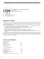
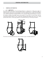
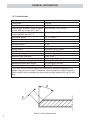
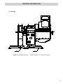
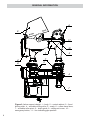
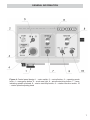
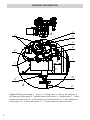
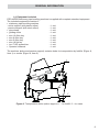
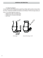
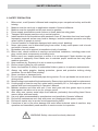
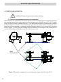
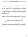
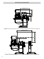
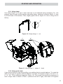
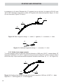
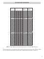
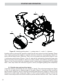
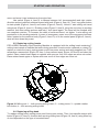
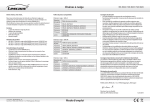
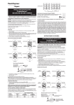
INDUSTRIAL TOOLS PRO-40PBS STATIONARY PIPE BEVELLING MACHINE OPERATOR’S MANUAL BEFORE USE, ENSURE EVERYONE USING THIS MACHINE READS AND UNDERSTANDS ALL SAFETY AND OPERATING INSTRUCTIONS IN THIS MANUAL . Serial #............................................ Date of Purchase............................ TRADEMASTER PRO-40PBS STATIONARY PIPE BEVELLING MACHINE IMPORTED & DISTRIBUTED BY INDUSTRIAL TOOL & MACHINERY SALES INDUSTRIAL TOOL T F E W 18 BUSINESS ST YATALA QLD 4207 AUSTRALIA 07 3287 1114 07 3287 1115 [email protected] www.industrialtool.com.au WARRANTY TERMS In addition to any warranties or conditions implied by applicable Statute or Regulations, Industrial Tool & Machinery Sales warrants all of it’s products against defective workmanship and faulty materials for a period of twelve (12) months from the date of purchase, unless otherwise stated. At our option we will repair or replace, free of charge, any item on the condition that: • The complete machine or tool is returned, freight prepaid to ITM or one of it’s authorised service agents as directed by ITM, and is found to have a material or constructional defect. • The machine or tool has not been subject to misuse, neglect or damage by accident. • The fault is not a result of normal “wear and tear”. • Written permission has been received from ITM prior to commencement of repair. • Repairs, tampering or modification carried out by unauthorised personnel will void all warranty. • Consumable items such as cutting tools, pilot pins, saw blades, grinding wheels etc. are NOT covered by warranty. Our goods come with guarantees which cannot be excluded under the Australian Consumer Law. You are entitled to replacement or refund for a major failure and to compensation for other reasonably foreseeable loss or damage. You are also entitled to have the goods repaired or replaced if the goods fail to be of acceptable quality and the failure does not amount to a major failure. TABLE OF CONTENTS General Information Technical Data Design Saftey Precautions Startup and Operation Wiring Diagram 2 3 4-5 6-7 8 - 11 12 Parts Lists & Exploded Views General Assembly Drive System Assembly Drive System Controller Housing Complete Panel Assembly Torch Holding & Low Torch Holding Assembly 2 13 - 14 15 16 - 17 18 19 20 GENERAL INFORMATION 1. GENERAL INFORMATION 1.1. Application The PRO-40PBS Stationary Pipe Bevelling Machine is designed for milling pipe edges of diameters from 200 mm (8’’) to 1016 mm (40’’) made of carbon steel. It performs bevelling in 0–60° angular range, bevels internal edges at 45° with maximum bevel depth of 5 mm (0.20’’) and enables facing. When equipped with one of the optional milling heads available on request, the machine enables performing J bevels with radius of 6 mm (0.24’’) or 8 mm (0.31’’) as well as bevelling internal edges in 0–60° range with maximum bevel width of 20 mm (0.79’’). Using optional steel rollers, the carrying capacity is increased 5000 kg (11 000 lbs) per support. max 5 mm (0.20'') 2 mm (0.08'') 45° threshold The value of the attained threshold will be variable for pipe of variable thickness: 3 GENERAL INFORMATION 1.2. Technical data Voltage 1~ 208-230 V, 50–60 Hz Total power 2000 W Spindle power 1500 W External pipe diameter range for pipes 200–600 mm (7.87–23.62’’) of 400–830 mm length (15.7–32.7’’) External pipe diameter range for pipes 200–1016 mm (7.87–40’’) longer that 830 mm (32.7’’) Peripheral speed 0.1–1.1 m/min Rollers rotational speed 0.1–1.2 rpm Spindle rotational speed 2800 rpm Protection level IP 20 Protection class class I Milling speed 555 m/min (1850 ft/min) Maximum bevel width b 45 mm (1.77’’, Figure 1) Bevel angle range 0–60º (ß, Figure 1) Minimum pipe thickness 5 mm (0.20’’) Active support carrying capacity 5000 kg (11 000 lbs)* Passive support carrying capacity 5000 kg (11 000 lbs)* Maximum allowed pipe weight 10 000 kg (22 000 lbs)* Machine weigth 1100 kg (2400 lbs) * For steel rollers of active support (not included in standard equipment). For plastic rollers of active support (standard), carrying capacity of each support is 3000 kg (6600 lbs) and maximum allowed pipe weight equals 6000 kg (13 200 lbs). 4 Figure 1. Bevel dimensions GENERAL INFORMATION 1.3. Design 2 1 Figure 2. Machine design: 1 – active support, 2 – passive support 5 GENERAL INFORMATION 6 9 11 10 1 2 8 5 7 3 4 7 Figure 3. Active support design: 1 – body, 2 – control cabinet, 3 – fixed driving roller, 4 – movable driving roller, 5 – scale, 6 – rollers travel lever, 7 – movable roller pivot, 8 – chain guide, 9 – milling unit cover, 10 – emergency button, 11 – line indicating pipe position 6 GENERAL INFORMATION Figure 4. Control panel design: 1 – main switch, 2 – control button, 3 – operating mode lever, 4 – emergency button, 5 – work area light, 6 – spindle start/stop button, 7 – lamp indicating spindle overload, 8 – rotator start/stop button, 9 – rotation direction switch, 10 – rotator speed adjusting knob 7 GENERAL INFORMATION 2 A 3 4 5 6 8 X 1 7 Y 10 11 A 9 Figure 5. Milling unit design: 1 – motor, 2 – milling head, 3 – milling unit lock lever, 4 – bolt securing milling head, 5 – spindle rotation lock button, 6 – angular pitch, 7 – X-axis milling unit travel crank, 8 – X-axis milling unit travel lock lever, 9 – Y-axis milling unit travel crank, 10 – Y-axis travel meter, 11 – Y-axis milling unit travel lock knob 8 GENERAL INFORMATION 1.4. Equipment included PRO-40PBS stationary pipe bevelling machine is supplied with complete standard equipment. The included equipment consists of: • stationary pipe bevelling machine - active support (with plastic rollers) – 1 unit - passive support (with steel rollers) – 1 unit • pipe clamp – 1 unit • guiding chain – 1 unit • size 10 Allen key – 1 unit • size 8 Allen key – 1 unit • size 5 Allen key – 1 unit • size 16 flat key – 1 unit • torx T15P screwdriver – 1 unit • Operator’s Manual – 1 unit The machine (active and passive support) contains holes for transportation by forklifts (Figure 6, Item 1) or cranes (Figure 6, Item 2). 2 1 Figure 6. Transportation holes (active support): 1 – for forklift, 2 – for crane 9 GENERAL INFORMATION 1.5. Optional equipment You can optionally order milling heads for performing J-bevels with the radius of 6 mm (0.24’’) or 8 mm (0.31’’) and for bevelling internal edges in 0–60° range with maximum bevel width of 20 mm (0.79’’). Additionally available steel rollers provide 5000 kg (11 000 lbs) carrying capacity per support. The optional equipment consists of: • milling head for R6 round cutting inserts • milling head for R8 round cutting inserts • milling head for bevelling internal edges • steel rollers m m 0 2 ax m threshold 8 or R 6 R J-Bevelling 10 Internal Bevelling in 0-60° SAFETY PRECAUTION 2. SAFETY PRECAUTION 1. 2. 3. 4. 5. 6. 7. 8. 9. 10. 11. 12. 13. 14. 15. 16. 17. 18. 19. 20. 21. 22. 23. 24. 25. Before start, read Operator’s Manual and complete proper occupational safety and health training. Machine must be used only in applications stated in Operator’s Manual. Machine must be complete and all parts must be genuine. Power supply specifications must conform to those stated on rating plate. Transport and operate machine only in vertical position. Install machine on flat foundations with maximum 5 mm (2’’) deviation from level over length. Improperly prepared surface may lead to damage, incorrect machine operation and may cause injuries to people in vicinity. Connect machine to installation equipped with safety circuit (earthing). Never yank power cord to disconnect plug from socket. It may cause power cord to break and result in electric shock. Bystanders can not be present in immediate vicinity of machine. Before start, check condition of machine and electrical installation, including power cord, plug, control panel components, and milling tools. Before every use, inspect machine to ensure it is not damaged. Check whether any part is cracked or improperly fitted. Make sure to maintain proper conditions that may affect machine operation. Keep machine dry. Exposing it to rain or snow is prohibited. Ensure proper lighting in your worksite. Never use machine in vicinity of combustible fluids or gases or in explosive environments. Always use safety goggles, hearing protection, gloves and protective clothing during operation. Do not wear loose clothing. Never use blunt or damaged tools. Do not touch spindle or machined pipe during motion. Do not put hands into work area of driving rollers. Mount cutting inserts and milling head securely. Remove keys and tools used for replacement. If cutting edge of insert is worn out, rotate insert in socket by 90° or, if all edges are worn out, replace with new insert specified in Operator’s Manual. Maintain machine and tools with care. Cover steel parts with thin grease layer to protect them against rust when not in use for a longer period. After every use, remove metal chips from machine, particularly from milling head. Never remove chips with bare hands. Use only parts recommended by manufacturer and specified in Operator’s Manual. Perform all maintenance work only with power cord unplugged from power socket. Perform all repairs only in service centre appointed by seller. If machine is wet or has other damage that could affect technical state of machine, stop operation and immediately send machine to service centre for inspection. WARNING: Safety rules must be closely observed. 11 STARTUP AND OPERATION 3. STARTUP AND OPERATION WARNING: Read safety precautions before starting. 3.1. Supports arrangement and machine connection Place machine on foundations that ensure balance and can transmit forces exerted by machine and working material. Use active support for machining pipes in 400–830 mm (15.7–32.7’’) length range. For pipes longer than 830 mm (32.7’’) use also passive support, positioning it in relation to active support in a manner that prevents pipe from moving during rotation. This can be done either by ensuring equality of diagonals formed between supports or by using 55x15 drawing flat bar (Figure 7). Every support contains holes for fastening to foundations. We recommend to connect the machine into mains using 3G2.5 mm2 power cord. X 55x15 drawing flat bar X Figure 7. Supports arrangement for bevelling pipes longer than 830 mm (32.7’’) 12 STARTUP AND OPERATION 3.2. Operating modes The machine can operate in rotator or beveller mode, set by lever (Figure 4, Item 3). Rotator mode enables to start rollers with green button (Figure 4, Item 8) and to adjust rotational speed using knob (Figure 4, Item 10). Spindle rotation is inactive in this mode. Beveller mode enables, after closing cover (Figure 3, Item 9), to start the spindle using green button (Figure 4, Item 6) and then to start rollers (Figure 4, Item 8). If the spindle gets overloaded during operation, red light will illuminate (Figure 4, Item 7). In such case, immediately decrease either milling depth or rotational speed of rollers. To decrease milling head penetration in the working material, retract Y-axis milling unit using crank (Figure 5, Item 9). Further spindle load increasing will trigger safety circuit and shut down the rotator (spindle rotation will not stop). In such case, before you start rollers again, retract Y-axis milling unit and press rotator stop red button (Figure 4, Item 8). This will turn off the red lamp and enable to start rotator with green start button (Figure 4, Item 8). If the cover becomes open during bevelling, spindle and rotator will immediately stop operation. 3.3. Placing pipe Before you place the pipe on the machine, set movable driving rollers (Figure 3, Item 4) to match the red line (Figure 3, Item 11) with machined pipe diameter on the scale (Figure 3, Item 5). For this purpose, remove pivots (Figure 3, Item 7), maximally lower rollers travel lever (Figure 3, Item 6) and use it to manually move rollers forwards or backwards. Once setting in proper position, raise lever and reinsert pivots. Proceed as described for passive support as well (Figure 2, Item 2). WARNING: Before you place the pipe, raise cover (Figure 3, Item 9) and use crank (Figure 5, Item 7) to lower X-axis milling unit to prevent its damage caused by collision with the pipe. Place the pipe on the rotator to maintain a 160–260 mm (6–10’’) distance between pipe face and side surface of the rollers on the active support, as in Figure 9. Because position of machining differs from position of the support, any pipe shape tolerance deviation will cause inconsistency in the bevel or threshold. To diminish these errors, place the pipe as close to the rollers as permitted (160 mm, 6’’). Additionally, you may need to use clamp, guiding chain, or both. 13 STARTUP AND OPERATION O 600 mm (23.6'') 830 mm (32.7'') O 200 mm (7.9'') 400 mm (15.7'') Figure 8. Placing pipe with the length of 400–830 mm and maximum diameter of Ø600 mm 160-260 mm (6-10'') O200-1000 mm (7.9-39.4'') over 830 mm (32.7'') Figure 9. Placing pipe longer than 830 mm with maximum diameter of Ø1000 mm 14 STARTUP AND OPERATION 3.3.1. Using clamp Use clamp (Figure 10) if pipe is short and light or not balanced during machining. For this purpose, place the pipe on the machine and mount clamp, catching it by hooks (Figure 11, Item 2) at both sides of the machine. Then, slightly tighten the nut (Figure 10, Item 1) using size 16 flat key. 1 Figure 10. Clamp design: 1 - nut 1 2 Figure 11. Using clamp: 1 – clamp, 2 – hook 3.3.2. Using guide chain If pipe moves along its axis during milling, use guiding chain to provide balance. To create the chain for the pipe of specific external diameter, use basic “B” segment (Figure 12) and 3-, 6-, 9-, 18-, 36-, 72-link additional segments (Figure 13). Their proper interconnection sequence to form a single chain is shown in Table 1 (columns from left to right), while basic “B” segment 15 STARTUP AND OPERATION is necessary in all cases. Because the “3” segment can not be last, for pipes in 223–251 mm (8.78–9.88’’) diameter range place it within “B” segment after dismounting links (Figure 12, Item 4) from connector (Figure 12, Item 3). 2 1 3 4 Figure 12. Basic segment design: 1 – catch, 2 – tightener, 3 – connector, 4 – links 2 1 Figure 13. Additional segments design: 1 – connector, 2 – links 3.3.3. Guide chain usage example To create guiding chain for pipe with external diameter of 390 mm (15.35’’), connect basic “B” segment to additional “18” and “3” segments using connectors (Figure 13, Item 1) with the help of size 5 Allen key. Proper interconnection sequence should be as follows: “B”, “3”, “18” (Figure 14). 1 2 3 Figure 14. Guiding chain design for pipe with external diameter of 390 mm (15.35’’):1 – basic segment, 2 – 3-link segment, 3 – 18-link segment 16 STARTUP AND OPERATION Basic segment Additional segments Pipe external diameter range [mm] Pipe external diameter range [in] B – – – – 199–227 7.83–8.94 B 3 – – – 223–251 8.78–9.88 B 6 – – – 248–275 9.76–10.83 B 9 – – – 272–300 10.71–11.81 B 3 9 – – 296–324 11.65–12.76 B 6 9 – – 320–348 12.60–13.70 B 18 – – – 345–372 13.58–14.65 B 3 18 – – 369–397 14.53–15.63 B 6 18 – – 393–421 15.47–16.57 B 9 18 – – 417–445 16.42–17.52 B 3 9 18 – 442–469 17.40–18.46 B 6 9 18 – 466–494 18.35–19.45 B 36 – – – 490–518 19.29–20.39 B 3 36 – – 514–542 20.24–21.34 B 6 36 – – 539–566 21.22–22.28 B 9 36 – – 563–591 22.17–23.27 B 3 9 36 – 587–615 23.11–24.21 B 6 9 36 – 611–639 24.06–25.16 B 18 36 – – 636–663 25.04–26.10 B 3 18 36 – 660–688 25.98–27.09 B 6 18 36 – 684–712 26.93–28.03 B 9 18 36 – 708–736 27.87–28.98 B 3 9 18 36 733–760 28.86–29.92 B 6 9 18 36 757–785 29.80–30.91 B 72 – – – 781–809 30.75–31.85 B 3 72 – – 805–833 31.69–32.80 B 6 72 – – 830–858 32.68–33.78 B 9 72 – – 854–882 33.62–34.72 B 3 9 72 – 878–906 34.57–35.67 B 6 9 72 – 903–930 35.55–36.61 B 18 72 – – 927–955 36.50–37.60 B 3 18 72 – 951–979 37.44–38.54 B 6 18 72 – 975–1003 38.39–39.49 B 9 18 72 – 1000–1027 39.37–40.43 Table 1. Proper segments interconnecting sequence for specific pipe diameters Before placing pipe on the machine, place guiding chain between driving rollers (Figure 3, Item 4). Then, place the pipe and hook up the chain on pipe perimeter as shown in Figure 15. 17 STARTUP AND OPERATION 1 A 3 A 2 Figure 15. Installing guiding chain: 1 – guiding chain, 2 – catch, 3 – tightener Hook the catch on the last link, second or third from the end, and put free links upwards (Figure 15a). Tighten guiding chain slightly to maintain minimum clearance, using tightener (Figure 15, Item 3) with the help of size 10 Allen key. Then, turn on the power with main switch (Figure 4, Item 1) and press control button (Figure 4, Item 2), what will be indicated by illuminating lamp after about 5 seconds. Set lever (Figure 4, Item 3) to “rotator” position, start rotation using green button (Figure 4, Item 8) and perform one complete rotation to ensure good arrangement of the guiding chain. Then, stop rotator with red button (Figure 4, Item 8) and tighten guiding chain completely. 3.4. Spindle setup and machine startup To perform a bevel, open milling unit cover (Figure 3, Item 9). Then, after loosening levers (Figure 5, Item 3), set milling unit to required angle on the pitch (Figure 5, Item 6) and lock its rotation with the button (Figure 5, Item 5). Unlock X axis milling unit travel lever (Figure 5, Item 8), move milling unit to proper height using crank (Figure 5, Item 7) and lock again (Figure 5, Item 8). Set crank in horizontal position and fold its handle to prevent collision with the cover. Then, close the 18 STARTUP AND OPERATION cover and move it two inches away from pipe face. Use switch (Figure 4, Item 9) to choose between left (recommended) and right rotator direction and set required rotational speed with knob (Figure 4, Item 10). Then, use green button to start spindle (Figure 4, Item 6) and rotator (Figure 4, Item 8). Unlock Y axis milling unit travel using knob (Figure 5, Item 11). Rotating crank (Figure 5, Item 9), bring the tool close to working material, then start milling process and lock Y axis travel again. The bevel will be finished after one complete rotation. To increase the width of achieved bevel, set higher Y axis milling unit penetration in the working material. In case of emergency, press one of the emergency buttons: either located on the machine body (Figure 3, Item 10) or on the control panel (Figure 4, Item 4), what will shut down the power. 3.5. Replacing cutting inserts PRO-40PBS Stationary Pipe Bevelling Machine is equipped with the milling head containing 7 cutting inserts made of carbide that wear during operation. Inserts can be replaced or rotated. To replace or rotate the insert, unplug power cord from power socket and using supplied torx T15P screwdriver unscrew bolt (Figure 16, Item 1), then remove insert (Figure 16, Item 2) and clean the socket. Place rotated insert again or replace with new one if all four edges are worn out.socket. Place rotated insert again or replace with new one if all four edges are worn out. 2 1 4 3 Figure 16. Milling tool: 1 – bolt securing cutting insert, 2 – cutting insert, 3 – spindle rotation lock button, 4 – bolt securing milling head 3.6. Replacing milling head To replace milling head, unplug power cord from power socket. Then, lock spindle rotation with button (Figure 16, Item 3), unscrew bolt securing milling head (Figure 16, Item 4) using Allen key of size dependent on the type of mounted head. 19