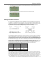
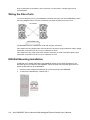
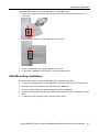
1
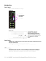
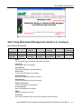
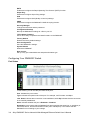
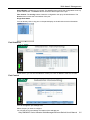
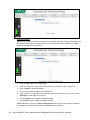
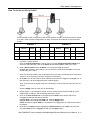
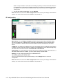
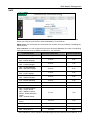
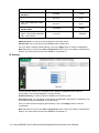
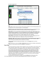
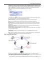
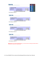
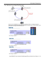
Alloy RMS602F Series Industrial Ethernet DIN Rail Switch User’s Manual First Edition, May 2005 www.alloy.com.au Alloy RMS602F Series Industrial Ethernet Din Rail Switch User’s Manual Copyright Notice Copyright © 2005 Alloy Computer Products. All rights reserved. Reproduction in any form or by any means without permission is prohibited. Table of Contents Chapter 1 Introduction .............................................................................................1-1 Overview........................................................................................................... 1-2 Ethernet Switching Technology ........................................................................ 1-2 Product Features .............................................................................................. 1-2 Package Checklist ............................................................................................ 1-3 Chapter 2 Hardware Installation ..............................................................................2-1 Introduction....................................................................................................... 2-2 Panel Layout ....................................................................................................... 2-2 Reset Button ....................................................................................................... 2-2 LED Indicators..................................................................................................... 2-2 DIP Switch........................................................................................................... 2-4 Wiring the Power Inputs ................................................................................... 2-4 Wiring the Relay Output ................................................................................... 2-4 Wiring the Ethernet Ports ................................................................................. 2-5 Wiring the Fibre Ports ....................................................................................... 2-6 DIN-Rail Mounting Installation .......................................................................... 2-6 Wall-Mounting Installation................................................................................. 2-7 Chapter 3 Web-based Management ........................................................................3-1 Introduction....................................................................................................... 3-2 Preparation for Web Management.................................................................... 3-2 System Login.................................................................................................... 3-2 Start Using Web-based Management Interface to Configure ........................... 3-3 Menu Bar Introduction......................................................................................... 3-3 Configuring Your switch....................................................................................... 3-4 Chapter 4 Troubleshooting ......................................................................................4-1 Incorrect Connections....................................................................................... 4-2 Faulty or Loose Cables ....................................................................................... 4-2 Non-standard Cables .......................................................................................... 4-2 Improper Network Technologies ......................................................................... 4-2 LED Indicators .................................................................................................. 4-2 Appendix A Specifications......................................................................................... A-1 1 Chapter 1 Introduction Welcome to the Alloy RMS602F Series Industrial Ethernet Rail Switch. The RMS602F Series is a web-managed rail switch that is specially designed for industrial applications. The following topics are covered in this chapter: Overview Ethernet Switching Technology Product Features Package Checklist Installation Guide Overview The RMS602F Series are a web-managed rail switch that is specially designed for industrial applications. Alloy use a one-piece formed aluminum case that complies with IP31 industrial standards, allowing the RMS602F to operate under harsh industrial environments. The RMS602F provides dual DC power inputs, ensuring your systems maximum up-time. The RMS602F also supports Super Ring technology, which can provide you with industrial-grade network redundancy. When your primary path fails, the entire system can still function normally with auto-failover to a secondary path. The RMS602F supports longer distance and more secure connections with direct fibre termination. An easy to use Web-based management interface provides simple and efficient network Management. Ethernet Switching Technology Ethernet Switching Technology dramatically boosts the total bandwidth available to your network. It eliminates congestion problems inherent with CSMA/CD (Carrier Sense multiple access with Collision Detection) protocols, and greatly reduces unnecessary transmissions. Switching revolutionised networking firstly by allowing Full-duplex operation, which essentially doubled the bandwidth available on the same network connection. Secondly, switching also reduced the collision domains to a single switch-port, this eliminated the need for carrier sensing. And lastly, by using store-and-forward switching technology to inspect each packet to intercept corrupt or redundant data, switching eliminated unnecessary transmissions that caused network performance problems. Auto-negotiation regulates the connection speed and duplex of each port, based on the capability of both devices. Flow-control allows transmission from a 100Mbps node to a 10Mbps node without loss of data. In certain legacy environments you may need to disable Auto-negotiation and flow-control to ensure compatibility. Disabling the auto-negotiation is accomplished by fixing the speed and/or duplex of a port. Product Features Alloy RMS602F Series products have the following features: Redundant Ethernet Super Ring Support VLAN, QoS and IGMP Snooping Web-based Configuration Redundant DC Power Inputs Alarm Relay Output Robust Aluminum case, IP31 standard DIN-Rail/Wall-mounting/Desktop Installation 6 10/100TX ports and 2 100FX port(s) Conforms to IEEE 802.3 10Base-T, 802.3u 100Base-TX/100Base-FX RJ-45 ports support auto MDI/MDI-X function Store-and-Forward switching architecture Web management GUI Provides fibre link ability IEEE 802.3x flow control supported ¾ 1-2 Flow control on full-duplex mode Alloy RMS602F Series Industrial Web-Managed Ethernet Switch User’s Manual Introduction ¾ Back pressure on half-duplex mode Supports Class of Service Supports IGMP with Query mode for multi media application Supports broadcast packet filtering Supports SNTP Provides reverse polarity protection 1Mbits embedded memory 2K MAC address table Supports port-based VLAN / 802.1 Q Tag VLAN Package Checklist Alloy RMS602F Series products are shipped with the following items: 1 Industrial Web-Managed Ethernet DIN Rail Switch One DIN-Rail clip One wall mounting plate and six screws Documentation and Software CD If any of the above items is missing or damaged, please contact your local sales representative. Alloy RMS602F Series Industrial Web-Managed Ethernet Switch User’s Manual 1-3 2 Chapter 2 Hardware Installation This chapter includes information on installation and configuration of your Industrial Switch. The following topics are covered in this chapter: Introduction ¾ Panel Layout ¾ Reset Button ¾ LED Indicators ¾ DIP Switch Wiring the Power Inputs Wiring the Relay Output Wiring the Ethernet Ports Wiring the Fibre Ports DIN-Rail Mounting Installation Wall-Mounting Installation Introduction Panel Layout Here we use the RMS602F as an example. Front View 1 Fibre Ports 2 LED indicators 3 DIP switch 4 RJ-45 ports Bottom View The Side/Bottom view of the RMS602F Series Industrial Web-Managed Ethernet DIN Rail Switch consists of one terminal block connector with two DC power inputs, alarm input and one DC IN power jack for an additional AC/DC power adapter. Reset Button The Reset button provides users with a quick and easy way to restart the switch and if required, restore the default settings. To restart: press the Reset button for 2 seconds and release. To restore the default settings: press the Reset button for 5 seconds and release. LED Indicators There are 9 diagnostic LEDs and 12 Port LEDs located on the front panel of the RMS602F Industrial Ethernet Rail Switch. These LED indicators provide administrators with real-time system status. Table 1 gives a description of the function of each LED indicator. 2-2 Alloy RMS602F Series Industrial Web-Managed Ethernet Switch User’s Manual Hardware Installation LED PWR PWR 1 PWR 2 Status Description Green Power is on. Off No power is being supplied. Green Power is on. Off No power is being supplied. Green Power is on. Off No power is being supplied. Green Indicates that this Unit is the master in a Super Ring topology. Off Indicates that this Unit is NOT the master in a Super Ring topology. Yellow Power, or UTP port, or fiber port failure occurs. Off No power, or UTP port, or fiber port failure occurs. Status Description Green A network device is detected. Blinks The port is transmitting or receiving packets from the TX device. Off No device is attached. Orange The port is operating in full-duplex mode. Blinks Collision of packets is occurring. Off The port is in half-duplex mode or no device is attached. Green A network device is detected. Blinks The port is transmitting or receiving packets from the TX device. Off No device is attached. Orange The port is operating in full-duplex mode. Blinks Collision of packets is occurring. Off The port is in half-duplex mode or no device is attached. Orange The port is operating in full-duplex mode. Blinking orange Collision of packets is occurring. Off The port is in half-duplex mode or no device is attached. Green A network device is detected. Blinking green The port is transmitting or receiving packets from the TX device. Off No device is attached. R.M Fault Port LED LNK/ACT of Port 7 (RMS602F) FDX/COL of Port 7 (RMS602F) LNK/ACT of Port 8 (RMS602F) FDX/COL of Port 8 (RMS602F) Copper Port Status (Ports 1 – 6) Alloy RMS602F Series Industrial Web-Managed Ethernet Switch User’s Manual 2-3 DIP Switch The DIP switch is used to configure which unit in a Super Ring is to be the master switch. DIP SWITCH Status R.M. P1 to P8 (RMS602F) Description ON Set this switch to be the Ring Master. Off Set this switch NOT to be the Ring Master. ON To enable port break alarm on each port. Off To disable port break alarm. Wiring the Power Inputs 1. Insert the positive and negative wires into the V+ and V- contact on the terminal block connector. 2. Tighten the wire-clamp screws to prevent the DC wires from being loosened. Note: The suitable electric wire ranges from 12 to 24 AWG. Note: The additional power jack is designed for office use. Wiring the Relay Output The relay output alarm contacts are in the middle of the terminal block connector as shown in the figure below. By inserting the wires and setting the DIP switch to “ON”, the relay output will activate (Close) on detection of a power or port failure. The figure below illustrates an example of how the relay output alarm works. Note: The alarm relay output only provides an Open / Closed Connection circuit. It does not supply any power. The relay controlling this can be used to switch 1A @ DC 24Volts max. Fault Alarm Contact The circuit will close in a power failure or port link failure condition. 24V DC Buzzer 24V Battery Use a Buzzer or Strobe light to indicate a Fault Condition 2-4 Alloy RMS602F Series Industrial Web-Managed Ethernet Switch User’s Manual Hardware Installation 1. Insert the alarm device’s negative wire into assigned position of the terminal block connector. 2. Tighten the wire-clamp screws to prevent the wires from being loosened. Wiring the Ethernet Ports RJ-45 ports with auto MDI-MDI-X function: RMS602F has six 10/100 Mbps auto-sensing ports for 10Base-T or 100Base-TX device connection. The UTP ports will auto-detect 10Base-T and 100Base-TX connections. The auto MDI/MDI-X function allows users to connect another switch or workstation without worry about straight-through or cross-over cabling types. See the diagrams below for the pin layout of straight-through and cross-over cabling. Straight-through Cabling Schematic Cross-over Cabling Schematic Use twisted-pair Category 5 cables for RJ-45 port connection. Connect one side of an Ethernet cable into the RMS602F TX port, while the other side is connected to the attached device. The Link LED will light up when the cable is correctly connected. Refer to the LED Indicators section for descriptions of the various function of each LED indicator. The cables between the RMS602F and the attached device (e.g. switch, hub, or workstation) must be less than 100 meters (328 ft). All copper ports of the RMS602F support the auto-MDI/MDI-X function. When you use an Ethernet cable to connect other devices, such as computers, switches or hubs, pin 1, 2, 3, and 6 of the 8-pin RJ45 connector are used to communicate with the connected devices. Pin 1, 2, 3 and 6’s signals are converted by the MDI-X function, as shown in the table below. Pin MDI-X Signals MDI Signals 1 RD+ TD+ 2 RD- TD- 3 TD+ RD+ 6 TD- RD- When re-linking or moving connected devices between the RJ-45 ports you need to allow time for the MAC address table to drop and re-learn the attached nodes. This period of time is called MAC address table aging time. RMS602F default aging time is 5 minutes, which means that if you manually change the up-link port, you will need to wait for 5 minutes before the data can be sent. If the aging time is too short, the MAC address table will constantly refresh, resulting in Alloy RMS602F Series Industrial Web-Managed Ethernet Switch User’s Manual 2-5 large consumption of the switch’s CPU resources. For this reason, a longer aging time is recommended. Wiring the Fibre Ports To connect the fibre port on your RMS602F to another fibre port on a second RMS602F, follow the wiring diagram below. Incorrect connection will cause the fibre ports not to work. The RMS602F has two 100Base-FX ports with SC type connectors. Fibre segments using single mode must use 8/125 or 9/125 μm single-mode fibre cables. Single mode fibre connections can be run up to a distance of 30 km. Fibre segments using multi mode must use 50 or 62.5/125 μm multi-mode fibre cables. Multi mode fibre connections can be run up to a distance of 2 km. DIN-Rail Mounting Installation A DIN-Rail clip is already attached to the RMS602F Series product when packaged. If the DIN-Rail clip is not screwed on the RMS602F, follow the instructions and the figure below to attach the DIN-Rail clip to the RMS602F. 1. Use the screws to attach the DIN-Rail clip to the rear panel of the RMS602F. 2. To remove the DIN-Rail clip, reverse step 1. 2-6 Alloy RMS602F Series Industrial Web-Managed Ethernet Switch User’s Manual Hardware Installation Follow the steps below to mount the RMS602F to the DIN-Rail track. 1. First, insert the upper end of the DIN-Rail clip into the back of the DIN-Rail track from its upper side. 2. Lightly push the bottom of the DIN-Rail clip into the track. 3. Check if the DIN-Rail clip is tightly attached on the track. 4. To remove the RMS602F from the track, reverse the steps above. Wall-Mounting Installation Follow the steps below to install the RMS602F with the wall mounting plate. 1. To remove the DIN-Rail clip from the RMS602F, loosen the screws from the DIN-Rail clip. 2. Place the wall mounting plate on the rear panel of the RMS602F. 3. Use the screws to tighten the wall mounting plate onto the RMS602F. 4. Use the hook holes at the corners of the wall mounting plate to hang the RMS602F onto the wall. 5. To remove the wall mounting plate, reverse the steps above. Alloy RMS602F Series Industrial Web-Managed Ethernet Switch User’s Manual 2-7 2-8 Alloy RMS602F Series Industrial Web-Managed Ethernet Switch User’s Manual 3 Chapter 3 Web-based Management This chapter includes information about how to configure and manage your RMS602F via the web-based interface. The following topics are covered in this chapter: Introduction Preparation for Web Management System Login Start Using the Web-based Management Interface to Configure your RMS602F ¾ Menu Bar Introduction ¾ Configuring Your RMS602F Introduction The RMS602F implements an embedded HTML web-server to provide users with a complete HTML management interface from anywhere on the network, via any standard web browser such as Microsoft Internet Explorer. The web-based management interface supports Internet Explorer 5.0. It is based on Java Applets with an aim to reduce network bandwidth consumption, to enhance the access speed, and to offer an easy-to-use management screen. Note: IE 5.0 or any later version does not allow Java Applets to open sockets by default. Users have to directly modify the browser settings to enable Java Applets to use network ports. Preparation for Web Management Before you start to use the Web-based management interface to manage your RMS602F, make sure that the RMS602F is properly installed on your network, and that every PC on the network can link to the RMS602F via the web browser. 1. Make sure your network card is working normally, your IP address is assigned correctly, and your operating system supports the TCP/IP protocol. 2. Connect the RMS602F’s DC power input to a DC power source. 3. Connect your computer to the RMS602F via one of the RJ-45 ports. 4. Make sure that the RMS602F’s default IP address is 192.168.0.100 (you can confirm the default IP of the switch from the Label on the side of the switch) 5. Change your computer’s IP address to 192.168.0.2 6. Switch to DOS command mode, and test the connectivity to the switch via the ”ping 192.168.0.100” command. Make sure that the ping response time is normal. (less than 10msec) System Login 1. Launch Internet Explorer on the PC. 2. Type http:// and the IP address of the RMS602F. And then press Enter. 3. The login screen will appear next. 4. Key in the user name and the password. The default user name and the password is admin. 5. Click on Enter or OK, and then the homepage of the web-based management interface will appear. 6. Once you enter the web-based management interface, change the RMS602F’s IP address to fit your network environment. 3-2 Alloy RMS602F Series Industrial Web-Managed Ethernet Switch User’s Manual Web-based Management Start Using Web-based Management Interface to Configure Menu Bar Introduction Home Port Status Port Statistics IP Security Port Control IP SNTP Configuration Security Configuration TFTP Update Manager Backup Firmware Port Mirroring RSTP Switch Settings Super Ring Factory Default Save Configuration System Reboot QoS VLAN Configuration IGMP Rate Control Home The homepage of the web-based management interface. Port Status Displays port status and settings. Port Statistics Displays the RMS602F’s port data statistics. Port Control Configure the RMS602F’s port settings. Switch Settings Display’s the RMS602F system information. Port Mirroring Enable and configure port mirroring settings. VLAN Configuration Enable and configure VLAN settings. IP Configuration Set up the RMS602F’s IP address. SNTP Enable the network time server. IP Security Set up the IP addresses from which web management will be allowed. Alloy RMS602F Series Industrial Web-Managed Ethernet Switch User’s Manual 3-3 RSTP Enable and configure the Rapid Spanning Tree Protocol (RSTP) function. Super Ring Enable and configure Super Ring settings. QoS Enable and configure QoS (Quality of service) settings. IGMP Enable and configure the RMS602F’s IGMP Snooping function. Security Manager Change the username and the password. Configuration Backup Backup the RMS602F’s settings to a file on your PC. TFTP Update Firmware Use a TFTP utility to update to the latest firmware on the RMS602F. Factory Default Restore the factory default settings. Save Configuration Save the RMS602F’s settings. System Reboot Reboot the RMS602F. Rate Control Set up every port’s bandwidth rate and packet limitation type. Configuring Your RMS602F Switch Port Status In this window, you can see the port status of all ports. Port: indicates the port number. Type: indicates the speed mode of the port. For example, 100TX means 100 Mbps. Link: Down indicates that connection is not established, while Up indicates that the connection is successfully established. State: indicates whether this port is Enabled or Disabled. Negotiation: Auto means that the RMS602F will auto-negotiate the speed (10 or 100 Mbps) of the remote device, and the transmission mode (full or half duplex). Force means that the RMS602F runs according to your settings. 3-4 Alloy RMS602F Series Industrial Web-Managed Ethernet Switch User’s Manual Web-based Management Speed Duplex: indicates the port speed. The Config column shows the configuration as set up by the administrator. The Actual column shows the actual speed of the port. Flow Control: The Config column shows the configuration set up by the administrator. The Actual column shows the actual status of the port. Single Port Status You can directly click on any port on the panel display on the left side to see its information. Port Statistics In this section, you can see the statistics of each port. Click on Clear to reset the counters. Port Control You can change the port settings here. Select the port you want to configure. You will see the current settings and status of the selected port. Alloy RMS602F Series Industrial Web-Managed Ethernet Switch User’s Manual 3-5 In the State column, you can enable or disable any selected port. In the Negotiation column, you can configure the auto negotiation mode to Auto, Nway (to specify the speed/duplex on this port and enable auto-negotiation), or Force. In the Speed column, you can configure the speed of this port. In the Duplex column, you can configure the full-duplex or half-duplex mode of this port. In the Flow Control column, you can enable or disable the Flow Control function by selecting ON or OFF for the Full Duplex mode. Once you finish configuring the settings, click on Apply to save the configuration. Note: Remember to click on the Save Configuration button to save your settings. Otherwise the settings you made will be lost when the RMS602F is powered off. Switch Settings You can assign the system name, location, and view the system information. System Name: you can assign a name to the RMS602F. System Location: you can specify the RMS602F’s physical location. System Description: you can briefly describe the RMS602F (its purpose or application). Firmware Version: this information shows the firmware version on the RMS602F. Kernel Version: this information shows the kernel version on the RMS602F. Hardware Version: this information shows the hardware version of the RMS602F. MAC Address: this information displays the unique hardware address assigned by the manufacturer (the default setting). Once you finish configuring the settings, click on Apply to save the configuration. Note: Remember to click on the Save Configuration button to save your settings. Otherwise the settings you made will be lost when the RMS602F is powered off. 3-6 Alloy RMS602F Series Industrial Web-Managed Ethernet Switch User’s Manual Web-based Management Port Mirroring Port mirroring is a method for you to monitor traffic in a switched network. Traffic through ports can be monitored by one specific port. This emulates the shared media feature that was utilised in hub/repeater technology. Port Mirroring State: Defines the mirroring mode, Disable, RX, TX, and Both. Analysis Port: Defines which port will receive the mirrored data from the selected monitored ports. This port is normally connected to a LAN analyzer. Monitor Port: These are the ports you want to monitor from the Analysis port. Traffic from monitored ports will be copied to the mirror port (Analysis port). Once you finish configuring the settings, click on Apply to save the configuration. Note: If you want to disable this function, select the monitor port to none. Note: Remember to click on the Save Configuration button to save your settings. Otherwise the settings you made will be lost when the RMS602F is powered off. VLAN Configuration A Virtual LAN (VLAN) is a logical network that limits the broadcast domain. It allows you to isolate network traffic so that only members of the VLAN will receive traffic from the same VLAN members. Basically, creating a VLAN from a switch is logically equivalent of reconnecting a group of network devices to another Layer 2 switch. However, all the network devices are still plugged into the same switch physically. RMS602F Series switch supports both port-based and 802.1Q (tagged-based) VLAN. The VLAN mode is “disabled” by default. Alloy RMS602F Series Industrial Web-Managed Ethernet Switch User’s Manual 3-7 Port-based VLAN Packets only go to the members of the same VLAN groups. Note that all of the unselected ports are treated as belonging to another single VLAN. If port-based VLAN is enabled, any tagged based VLAN settings will be ignored. 1. Click on Add to add a new VLAN group. 2. Enter the VLAN name, group ID, and then select the members for this VLAN group. 3. Click on Apply to adopt the settings. 4. The switch should now display your VLAN group. 5. If the groups list is longer than can be viewed in the vertical column, then you can click on Next Page to view other VLAN groups. 6. Use the Delete button to delete unwanted VLAN’s. 7. Use the Edit button to modify the existing VLAN’s. Note: Remember to click on the Save Configuration button to save your settings. Otherwise the settings you made will be lost when the RMS602F is powered off. 3-8 Alloy RMS602F Series Industrial Web-Managed Ethernet Switch User’s Manual Web-based Management 802.1Q VLAN Tag-based VLAN is an IEEE 802.1Q standard. Therefore, it is possible to create a VLAN across different vendor switches. IEEE 802.1Q Frame Tagging technology will insert a “tag” into the Ethernet frames. The tag contains a VLAN Identifier (VID) that indicates which VLAN this frame belongs to. The switch only interrogates the frame’s VLAN tag header, and does not need to process the complete frame to make its VLAN forwarding decisions. This minimizes the switches CPU loading, but also enables enterprise VLAN capabilities. Basic 1. Click on Add button to add a new VLAN. 2. Group Name: Enter a name for the new VLAN. 3. VLAN ID: Enter a VLAN ID (the value can be between 2 and 4094). The default value is 1. 4. Select the required ports from the available ports box and click on Add to add to them the RMS602F VLAN group. Then click on Next to continue. Alloy RMS602F Series Industrial Web-Managed Ethernet Switch User’s Manual 3-9 5. Now you define if the outgoing frames are to be VLAN-Tagged frames or untagged frames. Click on Apply to save the settings. Tag: indicates that outgoing frames are VLAN-Tagged. Untag: indicates that outgoing frames are not VLAN-Tagged. Port VID Port VLAN ID: Defines the port VLAN ID that incoming packets are allocated (if not already a member of a tagged VLAN group). This is a VLAN identify for use by the switch inside the RMS602F only. Once you finish configuring the settings, click on Apply to save the configuration. Note: Remember to click on the Save Configuration button to save your settings. Otherwise the settings you made will be lost when the RMS602F is powered off. 3-10 Alloy RMS602F Series Industrial Web-Managed Ethernet Switch User’s Manual Web-based Management How To Set Up an 802.1q VLAN? In this example we will configure PC1 and PC3 to reside on VLAN 2 and PC2 and PC4 to reside on VLAN 3. After we have configured the VLAN’s, VLAN 2 will be unable to communicate with VLAN 3. Switch 1 Switch 2 Port Connecting Device VLAN Group PVID Tag/Untag Port Connecting Device VLAN Group PVID Tag/Untag 1 PC1 2 2 Untagged 1 PC3 2 2 Untagged 2 PC2 3 3 Untagged 2 PC4 3 3 Untagged 8 Switch 2 2, 3 1 Tagged 8 Switch 1 2, 3 1 Tagged 1. On switch 1 create VLAN 2. Click on VLAN Configuration in the top menu, from the VLAN Configuration Mode drop down box select 802.1Q. Click on the Basic tab and select Add to create your VLAN. 2. Enter a Group name and the VLAN ID, in this case the VLAN ID will be 2. Highlight the necessary ports that you want to add to the VLAN and click Add. In this case we will add ports 1 and 8. Note: Port 8 will be added to this VLAN because the port that is connecting each switch must reside on all VLAN’s that have been configured on the switch. 3. Click Next, you will now need to select whether the port will be a tagged or untagged port. In this case port 1 will be untagged and port 8 will be tagged. Note: Ports will only be tagged if they are connecting to a device that also supports 802.1Q VLAN’s. Click the Apply button to save your VLAN Settings. 4. Repeat steps 1, 2 and 3 again to create VLAN 3. Please ensure that the VLAN ID is now replaced with VLAN ID 3 and the member ports are 2 and 8. 5. Click on the Port VLAN ID tab to configure the ports PVID, which will be used for all untagged packets that the switch receives. Highlight Port 1 and change the PVID to 2. Click the Apply button. Highlight Port 2 and change the PVID to 3. Click the Apply button. Port 8 will keep its original PVID of 1, because this is a tagged port, a PVID will not need to be applied. 6. Now click on the Basic tab and highlight the Default VLAN and click edit. Now click next and select Port 8 to be a Tagged port and click the Apply button. Alloy RMS602F Series Industrial Web-Managed Ethernet Switch User’s Manual 3-11 Note: If one port resides in more than one VLAN group then you must ensure that if the Port is Tagged then it is Tagged in all VLAN groups that it is a member of. Remember that Port 8 is a member of VLAN 2, 3 and the Default VLAN. Please ensure that Port 8 is tagged in all VLAN groups. 7. You will now need to repeat steps 1 to 6 on Switch 2. Note: Remember to click on the Save Configuration button to save your settings. Otherwise the settings you made will be lost when the RMS602F is powered off. IP Configuration This function allows users to configure the RMS602F’s IP settings. DHCP Client: You can Enable or Disable the DHCP Client function. When the DHCP Client function is enabled, an IP address will be assigned to the RMS602F from the network DHCP server. The default IP address will therefore be replaced by the one assigned by the DHCP server. IP Address: you assign an IP address from your LAN network range. If the DHCP Client function is enabled, you don’t need to assign an IP address to the RMS602F. The IP address assigned by the DHCP server will be shown here. The default IP is 192.168.0.100. Subnet Mask: you should define the subnet mask for the IP address entered in the field above. If the DHCP Client function is enabled, you don’t need to assign a subnet mask. Gateway: You can assign the gateway for the RMS602F here. The default gateway is 192.168.0.254. Once you have finished configuring these settings, click the Apply button to save the configuration. Note: Remember to click on the Save Configuration button to save your settings. Otherwise the settings you made will be lost when the RMS602F is powered off. 3-12 Alloy RMS602F Series Industrial Web-Managed Ethernet Switch User’s Manual Web-based Management SNTP You can configure SNTP (Simple Network Time Protocol) settings here. The SNTP function allows you to synchronise clocks of several RMS602F’s on the network. SNTP Client: you can acquire the current time from a SNTP server by enabling or disabling the SNTP function. UTC Time-zone: you can configure the time zone where the RMS602F is located. The following table lists the time zones for different locations for your reference. Local Time Zone Conversion from UTC Time at 12:00 UTC ADT - Atlantic Daylight -3 hours 9 am AST - Atlantic Standard EDT - Eastern Daylight -4 hours 8 am EST - Eastern Standard CDT - Central Daylight -5 hours 7 am CST - Central Standard MDT - Mountain Daylight -6 hours 6 am MST - Mountain Standard PDT - Pacific Daylight -7 hours 5 am PST - Pacific Standard ADT - Alaskan Daylight -8 hours 4 am ALA - Alaskan Standard -9 hours 3 am HAW - Hawaiian Standard -10 hours 2 am Nome, Alaska -11 hours 1 am CET - Central European FWT - French Winter MET - Middle European MEWT - Middle European Winter SWT - Swedish Winter +1 hour 1 pm EET - Eastern European, USSR Zone 1 +2 hours 2 pm BT - Baghdad, USSR Zone 2 +3 hours 3 pm ZP4 - USSR Zone 3 +4 hours 4 pm ZP5 - USSR Zone 4 +5 hours 5 pm Alloy RMS602F Series Industrial Web-Managed Ethernet Switch User’s Manual 3-13 ZP6 - USSR Zone 5 +6 hours 6 pm WAST - West Australian Standard +7 hours 7 pm CCT - China Coast, USSR Zone 7 +8 hours 8 pm JST - Japan Standard, USSR Zone 8 +9 hours 9 pm EAST - East Australian Standard GST +10 hours 10 pm IDLE - International Date Line NZST - New Zealand Standard NZT - New Zealand +12 hours Midnight SNTP Server IP: you can set up the IP address of the SNTP server. Switch Timer: the current time on the RMS602F will be shown here. Once you finish configuring these settings, click on the Apply button to save the configuration. Note: Remember to click on the Save Configuration button to save your settings. Otherwise the settings you made will be lost when the RMS602F is powered off. IP Security In the IP Security section, you can define up to 5 specific IP addresses which have the authorisation to access the RMS602F via a web browser. Enable IP Security: check this option to enable the IP security function. Security IP 1 to 5: you can assign up to 5 specific IP addresses. Only these 5 IP addresses can access and manage the RMS602F via a web browser. Once you have finished configuring these settings, click on the Apply button to save the configuration. Note: Remember to click on the Save Configuration button to save your settings. Otherwise the settings you made will be lost when the RMS602F is powered off. 3-14 Alloy RMS602F Series Industrial Web-Managed Ethernet Switch User’s Manual Web-based Management RSTP Spanning Tree Protocol (STP) is a standardized method (IEEE 802.1d) for avoiding loops in networks connected with switches. The Rapid Spanning Tree Protocol (RSTP) is the evolution of the Spanning Tree Protocol, and provides faster spanning tree convergence after a topology change. The RMS602F supports both STP and RSTP. System Configuration Under System Configuration, you can display Root Bridge Information and make the configuration changes to Spanning Tree. RSTP Mode: Enable STP or RSTP function before configuring any related parameters. The settings of the STP- or RSTP- related parameters are the same. 802.1d = STP mode. 802.1w = RSTP mode. Priority (0-61440): this value is used to identify the root bridge. The bridge with the lowest value has the highest priority, and is selected as the root. If you change the value, you must reboot the RMS602F to assign a path priority number. The value must be in multiples of 4096 according to protocol standards. Max Age (6-40): this value is the number of seconds that a bridge waits without receiving Spanning Tree Protocol configuration messages before attempting a reconfiguration. Enter a value between 6 and 40. Hello Time (1-10): this value controls how often the RMS602F will send out the BPDU packet to check STP status. Enter a value between 1 and 10. Forward Delay Time (4-30): this value is the number of seconds that a port waits before changing its Spanning Tree Protocol learning and listening states to the forwarding state. Enter a value between 4 and 30. Once you finish configuring the settings, click on Apply to save the configuration. Note: STP and RSTP have a basic rule set that must be adhered to when configuring the Max Age, Hello Time, and Forward Delay Time. 2 × (Forward Delay Time value-1)≧Max Age value≧2×(Hello Time value+1) Note: Remember to click on the Save Configuration button to save your settings. Otherwise the settings you made will be lost when the RMS602F is powered off. Alloy RMS602F Series Industrial Web-Managed Ethernet Switch User’s Manual 3-15 Per Port Configuration Select the port you want to configure. You will see the current settings and status of the selected port. Path Cost: this value is the cost of the path to the other bridge from this transmitting bridge at the specified port. Enter a number between 1 and 200000000. Priority: this is the value that decides which port should have priority in your STP/RSTP LAN. Enter a value between 0 and 240. The value of priority must be in multiples of 16. Admin P2P: some of the rapid state transactions that are possible within RSTP depend upon whether the port concerned can only be connected to by only one other switch/bridge (i.e. it is a point-to-point LAN segment), or can be connected to two or more bridges (i.e. it is a shared medium LAN segment). This function allows the P2P status of the link to be manipulated administratively. True means P2P is enabled. False means P2P is disabled. Admin Edge: the port directly connected to end stations cannot create a bridging loop in the network. To configure the port as an edge port, set the port to True status. Admin Non Stp: the status shown here indicates whether this port includes the STP mathematic calculation. True means that this port does not include STP mathematic calculation. False means that this port includes the STP mathematic calculation. Once you have finished configuring the settings, click on the Apply button to save the configuration. Note: Remember to click on the Save Configuration button to save your settings. Otherwise the settings you made will be lost when the RMS602F is powered off. Super Ring Super Ring technology provides a faster redundant recovery than Spanning Tree topology does. How Super Ring works is similar to STP or RSTP, but the algorithm is not exactly the same. In a Super Ring topology, every RMS602F should have the Super Ring function enabled, and have 2 member ports assigned in this ring. One RMS602F in the Super Ring group will be instructed (automatically by the ring master) to be act as a backup switch, and one of its 2 member ports will be blocked, which is called the backup port. The other port is called the working port. Other RMS602F’s are called working switches, and their 2 member ports are also called working ports. When the network connection fails, the backup port will automatically become a working port to recover the failure You can use the DIP switches to configure one of the RMS602F’s to be the ring master 3-16 Alloy RMS602F Series Industrial Web-Managed Ethernet Switch User’s Manual Web-based Management otherwise it is a slave. The ring master has the rights to negotiate and place commands to other RMS602F’s in the Super Ring group. If there are 2 or more RMS602F’s set to be the ring master, then the software will select the one with the lowest MAC address number to be the ring master. When the RMS602F is set to be the ring master, the Super Ring configuration interface will display the message indicating that this RMS602F is the ring master. The system also supports a coupling ring function which allows 2 or more Super Ring groups to be connected together to provide a redundant backup solution. Enable Super Ring: you can enable the Super Ring function by checking this option. Note: You must enable the Super Ring function before connecting any backup path. Working Ports: you can assign 2 ports as the member ports here. If this switch is the master, then the system will automatically decide which port is the working port, and which one is the backup port. Enable Ring Coupling: you can enable the Ring Coupling function by checking this option. Coupling Port: you assign a member port for Ring Coupling. Set to be Coupling Backup Switch: you can set the switch as the master switch in a coupling ring by checking this option. Once you have finished configuring the settings, click on the Apply button to save the configuration. Note: When you enable the Super Ring function, you must disable the RSTP. The Super Ring function and the RSTP function cannot be enabled at the same time. How to Set Up a Super Ring? Here we use 4 x RMS602F to form a Super Ring topology. Switch 1 is configured to be the master switch, and the backup path will be decided by this master switch. In this example, we set up the path on the bottom right corner to be the backup path. Alloy RMS602F Series Industrial Web-Managed Ethernet Switch User’s Manual 3-17 The settings of Switch 1. The settings of Switch 2. The settings of Switch 3. The settings of Switch 4. Note: Before you connect the backup path, you need to finish the settings described above. Otherwise, it will cause a loop problem. 3-18 Alloy RMS602F Series Industrial Web-Managed Ethernet Switch User’s Manual Web-based Management Can 3 Switches Form a Super Ring Topology? Here we use 3 x RMS602F to form a Super Ring topology. Switch 1 is configured to be the master switch, and the backup path will be decided by this master switch. In this example, we set up the path on the right to be the backup path. The settings of Switch 1. The settings of Switch 2. The settings of Switch 3. Alloy RMS602F Series Industrial Web-Managed Ethernet Switch User’s Manual 3-19 Note:Before you connect the backup path, you need to finish the settings described above. Otherwise, it will cause a loop problem. How to Set Up Ring Coupling? As shown in the figure above, the Super Ring topology on the left is up-linked to the one on the right via the Ring Coupling function, ensuring that both sides of the Super Ring topologies will not loose connection with each other when the primary path fails. This Ring Coupling is established by SWITCH 1, 3, 4, and 5. SWITCH 1 plays the role as the backup switch of this Ring Coupling, and is responsible for deciding which path to be the backup path that is usually blocked. SWITCH 1 also monitors the network status, and decides when to recover the blocked backup path. The settings for the 4 switches are as follows: The settings of SWITCH 1 for the Ring Coupling. The settings of SWITCH 3 for the Ring Coupling. The settings of SWITCH 4 for the Ring Coupling. 3-20 Alloy RMS602F Series Industrial Web-Managed Ethernet Switch User’s Manual Web-based Management The settings of SWITCH 5 for the Ring Coupling. Note: If you configure a RMS602F as the master switch of the Super Ring and the backup switch of the Ring Coupling, then this RMS602F will consume a great deal of computing resources on monitoring the network status. For this reason, please use different RMS602F’s to be the master switch of the Super Ring and the backup switch of the Ring Coupling. QoS In the QoS section, you configure the QoS settings for each port. Oos Policy Select the QoS policy used on each port. Using an 8,4,2,1 weighted fair queuing scheme: the RMS602F will follow 8:4:2:1 rate to process the packets in a queue from the highest priority to the lowest. For example, the system will process 8 packets with the highest priority in the queue, 4 with middle priority, 2 with low priority, and 1 with the lowest priority at the same time. Use the strict priority scheme: packets with higher priority in the queue will always be processed first, except where there are no packets with higher priority. Priority Type Each port has 5 priority types for you to select. Port-based: the port priority will follow the default port priority that you have assigned – High, middle, low, or the lowest. COS only: the port priority will only follow the COS priority that you have assigned. TOS only: the port priority will only follow the TOS priority that you have assigned. COS first: the port priority will follow the COS priority first, and then other priority rules. TOS first: the port priority will follow the TOS priority first, and then other priority rules. Default Priority Type This is to decide the default priority of each port. Alloy RMS602F Series Industrial Web-Managed Ethernet Switch User’s Manual 3-21 COS Priority: this is to map the COS priority (level 0~7) to port priority (4 levels). TOS Priority: this is to map the TOS priority (level 0~63) to port priority (4 levels). IGMP The IGMP (Internet Group Management Protocol) is an internal protocol of the Internet Protocol (IP) suite. IP manages multicast traffic by using switches, routers, and hosts that support IGMP. Enabling IGMP allows the ports to detect IGMP queries, report packets, and manage multicast traffic through the RMS602F. IGMP has three fundamental types of messages, as shown below: Message Description Query A message sent from the querier (an IGMP router or a switch) which asks for a response from each host that belongs to the multicast group. Report A message sent by a host to the querier to indicate that the host wants to be or is a member of a given group indicated in the report message. Leave Group A message sent by a host to the querier to indicate that the host has quit as a member of a specific multicast group. 3-22 Alloy RMS602F Series Industrial Web-Managed Ethernet Switch User’s Manual Web-based Management You can enable IGMP protocol and IGMP Query functions here. IGMP information known to the switch is displayed here (IGMP Snooping information such as multicast groups, VID and member ports, and IP multicast addresses that range from 224.0.0.0 to 239.255.255.255). Once you have finished configuring the settings, click on Apply to save the configuration. Note: Remember to click on the Save Configuration button to save your settings. Otherwise the settings you made will be lost when the RMS602F is powered off. Security Manager The Administrator can change the user name and the password if required. User name: Key in the new user name . The default setting is admin Password: Key in the new password. The default setting is admin. Confirm Password: you need to type the new password again to confirm. Once you have finished configuring the settings, click on Apply to save the configuration. Note: Remember to click on the Save Configuration button to save your settings. Otherwise the settings you made will be lost when the RMS602F is powered off. Configuration Backup/Restore In the Configuration Backup/Restore section, you can restore a backup configuration into the RMS602F or save a backup configuration to a TFTP server. TFTP Restore Configuration Alloy RMS602F Series Industrial Web-Managed Ethernet Switch User’s Manual 3-23 TFTP Server IP Address: Enter the IP address of the TFTP Server. Restore File Name: Specify the restore/backup file name. Once you have finished configuring the settings, click on the Apply button to perform the restore or backup function. TFTP Update Firmware In this section, you can update to the latest version of firmware for your RMS602F. (Please only do this if instructed by Alloy Technical Staff).Before performing this operation, make sure that you have your TFTP server ready and the firmware image is on the TFTP server. TFTP Server IP Address: type in the IP address of your TFTP server here. Firmware File Name: type in the file name of the firmware image. Once you have finished configuring the settings, click on Apply to save the configuration. 3-24 Alloy RMS602F Series Industrial Web-Managed Ethernet Switch User’s Manual Web-based Management Factory Default In this section, you can reset the RMS602F to the default settings as shown below: Default IP address: 192.168.0.100 Default Gateway: 192.168.0.1 Subnet Mask: 255.255.255.0 Other settings will be set to disable or none. Click on Default to reset your RMS602F to the default settings. System Reboot System Reboot allows you to reset RMS602F software. Click on Reboot to reboot your RMS602F. Alloy RMS602F Series Industrial Web-Managed Ethernet Switch User’s Manual 3-25 Save Configuration Save Configuration allows you to save any configuration you just made to the flash memory. Powering off the RMS602F without clicking on Save Configuration will cause the new settings to be lost. Click on Save Flash to save your new configuration. Rate Control From this menu, you can configure each port’s bandwidth rate and packet limitation type. Limit packet type: Rate control can be applied to all data or specific types of data. Broadcast/multicast/unknown_unicast packet types, broadcast/multicast packet types, or broadcast packets only for ingress packets (received packets), and all packet types only for egress rate control (transmitted packets). Bandwidth: Port 1 to Port 8 supports port ingress and egress rate control. For example, let’s assume port 1 is 10 Mbps, you can set its effective egress rate to be 1 Mbps, and ingress rate to be 500 Kbps. The RMS602F uses a packet counter to control the number of packets coming in so that the configured ingress rate can be achieved. Ingress: here you can select the port effective ingress rate (received packets). The valid values are 1MB, 2MB, 4MB, 8MB, 16MB, 32MB and 64MB. The default value is “disable”. Egress: here you can select the port effective egress rate (transmitted packets). The valid values are 128kbps, 256Kbps, 512Kbps, 1MB, 2MB, 4MB, and 8MB. The default value is “disable”. Click on Apply to apply the configuration. Note: Remember to click on the Save Configuration button to save your settings. Otherwise the settings you made will be lost when the RMS602F is powered off. Note: QoS and Rate Control settings cannot exist at the same time. 3-26 Alloy RMS602F Series Industrial Web-Managed Ethernet Switch User’s Manual 4 Chapter 4 Troubleshooting This chapter includes the information on general troubleshooting. The following topics are covered in this chapter: Incorrect Connections ¾ Faulty or Loose Cables ¾ Non-standard Cables ¾ Improper Network Technologies LED Indicators Note: make sure you are using the correct VDC power suppliers (12 to 48 VDC) or power adapters. Do not use power adapters with DC output over 48V. It will cause damage to the switch. Note: select Ethernet cables with specifications suitable for your applications. Ethernet cables are categorised into unshielded twisted-pair (UTP) and shielded twisted-pair (STP) cables. Category 3, 4, 5 Ethernet cables are suitable for systems with 10 Mbps transmission speed. For systems with 100 Mbps transmission speed, Category 5 Ethernet cables are the only suitable specifications for this environment. You also need to make sure that the distance between each node does not exceed 100 meters (328 feet). Note: If the power LED is off when the power cord is plugged in, a power failure may have occurred. Check the power output connection to see if there is any error at the power source. If you still cannot re-solve this problem, contact your local dealer for assistance. Note: use unshielded twisted-pair (UTP) or shield twisted-pair (STP) cables for RJ-45 connections. 100Ω Category 3, 4 or 5 cables are for 10Mbps connections, and 100Ω Category 5 cables are for 100Mbps connections. You also need to be sure that the length of any twisted-pair connection does not exceed 100 meters (328 feet). Gigabit ports should use Cat-5 or cat-5e cables for 1000 Mbps connections and again ensure that the length does not exceed 100 meters. Incorrect Connections The ports on the RMS602F can auto detect straight or crossover cables when you connect the RMS602F with other Ethernet devices. For the RJ-45 connectors, use correct UTP or STP cables. Note: 10/100 Mbps ports, utilise a 2 pair twisted UTP cable, Gigabit Ethernet utilizes a 4 pair twisted UTP cable. If the RJ-45 connectors and the cables are not correctly terminated, then the link will fail. For fibre connections, make sure that the fibre cable type (62.5/125um, 50/125um, 9/125um) matches the specific model of RMS602FM/S Faulty or Loose Cables Look for loose or obviously faulty connections. If no such errors are found, make sure the connectors and the cables are tightly connected. If that does not correct the problem, try a different cable. (Note: Stranded Core cables cannot exceed about 15 Meters – runs of longer length need to be solid core) Non-standard Cables Non-standard and incorrectly-wired cables may cause numerous network collisions and other network problems, and can seriously impair network performance. A category 5 cable tester is a recommended tool for every 100Base-T network installation. Improper Network Technologies It is important to make sure that you have a valid network topology. Commonly-made topology mistakes include excessively long cable lengths and too many repeaters (hubs) between end nodes. In addition, you should make sure that your network topology contains no data path loops. Between any two end nodes, there should be only one active cabling path at any time. Data path loops will cause broadcast storms that will severely impact your network performance. LED Indicators The RMS602F can be easily monitored via the LED indicators located on the RMS602F front panel to assist in identifying common problems and to help you find possible solutions. If the RMS602F powers off after running for a period of time, check for loose power connections, power losses or surges at the power outlet. If you still cannot resolve the problem, contact your local dealer for assistance. 4-2 Alloy RMS602F Series Industrial Web-Managed Ethernet Switch User’s Manual A Appendix A Specifications Standards IEEE 802.3 10BaseT Ethernet IEEE 802.3u 100BaseT(X) Fast Ethernet IEEE 802.3x Flow Control and back pressure IEEE 802.1p class of service IEEE 802.1Q VLAN Protocols CSMA/CD Technology Store and Forward Transmission Rate 14,880 pps for Ethernet port 148,800 pps for Fast Ethernet port MAC Address Table Size 2K MAC address table Memory Buffer 1M bits LEDs Per port: Link/Activity (Green) Full duplex/Collision (Orange) Per unit: Power 1, Power 2 , Power(Green) Fault(Red), RM(Ring Master, Green) Network Cables 10BaseT: twisted-pair UTP/STP Cat. 3, 4, 5 cable EIA/TIA-568 100-ohm (100m) 100BaseT(X): twisted-pair UTP/STP Cat.5 cable EIA/TIA-568 100-ohm (100m) Power Input 12 to 48 VDC, redundant dual DC power inputs with reverse polarity protection, and a removable terminal block for master and slave VDC power inputs. Power Consumption 6 watts Back-plane 1.6Gbps Operating Temperature -10℃ to 70℃ (14℉ to 158℉) Operating Humidity 5 to 95% Relative Humidity, non-condensing Storage Temperature -40℃ to 85℃ Dimensions 54 mm (W) x 135 mm (H) x 105 mm (D) EMI FCC Class A EMS CE EN6100-4-2, CE EN6100-4-3, CE EN6100-4-4, CE EN6100-4-5, CE EN6100-4-6 Safety UL, cUL, CE/EN60950, IP-31, C-Tick Stability A-2 IEC60068-2-32 (free fall test), IEC60068-2-27 (shock test), IEC60068-2-6 (vibration test) Alloy RMS602F Series Industrial Web-Managed Ethernet Switch User’s Manual