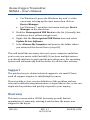
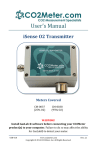
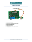
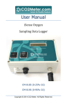
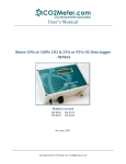
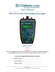
1
User’s Manual Oxygen Transmitter Meters Covered ESCM-37 (25% O2) ESCM-38 (95% O2) WARNING! Install GasLab ® software before connecting your CO2Meter product(s) to your computer. Failure to do so may affect the ability for GasLab® to detect your meter. USR-010 Rev. 2.1 iSense Oxygen Transmitter, NEMA4 – User’s Manual Save meter information for future reference Serial Number: Purchase Date: WARNING! Install this software before connecting your CO2Meter product(s) to your computer. Failure to do so may affect the ability for GasLab® to detect your meter. If this happens, please follow the instructions shown in the “USB Driver Installation Instructions” section on page 20 of this manual. USR-010 REV. 2.1 10/23/2014 PAGE 2 of 23 iSense Oxygen Transmitter, NEMA4 – User’s Manual Table of Contents WELCOME ......................................................................................................................4 IMPORTANT SAFEGUARDS .....................................................................................5 PACKAGE CONTENTS .................................................................................................6 GASLAB® SOFTWARE ...............................................................................................7 MINIMUM SYSTEM REQUIREMENTS ...................................................................................... 7 POWERING THE METER ...........................................................................................9 PRODUCT OVERVIEW ...............................................................................................9 COMPONENT DESCRIPTION .................................................................................................. 11 TERMINAL CONNECTORS ...................................................................................................... 12 LCD DISPLAY.......................................................................................................................... 13 THEORY OF OPERATION........................................................................................................ 14 OPERATION GUIDE ................................................................................................. 14 CONNECTING METERS........................................................................................................... 15 ENTERING THE SERVICE MENU ........................................................................................... 16 STANDARD OPERATION ........................................................................................................ 16 CALIBRATION ........................................................................................................... 16 CALIBRATION USING MODBUS OR PC CONNECTION ..................................................... 17 ATMOSPHERIC SPAN CALIBRATION .................................................................................... 18 ZERO POINT 0% OXYGEN CALIBRATION ........................................................................... 18 METER SPECIFICATIONS ....................................................................................... 19 TROUBLESHOOTING GUIDE................................................................................. 20 USB DRIVER INSTALLATION INSTRUCTIONS .................................................................... 20 SUPPORT .................................................................................................................... 21 WARRANTY................................................................................................................ 21 LIABILITY ................................................................................................................... 22 RETURNS .................................................................................................................... 22 CONTACT US .............................................................................................................. 23 USR-010 REV. 2.1 10/23/2014 PAGE 3 of 23 iSense Oxygen Transmitter, NEMA4 – User’s Manual Welcome Thank you for purchasing our meter. Please take some time to read through this manual in order to become familiar with the meter. Also, please pay special attention to the important safeguards shown on the next page. USR-010 REV. 2.1 10/23/2014 PAGE 4 of 23 iSense Oxygen Transmitter, NEMA4 – User’s Manual Important Safeguards To reduce the risk of fire, electrical shock and/or injury to persons, basic safety precautions should always be followed when using electrical appliances, including the following: 1. 2. 3. 4. 5. READ ALL INSTRUCTIONS BEFORE USING THIS METER. INSTALL GasLab® SOFTWARE BEFORE CONNECTING METER TO A COMPUTER. Use only the included power supply to operate this meter. Do not operate this meter if the enclosure is opened. Do not operate the device if it is malfunctioning. SAVE THESE INSTRUCTIONS! USR-010 REV. 2.1 10/23/2014 PAGE 5 of 23 iSense Oxygen Transmitter, NEMA4 – User’s Manual Package Contents Please verify that your package contains the following items before using the meter: All units include: • • • • • (1) Meter (1) International power supply (1) 2-meter USB to RS-485 cable (1) Certificate of Calibration (1) User manual Figure 1: NEMA4 Data Logger with accessories USR-010 REV. 2.1 10/23/2014 PAGE 6 of 23 iSense Oxygen Transmitter, NEMA4 – User’s Manual GasLab® Software IMPORTANT: MAKE SURE TO INSTALL SOFTWARE BEFORE CONNECTING YOUR METER TO YOUR COMPUTER Minimum System Requirements To utilize our free software, the computer must meet the following minimum requirements: 1GHz processor with 1GB RAM, 1GB free disk space (2GB free disk space for 64-bit systems). Windows XP*/7/8/8.1 with Microsoft .NET Framework 4.0** or later. On Intel-based Mac computers, GasLab® software can run using a Windows 7/8 virtual machine software such as VMware Fusion® or similar. *Microsoft .NET is not supported on Media Center or Tablet editions. **Installer will optionally install .NET Framework. Visit www.co2meter.com/pages/downloadsto download our complimentary GasLab® software to your computer. You can also download the GasLab®’s user manual in PDF from this page. Please read the GasLab®’s user manual carefully to become more familiar with how the software works so that you can get the maximum benefit from this useful tool. Install the GasLab® software first to ensure that the proper driver, necessary for the meter, is installed on your computer before connecting the meter. USR-010 REV. 2.1 10/23/2014 PAGE 7 of 23 iSense Oxygen Transmitter, NEMA4 – User’s Manual Figure 2: GasLab® download page (Internet Explorer 11 shown) Follow the on-line prompts to complete the installation process. NOTE: We strongly recommend allowing GasLab® to install drivers for the meter automatically. Software Capabilities Our GasLab® software will allow users to: • • • • USR-010 Manage and download logs Configure Sensor Adjust logging intervals Calibrate the meter REV. 2.1 10/23/2014 PAGE 8 of 23 iSense Oxygen Transmitter, NEMA4 – User’s Manual • • • Automatic data logging when meter is powered ON Data logging session status displayed on LCD screen Collect data real-time Powering the Meter This meter can be powered by hardwiring 24 VDC power through the MDCM-4FP-2M Cable (included) but sampling units can also be powered by the included 24VDC international wall power supply. Product Overview The oxygen transmitter is a long life oxygen level transmitter that provides multiple analog linear outputs of O2 concentrations. It is designed to be rugged, maintenance-free and can be calibrated in normal air of any known oxygen concentration. Multiple units may be daisy chained for via RS485. Scientific devices such as this level controller require the user to have an intimate knowledge of the meter, its operation, the required software, and the meter specifications prior to use. Edaphic Scientific highly recommends reading this user’s manual before operating the device, especially the Important Safeguards section on page 5. These meters store collected data to their internal memory to be retrieved at a later time for analysis. When combined with our GasLab® software, you can also see real-time data on your computer’s screen. USR-010 REV. 2.1 10/23/2014 PAGE 9 of 23 iSense Oxygen Transmitter, NEMA4 – User’s Manual The table below shows the different level controller models and their typical applications. Model # ESCM-37 ESCM-38 O2 Level 0 - 25% 0 - 100% Sensor Connector PBC Push Buttons LCD Display Dome Cable Gland Terminal Block ¾ NPTF Fitting LED’s Indicate status (S), error (E), and power (P) Figure 3: Instrument Overview USR-010 REV. 2.1 10/23/2014 PAGE 10 of 23 iSense Oxygen Transmitter, NEMA4 – User’s Manual Component Description Display – Main interface to view current sensor readings and menu state. Will blink “STRT” upon applying power while the sensor warms up and stabilizes. LED’s – are in for lower right corner of the unit on the main PCB and are labeled S, E and P. a. “S” LED – Status LED. Blinks every time a complete measurement cycle is performed and the value is updated. Serve’s as a heartbeat for transmitter operation. b. “E” LED – Error LED. Will light if any abnormal conditions are detected within the device, primarily the sensor falling out of its recommended operating specifications will trigger this lamp. c. “P” LED – Power LED. Will be on continuously when power is applied to the unit. PBC Buttons - The unit has three surface mount buttons above the LEDs on the PCB. They can be gently and carefully pressed with your finger. These buttons allow you to access all aspects of sensors operation and test or calibrate different functional modules. Terminal Block – Allows power and output hard wiring. Sensor Connector – Allows simple interfacing between sensor and board. Dome Cable Gland – Industrial liquid-tight strain-relieved gland allows cable(s) routing to hardwire on terminal block. USR-010 REV. 2.1 10/23/2014 PAGE 11 of 23 iSense Oxygen Transmitter, NEMA4 – User’s Manual Terminal Connectors Figure 4 below shows a labeled representation of the terminal block on the board inside these meters. Figure 4: Labeled terminal block (connections) VDC = G- G+ O2 4-20mA = SIG GND RS-485 INTERFACE = A B GND RESET = RST USR-010 REV. 2.1 10/23/2014 PAGE 12 of 23 iSense Oxygen Transmitter, NEMA4 – User’s Manual MODBUS/RS-485 The internal oxygen sensor supports MODBUS protocols over RS485, unidirectional transmission at 9600kbps. The following MODBUS registers are available: Input Registers 1. O2 Value, x10 2. Raw ADC Value Holding Registers 1. 2. 3. 4. 5. 6. 7. 8. O2 Span Value (4 byte floating number, part 1) O2 Span Value (4 byte floating number, part 2) O2 Pot Value 4-20mA output Zero Value 4-20mA output Span Value (4 byte floating number, part 1) 4-20mA output Span Value (4 byte floating number, part 2) Control Register Status Register The following commands are available: 0x03 – Read Holding Register 0x04 – Read Input Register 0x06 – Write Holding Register LCD Display The Liquid Crystal Display (LCD) touchscreen shows the following features: USR-010 Gas concentration level in parts-per-million (ppm) or in percentage format (##.##%) for all the models REV. 2.1 10/23/2014 PAGE 13 of 23 iSense Oxygen Transmitter, NEMA4 – User’s Manual Theory of Operation The zirconia oxygen sensor utilizes solid-state electrochemical reactions to produce a voltage proportional to the current oxygen. This voltage is then digitalized and filtered to a usable value. The oxygen sensor has also been factory calibrated to meet specifications. Operation Guide Make sure you read through these instructions thoroughly before using the meter. This guide will help you become more familiar with the meter in order to be as productive as possible in a short period of time. Please read the Important Safeguards on page 5 before continuing. IMPORTANT: Follow these instructions to ensure proper set up: 1. Start by downloading the GasLab® Software to your computer as shown in the Figure 2 on page 8. 2. Power the meter. NOTE: connecting the included USB cable to a port in a computer will not supply the appropriate power. 3. Turn ON the meter. USR-010 REV. 2.1 10/23/2014 PAGE 14 of 23 iSense Oxygen Transmitter, NEMA4 – User’s Manual Connecting Meters The first time the meter is connected to your computer, the operating system will install the necessary USB drivers as shown in Figure 5. This process could take a few minutes. Figure 5: USB Driver Installation. Figure 6: Collecting data in real time USR-010 REV. 2.1 10/23/2014 PAGE 15 of 23 iSense Oxygen Transmitter, NEMA4 – User’s Manual Entering the Service Menu To enter the service menu the buttons must be pressed in a factoryset order. This code can be customized before shipment but by default will be 1-2-3. The buttons must be pressed within a half second of each other, else the unit will return to standard operating mode. When in the service menu the unit will not update the current O2 readings. Once you enter the menu the display will read “1225 or 1295”. Standard Operation The O2 transmitters comes factory calibrated for easy installation. During its life cycle calibration may become periodically necessary. We recommend performing a span O2 calibration every month for guaranteed operation and ensured accuracy. Calibration is recommended every six months. Calibration The calibration process varies depending on the type of unit and whether it has optional data logging functionality or not. All units are factory-calibrated with multiple reference points of gas, and have been verified to be accurate within their specific functionality before shipment. However, if the unit is severely jolted or otherwise mechanically disturbed, the sensor can drift requiring recalibration. All calibration procedures follow a single-point calibration routine that effectively shifts the zero-point of the O2 sensor. USR-010 REV. 2.1 10/23/2014 PAGE 16 of 23 iSense Oxygen Transmitter, NEMA4 – User’s Manual Calibration using MODBUS or PC Connection You can Download the software directly and free from this link in our website. More precise calibrations can be performed using the PC connection. The unit can be attached to a PC using an optional USB to RS-485 cable, available on our website, or via a mini-USB cable to the internal USB connection. In the desktop software application O2 can be calibrated individually. The O2 sensor can be calibrated to 0% and then to 20.9%. During normal operation 0% calibration of the oxygen transmitter should not be necessary. Calibration can also be performed over MODBUS, see additional documentation for MODBUS registers. Calibration can be performed using either 0% CO2 calibration gas (typically nitrogen, Argon, etc.), or using a fresh source of air, assumed to be approximately 20.9% O2. Attach calibration gas to the unit and connect the unit to a personal computer. Open the calibration screen in the GasLab software. Click the “Calibrate” button in the calibration tab for the desired gas, located in the “Configure Sensor” screen. As long as the gas concentration is stable, the unit should instantly reflect the calibrated value. This can be confirmed by watching the display. USR-010 REV. 2.1 10/23/2014 PAGE 17 of 23 iSense Oxygen Transmitter, NEMA4 – User’s Manual Figure 7: Data logger calibration screen for 0-1% CO2 Atmospheric Span Calibration 1. 2. 3. 4. 5. Allow sensor to stabilize for at least 1 hour Ensure the sensor is exposed to fresh air Enter the service menu Press 2 to enter the Oxygen submenu Press 2 again to perform the atmospheric calibration Zero Point 0% Oxygen Calibration 1. 2. 3. 4. 5. 6. 7. Allow sensor to stabilize for at least 1 hour Screw on the calibration adapter Apply N2 calibration gas Wait 5 minutes for stable readings Enter the service menu Press 2 to enter the Oxygen submenu Press 1 to calibrate USR-010 REV. 2.1 10/23/2014 PAGE 18 of 23 iSense Oxygen Transmitter, NEMA4 – User’s Manual Meter Specifications Measuring Principle Measuring Range Accuracy O2 Sensor Performance and Ratings Repeatability Sensitivity Warm-up Time Outputs Power Dimensions USR-010 Response Time Life Expectancy Maintenance Interval Voltage O2 Value RS-485 Input Voltage Current Consumption WxHxD in(mm) Zirconium dioxide (ZrO2) 0-25% (25% O2) 0-95% (95% O2) ±2% full scale (all ranges) ±0.05% or ±0.02% for 25% or 95% O2, respectively, ±1% of measured value ±20 ppm ±1% of measured value <15 min. (instant measurements) 4 sec. max. diffusion >15 years No maintenance required 0 – 10 VDC 4-20 mA linearly scaled Modbus interface 24 VDC ±10% 600 mA @ 24 VDC 4.7(120) x 3.2(80) x 3.2(81) REV. 2.1 10/23/2014 PAGE 19 of 23 iSense Oxygen Transmitter, NEMA4 – User’s Manual Troubleshooting Guide Symptom / Issue Possible Cause / Resolution Device is not recognized by PC/OS Device doesn’t power ON The GasLab® software doesn’t start *1 Make sure meter is connected properly to a suitable 24VDC power supply and that the USB cable is properly connected to a computer. Perform resolution above and make sure that there is adequate power to the meter. Your software might be out of date. Update your software by either visiting our download webpage at http://www.co2meter.com/pages/downloads or by selecting the “Check for Updates” under the Help menu. Make sure your PC meets the minimum requirements. Calibration or recalibration needed. Reading doesn’t change *For more troubleshooting tips on GASLAB® software, see GASLAB® manual located at www.co2meter.com/pages/downloads. USB Driver Installation Instructions To install the appropriate USB port drivers compatible with your meter, follow these steps: 1. Go to http://www.ftdichip.com/Drivers/VCP.htm and download the package appropriate for the version of Windows installed in your computer. 2. Move the file you downloaded to a location you can easily access. Make sure you have administrator privileges. 3. Extract the file by right clicking on it and selecting extract here. 4. Go to your computer’s Device Manager in the Control Panel. USR-010 REV. 2.1 10/23/2014 PAGE 20 of 23 iSense Oxygen Transmitter, NEMA4 – User’s Manual For Windows 8, press the Windows key and 'x' at the same time to bring up the start menu then click on Device Manager. For Windows 7, open the start menu and type Device Manager in the search bar. 5. Find the Unrecognized USB Device in the list (it usually, but not always, has a yellow triangle icon). 6. Right click the Unrecognized USB Device item and select Update Driver Software. 7. Select Browse My Computer and point to the folder where you extracted the driver files to (step #3). This will install the necessary drivers to your computer and allow you to use your meter with GasLab®. If you have multiple meters, you should only have to perform this procedure once; the operating system will automatically find the driver for all the other sensors. Support The quickest way to obtain technical support is via email. Please send all support inquires to [email protected] Please include a clear, concise definition of the problem and any relevant troubleshooting information or steps taken so far, so we can duplicate the problem and quickly respond to your inquiry. Warranty This meter comes with a 1YEAR (warranty period) limited manufacturer’s warranty, starting from the date the meter was shipped to the buyer. USR-010 REV. 2.1 10/23/2014 PAGE 21 of 23 iSense Oxygen Transmitter, NEMA4 – User’s Manual During this period of time, Edaphic Scientific warrants our products to be free from defects in materials and workmanship when used for their intended purpose and agrees to fix or replace (at our discretion) any part or product that fails under normal use. To take advantage of this warranty, the product must be returned to Edaphic Scientific at your expense. If, after examination, we determine the product is defective, we will repair or replace it at no additional cost to you. This warranty does not cover any products that have been subjected to misuse, neglect, accident, modifications or repairs by you or by a third party. No employee or reseller of Edaphic Scientific’s products may alter this warranty verbally or in writing. Liability All liabilities under this agreement shall be limited to the actual cost of the product paid to Edaphic Scientific. In no event shall Edaphic Scientific be liable for any incidental or consequential damages, lost profits, loss of time, lost sales or loss or damage to data, injury to person or personal property or any other indirect damages as the result of use of our products. Returns If the product fails under normal use during the warranty period, a RMA (Return Material Authorization) number must be obtained from Edaphic Scientific. After the item is received Edaphic Scientific will repair or replace the item at our discretion. USR-010 REV. 2.1 10/23/2014 PAGE 22 of 23 iSense Oxygen Transmitter, NEMA4 – User’s Manual CO2Meter.com To obtain a RMA number, email us at [email protected] When requesting a RMA please provide reason for return and original order number. If the product fails under normal use in the first 10 days of ownership, at our discretion we will email you a postage-paid UPS label to return the product at our expense. If we determine that the product failed because of improper use (water damage, dropping, tampering, electrical damage etc.), or if it is beyond the warranty date, we will inform you of the cost to fix or replace the product. Contact Us We are here to help! For information or technical support, please contact us. [email protected] www.edaphic.com.au Address: PO Box 1843 Port Macquarie, NSW, 2444, Australia USR-010 REV. 2.1 10/23/2014 PAGE 23 of 23