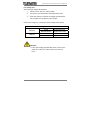
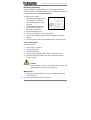
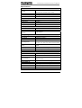
1
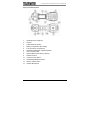
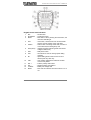
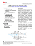
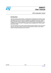
TECHNICIANS TEST PHONE
User’s Manual
IP54
1st Edition
© 2010 Access Communications Pty Ltd
Technicians Test Phone User’s Manual
Thank you for purchasing a Telemaster® Test Telephone. Before using it
for the first time, please read the following instructions.
Warning:
The Telemaster® Test Telephone is designed for checking
analog telecommunications lines and must not be connected to
240V mains power circuits as there will be possible electric
shock or product damage. If you are uncertain of the voltage
on the circuit you want to test, first set the test set to VDC
mode and verify that the voltage is within a safe working range.
Features
1.
Complies with IP54 Dustproof & Waterproof tests
2.
Drop Protection
3.
Australian A-Tick compliance approval
4.
High impedance monitoring
5.
Circuit voltage-range LED indicators
6.
Line Continuity test
7.
Continuous polarity LED indicators
8.
Speakerphone for convenient hands-free two-way conversation
9.
Tone or pulse operation
10. Store up to twelve 16-digit speed-dial numbers plus an additional
number store in the M1 button
11. Last number redial
12. PBX pause button
13. Mute switch
14. Electronic switch controls the volume of the speakerphone/monitor.
15. Automatic shut-off feature turns off speaker after five minutes of
inactivity
16. Battery low-voltage LED indictors
17. Audible electronic ringer
18. Relocatable steel locking belt clip
19. Test clips and a 6P6C Modular plug are provided
www.accesscomms.com.au
1
Technicians Test Phone User’s Manual
Physical Characteristics
1.
Speakerphone microphone
2.
Keypad
3.
Talk/Vdc/Monitor Switch
4.
Battery Compartment (9V battery)
5.
Fuse (in battery compartment)
6.
Speakerphone/Monitor amplified speaker
7.
Line cord strain relief
8.
Optional Belt Hook location (2 places)
9.
Handset receiver
10.
Increase volume button
11.
Handset/Speakerphone button
12.
Reduce volume button
13.
Handset Microphone
2
www.accesscomms.com.au
Technicians Test Phone User’s Manual
Keypad control and indicators:
1.
2.
3.
RCL
PPS/DTMF
MUTE
4.
VDC
5.
CABLE
6.
VDC(HI/LO)
7.
8.
PSE
STO
9.
M1
10.
LNR
11.
12.
13.
14.
POL +
POL LO BATT
MUTE
: Recall button.
: Tone/Pulse switch.
: Mute button. When pressing the mute button, the
red mute LED will light
: VDC button, check if the line is connected well
and test, test the voltage of the outer-lead
: Telecom line connecting-check LED, if the line is
connected well, the LED lights up red
: Voltage level LED indicator (please see the DC
voltage-indication list)
: PBX pause button
: Store button is used for storing speed dialing
numbers
: Speed dialing button when the test set is on
without press any other key
: Last number redial button redials the number
most recently dialed
: Positive polarity LED indictor
: Negative polarity LED indictor
: Battery low-voltage LED
: Mute LED to indicate if the mute function is on or
not
www.accesscomms.com.au
3
Technicians Test Phone User’s Manual
Operation
Talk/VDC/Monitor switch
The test set has three basic modes of operation: Talk mode, off mode
and Monitor mode.
The T (talk) position gives an off hook condition for dialing and talking
like a common analog telephone.
The VDC position checks the voltage level of an incoming ring.
The M (monitor) position removes the transmitter from the circuit and
provides a high impedance coupling to allow line monitoring without
disrupting conversations or signaling.
There is no complete power off mode. The major function of
"VDC" mode is for AC/DC power testing. The Mute LED will light up if
the mute button is touched in the VDc mode and the battery will supply
power to operate the LED until it is drained. Please make sure the
Mute button is off before storing the unit to avoid unnecessary
battery drain.
Speaker and Speakerphone Microphone
The speaker and speakerphone microphone are located on the keypad
side of the test set. The speaker draws more current than any other
circuit in the test set and the battery lasts longer if the speaker is used in
moderation.
Audio Controls Keys
The control keys (VOL + / SPKR/
VOL -) are located on the inside
handle of the test set between
the handset receiver and the handset microphone. These controls let
you switch between the handset and speakerphone. The SPKR button
turns the test set speaker on and off. When the SPKR turns on the
Speakerphone, this mode is intended for two-way, hands-free
conversation. The VOL+ and VOL- keys control the active receiver’s
sound level.
4
www.accesscomms.com.au
Technicians Test Phone User’s Manual
Tone/Pulse button
The PPS/DTMF button works as a Tone/Pulse switch. Pressing this
button toggles between Pulse and Tone modes.
Storing Speed-Dial Numbers
The STO button is used to store numbers in memory. There are 12
memory locations (keys 0 through 9, * and #), with each capable of
storing up to 16 digits.
To store a number:
1. Set the function button to “T” position.
2. Dial the number to be stored
3. Press STO button
4. Press the key for the desired memory location.
Dialing using Recall key
The RCL key is used to recall a number stored in memory. To dial the
stored number
1.
Set the function button to “T” position
2.
After receiving dial-tone, press RCL button
3.
Press the key for the memory location (keys 0 through 9, *and #)
Dialing using the M1l key
The M1 key stores one number using the same process above. If the
function button is in the “T” position and M1 button is pressed, the
stored number will be automatically dialed.
Last Number Redial
The LNR key redials the number most recently dialed.
Pause
There are some cases where it may be necessary to insert a pause
between digits of a stored number, such as when accessing a trunk
through a PBX that requires a digit 9 to access an exchange line. To
store a number with a pause, simply press the PSE button at the point
where the pause is required. The PSE button inserts a 4 second pause.
www.accesscomms.com.au
5
Technicians Test Phone User’s Manual
Operating the Test Set in Monitor Mode
Set the function switch to “M” position and then press the SPKR button
to open the monitor function.
During monitoring please
ensure the Line Continuity
Test is not used to prevent
crosstalk and low volume sound. To control the volume level, press
VOL+ to increase volume and press VOL- for reduced volume.
Mute function
The mute button turns the handset microphone and speakerphone
microphone off for privacy in Talk mode.
Polarity Identification
The polarity LEDs automatically illuminate to show line polarity. For
example, the right red POL+ LED will light when you connect the red
test lead to ring (positive) side of the line and the black test lead is
connected to the tip (negative) side of the line. The left red POL- LED
will light if the test leads are reversed.
Line Continuity Test
If you want to check that the line is correctly connected:
1.
Connect the two sides of the telecom line to the test phone
2.
Set the function switch to “VDC” position.
3.
Press the VDC button.
If the CABLE LED lights, it means the line is OK. If the CABLE LED
does not light that means the line is not OK.
Battery
If the LO BATT LED lights, you need to change the battery to prevent
data loss. To extend battery life, the speaker will automatically
shut off after approximately five minutes if there has not been a
signal greater than -30 dB in that period. Any signal greater than
-30 dB resets the timer and keeps the speaker turned on
6
www.accesscomms.com.au
Technicians Test Phone User’s Manual
Line voltage test
Outer-lead high voltage LED indication
1.
Set the function switch to “VDC” position.
2.
Connect the two outer-leads to the angled bed of nails.
3.
Press VDC button to measure the voltage and indicate the
LO/HI voltage level by different color of lights.
If both LED not lights up, it means the tested voltage under DC24V.
DC voltage-indication list
LED(LO)
LED(HI)
Green
Higher than 24V
Red and Green
Higher than 100V
Green
Higher than 150V
Red and Green
Higher than 200V
Caution:
1. If the circuit voltage is greater than 250V or the function
switch is not set to the “VDC” position; the fuse may
blow. .
www.accesscomms.com.au
7
Technicians Test Phone User’s Manual
Trouble Shooting
Defect Situation
Possible Problem
Solution
Dead, Doesn’t work
Blown fuse
No tone
Angled bed of nails are not
well connected
Speakerphone
doesn’t work
Short rings only
Change fuse
MUTE button was pressed
and MUTE LED indicator
lights up
1. Low battery
2. the angled bed of nails
are connected to the
power source
Can not hear the
conversations on the
Monitor status
1. The switch is not set to
“M” position
2. The SPKR button is off
3. Low battery
Crosstalk
1. Angled bed of nails are
not connected firmly
2. Interference from the
line
Memory of storing
numbers doesn’t
work
Polarity LED
doesn’t work
CABLE LED
doesn’t work
LO HI(LED)
doesn’t work
BATT(LED)
doesn’t work
8
Check if Angled bed of
nails are well connected to
telecom line
Press the MUTE button
and check if the MUTE
LED is off
1. Change battery
2. Confirm if the angled
bed of nails connected
to the right telecom line
1. Set the switch to “M”
position
2. Press the VOL+ button
to increase volume
3. Change battery
1. Check if the Angled
bed of nails are well
connected
2. Press the VOL-button
to
reduce
the
interference
Low battery
Change battery
Low battery
Change battery
Low battery
Change battery
Low battery
Change battery
Low battery
Change battery
www.accesscomms.com.au
Technicians Test Phone User’s Manual
Replacing the Battery
If the test set fails to operate properly, or stops working, replace the
battery and retest. A 9V alkaline battery must be installed for the test set
to operate. Do not us rechargeable batteries.
To replace the 9V battery:
1. Disconnect the test set from the
line and place on a flat work
surface with the battery cover
facing up.
2. Use a Phillips screwdriver to
remove the four screws from
the battery compartment.
3. Remove the battery cover
4. Remove the old battery and properly discard.
5. Insert a new 9V battery into the test set and observe the proper
polarity.
6. Place the battery cover back and fasten the four screws securely.
Fuse replacement
To replace the fuse:
1.
Follow steps 1 to 3 above
2.
Remove the battery
3.
Remove the old fuse
4. Insert a same specification (ø5xL20mm, 250mA/250V) fuse
5. Place the battery and battery cover back, then fasten the four
screws securely.
Caution
After the battery is removed, the stored number memory will
retain stored information for 10 seconds only.
Maintenance
1. Disconnect the test telephone from any circuit before performing
any maintenance.
2. Do not use chlorinated solvents on the test set
www.accesscomms.com.au
9
Technicians Test Phone User’s Manual
Specifications
ELECTRICAL
Loop limit
2 KΩ maximum at 48 VDCdc
(nominal 20mA minimum loop current)
DC resistance
Talk Mode
300Ω typical
Monitor impedance
39kΩ nominal at 1 KHz
Rotary dial output
Pulsing rate
10pps+0.8pps
Percent break
61%±2%
Interdigit interval
1000 ms typical
Leakage during Break
>50 KΩ
DTMF output
Tone frequency error
±1.2% maximum
Tone level
-8±2dBm combined (typical)
High versus low tone
Difference
4 dB maximum
Memory dialing
Memory capacity
13 memories including M1, last number redialing
Digit capacity
16 digits per memory
PBX pause duration
Line Voltage Test
Monitor amplifier power
4 seconds
5 Phase AC/DC voltage indication(under24 V、
24~100V、101~150V、151~200V、more than 200V)
9V transistor; provides 25 hours continuous use,
source
typical
Automatic power shut off
After 5 min. of no audio signal
Speaker phone levels
Electronic adjustable
Power source
battery (9V) 6F22 (not included)
PHYSICAL
Measurement
Weight
Water Resistance
Cord Sets
230 ×82 × 89mm (9-1/16” × 3-15/64” × 3-1/2”)
635g typical
Complied with IEC/EN 60529 IP54 Dustproof &
Waterproof tests
Angled bed of nails and RJ11 plug
ENVIRONMENTAL
Temperature
Operating:0 to 50°C / Storage:-10 to 60°C
Altitude
To 10,000 feet (3,000M) max
Relative humidity
5 To 95%
CERTIFICATE
IP54, CE approved
10
www.accesscomms.com.au
Technicians Test Phone User’s Manual
www.accesscomms.com.au
11