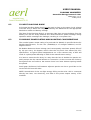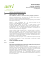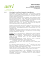
1
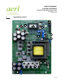
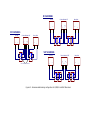
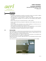
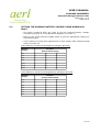
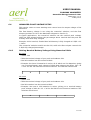
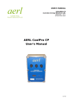
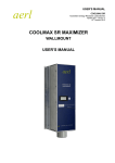
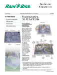
USER'S MANUAL
COOLMAX MAXIMIZER
Australian Energy Research Labs
AER01.003 – ver 3
24 May 2010
AERL CoolMax Maximizer
User's Manual
1 of 20
USER'S MANUAL
COOLMAX MAXIMIZER
Australian Energy Research Labs
AER01.003 – ver 3
24 May 2010
TABLE OF CONTENTS
1
Overview.........................................................................................................3
2
Maximizer Layout............................................................................................4
3
Safety Precautions..........................................................................................6
4
Circuit Breakers...............................................................................................6
5
Installation......................................................................................................8
5.1
5.2
5.3
5.4
5.5
5.5.1
5.5.2
5.6
5.7
5.8
5.9
Mounting............................................................................................................... 8
Earthing................................................................................................................. 8
Connections........................................................................................................... 8
Setting the Nominal Battery Voltage Using Numerical Dials..................................9
Advanced Float Voltage Setup.............................................................................10
Setting Nominal Battery Voltage Using Numerical Dials......................................10
Adjusting the Float Trimpot..................................................................................11
Battery Charging Setup.......................................................................................11
Temperature Compensation.................................................................................11
Low Battery Detection and Relay Alarm...............................................................12
Remote Control.................................................................................................... 12
6
Operating Guidelines.....................................................................................13
6.1
6.2
Configuring the Unit............................................................................................ 13
Using the Onboard LCD Meter Module.................................................................13
7
PV ARRAY CONFIGURATION NOTES.................................................................13
7.1
7.2
7.3
Optimal PV Array Configuration...........................................................................13
PV Input Blocking Diode.......................................................................................14
PV Module Power Rating and Mounting Considerations.......................................14
8
Special Application Guidelines.......................................................................14
8.1
8.2
8.2.1
8.2.2
8.2.3
Water Pumping Applications................................................................................14
Micro-Turbine Maximizers.....................................................................................15
Selecting the Load Dump Regulation Power Resistor ..........................................15
Low Battery Circuitry on u-Turbine Units..............................................................16
Setting the Turbine Operating Set Point Voltage..................................................16
9
Troubleshooting............................................................................................17
9.1
9.2
9.3
9.4
Low Battery Light Often Comes On......................................................................17
Unit Does Not Charge the Battery........................................................................17
Battery Bank Using Excessive Water (Electrolyte)...............................................18
Blown Fuse.......................................................................................................... 18
10
Warranty Information....................................................................................19
2 of 20
USER'S MANUAL
COOLMAX MAXIMIZER
Australian Energy Research Labs
AER01.003 – ver 3
24 May 2010
1
OVERVIEW
The AERL Coolmax Maximizer is a high efficiency, buck only, common positive
peak power point tracker.
It employs a tracking strategy which has been proven to be highly robust,
immune to local extrema, and results in power losses of less than 0.5% over the
whole operating temperature range of a PV Array.
The versatility of the Coolmax Maximizer makes it an ideal choice for battery
charging, pumping, DC motors and other solar powered applications.
The Maximizer range can also be used for Micro-Turbine (uTurbine) applications
including hydro and wind using a fixed turbine voltage set point to approximate
the peak power voltage.
Additional features include:
• High 98 – 99% operating efficiency.
• Smart multi-stage battery charging profile.
• Support for active temperature compensation.
• Compatible with all types of solar cells and battery arrays.
• Onboard meter module for performance monitoring.
• Passive cooling & no moving parts results in highly reliable operation to 50°C .
• Rugged protective enclosure with easy access door. (optional)
• Support for low battery alarm or automatic low battery switch off circuit.
Note: For convenience, this user's manual is oriented towards solar Maximizers
being used to supply a battery pack. For those supplying a DC pump, or using the
uTurbine version of the Maximizer, the majority of the information is still relevant
and it is still recommended to become familiar with the contents of the manual.
Section 9 details the critical information specific to operating the Maximizer with a
DC pump or using the uTurbine version of the Maximizer.
3 of 20
USER'S MANUAL
COOLMAX MAXIMIZER
Australian Energy Research Labs
AER01.003 – ver 3
24 May 2010
2
MAXIMIZER LAYOUT
9
2
3
4
7
1
6
5
10
8
11
12
13
14
4 of 20
USER'S MANUAL
COOLMAX MAXIMIZER
Australian Energy Research Labs
AER01.003 – ver 3
24 May 2010
Position
Name
1
LED status
indicators
Function
Low battery light activates at 10.5V/12V battery voltage.
100% full light activates when batteries have finished auto
equalize.
2
On/Off switch
Switches Maximizer on/off.
3
Meter range
toggle (HV
only)
Choose between high and low range output for meter module.
4
LCD meter
module
Displays input voltage, output voltage, output current, battery
current.
5
Battery 100%
Float
adjustment
trimpot
Adjusts battery 100% float level
6
Battery
nominal
voltage dials
Used for setting the nominal battery pack voltage. Can be
used for speed control in pump/motor applications.
7
Metering mode
switch
Choose between metering input voltage, output voltage,
output current, battery current.
8
Piano dipswitch
1. Set up the Maximizer for sealed batteries, different types of
solar arrays.
2. Turn Temperature Compensation on or off.
3. Control whether the Maximizer is “On by default” or “Off by
default” for remote control.
9
Low battery
alarm
/
Provides normally closed and normally open outputs which
are activated when low battery LED comes on. This can be
used for a remote alarm system or for genset control to
charge the batteries.
Genset control
10
Temp comp
sensor header
Attach PTC thermistor to battery pack with wires into the
header.
11
Remote control
header
Terminals of header can be linked for remotely controlling the
Maximizer. Can be used as input from a sensor such as float
switch in pumping applications.
12
Battery fuse
Protection against reverse connection of the batteries &
overcurrent situations.
13
PV input
terminal
14
Battery/pump/
DC motor
output terminal
Input from solar array.
Output to batteries/pump/motor.
5 of 20
USER'S MANUAL
COOLMAX MAXIMIZER
Australian Energy Research Labs
AER01.003 – ver 3
24 May 2010
3
SAFETY PRECAUTIONS
WARNING:
OPERATE,
ADEQUATE
QUALIFIED
TO.
THE DC VOLTAGE LEVELS AT WHICH THE MAXIMIZER CAN
CAN BE POTENTIALLY LETHAL IF HANDLED WITHOUT
CAUTION. INSTALLATION MUST BE CARRIED OUT ONLY BY A
ELECTRICIAN AND ALL APPLICABLE SAFETY CODES ADHERED
DO NOT EXCEED THE CURRENT AND VOLTAGE RATINGS LISTED IN THE
DATASHEET. TO DO SO, IMMEDIATELY VOIDS THE WARRANTY.
• In particular the PV Input Open-Circuit Voltage and Power rating must not be
exceeded.
• Note: The power rating of the Maximizer varies depending on Vnom
(nominal battery voltage) and Vmp (peak power voltage of solar
panels – available from panel datasheet). Check the charts in the
datasheet to find an approximate power rating at your desired
operating point. Not being aware of the power rating at your
operating point can lead to premature failure.
• Always ensure that the Maximizer On/Off switch is set to off and the Maximizer
Off switch on the Piano switch is depressed before making or breaking any
connections.
• Never touch the Maximizer while the input OR output breakers are closed. This
includes when the Maximizer is switched off on the PCB. Switching off the
Maximizer does not isolate the Maximizer, and any part of the circuitry may
have lethal voltages present.
• Always measure the PV Open-Circuit Voltage and Polarity and Battery Polarity
before closing the circuit-breakers and making the final connection to the
Maximizer.
4
CIRCUIT BREAKERS
ALWAYS FIT DC RATED INPUT AND OUTPUT PROTECTION CIRCUIT BREAKERS – DO
NOT USE FUSES
Always select at least 6kA rated breakers, as these have a better DC arc
quenching capability than the only slightly less expensive and more common 4kA
breakers. If available, 8kA or 10kA breakers are the very best choice for DC
systems.
AERL recommends the use of Siemans or similar brand 6kA MCBs as an
inexpensive breaking solution. (Example: Siemans Part No. 5SJ62206KS). Refer to
figure 4.1 on the following page to determine the appropriate breaker types and
wiring configuration for LV, MV, HV and XHV Maximizers. For XXHV units, a high
voltage DC breaker will be needed.
6 of 20
HV MAXIMIZERS
Battery Bank
OUT
+ +
|
|
IN
|
+
Coolmax Maximizer HV
|
PV Array
+
MV MAXIMIZERS
Battery Bank
OUT
+ +
|
|
IN
+
XHV MAXIMIZERS
IN
Battery Bank
OUT
+ +
Figure 4.1: Recommended breaking configuration for LV,MV,HV and XHV Maximizers.
|
+
|
Siemans 6kA 20A Triple Pole MCB
Coolmax Maximizer XHV
|
PV Array
|
|
+
Coolmax Maximizer MV
|
PV Array
+
USER'S MANUAL
COOLMAX MAXIMIZER
Australian Energy Research Labs
AER01.003 – ver 3
24 May 2010
5
MOUNTING
5.1
LOCATION
• If possible, the Maximizer should be mounted vertically (on a wall or similar)
with the meter at the top to maximize convection cooling.
• If the Maximizer is to be mounted in a cabinet, ensure that the cabinet is large
and adequately ventilated. Do not mount the unit anywhere that airflow is
restricted.
• Never mount the unit in a sealed enclosure, it will overheat.
• Power transfer efficiency through the Maximizer will be better the cooler the
unit is kept.
• Do not mount the unit where rain or direct sunlight can reach the unit, or
where moisture condensation can affect the unit
• The cables should always route down out of the Maximizer so that moisture
condensation on the cables drips away from the electronics.
• The Maximizer should be mounted out of reach of children.
5.2
ENCLOSURE
When supplied in an optional high quality IP66 enclosure, the Coolmax Maximizer
ships with additional mounting brackets with screws for fitting directly to the
bottom of the enclosure using pre threaded holes.
The mounting brackets are simple to install and the bracket can be bolted onto
the mounting surface in a variety of configurations.
Note that the screw should be tightened firmly to avoid having the bracket rotate
during installation.
The enclosure must be provided with protection from rain and direct sunlight.
Figure 5.2: The mounting bracket fastened to the bottom of
the IP66 enclosure.
8 of 20
USER'S MANUAL
COOLMAX MAXIMIZER
Australian Energy Research Labs
AER01.003 – ver 3
24 May 2010
5.3
BARE PCB
Mounting the bare PCB version of the Coolmax Maximizer should be performed
using the supplied M5 bolts and spacers.
If possible, the Maximizer should be bolted onto a flat mounting plate which can
then in turn be mounted in the desired location.
Always keep the minimum space behind the board as set by the spacers to avoid
short circuits caused by materials touching the back of the PCB.
6
INSTALLATION
6.1
EARTHING
• AERL recommends that the Maximizer be utilized in a floating system (no
earthing) whenever possible. For very exposed systems, it is recommended
that a lightning conductor be provided nearby to prevent damage to PV
equipment, batteries and the Maximizer.
• For systems using Sunpower PV arrays, it is necessary to provide a positive
earth for the array. This can be implemented by connecting the Earth Stake
(bottom left corner of the Maximizer) directly to earth.
• If a negative earth is used for the batteries or DC system, do not earth the
array.
• If a negative earth is used for either the batteries or DC system, never earth
the Maximizer via the Earth Stake.
6.2
CONNECTIONS
• Ensure that the Maximizer is switched OFF.
• Use appropriately rated wire to connect PV input and battery bank output.
Polarity is indicated on the board. Reversing polarity of input or output will
cause damage to the Maximizer.
• Install circuit breakers as described in Section 4.
• Check the polarity of the input and output with a multimeter before switching
on the Maximizer.
• Do not touch the Maximizer PCB when live wires are connected to the input or
output terminals – even if the Maximizer is switched OFF, lethal voltages are
still present in the circuitry on the PCB.
9 of 20
USER'S MANUAL
COOLMAX MAXIMIZER
Australian Energy Research Labs
AER01.003 – ver 3
24 May 2010
6.3
SETTING THE NOMINAL BATTERY VOLTAGE USING NUMERICAL
DIALS
• The three numerical dials are used to set the nominal battery voltage.
(Located at position 6 on the Maximizer diagram in Section 2)
• Refer to the quick reference tables below to get the appropriate setting for
your battery pack.
• Users wanting to make fine adjustments to their battery float voltage should
refer to Section 5.5.
Quick Reference Guide for Setting Float Voltages: HV Units
Nominal
Voltage
HV Units
Numerical Dial Setting
48V
0
2
4
72V
0
4
8
96V
0
7
2
108
0
8
4
120V
0
9
6
144V
1
2
0
168V
1
4
4
Quick Reference Guide for Setting Nominal Voltages: MV Units
Nominal
Voltage
MV Units
Numerical Dial Setting
12V
0
0
0
24V
0
1
2
36V
0
2
4
48V
0
3
6
60V
0
4
8
72V
0
6
0
84V
0
7
2
10 of 20
USER'S MANUAL
COOLMAX MAXIMIZER
Australian Energy Research Labs
AER01.003 – ver 3
24 May 2010
6.4
ADVANCED FLOAT VOLTAGE SETUP
This section caters to users wanting more control over the output voltage of the
Maximizer.
The float battery voltage is set using the numerical switches, and the float
trimpot (positions 5 & 6 on the Maximizer diagram in Section 2).
In typical applications, the numerical switches set the nominal pack voltage,
while the float trimpot adjusts the percentage above nominal that the pack will
actually float when fully charged.
Example: A 12V nominal, flooded lead acid battery is fully charged at 2.35/2 x 12
= 14.1V.
The numerical switches would set the 12V, while the float trimpot controls the
2.35/2 fully charged percentage.
6.4.1
Setting Nominal Battery Voltage Using Numerical Dials
HV users
• Offset: 24V
• Take the nominal voltage of your pack and subtract 24V.
• Dial this number into the numerical dials.
• Example: You have 12 batteries in series, all of which are 12V batteries, giving
you a nominal battery pack voltage of 144V. Now subtract the offset. 144 – 24
= 120. So dial 120 into the numerical switches. The switches should read
1
2
0
MV users
• Offset: 12V
• Take the nominal voltage of your pack and subtract 12V.
• Dial this number into the numerical dials.
• Example: You have 4 12V batteries in series, giving you a nominal battery
pack voltage of 48V. 48 – 12 = 36. So dial 36 into the numerical switches. The
switches should read
0
3
6
11 of 20
USER'S MANUAL
COOLMAX MAXIMIZER
Australian Energy Research Labs
AER01.003 – ver 3
24 May 2010
6.4.2
Adjusting the Float Trimpot
Maximizers have the default 100% battery float voltage set to 2.35V/2V before
shipping. This value can be adjusted using the trimpot labelled “Battery 100%
Float” near the piano dipswitch.
NOTE: This float voltage should not be adjusted without good reason. The voltage
can only be adjusted when the Battery 100% LED is ON.
Adjustment Procedure
1. Set the switch next to the built in LCD meter display to battery volts.
2. Adjust the battery float trimpot: clockwise = higher
3. The voltage will move very slowly, so the adjustment should be made patiently
over several minutes.
As a guideline for adjustment, the battery float voltage changes by about 1% of
nominal voltage for one complete turn on the trimpot. So if the nominal voltage
is 48V, one turn of the trimpot will adjust the float voltage by roughly 0.48V.
6.5
BATTERY CHARGING SETUP
• The batteries are charged using a 108% of Final 100% Float Voltage,
Automatic Equalise Voltage / Anti-Sulphation charging profile.
• The default setting for Maximizers is for 2.35V/2V flooded lead acid batteries.
For sealed lead acid batteries also depress the appropriate switch on the piano
dipswitch to set the float level to 2.3V/2V lead acid cell.
• Press down the 3rd Piano Dip Switch marked THIN FILM SILICONE, if the PV
Panels being used are of the Amorphous Thin Film type.
• Press down the Fourth Piano Dip Switch marked SUNPOWER SILICONE, if the
PV Panels being used are the high performance SUNPOWERTM BRAND. (This
setting is also suitable for GaAs Panels).
• IMPORTANT: To avoid overloading the Maximizer, pay attention to the warnings
given in Section 3. As mentioned in Section 3, it is important to avoid
connecting the Maximizer to a PV Array if its power rating exceeds quoted
power rating of the Maximizer for that given battery bank voltage. To do so
will overload the current handling capabilities of the product, most likely cause
damage to the board and void the warranty.
6.6
TEMPERATURE COMPENSATION
• If precise battery case temperature compensation is required, unscrew the
Thermistor from 13 & 14 and solder it to a suitable light 2 core cable and
adhere the thermistor to the battery case with neutral-cure silicone rubber
adhesive. Connect the other ends of the two core cable back into the
thermistor terminal block 13 & 14.
12 of 20
USER'S MANUAL
COOLMAX MAXIMIZER
Australian Energy Research Labs
AER01.003 – ver 3
24 May 2010
• If the Temperature Compensation Feature is not required, simply always press
down the 2nd Piano Dip Switch (TEMP COMP. OFF) to take it out of circuit. This
also drops the Float and Auto-Equalise Voltage Levels by approximately 1%.
6.7
LOW BATTERY DETECTION AND RELAY ALARM
• The low battery light will become lit at a voltage level of approximately 1.9V /
Lead acid cell.
• A low battery isolated alarm relay changes state when the battery light is on.
The isolated contacts are accessible at screw terminals marked LOW BATT –
6,7 and 8 on the bottom right corner of the board.
• The relay contacts are rated at 1Amp/30V (30W) with 1000V isolation.
• The relay remains SET until the battery is once again charged and FULL (a full
108% charge equalise cycle is complete). This means that the relay can be
used for generator control.
6.8
REMOTE CONTROL
The remote control header is a 2-way angled terminal block marked LINK ON/OFF
on the Coolmax PCB. The terminals can be linked to either switch the Maximizer
on or off.
There are two options for remote control
- Link for ON (off by default).
- Link for OFF (on by default).
These options are selectable on the piano dipswitch using the DEFLT ON and
DEFLT OFF buttons.
If DEFLT ON is selected, the Maximizer will be on by default when the on/off
switch is switched on. Linking the remote control outputs will turn the Maximizer
off.
If DEFLT OFF is selected, the Maximizer will be off by default (even when the
on/off switch is switched on). Linking the remote control outputs will turn the
Maximizer on.
Selecting both switches at the same time is not harmful. If both switches are
selected the state is ALWAYS OFF. If neither are selected the state is ALWAYS ON.
13 of 20
USER'S MANUAL
COOLMAX MAXIMIZER
Australian Energy Research Labs
AER01.003 – ver 3
24 May 2010
7
OPERATING GUIDELINES
Ensure that the Maximizer is switched OFF before making any electrical
connections or closing any Input and Output Circuit-Breakers.
7.1
CONFIGURING THE UNIT
The output voltage is configured using the 3 numerical switches – as outlined in
Section 5.4. Set the type of battery being used (flooded lead acid/sealed lead
acid), and the type of solar panel array in use using the piano dipswitch.
7.2
USING THE ONBOARD LCD METER MODULE
The onboard LCD Meter Module can be used for operational onsite diagnosis of
the Maximizer performance.
The 4 position slide switch to the right of the meter module switches between the
available measurements. The 2 position toggle switch to the left of the meter
changes the output range of the meter.
Input Volts
Displays the input voltage being fed into the the Maximizer. To read PV OpenCircuit Volts, turn the Maximizer OFF. To read Vmp (Max Power Volts) or TURBINE
SET-POINT VOLTS, turn the unit ON, but without the BATTERY 100% LED being lit
up. i.e. with the Maximizer not regulating.
Output Amps
Displays the total MPPT output current. Changing the range setting while in
this mode has no effect.
Battery Volts
Displays the output voltage (battery voltage or motor voltage depending on
the MPPT's application).
+/- Batt Amps
Displays the battery current (positive current means the battery is charging
and negative current means the battery is discharging). Changing the range
setting while in this mode has no effect.
Unless the DC Load Option or Turbine Load-Dump Option is enabled in your
particular MPPT and a load connected to terminals 5 & 6, this setting will always
read the same as the Output Amps setting.
8
PV ARRAY CONFIGURATION NOTES
8.1
OPTIMAL PV ARRAY CONFIGURATION
A Maximizer runs at peak efficiency when connected to a PV panel with the
minimum recommended open circuit voltage specified in its datasheet.
The losses in the Maximizer rise a little, the more the Maximizer has to step down
from the PV Max Power Voltage to the Battery Bank Voltage.
The input open circuit voltage (Voc) must be above a certain minimum for the
Maximizer to run.
Note: The minimum input voltage of the Maximizer changes depending
on the nominal voltage of the battery pack in use. The rule of thumb is
Voc > 1.65 x Vnom. Check the datasheet for a graph to show the
minimum input voltage depending on battery pack voltage.
14 of 20
USER'S MANUAL
COOLMAX MAXIMIZER
Australian Energy Research Labs
AER01.003 – ver 3
24 May 2010
8.2
PV INPUT BLOCKING DIODE
A PV Input blocking diode should not be used as long as the open circuit voltage
of the PV array is within the range specified by the datasheet for the appropriate
Maximizer model and battery voltage.
The idea of the blocking diode is to prevent night time reverse leakage from the
battery into the PV array. However the diode introduces power wastage during
operation which outweighs the leakage, resulting in a net power loss.
8.3
PV MODULE POWER RATING AND MOUNTING CONSIDERATIONS
The nominal power output rating of a particular PV Module is specified bt the PV
Module Manufacturer, at One Sun (1000W/sq.m of sunlight radiation) and 25
degees Celcius.
PV Module Maximum Power Voltage (and consequently maximum power) falls off
by 4% per every 10 degrees celcius that the PV panel rises above this 25 C
specification, so typical panel temperatures on a hot summers day of 65C will
result in a panel power derating of 16% of the manufacturers rating.
It is best to mount the PV Array in a way that the hot air behind the panels can
easily escape via the natural breezes or convection. So don’t mount the PV Array
flat against the roof surface, but ensure there is at least 400mm spacing below
the panels.
Small gaps (20-30mm) left between adjacent panels are also a good idea to let
out the hot air from the sides.
NOTE: Around 80% of the sun-light energy falling on the solar cells is converted
directly into heat, not electricity, and heat is the power output enemy of PV
modules.
15 of 20
USER'S MANUAL
COOLMAX MAXIMIZER
Australian Energy Research Labs
AER01.003 – ver 3
24 May 2010
9
SPECIAL APPLICATION GUIDELINES
9.1
WATER PUMPING APPLICATIONS
Note: All Battery models can be used for water pumping applications
Select the pump/motor drive ratio such that the output motor current is
minimised for maximum pumping system performance.
Never exceed the Maximizer Output Current Rating for pumping nor the DC Motor
Name-plate Current Rating.
Always fit a motor circuit-breaker with a trip current no greater than the
Maximizer OUTPUT AND/OR motor current ratings.
DO NOT use LOW VOLTAGE DC MOTORS, if a higher voltage PV Array
configuration will allow the use of a higher voltage / lower current motor types.
For example don’t use a 24V motor with 12 PV modules configured 3-in-series / 4in-parallel when a 60V or 90V motor could be used with a more efficient, 6-inseries / 2-in-parallel PV module configuration.
Ideally, the Motor / PUMP Pulley Drive Ratio is selected, (usually in the field, at
Mid-Day Peak PV Output), so that the DC Motor is operating at 110-120% of it’s
name-plate voltage rating. This ideal drive ratio, results in maximum overall
system operating efficiency and easy, early morning starting of the pump motor.
Use the built-in LCD Multimeter to set-up this MOTOR VOLTAGE and then set to
MOTOR AMPS to check the MOTOR CURRENT.
Never exceed the motor name-plate current and Maximizer output current rating
for pumping and always fit an output circuit breaker to protect the DC Pump
motor from overload.
9.2
MICRO-TURBINE MAXIMIZERS
9.2.1
Overview
The uTurbine series of Maximizers takes in rectified output of a turbine driven by
hydro or wind power. The uTurbine Maximizers cannot process AC power, an
appropriately rated diode rectifier must be used.
If required, the uTurbine Maximizers implement overspeed protection for the
turbine by switching in a load dump resistor or other load when the battery is too
full to accept charge. This load will need to be designed by the system installer
and must be rated to dissipate the full power rating of the turbine.
The uTurbine Maximizers can and should be set to operate the turbine at a fixed
voltage set point. This allows the user to approximately determine a Maximum
Power Point for the turbine for the typical wind-speed/water-speed conditions that
the turbine experiences.
16 of 20
USER'S MANUAL
COOLMAX MAXIMIZER
Australian Energy Research Labs
AER01.003 – ver 3
24 May 2010
9.2.2
Selecting the Load Dump Regulation Power Resistor
The load dump regulation power resistor needs to be connected to terminals
marked DC Load on the Micro-Turbine Maximizer. The following paragraphs will
explain the load dump regulation technique and how to arrive at the value for the
load dump regulation power resistor.
The Micro-Turbine Maximizers use a very different Battery Regulation method
than the PV Maximizers, which simply unload the PV panels to limit the power
flow to the battery bank, once it reaches the 108% of Float Equalise Level and
subsequently drops to the 100% FLOAT/FULL battery voltage level.
The DUMP-LOAD method, ensures that the Turbine remains always fully loaded
and does not run away to high open-circuit voltages that may damage the
Turbine and/or Maximizer, once the battery bank is FULL.
Instead of the 108% equalise level, the Float Trimpot – F, is set to the top or final
battery equalise level, at which point the DUMP LOAD is switched-in and cycles
the battery bank down approximately 12% in terminal voltage and is then
switched-out again.
This BATTERY FULL cycling automatically repeats itself, as long as the Turbine is
outputing more power than is required to keep the battery at the FULL Voltage,
pre-set via the 100% Float Trimpot – F.
EXAMPLE: With a PV System, charging a 48V Battery Bank, where F is typically
set to 56.5V (2.35V/cell), giving a 108% battery equalise voltage of 60.4V. On a
Turbine System, F is typically set to 59.0V (2.46V/cell) and cycles between this
voltage and 52.0V (2.16V/cell) while in the cyclic DUMP-LOAD BATTERY
REGULATION MODE.
The Turbine Load-Dump Resistor must be selected to match or exceed the
expected Peak Turbine Output Power. Use the simple formula
V
2
divided by Turbine Peak Power = Load Dump Resistance,
where V is the Final FULL Battery Charge Voltage selected by the Battery 100%
Float Trimpot – F.
For a 48V nominal Battery Bank, with Vfull = 59V, V
2
= 3481. For a Peak Turbine
Power of say 1000W for example; Load Dump Resistance = 3.5 ohms. For a Peak
Turbine Power of 500W; Load Dump Resistance = 7 ohms.
Slightly lower than calculated resistance values can be used, but not higher
values, as they will not fully load the Battery at peak Turbine power output.
Set the Built-in Digital Multi-Meter to read +/- BATT AMPS to check that the loaddump resistor current is a small negative value (battery slightly loaded and
discharging), as expected, so as to ensure correct cyclic battery regulation.
Confirm the cyclic regulation.
17 of 20
USER'S MANUAL
COOLMAX MAXIMIZER
Australian Energy Research Labs
AER01.003 – ver 3
24 May 2010
9.2.3
Low Battery Circuitry on u-Turbine Units
On Micro-Turbine Units fitted with the Load-Dump Option, the Low Battery
Circuitry is actually re-calibrated (to the voltage values listed above) and used to
switch the Load-Dump power MOSFETs On & OFF. This means the isolated Low
Battery STATUS Relay terminals 7, 8 & 9 can now be used to either monitor the
status of the battery load-dump resistor (IN or OUT of circuit), or to control an
external load-dump relay and alternative load-dump resistor. They no longer
indicate a LOW BATTERY State, on Micro-Turbine Maximizers.
9.2.4
Setting the Turbine Operating Set Point Voltage
Switch the Maximizer ON (at both ON switches) and select the LCD Multi-Meter to
read BATTERY AMPS.
For Wind Turbine MaximizerS, using the AERL 3-PHASE TURBINE RECTIFIER
BOARD, fitted with the Turbine Lock-Down Switch, unlock the Wind Turbine by
opening this switch, if not already open. For u-Hydro units, turn the water feed
fully ON to the Turbine.
Trim-pot T is factory set during testing, for a Maximizer Input Volatge of 100V, as
a typical Turbine starting set-point. Slowly adjust, (clockwise to raise, anticlockwise to lower), the 20-turn SET TURBINE TRIMPOT - T, located just below the
BATTERY LOW / 100% LEDS, until the maximum BATTERY AMPS value is reading
on the LCD meter. The Turbine is now running at it‘s 100% Maximum Output
Power, for the given water-flow or wind-speed.
This T Voltage Setting can be re-optimised or checked at any time to yield
maximum charging current, but is best left set for typical seasonal location
condition.
10
TROUBLESHOOTING
10.1
LOW BATTERY LIGHT OFTEN COMES ON
This could indicate that the PV system is underpowered, never reaching a full
108% equalise value. The battery life will be severely compromised in this
situation. The more often the LED comes on, the more power should be added to
the PV array.
Solution: Add more PV modules to the array to increase the power output.
If the array is sufficiently powerful, but the LED is still very often on, check that
the Maximizer is set up for the correct voltage of the battery pack. See section
5.5 for adjusting the battery float voltage. Also check that the Maximizer is
charging the battery by checking the output current on the LCD meter, and if the
Maximizer is not functioning continue to 10.2.
18 of 20
USER'S MANUAL
COOLMAX MAXIMIZER
Australian Energy Research Labs
AER01.003 – ver 3
24 May 2010
10.2
UNIT DOES NOT CHARGE THE BATTERY
If Temperature Compensation is not being used (default setup) ensure that the
switch marked Temp. Comp. OFF (switch number 9) is pressed down. Not doing so
may cause the unit to behave strangely.
If this is not the cause of the problem, check the following:
• All connections to the Maximizer are secure and screw terminals are done up
tight.
• Check the integrity of the blue circular MOVs. These are surge protectors and
will fail destructively in the event of circuit overload. This could indicate a fault
with the unit and it should be returned for repair.
• Check the integrity of the large crowbar diodes located below the main
inductor winding. These fail destructively if a reverse polarity is applied. The
unit will need to be returned for repair.
• Check with a multimeter that the input voltage is sufficient to power the
Maximizer. If the input voltage is below the minimum input voltage of the
Maximizer the unit will not power up.
• Note: The minimum input voltage of the Maximizer changes
depending on the nominal voltage of the battery pack in use. The rule
of thumb is Voc > 1.65 x Vnom. Check the datasheet for a graph to
show the minimum input voltage depending on battery pack voltage.
• Email [email protected] with the details of your set up, problem
description and Maximizer model.
10.3
BATTERY BANK USING EXCESSIVE WATER (ELECTROLYTE)
The battery bank is lightly loaded compared to the input PV power and rarely
comes off FLOAT voltage.
Solution: Press the 5th Piano Dipswitch marked “Sealed Batts” to drop the FLOAT
voltage by 2.5%.
10.4
BLOWN FUSE
The fuse must be replaced with a 500VAC, 30A, 3AB size fuse. These are
available directly from Digikey www.digikey.com, order code F3260-ND.
Alternative, contact AERL to have a replacement sent out.
19 of 20
USER'S MANUAL
COOLMAX MAXIMIZER
Australian Energy Research Labs
AER01.003 – ver 3
24 May 2010
11
WARRANTY INFORMATION
1.
AERL warrants that the Product will be free from manufacturing defects for a period of
24 months from the date of dispatch of the products by AERL to the customer.
2.
The Products technical specifications are contained within the Product Datasheet. The
Product will conform to the technical specifications contained in the Product Datasheet
at the time of dispatch of the Products to the Customer. If the technical specifications as
contained in the Product Datasheet are not met, AERL will repair, replace the Product, or
refund the amount paid by the Customer in relation to the Product at the Customers
option. AERL is under no obligation to provide assistance or advice to the Customer in
relation to the technical specifications.
3.
The Products must be installed in
Recommendations listed in this Manual.
4.
In no event will AERL be liable for:
strict
accordance
with
the
Installation
a) any loss or damage which the Customer suffers arising from, or caused or
contributed to by, the Customer's negligence or the negligence of the Customer's
agents or servants; and
b) special, indirect or consequential loss or damage as a result of a breach by the
Customer of these Standard Terms including, without limitation, loss of profits or
revenue, personal injury, death, property damage and the costs of any substitute
Products which the Customer obtains.
5.
The Product is not covered for damage occurring due to water, including but not limited
to condensation, moisture damage and other forms of precipitation.
6.
The Product is not covered for damage occurring due to the Product being incorrectly
installed or installed in a manner not in accordance with the Installation
Recommendations listed in the Product Manual.
7.
The Product is not covered for damage occurring due to failure on the part of the
customer to operate the product in accordance with the technical specifications as listed
in the Product Datasheet.
8.
The Product is not covered for damage occurring due to lightning.
9.
The Product is not covered for situations where it is used in a manner not specifically
outlined in the Product Manual.
10.
If any provision in this document is invalid or unenforceable this document will remain
otherwise in full force apart from such provision, which will be deemed deleted.
20 of 20