1
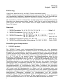
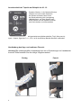
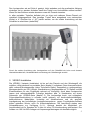
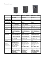
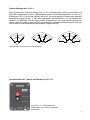
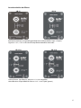
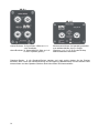
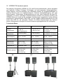
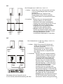
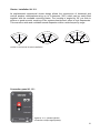
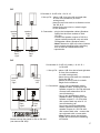
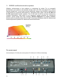
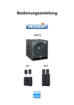
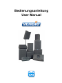
Bedienungsanleitung
User Manual
Deutsch
English ... page 22
Einführung
Vielen Dank, dass Sie sich für ein K.M.E. Produkt entschieden haben!
VERSIO wurde konsequent für portable Anforderungen entwickelt. Mit diesen kompakten
und ergonomisch gestalteten Lautsprechersystemen können Sie Ihren Beschallungssituationen flexibel entsprechen (Main-PA, Monitoring, Fillsystem, Delay-Line).
Wir verwenden in unseren umfangreichen Herstellungsprozessen ausschließlich geprüfte
Materialien und Komponenten bester Qualität. Teilen Sie mit uns die Begeisterung für
guten Sound. Das K.M.E. Team wünscht Ihnen viel Spaß, Freude und Erfolg mit Ihrem
neuen PA System!
Übersicht
I. VERSIO portable: VL 8 / VL 10 / VL 12 / VL 15 .…………… Seite 2-5
II. VERSIO Installation: VL 6 i / VL 8 i / VL 10 i /
VL 12 i / VL 15 i ……………….………. Seite 5-9
III. VERSIO Subwoofer: VB 15 / VB 15 w / VB 15 t / VB 215 /
VB 18 / VB 18 w .................................. Seite 10-14
IV. VERSIO PA-Systeme passiv: S1 / S2 / S4 ……………….…. Seite 15-17
V. VERSIO multifunktionelle Aktivsysteme: VL 240 / VL 250 .... Seite 18-20
Darstellung der Komponenten
I. VERSIO portable
Die VERSIO Topteile sind Hochleistungs-PA-Komponenten mit sehr kompakten
Abmessungen. Die Lautsprecher zeichnen sich durch ein transparentes und druckvolles
Klangbild bei ausgezeichneten akustischen Leistungsreserven aus und können als
Topteile, Monitore oder Fullrange oder in Kombination mit einem Subwoofer der VERSIO
Serie eingesetzt werden. Zur Auswahl stehen Lautsprecherchassis in den Varianten
8“ / 10“ / 12“ und 15“ als Neodym Treiber. Das Bassreflexgehäuse sorgt für eine
tieffrequente Abstrahlung ab 55 Hz. Der 1" - Hochtontreiber, der von der internen
Frequenzweiche angesteuert wird, ist in der 8“ +10“ Box an ein Waveguide mit 85° x 55°
gekoppelt und in der 12“ + 15“ Box an ein biradiales Horn. Zur Anpassung der
Abstrahlcharakteristik an das jeweilige Schallfeld lässt sich der portable Lautsprecher
mittels eines dreh- und kippbaren Flansches in 4° Schritten vertikal auf +/- 20° neigen.
Die VERSIO Topteile sind konzipiert für Anwendungen, bei denen es auf kontrollierte
Abstrahlcharakteristik im Hochtonbereich samt hohem Schalldruck bei geringstem
Platzbedarf ankommt. Das multifunktionelle Gehäuse mit asymmetrischem Monitorwinkel
(45°) sowie zwei M8 Montagepunkte im Deckel und die hochwertige kratz- und
schlagfeste Polyurethan-Beschichtung in schwarz bieten eine optimale Systemflexibilität
die absolut roadtauglich ist. Einen zusätzlichen Schutz bietet das hoch-schalldurchlässige,
ballwurfsichere Wabengitter, hinterlegt mit Akustikschaum und die spezielle
Imprägnierung der Lautsprechermembran gegen Feuchtigkeitseinflüsse. Als Anschlüsse
stehen 2 x Speakon NL 4 zur Verfügung, die den Lautsprecher auf 1+/1- ansteuern und
als Link weitergeschleift sind, 2+/2- ist für den Bi-Amp Betrieb ebenfalls verbunden.
2
Technische Daten:
VL 8 (8”+1”)
VL 10 (10”+1”)
VL 12 (12”+1”)
VL 15 (15”+1”)
Nenn.- / Prog.250 / 500 W
Belastbarkeit
350 / 700 W
350 / 700 W
400 / 800 W
Impedanz
(Ohm)
8
8
8
8
Frequenzgang
75 Hz - 19 kHz
60 Hz - 19 kHz
60 Hz - 19 kHz
55 Hz - 19 kHz
Trennfrequenz
2000 Hz
2000 Hz
2000 Hz
2000 Hz
Abstrahlwinkel
(h x v)
85° x 55°
(elliptisch)
85° x 55° (ellipt.)
drehbares Horn
75° x 45° (biradial) 75° x 45° (biradial)
Schalldruck
nom.
95 dB (1 W / 1 m) 96 dB (1 W / 1 m)
98 dB (1 W / 1 m)
100 dB
(1 W / 1 m)
Schalldruck
max.
119 dB Nennbelastbarkeit AES
121 dB Nennbelastbarkeit AES
123 dB Nennbelastbarkeit AES
126 dB Nennbelastbarkeit AES
Anschlüsse
2 x Speakon NL 4
(1+/1-) / (2+/2-)
2 x Speakon NL 4
(1+/1-) / (2+/2-)
2 x Speakon NL 4
(1+/1-) / (2+/2-)
2 x Speakon NL 4
(1+/1-) / (2+/2-)
Ausstattungsmerkmale
seitlich versenkter
Schalengriff, Hochständerflansch kipp
und rastbar +/- 20°,
2x M8
Montagepunkte
seitlich versenkter
Schalengriff, Hochständerflansch kipp
und rastbar +/- 20°,
2x M8
Montagepunkte
seitlich versenkter
Schalengriff, Hochständerflansch kipp
und rastbar +/- 20°,
2x M8
Montagepunkte
seitlich versenkte
Schalengriff, Hochständerflansch kipp
und rastbar +/- 20°,
2x M8
Montagepunkte
Maße in mm
(B x H x T)
280 x 460 x 245
330 x 580 x 340
390 x 610 x 360
445 x 700 x 425
Gewicht
9 kg
14 kg
15 kg
20 kg
Systemerweiterung
(Empfehlung)
Systemendstufe:
SMA 2000,
DA 428
Bass passiv
getrennt:
VB 15 t, VB 15 w
Bass aktiv
getrennt:
VB 15, VB 215
Systemendstufe:
SMA 2000,
DA 428
Bass passiv
getrennt:
VB 15 w, VB 18 w
Bass aktiv
getrennt:
VB 15, VB 215,
VB 18
Systemendstufe:
SMA 2000,
DA 428
Bass passiv
getrennt:
VB 15 w, VB 18 w
Bass aktiv
getrennt:
VB 15, VB 215,
VB 18
Systemendstufe:
SMA 2000,
DA 428
Bass passiv
getrennt:
VB 18 w
Bass aktiv
getrennt:
VB 215, VB 18
Zubehör
optional
Schutzhülle,
Montageplatte mit
TV-Zapfen
Schutzhülle,
Montageplatte mit
TV-Zapfen
Schutzhülle,
Montageplatte mit
TV-Zapfen
Schutzhülle,
Montageplatte mit
TV-Zapfen
3
Anschlussfeld der Topteile am Beispiel der VL 12:
Speakon-Stecker in die Speakon-Buchse
stecken und nach rechts drehen bis
der Stecker einrastet; beim Lösen
der Steckverbindung die Verriegelung
(Metallaufsatz) auf dem Stecker nach
hinten ziehen und den Speakon-Stecker
nach links drehen und herausziehen.
Buchsenanschlüsse sind parallel geschaltet zum Weiterschleifen (Top 8 Ohm passiv);
Input = Output, Signal an 1+/1-; 2+/2- ist für den Bi-Amp Betrieb ebenfalls verbunden.
Handhabung des kipp- und rastbaren Flansch:
Achtung! Bei unsachgemäßer Anwendung kann es zu Quetschungen im Handbereich
kommen. Bitte beachten Sie die richtige Vorgehensweise!
Richtig
4
Falsch!
Den Lautsprecher wie auf Seite 4 gezeigt, leicht anheben und die gewünschte Neigung
einstellen; bei zu starkem Anheben kann das Topteil vom Hochständer entfernt werden.
Wenn Sie das Gehäuse wieder absetzen muss der Flansch einrasten.
In allen portablen Topteilen befindet sich ein kipp und rastbarer Boxen-Flansch mit
variablem Neigungswinkel. Das jeweilige Topteil kann ausgehend vom senkrechten
Winkel in 4° Schritten bis +/- 20° justiert werden, um die exakte Ausrichtung auf das
Schallfeld zu erleichtern (siehe Bild).
Durch die exakte Ausrichtung des Lautsprechers auf das Schallfeld wird eine noch bessere
Abstrahlcharakteristik, Verständlichkeit und Nutzung der Schallenergie erreicht.
II. VERSIO Installation
Die VERSIO i-Variante (Installation) ist bis auf den Flansch und den Schalengriff, die
entfallen, völlig identisch zur portablen Serie (Kapitel 1) aufgebaut. Dem Anwender stehen
dafür mehrere Montagepunkte (siehe Technische Daten), kompatibel zu umfangreichem
Montagezubehör wie z.B. U-Bügel, Wandhalterung, Montageplatte mit TV-Zapfen und M8
Einschraubösen für den Flugbetrieb optional zur Verfügung. Auch diese Lautsprecher
lassen sich selbstverständlich Fullrange betreiben bzw. in Kombination mit einem
Subwoofer der VERSIO-Serie (Kapitel 3). Die hochwertige kratz- und schlagfeste
Polyurethan-Beschichtung in schwarz (weiß optional), ein hoch-schalldurchlässiges,
ballwurfsicheres Wabengitter, hinterlegt mit Akustikschaum und die spezielle
Imprägnierung der hochwertigen Lautsprechermembran gegen Feuchtigkeits-einflüsse
bieten optimalen Schutz, auch für Außeninstallationen. Als Anschlüsse stehen zwei
Schraubklemmen zur Verfügung (1+/1-). Optional besteht die Möglichkeit, ein
Anschlussfeld mit 2x Speakon NL 4 oder mit einer PG-Verschraubung einzusetzen. Der
Aufbau von 100 Volt ELA-Anlagen mit Anpassungsübertragern ist ebenfalls möglich.
5
Technische Daten:
VL 6 i (6”+1” Neodym)
VL 8 i (8”+1” Neodym)
VL 10 i (10”+1” Neodym)
200 / 400 W
250 / 500 W
350 / 700 W
Impedanz (Ohm) 8
8
8
Frequenzgang
80 Hz - 19 kHz
75 Hz - 19 kHz
60 Hz - 19 kHz
Trennfrequenz
2000 Hz
2000 Hz
2000 Hz
Abstrahlwinkel
(h x v)
85° x 55° (elliptisch)
85° x 55° (elliptisch)
85° x 55° (elliptisch),
drehbares Horn
Schalldruck
nominal
93 dB (1 W / 1 m)
95 dB (1 W / 1 m)
96 dB (1 W / 1 m)
Schalldruck
maximal
116 dB
Nennbelastbarkeit AES
119 dB
Nennbelastbarkeit AES
121 dB
Nennbelastbarkeit AES
Anschlüsse
2x Schraubklemmen,
2x Speakon optional,
1x PG - Verschraubung
optional
2x Schraubklemmen,
2x Speakon optional,
1x PG - Verschraubung
optional
2x Schraubklemmen,
2x Speakon optional,
1x PG - Verschraubung
optional
Oberfläche
PU Beschichtung
schwarz, weiß optional
PU Beschichtung
schwarz, weiß optional
PU Beschichtung
schwarz, weiß optional
Ausstattungsmerkmale
10 x M8 Montagepunkte
6 x M8 Montagepunkte
12 x M8 Montagepunkte
Maße in mm
(B x H x T)
235 x 405 x 190
280 x 460 x 245
330 x 580 x 340
Gewicht
7 kg
9 kg
14 kg
Systemerweiterung
(Empfehlung)
Systemendstufe:
SPA 500 F, DA 428
Bass passiv getrennt:
VB 15 t, VB 15 w
Bass aktiv getrennt:
VB 15, VB 215
Systemendstufe:
SMA 2000, DA 428
Bass passiv getrennt:
VB 15 t, VB 15 w,
VB 18 w
Bass aktiv getrennt:
VB 15, VB 215, VB 18
Systemendstufe:
SMA 2000, DA 428
Bass passiv getrennt:
VB 15 t, VB 15 w,
VB 18 w
Bass aktiv getrennt:
VB 15, VB 215, VB 18
Wandhalterung,
U-Bügel, Montageplatte
mit TV-Zapfen,
Reduzierflansch,
M8 Ringösen,
100 Volt Version
Wandhalterung,
U-Bügel, Montageplatte
mit TV-Zapfen, Stativadapter, M8 Ringösen,
Cluster-Montageplatte,
100 Volt Version
Belastbarkeit
(Nom. / Progr.)
Wandhalterung,
U-Bügel, L-Bügel,
Montageplatte mit TVZubehör optional
Zapfen, Reduzierflansch,
M8 Ringösen,
100 Volt Version
6
Belastbarkeit
(Nom. / Progr.)
VL 12 i (12”+1” Neodym)
VL 15 i (15”+1” Neodym)
350 / 700 W
400 / 800 W
Impedanz (Ohm) 8
8
Frequenzgang
60 Hz - 19 kHz
55 Hz - 19 kHz
Trennfrequenz
2000 Hz
2000 Hz
Abstrahlwinkel
(h x v)
75° x 45° (biradial)
75° x 45° (biradial)
Schalldruck
nominal
98 dB (1 W / 1 m)
100 dB (1 W / 1 m)
Schalldruck
maximal
123 dB
Nennbelastbarkeit AES
126 dB
Nennbelastbarkeit AES
Anschlüsse
2x Schraubklemmen,
2x Speakon optional,
1x PG - Verschraubung
optional
2x Schraubklemmen,
2x Speakon optional,
1x PG - Verschraubung
optional
Oberfläche
PU Beschichtung
schwarz, weiß optional
PU Beschichtung
schwarz, weiß optional
Ausstattungsmerkmale
6 x M8 Montagepunkte
4 x M6 + 4 x M8
Montagepunkte
Maße in mm
(B x H x T)
390 x 610 x 360
445 x 700 x 425
Gewicht
15 kg
20 kg
Systemerweiterung
(Empfehlung)
Systemendstufe:
SMA 2000, DA 428
Bass passiv getrennt:
VB 15 w, VB 18 w
Bass aktiv getrennt:
VB 15, VB 215, VB 18
Systemendstufe:
SMA 2000, DA 428
Bass passiv getrennt:
VB 18 w
Bass aktiv getrennt:
VB 215, VB 18
Wandhalterung,
U-Bügel, Montageplatte
Zubehör optional mit TV-Zapfen,
M8 Ringösen,
100 Volt Version
Wandhalterung,
U-Bügel, Montageplatte
mit TV-Zapfen,
M8 Ringösen,
100 Volt Version
7
Installationsvarianten am Beispiel der VL 6 i:
Vertikale oder horizontale Flugmontage
mit 3x M8 Ringösen
Vertikale oder horizontale Flugmontage mit
Montageplatte + TV-Zapfen + TV-Rohrkralle
Installation mit Wandhalter
Vertikale oder horizontale Installation mit U-Bügel
Anwendung auf dem Hochständer
mittels Reduzierflansch
L-Bügel VL 6 i (no.1-910-051);
U-Bügel VL 6 i (no.1-910-050), U-Bügel VL 8 i (no.1-910-043), U-Bügel VL 10 i (no. 1-910-056),
U-Bügel VL 12 i (no.1-910-044), U-Bügel VL 15 i (no.1-910-045);
Wandhalterung VL 6 i / VL 8 i / VL 10 i / VL 12 i (no.2-512-019),
Wandhalterung VL 15 i (no 2-512-021); Montageplatte mit TV-Zapfen (no.2-512-007);
Reduzierflansch (no. 2-430-003); Stativadapter (no. 2-512-003);
M8 Einschraubösen (no.5-350-000); Cluster-Montageplatte (no. 1-910-058)
8
Cluster-Montage der VL 10 i:
Das symmetrische Gehäuse-Design der VL 10 i ermöglicht den Aufbau horizontaler und
vertikaler Lautsprecher-Cluster (Schallampel) mittels Cluster-Montageplatte von bis zu 9
Elementen (360°). Der Cluster-Winkel ist mit 20° pro Seite definiert, sodass eine optimale
akustische Kopplung bei -6 dB des nominellen Abstrahlwinkels im Hochtonbereich
entsteht. So addieren sich die Pegel beider Lautsprecher (bei konstruktiver Interferenz)
derart, dass der gleiche Wert wie auf der jeweiligen Hauptabstrahlachse erzielt wird und
man erhält eine weitestgehend gleichmäßige Pegelverteilung.
80°
120°
160°
Vertikale oder horizontale Cluster-Montage
Anschlussfeld der Topteile am Beispiel der VL 12 i:
Signal an 1+/1- Schraubklemme
aufklemmen und immer sachgemäß
festdrehen.
9
III. VERSIO Subwoofer
Die Subwoofer der VERSIO-Serie sind besonders kompakt ausgeführt und mit großer
Leistungsfähigkeit für die Tieftonwiedergabe der VL-Lautsprecher konzipiert.
Das Bassreflexgehäuse sorgt für eine tieffrequente Abstrahlung ab 38 Hz und das
spezielle großflächige Tunneldesign ermöglicht hohen Schalldruck bei besonders
niedriger Powerkompression und geringem Strömungsgeräusch. Zur Auswahl stehen
Lautsprecherchassis in 15“ und 18“ Varianten, die von der internen Frequenzweiche, in
der w- und t- Ausführung angesteuert werden. Der VB 15, VB 18 und VB 215 müssen vor
der Endstufe mit einer aktiven Frequenzweiche bzw. durch einen Digitalcontroller
(z.B. DAP 26) im Frequenzgang getrennt werden. Die hochwertige kratz- und schlagfeste
Polyurethanbeschichtung bietet optimale Roadtauglichkeit. Einen zusätzlichen Schutz
bietet das schalldurchlässige, ballwurfsichere Wabengitter, hinterlegt mit Akustikschaum
und die spezielle Imprägnierung der Lautsprechermembran gegen Feuchtigkeitseinflüsse
z.B. bei Außenanwendungen. M10 Einschraubösen für die Flugmontage des VB 215 sind
optional erhältlich. Als Anschlüsse stehen Speakon NL 4 zur Verfügung, die den
Lautsprecher auf 1+/1- ansteuern und als Link weitergeschleift sind, 2+/2- ist für den BiAmp Betrieb im VB 15, VB 18 und VB 215 ebenfalls verbunden.
Technische Daten:
VB 15 (15“)
VB 18 (18“)
Nennbelastbarkeit /
Programmbelastbarkeit
500 / 1000 W
500 W / 1000 W
Impedanz (Ohm)
4
4 oder 8
Frequenzgang
40 Hz – 800 Hz (fx)
38 Hz – 800 Hz (fx)
Schalldruck nominal
100 dB (1 W / 1 m)
100 dB (1 W / 1 m)
Schalldruck maximal
127 dB Nennbelastbarkeit AES
127 dB Nennbelastbarkeit AES
Anschlüsse
2 x Speakon NL 4
(1+/1-) / (2+/2-)
2 x Speakon NL 4
(1+/1-) / (2+/2-)
Ausstattungsmerkmale
2 seitlich versenkte Schalengriffe, 2 seitlich versenkte Schalengriffe,
Flanschbuchse M20,
Flanschbuchse M20,
Stapelelemente
Stapelelemente
Maße in mm (B x H x T)
460 x 515 x 500
520 x 610 x 525
Gewicht
22 kg
27 kg
Systemerweiterung
(Empfehlung)
Systemendstufe:
SMA 2000, DA 428
Top aktiv getrennt:
VL 6 i, VL 8 - VL 8 i, VL 10 i,
VL 12 - VL 12 i / VL 240, VL 250
Systemendstufe:
SMA 2000, DA 428
Top aktiv getrennt:
VL 10 i, VL 12 - VL 12 i, VL 250
Zubehör optional
Schutzhülle
Schutzhülle
10
Technische Daten:
VB 15 w (15“)
VB 18 w (18“)
Nennbelastbarkeit /
Programmbelastbarkeit
500 / 1000 W
500 W / 1000 W
Impedanz (Ohm)
4
4
Frequenzgang
40 Hz – 130 Hz (fx)
38 Hz – 130 Hz (fx)
Schalldruck nominal
100 dB (1 W / 1 m)
100 dB (1 W / 1 m)
Schalldruck maximal
127 dB Nennbelastbarkeit AES
127 dB Nennbelastbarkeit AES
Anschlüsse
2 x Speakon NL 4
(1 x In + 1 x Out Topteil 8 Ohm)
2 x Speakon NL 4
(1 x In + 1 x Out Topteil 8 Ohm)
Ausstattungsmerkmale
2 seitlich versenkte Schalengriffe, 2 seitlich versenkte Schalengriffe,
Flanschbuchse M20,
Flanschbuchse M20,
Stapelelemente
Stapelelemente
Maße in mm (B x H x T)
460 x 515 x 500
520 x 610 x 525
Gewicht
26 kg
29 kg
Systemerweiterung
(Empfehlung)
Systemendstufe:
SMA 2000, DA 428
Top passiv getrennt:
VL 8 - VL 8 i, VL 10 i,
VL 12 - VL 12 i
Systemendstufe:
SMA 2000, DA 428
Top passiv getrennt:
VL 10 i, VL 12 - VL 12 i
Zubehör optional
Schutzhülle
Schutzhülle
Zubehör optional:
Schutzhüllen:
VB 15 (no.2-311-052)
VB 18 (no.2-311-053)
11
Technische Daten:
VB 15 t (15“ Doppelspule)
VB 215 (2 x 15“)
Nennbelastbarkeit /
Programmbelastbarkeit
2 x 400 W / 2 x 800 W
1000 W / 2000 W
Impedanz (Ohm)
2x4
4
Frequenzgang
40 Hz – 130 Hz (fx)
40 Hz – 800 Hz (fx)
Schalldruck nominal
100 dB (1 W / 1 m)
104 dB (1 W / 1 m)
Schalldruck maximal
127 dB Nennbelastbarkeit AES
134 dB Nennbelastbarkeit AES
Anschlüsse
4 x Speakon NL 4
(2 x In + 2 x Out Topteil 8 Ohm)
2 x Speakon NL 4
(1+/1-) / (2+/2-)
Ausstattungsmerkmale
2 seitlich versenkte Schalengriffe, 2 seitlich versenkte Schalengriffe,
Flanschbuchse M20,
9 x M10 Montagepunkte,
Stapelelemente
Stapelelemente
Maße in mm (B x H x T)
460 x 515 x 500
1010 x 460 x 495
Gewicht
32 kg
41 kg
Systemerweiterung
(Empfehlung)
Systemendstufe:
SMA 2000, DA 428
Top passiv getrennt:
VL 6 i, VL 8 - VL 8 i
Systemendstufe:
SMA 2000, DA 428
Top aktiv getrennt:
VL 8 - VL 8 i, VL 10 i,
VL 12 - VL 12 i, VL 240, VL 250
Zubehör optional
Schutzhülle
M10 Einschraubösen
(no.4-240-305)
12
Anschlussfelder der Bässe:
VB 15
VB 18
Buchsenanschlüsse sind parallel geschaltet zum weiterschleifen; Input = Output;
Signal an 1+/1-; 2+/2- ist für den Bi-Amp Betrieb ebenfalls verbunden
VB 15 w
VB 18 w
untere Buchse: Input Bass 4 Ohm an 1+/1- vom Verstärker
obere Buchse: Output Mid/Hi 8 Ohm an 1+/1- zum Topteil (passiv)
13
VB 15 t
VB 215
untere Buchsen: 2x Input Bass 4 Ohm an 1+/1vom Verstärker
obere Buchsen: 2x Output Mid/Hi 8 Ohm an 1+/1zu den Topteilen (passiv)
Buchsenanschlüsse sind parallel geschaltet
zum weiterschleifen; Input = Output;
Signal an 1+/1-; 2+/2- ist für den Bi-Amp
Betrieb ebenfalls verbunden
Speakon-Stecker in die Speakon-Buchse stecken und nach rechts drehen bis der Stecker
einrastet; beim Lösen der Steckverbindung die Verriegelung (Metallaufsatz) auf dem Stecker nach
hinten ziehen und den Speakon-Stecker nach links drehen und herausziehen.
14
IV. VERSIO PA-Systeme passiv
Die passiven PA-Systeme VERSIO S1, S2 und S4 sind professionelle, extrem kompakte
und kraftvolle 3-Wege Fullrange PA-Anlagen mit hervorragenden Klangergebnissen.
Diese Systeme, sind die passende wie funktionelle Antwort auf Aufgabenstellungen im
mobilen Einsatz sowie im Installationsbereich. Einfache Sprachübertragung, Fill- oder
Delay-Systeme, Präsentation, Musikverstärkung mit oder ohne Subwoofer als Main-PA,
unterstützt von einem vielseitigen Zubehörsortiment erlauben die passiven Systeme der
VERSIO-Serie eine exakt an die jeweiligen Anforderungen angepasste Lösung. Mit der
empfohlenen Systemendstufe SMA 2000 und der digitalen Mehrkanalendstufe DA 428
sowie dem DAP 26, als optionalen Zubehör für flexible Erweiterungen der Systeme
stehen umfangreiche Lösungen für diverse Ansteuerungsmöglichkeiten zur Verfügung.
Technische Daten:
S1
S2
S4
Systemkomponenten
2 x VL 8 (8“+1“),
1 x VB 15 t
(15“ Doppelspule)
2 x VL 12 (12“+1“),
2 x VB 18 w (18“)
2 x VL 12 (12“+1“),
2 x VB 18 (18“/ 4 Ohm),
1 x DA 428
Systembelastbarkeit
2 x 650 W (AES)
2 x 850 W (AES)
2 x 850 W (AES);
(2 x 500 W + 2 x 350 W)
Frequenzgang
40 Hz – 19 KHz
38 Hz – 19 KHz
38 Hz – 19 KHz
Anschlüsse
Speakon NL 4 (1+/1-)
Speakon NL 4 (1+/1-)
Speakon NL 4 (1+/1-)
Gewichte der
Komponenten
Top: 2 x 9 kg
Bass: 1 x 32 kg
Top: 2 x 15 kg
Bass: 2 x 29 kg
Top: 2 x 15 kg
Bass: 2 x 27 kg
Endstufe: 8,5 kg
Empfohlen für
Entertainer, Duos
Bands, mobile DJs
Bands & mobile DJs,
Verleiher
Zubehör optional
Plug & Play Pack
(no.2-521-005),
Cover Pack
(no.2-312-014)
Plug & Play Pack
(no.2-521-006),
Cover Pack
(no.2-312-015)
Plug & Play Pack
(no.2-521-009),
Cover Pack
(no.2-312-015)
S1*
S2*
S4*
15
Aufstellung und Verkabelung der PA Systeme:
Hinweis!
Beachten Sie die gezielte und sinnvolle Aufstellung hochwertiger Lautsprechersysteme.
Eine allgemeingültige Aussage über eine korrekte (Standard)- Einstellung und Aufstellung
der PA-Anlagen ist unmöglich, da jede Beschallung an einen unterschiedlichen Ort
gebunden ist und somit immer andere Eigenschaften aufweist.
Bei der Benutzung von Boxenstativen sowie Distanzelementen für Topteile muss die
Standsicherheit in jedem Fall vom Anwender gewährleistet werden. Verwenden Sie für
den evtl. Flugbetrieb der Topteile nur geprüfte Anschlagmittel, um stets die max.
Sicherheit zu gewährleisten (auch hier trägt der Anwender die volle Verantwortung).
Verwenden Sie niemals Zusatzvorrichtungen, die nicht vom Hersteller empfohlen wurden,
weil dadurch Unfälle verursacht werden können.
Je nach Beschaffenheit der zu beschallenden Fläche / Räume kann man die Topteile
horizontal etwas eindrehen bzw. auch vertikal neigen, um Schallreflektionen (z.B. an
Wänden + Decken) und damit verbundene Interferenzen zu verringern und somit eine
bessere Nutzung der Schallenergie zu erhalten.
Wenn Abdeckungen geöffnet oder Gehäuseteile entfernt werden, außer wenn
dies von Hand möglich ist, können Teile freigelegt werden, die Spannung führen. Wenn
ein Öffnen des Gerätes erforderlich ist, muss das Gerät von allen Spannungsquellen
getrennt sein.
Hohe Lautstärkepegel können dauernde Gehörschäden verursachen. Vermeiden Sie
deshalb die direkte Nähe von Lautsprechern, die mit hohen Pegeln betrieben werden.
Verwenden Sie einen Gehörschutz bei dauernder Einwirkung hoher Pegel.
S1*
Die S1 besteht aus: 1x VB 15 t + 2x VL 8
1. Aufbau: - Stellen Sie den VB 15 t links oder rechts vor die
zu beschallende Fläche auf festen Untergrund
- jetzt wird ein Topteil auf eine Distanzstange auf den
VB 15 t gestellt und das zweite Topteil auf einen
Hochständer (links bzw. rechts vor die zu
beschallende Fläche, Front auf einer Linie)
- die Topteile werden in entsprechender Höhe fixiert
speaker speaker
output
output
“right”
“left”
speaker speaker
input
input
“right”
“left”
16
2. Anschluss: - Stecken Sie die zwei Lautsprecherkabel
(Speakon-Kabel) von der Endstufe kommend
in die zwei unteren Lautsprechereingänge am
Anschlussfeld des VB 15 t an
- Verbinden Sie nun den Lautsprecherausgang
„Right“ bzw. „Left“ der VB 15 t mit dem jeweiligen
Topteil mit einem Speakon-Kabel (bitte beachten
Sie links + rechts!)
- Hinweis! Achten Sie bitte beim Einschalten der
Systemendstufe darauf, dass alle Lautstärkeregler auf Position 0/Linksanschlag gedreht sind,
um eine unerwünschte Wiedergabe zu vermeiden
S2*
Die S2 besteht aus: 2x VB 18 w + 2x VL 12
1. Aufbau: - Stellen Sie je einen VB 18 w links und rechts
vor die zu beschallende Fläche auf festen
Untergrund
- jetzt wird jeweils ein Topteil auf eine
Distanzstange auf den VB 18 w gestellt
- die Topteile werden in entsprechender Höhe
fixiert
speaker
output
“right”
speaker
input
“right”
speaker
output
“left”
speaker
input
“left”
2. Anschluss: - Stecken Sie je ein Lautsprecherkabel
(Speakon-Kabel) von der Endstufe
kommend in die unteren Lautsprechereingänge am Anschlussfeld der VB 18 w an
- Verbinden Sie nun den Lautsprecherausgang der VB 18 w jeweils mit einem
Topteil mit einem Speakon-Kabel
- Hinweis! Achten Sie bitte beim Einschalten der Systemendstufe darauf, dass
alle Lautstärkeregler auf Position 0/Linksanschlag gedreht sind, um eine
unerwünschte Wiedergabe zu vermeiden
S4*
Die S4 besteht aus: 2x VB 18 (4 Ohm) + 2x VL 12 +
1x DA 428
speaker
input
“right”
speaker
input
“left”
1. Aufbau: - Stellen Sie je einen VB 18 links und
rechts vor die zu beschallende Fläche
auf festen Untergrund
- jetzt wird jeweils ein Topteil auf eine
Distanzstange auf den VB 18 gestellt
- die Topteile werden in entsprechender
Höhe fixiert
2. Anschluss: - Stecken Sie je ein Lautsprecherkabel
(Speakon-Kabel, 2-polig) an den Lautsprecherausgang A + B der DA 428
& verbinden Sie damit jeweils einen
Subwoofer VB 18 (siehe Bild links)
- Stecken Sie je ein Lautsprecherkabel
(Speakon-Kabel, 2-polig) an den Lautsprecherausgang C + D der DA 428 &
speaker
speaker
verbinden Sie damit jeweils ein Topteil
input
input
VL 12 (siehe Bild links) oder
“right”
“left”
schließen Sie je ein 4-poliges Lautsprecherkabel (Speakon-Kabel) an den
A B
C D
Lautsprecherausgang A + B der DA 428
an & verbinden Sie damit je einen VB 18;
die Topteile werden jeweils mit einem
Kreuzkabel am Sub. angeschlossen
- Hinweis! Achten Sie bitte beim EinschalBitte wählen Sie das Preset für die S4
ten der DA 428 darauf, dass alle angean der DA 428 (siehe Bedienanleitung DA 428)!
schlossenen Geräte vorher gemutet sind
17
V. VERSIO multifunktionelle Aktivsysteme
Ob Beschallung des Publikums oder Monitoring für Künstler: für einen gelungenen Auftritt
ist eins so wichtig wie das andere. Wer jemals live gespielt hat, ohne sich selbst und /oder
die Band ausreichend zu hören, weiß, wie entscheidend ein guter Monitorsound für die
perfekte Performance ist. Darum bietet K.M.E. mit dem VL 240 und dem VL 250
ausgereifte Monitorsysteme an, welche in Sound und Leistung höchsten Ansprüchen
gerecht werden. Der VL 240 und der VL 250 überzeugen nicht allein durch enorm
kompakte Abmessungen, sondern durch hohe Leistung bei enormer Gewichtsreduzierung
durch Neodymbestückung, optischen Design und einfachste Bedienung. Ein definiertes
Abstrahlverhalten für höchste Rückkopplungssicherheit auch bei extremen Pegeln und
nicht zuletzt die klangliche Brillanz bieten eine so effiziente wie neutrale Arbeitsplattform
für Künstler und Tontechniker.
Das Bedienfeld:
Am Beispiel des VL 240 (Das Bedienfeld des VL 240 und VL 250 ist identisch).
8.
1. 2.
18
3.
9.
4.
10.
5.
11. 9.
6.
4.
10.
7.
Netz
1. GROUND/FREE Schalter (trennt die Masse der Eingangsbuchsen vom Gehäuse zur
Vermeidung von Brummschleifen)
2. Netzanschlussbuchse mit Sicherungshalter (als Ersatz darf nur der neben der Netzbuchse
aufgedruckte Sicherungswert eingesetzt werden), Achtung: korrekte Netzspannung von
230 V AC verwenden
3. Netzschalter beleuchtet (wenn der Schalter beim Einschalten nicht leuchtet prüfen Sie bitte Ihre
Spannungsquelle bzw. die Sicherung). Hinweis: Bitte alle Lautstärkeregler beim Einschalten der
Box auf Position 0 (Linksanschlag) drehen, um eine unerwünschte Wiedergabe zu vermeiden; im
Betriebszustand darauf achten, dass der Lautstärkeregler des nichtbenutzten Eingangs ebenfalls
auf Position 0 steht, um unnötiges Rauschen zu vermeiden
Anschluss
4. LINE IN (XLR-Buchse) symmetrisch; 11.schaltet die Empfindlichkeit des zweiten Kanals
zwischen MIC und LINE um
5. LINK Ausgang (XLR-Stecker) symmetrisch, zum Weiterschleifen des Signals des ersten
Kanals, ohne Auswirkung der Klangregelung
6. CINCH Eingang, parallel zum LINE IN Eingang im ersten Kanal, geeignet z. B. zum Anschluss
eines CD-/ MP3-Players
7. LINE IN (Klinkenbuchse) symmetrisch
Bedienung
8. LIMIT/PEAK Anzeige (bei nahezu ständigem Aufleuchten der LED den Signalpegel bitte
reduzieren, da sonst ein eventueller Folgeschaden der Elektronik und des Lautsprechers nicht
auszuschließen ist)
9. Lautstärkeregler des jeweiligen Kanals
10. Klangregler (Bass und Höhen) des jeweiligen Kanals
Anschlussübersicht von symmetrischen u. unsymmetrischen Leitungen:
19
Technische Daten:
VL 240 (8“+1“)
VL 250 (12“+1“)
Nennbelastbarkeit
200 W Bass/Mid + 50 W High
200 W Bass/Mid + 50 W High
Verstärker
Class D / Class D
Class D / Class D
Abstrahlcharakteristik
85° x 55° elliptisch
75° x 45° biradial
Frequenzgang
70 Hz – 19 KHz
60 Hz – 19 KHz
Trennfrequenz
2000 Hz
2000 Hz
Schalldruck nominal
95 dB (1 W / 1 m)
98 dB (1 W / 1 m)
Schalldruck maximal
120 dB Nennbelastbarkeit AES
123 dB Nennbelastbarkeit AES
Anschlüsse
Mic-In XLR, 2x Line-In
Mic-In XLR, 2x Line-In
XLR/Klinke, Cinch, Line-Out XLR XLR/Klinke, Cinch, Line-Out XLR
Ausstattungsmerkmale
seitlich versenkter Riemengriff,
Hochständerflansch kipp und
rastbar +/- 20°,
4 x M8 Montagepunkte
seitlich versenkter Schalengriff,
Hochständerflansch kipp und
rastbar +/- 20°,
4 x M8 Montagepunkte
Maße in mm (B x H x T) 280 x 460 x 245 mm
390 x 610 x 360 mm
Gewicht
11,5 kg
18 kg
Zubehör optional
Wandhalterung (no.2-512-019),
Universalmontageplatte mit TVZapfen (no.2-512-007),
M8 Ringösen (no.5-350-000),
Schutzhülle (no. 2-311-049)
Wandhalterung (no.2-512-019),
Universalmontageplatte mit TVZapfen (no.2-512-007),
M8 Ringösen (no.5-350-000),
Schutzhülle (no. 2-311-054)
20
Notizen / Notes:
21
English
Deutsch … Seite 2
Introduction
Thank you for choosing a K.M.E. product!
VERSIO has been developed consequently to portable requirements. With these compact
and ergonomic loudspeaker systems you will be able to master your reinforcement
situations in a very flexible manner (main-PA, monitoring, fill-system).
Within our extensive production processes we only use exclusive materials and
components of best quality. Share with us the enthusiasm for good sound. The K.M.E.
team wishes you fun, joy and success with your new PA-system!
Contents
I. VERSIO portable: VL 8 / VL 10 / VL 12 / VL 15 ..…………… page 22-25
II. VERSIO installation: VL 6 i / VL 8 i / VL 10 i /
VL 12 i / VL 15 i ………………….…….. page 25-29
III. VERSIO subwoofer: VB 15 / VB 15 w / VB 15 t / VB 215
VB 18 / VB 18 w ……………………….. page 30-34
IV. VERSIO PA systems passive: S1 / S2 / S4 …………………. page 35-37
V. VERSIO multifunctional active systems: VL 240 / VL 250 .... page 38-40
Presentation of the components
I.
VERSIO portable
The VERSIO top units are high powered PA system components with very compact
dimensions. The loudspeakers are characterised by their transparent and powerful sound
with excellent acoustic power reserves and can be used as top unit, full-range or floor
monitor or in combination with VERSIO subwoofers. You can choose loudspeaker
neodymium chassis in 8" / 10” / 12" and 15" variants. The bass reflex housing provides a
low-frequent radiation starting from 55 Hz. The 1" high frequency driver is coupled to a
Waveguide in the 8" / 10” box with 85° x 55° and to a bi-radial horn in the 12" / 15" box,
which are controlled by the internal crossover. All top units include a swivelling flange with
a variable tilt angle. For the adjustment of the dispersion characteristic the top parts can
be adjusted in 4° steps within +/- 20° to facilitate an exact alignment to the audience. The
VERSIO-series is designed for applications achieving a controlled radiation characteristic
in the high level range including high sound pressure with smallest dimensions. The multifunctional casing with asymmetrical monitor angle (45°) and an adjustable flange as well
as high-quality scratch- and impact-resistant PU coating and a protective grille with
perforated steel with acoustic foam offers best road suitability. As connections
2 x Speakon NL 4 are available, driving the loudspeaker on 1+/1- and linking it, also 2+/2-,
for the bi-amp mode.
22
Technical specifications:
VL 8 (8”+1”)
VL 10 (10”+1”)
VL 12 (12”+1”)
VL 15 (15”+1”)
Nominal load /
Program load
250 / 500 W
350 / 700 W
350 / 700 W
400 / 800 W
Impedance
(Ohm)
8
8
8
8
Frequency
range
75 Hz - 19 kHz
60 Hz - 19 kHz
60 Hz - 19 kHz
55 Hz - 19 kHz
Crossover
freuquency
2000 Hz
2000 Hz
2000 Hz
2000 Hz
Dispersion
(h x v)
85° x 55°
(elliptical)
85° x 55° (elliptic.) 75° x 45°
rotatable horn
(bir-adial)
SPL nominal
95 dB (1 W / 1 m) 96 dB (1 W / 1 m)
SPL max.
119 dB
121 dB
123 dB
126 dB
Nominal load AES Nominal load AES Nominal load AES Nominal load AES
Connectors
2 x Speakon NL 4
(1+/1-) / (2+/2-)
2 x Speakon NL 4
(1+/1-) / (2+/2-)
2 x Speakon NL 4
(1+/1-) / (2+/2-)
2 x Speakon NL 4
(1+/1-) / (2+/2-)
Features
side-mounted
handle, swivelling
flange with variable
tilt angle +/- 20°,
2 x M8 treads
side-mounted
handle, swivelling
flange with variable
tilt angle +/- 20°,
2 x M8 treads
side-mounted
handle, swivelling
flange with variable
tilt angle +/- 20°,
2 x M8 treads
2 side-mounted
handles, swivelling
flange with variable
tilt angle +/- 20°,
2 x M8 treads
Dimensions in
280 x 460 x 245
mm (W x H x D)
330 x 580 x 340
390 x 610 x 360
445 x 700 x 425
Weight
9 kg
14 kg
15 kg
20 kg
Systemextension
(recommendation)
system amplifier:
SMA 2000,
DA 428
passively
channelled:
VB 15 t, VB 15 w
actively
channelled:
VB 15, VB 215
system amplifier:
SMA 2000,
DA 428
passively
channelled:
VB 15 t, VB 15 w
actively
channelled:
VB 15, VB 215,
VB 18
system amplifier:
SMA 2000,
DA 428
passively
channelled:
VB 15 w, VB 18 w
actively
channelled:
VB 15, VB 215,
VB 18
system amplifier:
SMA 2000,
DA 428
passively
channelled:
VB 18 w
actively
channelled:
VB 215, VB 18
Optional
accessories
protective cover,
universal mounting
plate with TV
spigot
protective cover,
universal
mounting plate
with TV spigot
protective cover,
universal
mounting plate
with TV spigot
protective cover,
universal
mounting plate
with TV spigot
98 dB (1 W / 1 m)
75° x 45°
(bi-radial)
100 dB
(1 W / 1 m)
23
Connection panel VL 12:
Plug in the Speakon connector into the
Speakon socket and turn right to snap in,
when disconnect pull locking device backwards
and turn left to pull out the plug.
connection sockets are parallel to reconnect a top unit (passive, impedance 8 Ohm);
input = output; signal at 1+/1-, 2+/2- for the bi-amp mode
The swivelling flange with a variable tilt angle:
Attention! An incorrect use can cause bruises on your hands.
Please follow the instructions!
correct
24
wrong!
Please lift up the loudspeaker slightly and justify it in the right declination as shown on
page 20. When lifting up the speaker too hard it can be removed from the high stand.
If you set down the box on the high stand, the flange must snap in.
All top units include a swivelling flange with a variable tilt angle. The top parts can be
adjusted in 4° steps within +/- 20° to facilitate an exact alignment to the audience
(see drawing).
The accurate adjustment of the box onto the sound area provides a better dispersion ,
comprehensibility and better utilization of sound energy.
II. VERSIO installation
The VERSIO-installation series is completely identical to the portable series (chapter 1)
except the flange and the side mounted handle, which are cancelled. Therefore the
systems include treads (see technical specifications), to adapt a wall mount, a u-bracket,
a universal mounting plate with TV-spigot or eyebolts (optional) for the flying operation.
Also these top units can be used as full-range or in combination with a VERSIO
subwoofer (chapter 3). High-quality scratch and impact-resistant PU coating in black
(white optional) as well as a protective grille with perforated steel with acoustic foam offer
best protection. The special impregnation of the loudspeaker diaphragm against moisture
effects provide optimal protection also for external installations. As connections screw
connectors are available (optional you can choose a terminal with 2 x Speakon NL 4 or a
terminal with PG plug). Adaption transmitters are available in 120 W and 240 W for the
installation of 100 Volt ELA systems.
25
Technical specifications:
VL 6 i (6”+1”)
VL 8 i (8”+1”)
VL 10 i (10”+1”)
Nominal load /
Programm load
200 / 400 W
250 / 500 W
350 / 700 W
Impedance
(Ohm)
8
8
8
Frequency
range
80 Hz - 19 kHz
75 Hz - 19 kHz
60 Hz - 19 kHz
Crossover
freuquency
2000 Hz
2000 Hz
2000 Hz
Dispersion
(h x v)
85° x 55° (elliptical)
85° x 55° (elliptical)
85° x 55° (elliptical)
rotatable horn
SPL nominal
93 dB (1 W / 1 m)
95 dB (1 W / 1 m)
96 dB (1 W / 1 m)
SPL max.
116 dB
Nominal load AES
119 dB
Nominal load AES
121 dB
Nominal load AES
Connectors
2x terminal screw
connectors,
2x Speakon NL 4
optional,
1x PG - plug optional
2x terminal screw
connectors,
2x Speakon NL 4
optional,
1x PG - plug optional
2x terminal screw
connectors,
2x Speakon NL 4
optional,
1x PG - plug optional
Finish
PU coating black,
white optional
PU coating black,
white optional
PU coating black,
white optional
Features
10 x M8 treads
6 x M8 treads
12 x M8 treads
Dimensions in
mm (W x H x D)
235 x 405 x 190
280 x 460 x 245
330 x 580 x 340
Weight
7 kg
9 kg
14 kg
Systemextension
(recommendation)
system amplifier:
SPA 500 F, DA 428
passively channelled:
VB 15 t, VB 15 w
actively channelled:
VB 15, VB 215
system amplifier:
SMA 2000, DA 428
passively channelled:
VB 15 t, VB 15 w,
VB 18 w
actively channelled:
VB 15, VB 215, VB 18
system amplifier:
SMA 2000, DA 428
passively channelled:
VB 15 t, VB 15 w,
VB 18 w
actively channelled:
VB 15, VB 215, VB 18
Optional
accessories
speaker wall mount,
U-bracket, L-bracket,
M8 eyebolts, universal
mounting plate with TV
spigot,
100 Volt transformer
speaker wall mount,
U-bracket,
M8 eyebolts, universal
mounting plate with TV
spigot,
100 Volt transformer
speaker wall mount,
U-bracket, M8 eyebolts,
universal mounting plate
with TV spigot, cluster
mounting plate,
100 Volt transformer
26
VL 12 i (12”+1”)
VL 15 i (15”+1”)
Nominal load /
Programm load
350 / 700 W
400 / 800 W
Impedance
(Ohm)
8
8
Frequency
range
60 Hz - 19 kHz
55 Hz - 19 kHz
Crossover
freuquency
2000 Hz
2000 Hz
Dispersion
(h x v)
75° x 45°
(bi-radial)
75° x 45°
(bi-radial)
SPL nominal
98 dB (1 W / 1 m)
100 dB (1 W / 1 m)
SPL max.
123 dB
Nominal load AES
126 dB
Nominal load AES
Connectors
2x terminal screw
connectors,
2x Speakon NL 4
optional,
1x PG - plug optional
2x terminal screw
connectors,
2x Speakon NL 4
optional,
1x PG - plug optional
Finish
PU coating black,
White optional
PU coating black,
White optional
Features
6 x M8 treads
4 x M6 and 4 x M8 treads
Dimensions in
mm (W x H x D)
390 x 610 x 360
445 x 700 x 425
Weight
15 kg
20 kg
Systemextension
(recommendation)
system amplifier:
SMA 2000, DA 428
passively channelled:
VB 15 w, VB 18 w
actively channelled:
VB 15, VB 215, VB 18
system amplifier:
SMA 2000, DA 428
passively channelled:
VB 18 w
actively channelled:
VB 215, VB 18
Optional
accessories
speaker wall mount,
U-bracket,
M8 eyebolts, universal
mounting plate with TV
spigot,
100 Volt transformer
speaker wall mount,
U-bracket,
M8 eyebolts, universal
mounting plate with TV
spigot,
100 Volt transformer
27
Installation examples of VL 6 i:
vertical or horizontal installation
with 3x M8 eyebolts
vertical or horizontal installation with
mounting plate + TV-spigot + truss adapter
installation with wall mount
vertical or horizontal installation with U-bracket
application on high stand
using reducer flange
L-bracket VL 6 i (no.1-910-051);
U-bracket VL 6 i (no.1-910-050), U-bracket VL 8 i (no.1-910-043), U-bracket VL 10 i
(no. 1-910-056), U-bracket VL 12 i (no.1-910-044), U-bracket VL 15 i (no.1-910-045);
wall mount VL 6 i / VL 8 i / VL 10 i / VL 12 i (no.2-512-019), wall mount VL 15 i (no 2-512-021);
mounting plate with TV-spigot (no.2-512-007); reducer flange (no. 2-430-003);
adapter for high stand (no. 2-512-003); M8 eyebolts (no.5-350-000),
cluster mounting plate (no. 1-910-058)
28
Cluster- installation VL 10 i:
Its sophisticated symmetrical cluster design allows the construction of horizontal and
vertical speaker combinations using up to 9 elements (360°) which can be easily fitted
together with the available mounting plates. The housing is angled by 20° per side to
achieve a good acoustic coupling of two systems beside each other in high frequencies.
This ensures a wide and consistent sound dispersion within a wide frequency range.
120°
80°
160°
vertical or horizontal cluster-installation
Connection panel VL 12 i :
signal at 1+/1-; please tight the
connection clamps appropriately
29
III. VERSIO subwoofer
The VERSIO subwoofers are high powered PA system components with very compact
dimensions and large efficiency for the gravity support of the VL-loudspeakers. The bass
reflex housing provides a low-frequent radiation starting from 38 Hz. The special wide
tunnel design enables a high sound pressure with extra low power compression and a low
flow noise. You can choose loudspeaker chassis in 15" and 18" variants. The “w” and ”t”
version have an integrated frequency crossover. The VB 15, VB 18 and VB 215 must be
separated before the amp with an active crossover or a digital controller (for example DAP
26). M10 eyebolts for flying the VB 215 are available as an option. High-quality scratchand impact-resistant PU coating and protective grille with perforated steel with acoustic
foam offer best protection and road suitability. The special impregnation of the
loudspeaker diaphragm against moisture effects protect the systems for outside
applications. As connections 2 x Speakon NL 4 are available, driving the loudspeaker on
1+/1- and linking it, also 2+/2-, for the bi-amp mode of the VB 15, VB 18 and VB 215.
Technical specifications:
VB 15 (15“)
VB 18 (18“)
Nominal load /
Programm load
500 / 1000 W
500 W / 1000 W
Impedance (Ohm)
4
4 or 8
Frequency range
40 Hz – 800 Hz (fx)
38 Hz – 800 Hz (fx)
SPL nominal
100 dB (1 W / 1 m)
100 dB (1 W / 1 m)
SPL max.
127 dB Nominal load AES
127 dB Nominal load AES
Connectors
2 x Speakon NL 4
(1+/1-) / (2+/2-)
2 x Speakon NL 4
(1+/1-) / (2+/2-)
Features
2 side-mounted handles,
M20 fixing plate,
stacking elements
2 side-mounted handles,
M20 fixing plate,
stacking elements
Dimensions in mm
(W x H x D)
460 x 515 x 500
520 x 610 x 525
Weight
22 kg
27 kg
System extension
(recommendation)
system amplifier:
SMA 2000, DA 428
actively channelled:
VL 6 i, VL 8 - VL 8 i, VL 10 i,
VL 12 - VL 12 i / VL 240, VL 250
system amplifier:
SMA 2000, DA 428
actively channelled:
VL 10 i, VL 12 - VL 12 i, VL 250
Optional accessories
protective cover
protective cover
30
Technical specifications:
VB 15 w (15“)
VB 18 w (18“)
Nominal load /
Programm load
500 / 1000 W
500 W / 1000 W
Impedance (Ohm)
4
4
Frequency range
40 Hz – 130 Hz (fx)
38 Hz – 130 Hz (fx)
SPL nominal
100 dB (1 W / 1 m)
100 dB (1 W / 1 m)
SPL max.
127 dB Nominal load AES
127 dB Nominal load AES
Connectors
2 x Speakon NL 4
(1 x in + 1 x out top unit 8 Ohm)
2 x Speakon NL 4
(1 x in + 1 x out top unit 8 Ohm)
Features
2 side-mounted handles,
M20 fixing plate,
stacking elements
2 side-mounted handles,
M20 fixing plate,
stacking elements
Dimensions in mm
(W x H x D)
460 x 515 x 500
520 x 610 x 525
Weight
26 kg
29 kg
System extension
(recommendation)
system amplifier:
SMA 2000, DA 428
passively channelled:
VL 8 - VL 8 i, VL 10 i,
VL 12 - VL 12 i
system amplifier:
SMA 2000, DA 428
passively channelled:
VL 10 i, VL 12 - VL 12 i
Optional accessories
protective cover
protective cover
Optional accessories:
Protective covers:
VB 15 (no.2-311-052)
VB 18 (no.2-311-053)
31
Technical specifications:
VB 15 t (15“ twin coil)
VB 215 (2 x 15“)
Nominal load /
Programm load
2 x 400 W / 2 x 800 W
1000 W / 2000 W
Impedance (Ohm)
2x4
4
Frequency range
40 Hz – 130 Hz (fx)
40 Hz – 800 Hz (fx)
SPL nominal
100 dB (1 W / 1 m)
104 dB (1 W / 1 m)
SPL max.
127 dB Nominal load AES
134 dB Nominal load AES
Connectors
4 x Speakon NL 4
(2 x in + 2 x out top unit 8 Ohm)
2 x Speakon NL 4
(1+/1-) / (2+/2-)
Features
2 side-mounted handles,
M20 fixing plate,
stacking elements
2 side-mounted handles,
9 x M10 treads,
stacking elements
Dimensions in mm
(W x H x D)
460 x 515 x 500
1010 x 460 x 495
Weight
32 kg
41 kg
System extension
(recommendation)
system amplifier:
SMA 2000, DA 428
passively channelled:
VL 6 i, VL 8 - VL 8 i
system amplifier:
SMA 2000, DA 428
actively channelled:
VL 8 - VL 8 i, VL 10 i,
VL 12 - VL 12 i, VL 240, VL 250
Optional accessories
protective cover
M10 eyebolts (no.4-240-305)
32
Connection panel of the subs:
VB 15
VB 18
connection sockets are parallel to reconnect a sub; input = output; signal at 1+/1-;
2+/2- is also reconnected for the bi-amp mode
VB 15 w
VB 18 w
lower socket: input sub 4 ohm at 1+/1- from the amplifier
upper socket: output Mid/Hi 8 ohm at 1+/1- to the top unit (passive)
33
VB 15 t
VB 215
lower sockets: 2x input sub 4 ohm at 1+/1from the amplifier
upper sockets: 2x output Mid/Hi 8 ohm at 1+/1to the top units (passive)
connection sockets are parallel to reconnect
a sub; input = output; signal at 1+/1-;
2+/2- is also reconnected for the bi-amp mode
Plug in the Speakon connector into the Speakon socket and turn right to snap in, when disconnect
pull locking device backwards and turn left to pull out the plug.
34
IV. VERSIO PA-systems passive
The passive PA systems VERSIO S1, S2 and S4 are professional PA systems with high
power output and extraordinarily compact design. The different formats / combinations of
the VERSIO PA systems are the functional answer to a multiplicity of tasks in mobile use
as well as in the area of installation. Simple speech reproduction, fill or delay-systems,
presentations, music reinforcement with or without subwoofers as main PA, supported by
a versatile accessory assortment enable an accurately to the respective requirements
adapted solution. With the recommended amplifier SMA 2000 and the digital controlled
amplifier DA 428 as well as the digital controller DAP 26 as an optional accessory for
flexible extension of the systems; extensive solutions are available for various using
possibilities.
Technical specifications:
S1
S2
S4
Components
2 x VL 8 (8“+1“)
1 x VB 15 t
(15“ twin coil)
2 x VL 12 (12“+1“)
2 x VB 18 w (18“)
2 x VL 12 (12“+1“),
2 x VB 18 (18“/ 4 Ohm),
1 x DA 428
Nominal load
2 x 650 W (AES)
2 x 850 W (AES)
2 x 850 W (AES);
(2 x 500 W + 2 x 350 W)
Frequency range
40 Hz – 19 KHz
38 Hz – 19 KHz
38 Hz – 19 KHz
Connectors
Speakon NL 4 (1+/1-)
Speakon NL 4 (1+/1-)
Speakon NL 4 (1+/1-)
Weight of the
Components
top: 2 x 9 kg
bass: 1 x 32 kg
top: 2 x 15 kg
bass: 2 x 29 kg
top: 2 x 15 kg
bass: 2 x 27 kg
amplifier: 8,5 kg
bands, mobile DJs
bands & mobile DJs,
renters
Plug & Play Pack
(no.2-521-006),
Cover Pack
(no.2-312-015)
Plug & Play Pack
(no.2-521-009),
Cover Pack
(no.2-312-015)
Recommended for entertainers, duos
Optional
accessories
S1*
Plug & Play Pack
(no.2-521-005),
Cover Pack
(no.2-312-014)
S2*
S4*
35
Set-up and connection shemes of the PA systems:
Note!
Please note the specific and useful set-up of a first-class loudspeaker system. A universal
statement about the correct (standard)-adjustment and set-up of PA systems is
impossible, because each reinforcement is bound to a different place and has always
different features.
When using high stands or distance rods for top parts the user has to guarantee the
stability. Please use just certified mounting material when installing the systems to
guarantee the safety. Depending on the features of the area/room to be reinforced the top
unit(s) can also be swiveled a bit horizontally and tilted vertically to reduce reflections (on
walls + ceilings) and interferences and therefore achieving a better utilization of the sound
energy.
If covers are opened or sections of the casing are removed, except where this can be
done manually, live parts can become exposed. If it is necessary to open the unit this
must be insulated from all power sources.
Please take this into account before carrying out adjustments, maintenance, repairs and
before replacing parts.
High loudspeaker levels can cause permanent hearing damage. You should therefore
avoid the direct vicinity of loudspeakers operating at high levels. Wear hearing protection
if continuously exposed to high levels.
S1*
S1 consists of: 1x VB 15 t + 2x VL 8
1. Set-up PA: - place the VB 15 t to the left or right side
in front of the audience (on solid underground)
- place one top unit on the distance rod on the
VB 15 t, the other one on a high stand oppositely
in the front of the audience
- please fix the top units in a relativ height for the
audience
speaker speaker
output
output
“right”
“left”
speaker speaker
input
input
“right”
“left”
36
2. Connection: - plug in both loudspeaker cables (Speakoncable) into the lower sockets of VB 15 t
- connect the speaker outputs of VB 15 t „right“
and „left“ each with a top unit with loudspeaker
cables (Speakon-cable);
please take care with the „right“ and „left“ signal
- Note! Please turn down all volume controls
on the system amplifier before switching it on
to avoid an undesirable sound reproduction
S2*
S2 cnsists of: 2x VB 18 w + 2x VL 12
1. Set-up PA: - place a VB 18 w to the left and right side
in front of the audience (on solid
underground)
- place the top units each on a distance rod on
the VB 18 w
- please fix the top units in a relativ height
for the audience
speaker
output
“right”
speaker
input
“right”
2. Connection: - plug in the loudspeaker cables (Speakoncable) into the lower sockets of each
VB 18 w
- connect the speaker outputs of VB 18 w
(upper sockets) each with a top unit with
loudspeaker cables (Speakon-cable)
- Note! Please turn down all volume controls
on the system amplifier before switching
it on to avoid an undesirable sound
reproduction
speaker
output
“left”
speaker
input
“left”
S4*
S4 consists of: 2x VB 18 (4 ohm) + 2x VL 12 +
1x DA 428
speaker
input
“right”
speaker
input
“left”
1. Set-up PA: - place a VB 18 to the left and right side
in front of the audience
(on solid underground)
- place the top units each on a distance
rod on the VB 18
- please fix the top units in a relativ
height for the audience
2. Connection: - plug in two loudspeaker cables
(Speakon-cable, 2-wired) into the
speaker outputs A + B of DA 428 and
connect both subwoofers VB 18
(see left drawing)
- plug in two loudspeaker cables
(Speakon-cable, 2-wired) into the
speaker outputs C + D of DA 428
and connect both top units VL 12
speaker
speaker
(see left drawing) or
input
input
plug in two 4-wired loudspeaker
“right”
“left”
cables (Speakon-cable) into the
speaker outputs A + B of DA 428
A B
C D
and connect both subs - connect the
top units each with a cross cable
- Note! Please check, that all input
signals are muted before switching
Please choose the preset for S4 on DA 428
on DA 428
(see manual DA 428)!
37
V. VERSIO multifunctional active systems
Whether reinforcement of the audience or monitoring for artists: For a successful
performance one system is as important as the other one. Who ever played live, without
hearing himself and / or the band volume sufficiently, knows, how decisive a good sound
of the monitor for a perfect performance is. Therefore K.M.E. offers with the VL 240 and
VL 250 sophisticated monitor systems. The VL 240 and VL 250 do not only convince by
compact dimensions, high power at an enormous weight reduction by neodymium
speaker, optical design and easy handling. Defined dispersion for highest feedback
security also at extreme levels and not least the sonorous brilliance offer an efficient and
neutral euphonious platform for artists and sound technicians.
The control panel:
At the example of VL 240 (the control panel of VL 240 and VL 250 are identically).
8.
1. 2.
38
3.
9.
4.
10.
5.
11. 9.
6.
4.
10.
7.
Power
1. GROUND/FREE switch (disconnects the ground of the input channels from chassis to avoid
ground loops)
2. Mains socket with integrated fuse holder (replace fuse only by type 2A slow blowing fuse
5 x 20 mm); Attention: use only the correct mains voltage 230 V AC
3. Power switch with control LED (If the mains LED does not shine, check your mains voltage and
/ or the fuse located in the mains connector); Attention: please pull down all volume controls
before switching on the VL 240 to avoid undesirable sound reproduction; set volume levels of
unused channels by zero, to avoid unnecessary background noise
Connections
4. LINE IN (XLR- jack F) balanced, 11. switches sensitivity between MIC and LINE of channel two
5. LINK out (XLR- jack M) balanced, to transfer the signal from channel one, without impact of
sound control
6. RCA (CINCH) input parallel to channel one, adapted for CD-player
7. LINE IN- jack balanced
Operation
8. LIMIT/PEAK indicator (if the LED constantly lights up, please reduce the gain for ensuring best
sound quality and avoiding damage on speaker chassis and electronic parts which may be caused
by operating the unit on critical output power by some time)
9. Volume control for each channel
10. Equalizer (bass and treble) for each channel
Connection of balanced and unbalanced signals:
39
Technical specifications:
VL 240 (8“+1“)
VL 250 (12“+1“)
Nominal load
200 W bass/mid + 50 W high
200 W bass/mid + 50 W high
Amplifier
class D / class D
class D / class D
Dispersion
85° x 55° elliptical
75° x 45° bi-radial
Frequency range
70 Hz – 19 KHz
60 Hz – 19 KHz
SPL nom.
95 dB (1 W / 1 m)
98 dB (1 W / 1 m)
SPL max.
120 dB nominal Load AES
123 dB nominal Load AES
Connectors
mic-in XLR, 2x line-in XLR/jack ,
RCA jack, line-out XLR
mic-in XLR, 2x line-in XLR/jack ,
RCA jack, line-out XLR
Features
side-mounted handle, swivelling
flange with variable tilt angle +/20°, 4 x M8 treads
side-mounted handle, swivelling
flange with variable tilt angle +/20°, 4 x M8 treads
Dimensions in mm
(W x H x D)
280 x 460 x 245
390 x 610 x 360
Weight
11,5 kg
18 kg
Optional accessories
Wall mount (no.2-512-019),
Mounting plate + TV-spigot
(no.2-512-007),
M8 Eyebolts (no.5-350-000),
Protective cover (no. 2-311-049)
Wall mount (no.2-512-019),
Mounting plate + TV-spigot
(no.2-512-007),
M8 Eyebolts (no.5-350-000),
Protective cover (no. 2-311-054)
40
Notes:
41
42
Die Bedienungsanleitung für den VSS 15 / VSS 18 sowie die aktiven PAAnlagensysteme SD 3 / SD 4 / SD 5 / SD 7 und SD 8 finden Sie in einer extra
Bedienanleitung oder im Internet unter www.kme-sound.com.
You will find the User Manual of VSS 15 / VSS 18 and the active PA-systems
SD 3 / SD 4 / SD 5 / SD 7 and SD 8 in an other manual or on K.M.E.`s website at
www.kme-sound.com.
Garantieansprüche entnehmen Sie bitte aus dem beiliegendem Garantiepass.
Warranty claims please learn from the warranty card included.
43
Deutsch
Entsorgung von Altgeräten
1. Wenn dieses Symbol eines durchgestrichenen Abfalleimers auf einem
Produkt angebracht ist, unterliegt dieses Produkt der europäischen Richtlinie
2002/96/EC.
Klingenthaler
Musikelektronik GmbH
Auerbacher Straße 268
08248 Klingenthal Germany
phone +49(0)37467 558-0
www.kme-sound.com
2. Alle Elektronik-Altgeräte müssen getrennt vom Hausmüll über dafür
staatlich vorgesehene Stellen entsorgt werden.
3. Mit der ordnungsgemäßen Entsorgung des alten Gerätes vermeiden Sie
Umweltschäden und eine Gefährdung der persönlichen Gesundheit.
4. Weitere Informationen zur Entsorgung des alten Gerätes erhalten Sie bei
der Stadtverwaltung, beim Entsorgungsamt oder in dem Geschäft, wo Sie das
English
Disposal of your old appliance
1. When this crossed-out wheeled bin symbol is attached to a product it
means the product is covered by the European Directive 2002/96/EC.
2. All electrical and electronic products should be disposed of a separately
from the municipal waste stream via designated collection facilities appointed
by the government of the local authorities.
3. The correct disposal of your old appliance will help prevent potential
negative consequences for the environment and human health.
4. For more detailed information about disposal of your old appliance, please
contact your city office, waste disposal service or shop where you purchased
the product.
Klingenthaler Musikelektronik GmbH
Auerbacher Straße 268
08248 Klingenthal
Germany
phone +49 (0) 37467-558-0
fax +49 (0) 37467-558-33
[email protected]
www.kme-sound.com
Technischer Stand Mai 2009.
Der Inhalt entspricht dem Stand bei Drucklegung. Technische Änderungen, Druckfehler und Irrtümer vorbehalten.
Technical State Mai 2009.
The content corresponds to the state at printing. Subject to technical alterations. Misprints and errors expected.
44