1
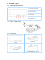
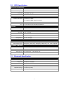
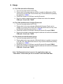
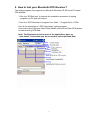
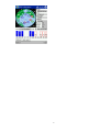
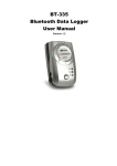
User Manual Bluetooth GPS Receiver BT-359 Ver 1.0 1 1. BT-359 at a glance 1.1 Appearance and Function 1. Bluetooth Status LED 2. GPS Status LED 3. Power LED 4. Power Button 1.2 How to change battery 1.3 Accessories Car charger BT-359 USB cable Travel charge adapter (optional) 2 2. Introduction The BT-359 is a GPS receiver with Bluetooth interface and built-in active antenna for high sensitivity to tracking signal. Based on the SiRF star III Low power chip set and supports all functions (Single Sat updates in reduced visibility, Superior urban canyon performance, FoliageLock for weak signal tracking, etc.). The BT-359 is well suited to system integrations including PDA, Smart phone, Tablet PC and Notebook PC with Bluetooth devices. It satisfies a wide variety of applications that are purposes in automotive and outdoor recreation navigation systems. 2.1 Package Before you start up, make sure that your package includes following items. If any item is missing or damaged, please contact your dealer immediately. Bluetooth GPS Receiver A CD with the User Manual and the Testing Program. AC Power Charger (optional) DC Car Power Charger 2.2 Power Switch Power on: Press the power button 1 second until the GPS status LED is on. Power off: Press the power button 1 second until the GPS status LED is off. Reset: Press the power button for 5 seconds. 2.3 LED Function Bluetooth Status LED (Blue): Blinking (Slowly) ---- Not connected to any Bluetooth device. Blinking (Quickly) ---- Connected to other Bluetooth device. GPS Status LED (Green): Blinking ---- GPS position is fixed Steady light ---- GPS position is not fixed Battery Status LED (Red/Yellow): Red ---- Battery power is critically low. Charge it immediately. Yellow ---- Battery is charging now. LED off ---- Battery is partially full or fully charged. 2.4 Power-saving Function When you start the power of the Bluetooth GPS Receiver BT-359, if the Bluetooth is not connected to any devices within 10 minutes, BT-359 will turn off the power automatically, and all the LED will go off simultaneously. 3 3. Specification 3.1 System Specification Electrical Characteristics GPS standard SiRF StarⅢ GPS Antenna Built-in ceramic patch antenna Bluetooth standard Operation range Bluetooth Default PIN Operation time Charge time Auto Shut-Off Battery Charging Bluetooth V2.0 10 meters (33 feet) 0000 Up to 11 hrs 4~5 hrs When no active Bluetooth connection has been detected within 10 minutes. Mini USB connector (not for data) POWER BUTTON Power On Pressing the Power button for approximately 1 second will cause the unit to turn ON Power Off Pressing the Power button for approximately 1 second will cause the unit to turn OFF Perform reset Pressing the ON-OFF button for approximately 5 seconds will cause the unit to reset itself. STATUS LED’S GPS status Flashing – GPS position is fixed Steady – GPS position is not fixed Power status Solid Red – Battery Low Solid Amber – Battery is being charged Bluetooth status Flashing (Slow) – Not connected to a Bluetooth device Flashing (Fast) – Connected to a Bluetooth device TEMPERATURE Operating -10°C ~ 60°C (14°F ~ 140°F) Storage -20°C ~ 70°C (-4°F ~ 158°F) Humidity Operational up to 95% non-condensing POWER DC supplies 4.5V~5.5V / 0.5A BATTERY Battery Cell Type Lithium –ion Rechargeable Battery MECHANICAL Dimension 82.0 mm x 41.0 mm x 13.4 mm 4 3.2 GPS Specification Electrical Characteristics GPS Chipset Frequency SiRF Star III L1, 1575.42 MHz C/A Code 1.023 MHz chip rate Channels 20 channel all-in-view tracking ACCURACY Position Horizontal 10 meters, 2D RMS 1-5 meters 2D RMS, WAAS corrected Velocity Time 0.1m/sec 1 micro-second synchronized to GPS time DATUM Datum Default: WGS-84 ACQUISITION RATE Hot start 1 sec., average Warm start 38 sec., average Cold start 42 sec., average Reacquisition 0.1 sec. average PROTOCOL GPS Protocol GPS Output format Default: NMEA 0183 (Secondary: SiRF binary) GGA(1sec), GSA(1sec), GSV(5sec), RMC(1sec), GLL, VTG is optional DYNAMIC CONDITION Acceleration Limit Altitude Limit 18,000 meters (60,000 feet) max. Velocity Limit 515 meters/sec. (1,000 knots) max. Jerk Limit 3.3 Less than 4g 20 m/sec**3 Bluetooth Specification Electrical Characteristics Bluetooth Chipset Frequency Standard CSR BC4 2402MHz to 2480MHz Bluetooth V2.0 Bluetooth Profile SPP (Serial Port Profile) Operation Range 10 meters (33 feet) Output Power 0 dBm (class II) 5 4. Usage 4.1. For PDA with built-in Bluetooth 1. Turn on the power switch in BT-359. 2. Please refer to the user manual of PDA to enable the Bluetooth of PDA connecting to the BT-359. Some PDAs may need the Bluetooth passkey, the passkey is “0000”. 3. Check the number of COM port used by Bluetooth. 4. Run the suitable mapping/navigation software and select the correct COM port & baud rate: 38400 4.2. For PDA with Bluetooth Compact Flash card 1. Turn on the power switch in BT-359. 2. Please refer to the user manual of Bluetooth Compact Flash card to enable it to connect with the BT-359. Some Bluetooth devices may need the Bluetooth passkey, the passkey is “0000”. 3. Check the number of COM port used by Bluetooth.(Example COM 6). 4. Running the suitable mapping/navigation software and select the correct COM port & baud rate: 38400. 4.3. For Notebook with Bluetooth device 1. Turn on the power switch in BT-359. 2. Please refer to the user manual of Bluetooth device to enable it connects to the BT-359. Some Bluetooth devices may need the Bluetooth passkey, the passkey is “0000”. 3. Check the number of COM port used by Bluetooth.(Example COM 6). 4. Running the suitable mapping/navigation software and select the correct COM port & baud rate: 38400. Note: The Bluetooth device in most of the applications have an “auto-detect” feature that you do not need to select the Baud Rate. 6 5. How to test your Bluetooth GPS Receiver? The testing program only supports the Microsoft Windows CE & Pocket PC based PDA platform. 1. Run the “GPSinfo.exe” to execute the installation procedure of testing program (via PC and ActiveSync). 2. Run the “GPS Information” program from “Start → Program files” of PDA. Here is the description of “GPS Information” testing program: User must select COM port, Baud Rate (38400) and click the [Star GPS] button to start receiving GPS data. Note: The Bluetooth device in most of the applications have an “auto-detect” feature that you do not need to select the Baud Rate. 7 8 6. Troubleshooting Bluetooth is unable to connect A) Check if the GPS Bluetooth indicator is flashing normally. That is, flash one per each three second means the product is under standby mode; flash once per second means Bluetooth has been online already. B) Check if energy level is sufficient. If red LED is lid up, then the battery level is insufficient, please recharge it until the red indicator is off (recharge is complete). GPS cannot be positioned A) Check if GPS indicator operates normally or not. If the indicator is constantly lid up, it means that GPS is in operation; if the indicator is flashing, it means GPS is positioned already. B) If GPS cannot be positioned for long, apply GPS info software to make a Cold Start first, and then move to an open space performing the positioning task. Check if power level is sufficient. If the red LED lights up, it means the power is insufficient, please recharge it until the red indicator is off (recharge is complete). 7. FAQ z z I am not getting GPS data into my application on my Windows PC. 1. Check your DEVICE MANAGER to confirm the COM Port number assigned to the GPS. Then be sure this is the same COM port number configured in your application. 2. Be sure your Baud rate is configured correctly at: Baud Rate: 38400 Data bit: 8 Parity: None Stop Bit: 1 Flow Control: None 3. Configure the GPS Info utility with the correct COM Port and test your GPS receiver first before using it in your application. Will the GPS work with other Street Mapping software? Globalsat GPS receivers provide standard NMEA data for mapping software to use and convert to coordinates and should work well with most any NMEA compliant software on the market today. z How accurate is the GPS? The USB GPS is WAAS/EGNOS capable, and for units sold in North America through authorized resellers, these units are WAAS/EGNOS enabled unless otherwise stated. Accuracy can be up to 5 meters 2D RMS with WAAS enabled and 10-15 meters 2D RMS WAAS disabled 9 z What is ideal GPS environment? The GPS requires an open, clear view of the sky. Buildings, covered parking areas, tunnels and dense foliage can cause the GPS receiver to be unable to get a location fix. If you are parked in a covered parking lot or near a tall building, it is recommended that you drive away until you have a clear view of the sky before using the GPS receiver. You may need to give the GPS a few minutes to find or get a fix its location. z How do I know if the GPS is ON? If your PC is on and the COM port was configured properly, the GPS receiver is on and receiving the streaming GPS data. This can be verified by opening your mapping software program. In addition, the Globalsat GPS has a built-in LED status indicator that shows the following: LED OFF: GPS receiver is off (no power). LED ON (solid): No fix, searching for GPS signals. LED FLASHING: Position fix established and GPS signals are being received. z Why does the GPS not work near buildings and other tall objects? The GPS uses satellites in the space to find out where it is. Therefore it needs a clear view of the sky. Tall buildings and other objects that block the receiver’s view to the sky make it infeasible to determine your location. Sometimes the satellites are not overhead but near the horizon. In these cases the GPS must have a clear view of the horizon. z Other Comments Please allow an adequate amount of time for the GPS receiver’s boot-up (TTF) to complete before contacting Technical Support. FCC Notices This device complies with part 15 of the FCC rules. Operation is subject to the following two conditions: (1) This device may not cause harmful interference, and (2) This device must accept any interference received, including interference that may cause undesired operation. FCC RF Exposure requirements: This device and its antenna(s) must not be co-located or operation in conjunction with any other antenna or transmitter. NOTE: THE MANUFACTURER IS NOT RESPONSIBLE FOR ANY RADIO OR TV INTERFERENCE CAUSED BY UNAUTHORIZED MODIFICATIONS TO THIS EQUIPMENT. SUCH MODIFICATIONS COULD VOID THE USER'S AUTHORITY TO OPERATE THE EQUIPMENT. 10