1
Aristel Networks Pty Ltd
USER MANUAL
OAM program for Brigate g3
User Manual
CONTENT
1. GENERAL DESCRIPTION
1.1. Installing the program
1.2. Menu description
1.3. Icons description
1.4. Tree options
1.5. Language option
1.6. Status bar
1.7. Display issues
1.9. Password protected mode
1.10 Details about installing the OAM application
2. CONNECT...
2.1. Connecting steps
2.2 "Connect To Modify..." and "Connect To View..."
2.3. "Modify Configuration" and "Viewing Configuration"
2.4. Programming Area
2.4.4. Routing Table
2.5. "UMTS & SMS Analysis..."
2.6. "Loading Image File"
3. Print options
4. SYSTEMS
4.1. Add
4.2. Remove
5. FACILITIES
5.1. Font
5.2. Colors signification
5.3. View print files
5.4. LOG FILES
6. TREE COMMANDS
6.1. Modify parameters
6.2 LAST CONFIGURATION
6.3 HELP
7. GLOSSARY
2
3
3
5
6
7
8
9
10
11
14
15
15
16
18
20
30
44
60
64
65
65
66
67
67
68
69
69
70
70
71
72
75
OAM program for Brigate g3
User Manual
OAM program for Brigate g3
(Operation, Administration and Maintenance)
1. GENERAL DESCRIPTION
1.1. Installing the program
This OAM program is intended for the configuration and
administration of the BRIGATE G3 equipment via serial port.
Also, the program allows you to send and receive SMS messages
from the computer that is connected to the equipment or to perform
SMS to e-mail and e-mail to SMS automated conversions.
The serial connection is made by means the special serial cable
(supplied in the BRIGATE G3 package).
This cable features a RJ-11 connector for connection to the
BRIGATE G3 unit and a standard DB-9 connector for the COM port
of the desktop PC or notebook computer you use to configure and
administrate the equipment.
The installation CD / diskette supplied with the equipment, includes
the OAM (Operation, Administration, and Maintenance) software.
The isdncfg.exe program is a self-contained Win 32 executable
and may run on any desktop PC or laptop that fulfils the following
minimal requirements:
- Operating system: Windows 95 or later versions
- Minimum processor 486
- Recommended minimum 500 MB free space on HDD
- Minimum 32 MB of RAM
- One serial port free (available)
- Graphics resolution 1024 by 768 pixels - colors High Color (16bit)
or True Color (32bit)
3
OAM program for Brigate g3
User Manual
To install the program on a desktop PC or a laptop, insert the
diskette or CD into the respective disk drive unit and copy the
structure of folders and files to your hard disk drive.
Then run the file isdncfg.exe from the directory on your hard disk.
The program includes an on-line help (in English).
The names of the windows, menus and icons can be displayed in
several languages.
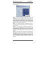
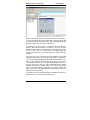
1.2. Structure of the graphic interface
The screen of the OAM program for Brigate g3 includes several
elements: Title bar, Menu Bar, Toolbar (a set of buttons with icons),
tree commands (Connect, Lading, Parameters) and different
„Programming Area” or „Info” screens (for SMS, for UMTS
modules, for the TE or NT interfaces).
All these elements of the isdncfg.exe program will be thoroughly
described in the paragraphs that follow.
Then, concluding the first chapter, you will see a paragraph
detailing issues of the program’s installation.
4
OAM program for Brigate g3
User Manual
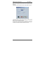
1.2. Menu description
The menu bar is the fist on top of the screen, just below the title bar
that shows “ISDN-2-UMTS Ver. 3.4.1” OAM” or upper version
within 3.4.
Menu items are: Systems, Facilities, About, Help and Exit.
Systems
- Add
Adds a BRIGATE G3 system in the tree-like
structure
- Remove
Removes a system from the structure
Facilities
- Font
Chooses the font type for the text in the
windows that are displaying configuration:
- "Modify Configuration"
- "Viewing Configuration"
- "Analyzing UMTS modules"
- "Last Configuration".
Each of those windows is corresponding to a
selection over a tree command: "Connect To
Modify...", "Connect To View...", "UMTS
Analysis..." and "Last configuration";
Shows the significance of colors used in the
windows that are displaying configuration. The
- Color signification colors are used in the representation of the
3G/3G modules, NT and TE interfaces. The
user is allowed to modify the colors as he likes.
- View print files
Opens a window in which you may see the text
files in which other text files or data information
have been printed using the button "Print" (or
icon "Print").
About
Shows the version of OAM software
Help
Opens up the window with the help files for the
program
Exit
Exit from the OAM program
o
5
OAM program for Brigate g3
User Manual
1.3. Icons description
The toolbar with button icons is located below the Menu. Some
buttons are equivalent to options from the Menu or from System.
Definition of the button icons:
Icon
Name /
Equivalent to
Significance
System > Add
Adds a BRIGATE G3 system in the
tree-like structure
System >
Eliminate
Removes a BRIGATE G3 system from
the structure
Print
Prints the files, to the printer or in a text
file
Find
Defines text for find
Find next
Finds next appearance
Configuration list
Lists the configuration of device
Saving current
configuration
(works only in connected state - option
"Connect To Modify...")
Loading
configuration
(works only in connected state - option
"Connect To Modify...")
Password mode
Starts / stops password working mode
Users
Allows definition of users for OAM
software "isdncfg"
About from the
menu
Info about program
Help from the
menu
Help file
Exit from the
menu
Exits the program
The toolbar with button icons is dynamic, its aspect changes
according to actions performed by the user. If a system is
connected you will see some icons, if no BRIGATE G3 is
connected you will see a different set of icons. When you use a
„Connect to View” link, you are not allowed to perform changes, so
the „Modify” icons are not available.
6
OAM program for Brigate g3
User Manual
Finally, if no BRIGATE G3 equipment is connected, the „Password”
and „Login” icons are visible – when you are already connected to
a system, you no longer need those two icon options.
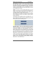
The OAM toolbar software can look like this:
A BRIGATE G3 system is connected
Viewing files for a system
None of the above situations
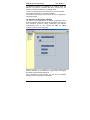
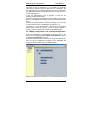
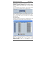
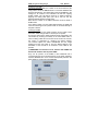
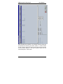
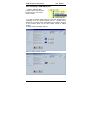
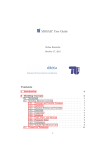
1.4. Tree options
The OAM application for BRIGATE G3 makes use of a tree-like
(branching) structure to launch actions over the selected BRIGATE
G3 interface. As you see in the image below, the „tree” for each
BRIGATE G3 system has several „branches”, which are the
commands: Connect To …, Loading, Disconnect, Parameters and
so on.
Through the OAM program you can
configure and manage maximum 20
different BRIGATE G3 devices. Here
you may see a unit called “Vega1”
and another “Vega2”. Each of these
has associated a directory folder (in
the same location with the
executable
application
"isdncfg.exe") and a subdirectory for
the log and authentication files.
All systems can be sequentially
accessed via serial cable in order to
be configured and maintained (of
course, you may connect to only
one BRIGATE G3 equipment at a
time).
The OAM program sees the Brigate
g3 systems in a tree-like structure,
where every equipment has its own
„branches”. You can perform
settings upon the first (default)
configuration
or
save
a
configuration and then load it on the
next Brigate g3 system , etc.
7
OAM program for Brigate g3
User Manual
1.4.1. Description of the tree structure
cfg_
Significance
Connect To
Modify...
Initiates a connection to the selected Brigate
g3 system in order to download system
configuration and perform changes over it;
Connect To
View...
Initiates a connection to the selected ISDN-toUMTS system in order to download the
system configuration and view it;
UMTS & SMS
Analysis...
Initiates a connection to the selected
BRIGATE G3 system and allows the analysis
of UMTS modules. Allows you to send and
receive SMS messages from the computer;
Loading Image
File
Initiates a connection to the equipment and
allows the loading of a new software image
into that system;
Disconnect
Disconnect the connection to the system if
this connection was on; it is used to terminate
the connection in each of the four cases
shown above;
Parameters
Displays the parameters of the connection to
the BRIGATE G3 system;
Last
configuration
Displays the configuration received at the
time of latest status inquiry to the system;
Log
Displays the log and lch files;
1.5. Language option
On the bar with the icon buttons, in the upper right corner of the
screen, there is also a listbox (
) which allows you to
change the language that is used in all menus, dialog boxes,
windows and messages of the program. The default language is
English, shown by the corresponding flag. You may select English,
French or Romanian:
- English language
- Romanian language
- French ma
8
OAM program for Brigate g3
User Manual
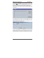
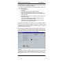
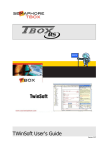
1.6. Status bar
The status bar is divided into seven columns.
The first three columns (starting from the left side) display
indicators for supervising a connection.
These three fields are filled only in a state of connection between
the "isdncfg" software and a BRIGATE G3 unit.
A state of connection (between the OAM software and the
BRIGATE G3 system) can occur if one of the following three
options is selected:
-"Connect To Modify..." or "Connect To View...",
- "UMTS Analysis..."
- "Loading Image File".
First column "
" indicates the
number of commands that will be sent to the system. Every
modification (changes of system configuration) or data request that
is performed on the system is translated into commands. Those
commands are sent to the BRIGATE G3 equipment; the second
and the third columns show protocol messages. The protocol is
implemented between "isdncfg" software running on the PC and the
BRIGATE G3 system that connected to it.
The second column contains messages which begin with character
">" and corresponds to the messages sent from the OAM software
to the BRIGATE G3 system.
The third column contains messages which begin with character "<"
and corresponds to the messages received by the OAM software
from the BRIGATE G3 system.
In the example, image of status bar, the text is "Read CLIP Record
49" which corresponds to the reading of the record number 49 from
the CLIP table);
The fourth column displays the date and time of the computer
system where isdncfg program is running.
Date format is dd-mm-yyyy hh-mm-ss (
);
The fifth column is used to indicate the length of the SMS2MAIL
queue (the queue accepts maximum 1.000 messages);
The sixth column is used to indicate the length of the MAIL2SMS
queue (the queue accepts maximum 1.000 messages);
The seventh and rightmost column is a color indicator for the
connection: light blue when the OAM program is connected to a
BRIGATE G3unit (
to a system (
) or red if the program is NOT connected
).
9
OAM program for Brigate g3
User Manual
1.7. Display issues
The panel located to right side of the tree window is used by two
different types of windows.
First type of window is used for displaying the configuration of the
BRIGATE G3 system, in the commands: "Modify Configuration",
"Viewing Configuration", "Analyzing UMTS modules" and
"Last Configuration". In those windows the right mouse button is
used as follows:
- for the windows "Modify Configuration", "Viewing
Configuration" and "Analyzing UMTS modules" the serial port is
opened. If you click the right mouse button over the status bar, a
message ("Do you wish to disconnect?") will be displayed, asking
you if you want to disconnect the connection to Brigate g3.
- for the second case, when "Last Configuration" window is
displayed, the right mouse button is used to hide the window. The
confirmation message asks you: "Do you wish to hide last
configuration?".
All those windows include in the title bar the name of the
connected/viewed BRIGATE G3 system. For windows "Modify
Configuration”, “Viewing Configuration" and "Analyzing UMTS
modules", only a click upon the tree command called "Disconnect"
for the Aristel system that is connected or viewed will caused the
disconnection of the link between OAM and the connected system
for the windows. In second case, the same "Disconnect" command
will cause the display of the "Do you wish to hide configuration?"
message.
The second kind of window is the one used to display the log files
as a result of an action over the "Log" tree option. In this situation
the title of the window includes the words "Local Viewer" and the
system name. A right-click with the mouse will cause the message
"Do you wish to hide?" to be displayed.
The content of that second window can be updated with other data
simply by selecting another option from the tree structure.
Note1): if any of the following commands: "Connect To Modify...",
"Connect To View...", "UMTS Analysis..." and "Last configuration" is
used while "Local Viewer" window is displayed, then the "Local
Viewer" window will be hidden.
Note2): if "Local Viewer" command is used while any kind of
window from the first type presented is displayed, then the "Local
Viewer" window will be displayed over the other window. The user
must hide (using the right mouse button) the "Local Viewer" window
to see again the window which was displayed before.
10
OAM program for Brigate g3
User Manual
1.8. Files
The ISDNCFG program uses several types of files: for events, for
saving current configuration (your settings), system software image
file (application software to be sent to a BRIGATE G3 unit), etc.
The log files are saved in the "Log" subdirectory for each BRIGATE
G3 system: they contain the moments of time for the connections to
the system, the configuration read from the system and any
modification performed on that configuration.
The configuration of a BRIGATE G3 system can be downloaded
and saved in a file named by the user. The file will have extension
"cfg" and will be located in the "CONFIG" directory, in the same
place where the program "isdncfg.exe" is located. After you save
the configuration of one BRIGATE G3 system you can load it into
several other Aristel systems.
The software image file has "hex" extension. It is a downloadable
image of the software application that runs on the BRIGATE G3
equipment. Such kind of file can be located anywhere on the Hard
Disk. The user will open the file from a dialog window and the
software image will be send into the respective BRIGATE G3
system.
1.9. Password protected mode
The "isdncfg" software includes a multiple (hierarchical) password
protection implementation.
Password protection mode is useful when several users are
working with "isdncfg" software and certain actions on BRIGATE
G3 system(s) must be performed carefully. According to the
hierarchy, different users may have different rights. The
implementation assumes that one user is the administrator of the
"isdncfg" software and the first step is to create such a privileged
user.
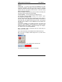
The icons that refer to the password mode of operation are the
. By default, the OAM application displays the
following:
first and second icon as being inhibited (not active). After you
define the administrator you will be allowed access to the first icon
(" ").
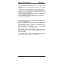
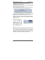
If you go to password
protected mode
without first defining of
an administrator, it
won't work and the
following error
message will show up:
11
OAM program for Brigate g3
User Manual
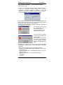
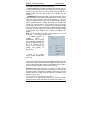
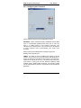
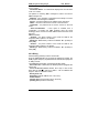
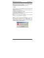
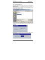
For defining an administrator you must choose the option "User
definition" (" "). You enter the default password "Aristel" in the
access password window, the next image will appear to show you
that you must enter the identification data for the administrator.
After pressing the "OK" button to confirm you will be asked to type
user settings:
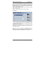
At the beginning the list is empty, you must first add an user to the
list by selecting the "Add" button to the right. Afterwards, you may
delete or edit the already existing users:
In case of the definition for the administrator, the two boxes for
possible rights are already selected: "Changes allowed" and "Load
a New Image allowed", because the administrator has all the rights.
12
OAM program for Brigate g3
User Manual
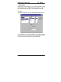
For each new user two fields must be always filled: "Name" and
associated "Password".
An additional window is used to confirm name and password.
Only the administrator can perform actions over definition of users.
He can add, edit and delete other users. There is a restriction that
specifies that the administrator cannot be deleted.
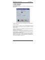
Once the definition of an administrator is done, the subsequent
access to the icon "Users definition" (" ") will require administrator
name and password:
Also, when you selected the icon option "Password mode" (" "),
the administrator name and password is required. Operation in
Protected mode is indicated on the title bar of the "isdncfg" software
by the words "protected mode" at the end.
When the protected mode is launched, then a second click on the
icon "Password mode" will end this mode.
After protected mode is started, then all access (connections) to the
BRIGATE G3 system(s) will be protected by additionally requiring
user identifications as follows:
- for command "Connect To Modify..." - the user name and
password are requested. The user must have the right to perform
changes on system configuration ("Changes allowed"). If the user
or password are wrong then the "Incorrect identification" message
will be displayed. If the user hasn't the right to change configuration
then the message "Operation not allowed" will be shown.
- for command "Connect To View..." - the user name and
password are requested. It is not necessary for the user to have
any right. If the user or password are wrong then the "Incorrect
identification" message will be displayed.
- for command "UMTS & SMS Analysis..." - the user name and
password are requested. It is necessary for the user to have the
right to perform changes on system configuration ("Changes
allowed").
13
OAM program for Brigate g3
User Manual
If the user or password are wrong then the "Incorrect identification"
message will be displayed. If the user hasn't the permission to
change configuration then the message "Operation not allowed" will
be shown.
- for command "Loading Image File" - the user name and
password are requested. The user must have the right to load new
image file on the system ("Load a New Image allowed"). If the user
or password are not correct then the "Incorrect identification"
message will be displayed. If the user hasn't the right to load a new
image then the message "Operation not allowed" will be shown.
1.10 Details about installing the OAM application
Before establishing a first connection to BRIGATE G3 first you must
check that the serial cable for programming is connected to the
corresponding COM port of your computer.
To start, you must add a BRIGATE G3 interface to the tree-like
structure of connections, since in the beginning there is no
equipment connected.
Select the options Systems->Add. To ensure communication with
the respective BRIGATE G3 interface, in the field “Serial
Parameters” you must select the number of the serial port where
the equipment is connected.
Before you achieve the first connection to a BRIGATE G3 system,
you should decide whether to use or not the password protected
(hierarchical) mode of operation, which is shown in chapter 2.8.
If you decide NOT to use the password mode, then you can go
directly to the achievement of a connection to the respective
Brigate g3 system.
There are three basic types of options for connection, respectively:
- Connecting for changes or viewing the configuration (chapter
2.2)
- Loading a new software image (chapter 5)
- Settings related to the analysis of the UMTS/UMTS modules and
of the SIM cards (IMSI codes and the operator where the SIM is
registered - chapter 3), or sending / receiving SMS messages. All
these options are valid only if the BRIGATE G3 equipment has
inserted a SIM card that is registered to the 3G/3G mobile
network.
If you decide to use the password-protected mode, then you must
follow the procedure described in chapter 1.9, that is:
– Define an administrator, then add one or several users
– Go to the password-protected mode of operation
– Quit (exit from) the OAM application
– From now on, when you start again the OAM application, the
password protected mode of work is active, so you may go on to
connect to a BRIGATE G3 interface.
14
OAM program for Brigate g3
User Manual
2. CONNECT...
2.1. Connecting steps
There are four kinds of connections to a BRIGATE G3system:
(a)- "Connect To Modify..."
(b)- "Connect To View..."
(c)- "UMTS & SMS Analysis..."
(d)- "Loading Image File"
Both options (a) and (b) allow the user to connect to the BRIGATE
G3 system and download the configuration.
Option (a) the downloading of the configuration data is protected by
a password. If the password is recognize by the equipment, the
downloading process is started. The user will be able to perform
changes over the configuration.
Option (b) situation the password will be not requested and the
configuration will only be readable (you can’t modify it).
Option (c) is used without a password request and implies only
actions that can be done over the UMTS/GPRS modules.
Option (d) allows the user to load a new image file (a new software)
into the BRIGATE G3 system. See later on details about loading a
new image file. See also the important notices related to loading
a new version of the application software to the BRIGATE G3
equipment!
Once the password is recognized by the BRIGATE G3 interface as a result of a connection started by the options a) or d) - the
password will no longer be requested from the user. From now on
the password is automatically filled by the OAM application.
15
OAM program for Brigate g3
User Manual
2.2 "Connect To Modify..." and "Connect To View..."
(case a) and case b))
First click on the respective "Connect" action you want to perform.
In case of a connection to make changes over the system
configuration (command "Connect To Modify..."), when the
connection is successfully established a dialog window will appear.
The login procedure on the remote equipment will follow:
By pressing the <ENTER> key the user will validate password and
close the "Login Window". The user can abort the login procedure
by typing the <ESC> key in the "Login Window".
In case of unsuccessfully login (password mismatch), the password
will be asked one more time.
The message which shows
the unsuccessful login is
"Authentication failed".
The "Login Window" will be
displayed one more time.
The total number of attempts
to login into the BRIGATE G3
system is four.
If the total number of attempts
is exceeded, the user will see
an error message indication
"Passing Authentication Retry
Error"
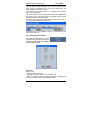
A dialog box will appear and in case of connection successfully
established the OAM program tries to download the configuration
information.
There are seven configuration files to be loaded, as follows:
- settings of the 3G/3G mobile modules ("Category Info", “PIN Info”
and "Target Info");
- directions allocation (both on UMTS/GPRS modules and on TE "Directions Info");
- settings for TE and NT connections ("ISDN Category");
- routing table
- CLIP table
16
OAM program for Brigate g3
User Manual
For each of these data files there is a progress indicator, as shown
in the next image:
Note1: The OAM program communicates with the connected
ISDN3UMTS system by sending and receiving messages. Each
message send from the OAM software must be confirmed by the
system. If the confirmation message is not received, then the OAM
software resends the last sent message. There is a total number of
four retries that can occur, after which an error message will be
displayed: "Passing Connection Retry Error".
Note2: If you are already connected to one BRIGATE G3 system,
you cannot connect to a different system; you must first disconnect
from the first one.
Note 3: If you are connected to a BRIGATE G3 system with one
option and you select another of the four connecting options, the
OAM software performs an automated "Disconnect" command. The
OAM application first disconnects form the current connection
option then connects again, using the connection option you have
selected.
Note 4: The „Password” window mentioned above is displayed only
the FIRST time you connect to the system or in case of successive
authentication errors. Such errors can occur, for instance, when
you switch (interchange) the devices. Suppose you have at least
two connections with two different Aristel BRIGATE G3 devices that
may be connected to the same PC, and each has its own
password.
17
OAM program for Brigate g3
User Manual
Normally, you use connection 1 for the equipment 1, and
connection 2 with the equipment 2. If by mistake you physically
switch the two devices (you place equipment 2 on connection1, but
this equipment needs a different password from the one stored by
the OAM application for the respective position) an error will occur.
This is what happens:
i) first, the authentication error is signaled, you will see the
message "Authentication failed"
ii) then the OAM program attempts up to four times to connect, then
gives up and displays the message "Passing Authentication Retry
Error"
ii) finally, the Password window shows up, allowing you to enter the
correct password for the new BRIGATE G3 system (no 2)
iv) further on, if you keep the correct connections, the "Password"
window doesn’t show up anymore, you are no longer required to
enter the password, because it is stored by the OAM program.
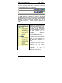
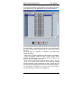
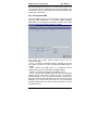
2.3. "Modify Configuration" and "Viewing Configuration"
Once the configuration is downloaded, in the right pane of the
window will be displayed either "Modify Configuration" (case a)
or "Viewing Configuration" (case b).
By means of these windows, the user can change and respectively
view the current configuration (settings) of the BRIGATE G3
equipment which is connected to the OAM computer.
18
OAM program for Brigate g3
User Manual
In the previous image you should notice:
- on top, a title bar showing the version of the OAM program
running on your PC, such as Ver. 3.4.12
- a menu bar with the names "Systems", "Facilities", "About", "Help"
and "Exit";
- underneath it, a toolbar with different buttons marked with icons;
- to the left, the tree-like structure of installed BRIGATE G3
interfaces (one or several Aristel equipments that may be
connected to the OAM program);
- the right panel, blue, which is the main window, with title Modify
(of View) Configuration System 0 name …;
- the flag indicating the language used for displaying information;
- at the bottom, the status bar
The blue configuration pane of the OAM window displays a zone
called “Programming Area”.
Here you can program (establish the settings) the BRIGATE G3
unit.
In the Programming Area are shown the two UMTS ports and
respectively the NT and TE interfaces.
Also in this area you can select "Routing", "CLIP UMTS",
“Directions and Timers” or "Password" options.
With "Routing" option you can operate modifications over the
routing table, with "CLIP UMTS" option you perform modifications
over the CLIP table.
The "Password" option is used to change the password used to
connect to a BRIGATE G3 system for modifications.
19
OAM program for Brigate g3
User Manual
2.4. Programming Area
In the Programming area you see a graphic representation of the
BRIGATE G3 equipment, featuring:
- the two UMTS modules (numbered UMTS0 and UMTS1)
- the TE and NT interfaces of the equipment.
There are also zones with names "Routing", “Directions Timers”,
“Password” and "CLIP UMTS" used for editing the "Routing Table"
and respectively the "CLIP UMTS table", overflow directions and
timers, and the Password option.
With “Directions/Timers” you may establish the first and second
directions for overflow and the two timer values, used for sending
the UMTS call and respectively for the callback feature.
Firmware version
The bottom right corner of the Programming Area shows the
current version of the firmware application running on BRIGATE G3
written with white letters on blue background.
In the above example you may see “
” meaning
that the application running on BRIGATE G3 is version 3.0 and the
processor type is “128”.
The digits following the underscore character are a code for the
processor of the BRIGATE G3 unit. There are two types of
processors, coded as _64 and respectively_128.
20
OAM program for Brigate g3
User Manual
This is important when you perform a firmware update (Tree option
“Loading image file”): you must check that you load the type of
firmware image that is adequate for your equipment. If your
equipment has a processor type “_128”, you must upload only
image files of that kind, for instance with name
“isdngs_si_30_128_c.hex”.
If you have an older equipment, which does not show the
Processor Type, but only the version, such as “isdnUMTS1.9”, you
should upload only image files of the type “_64”.
Each port of the Brigate g3 equipment (UMTS0, UMTS1, NT and
TE interfaces) may be individually configured by clicking on the
corresponding rectangle.
Color indication
In the “Programming Area”, the 3G modules of the equipment are
shown with different colors, depending upon their current status.
Dark blue indicates an inactive module, red shows a module in the
initialization phase, light blue is for a module that has successfully
registered with the UMTS mobile network, and so on.
For instance:
this means the first module, UMTS0, is already registered, while
the second module, UMTS1, is still in the initialization phase.
Now the second module is OFF while the first is in the initialization
phase.
In this case, the first module has successfully registered with the
respective mobile network, while the second mobile module is OFF.
The second module (white color) is searching for network.
In the following paragraphs you will see a description of settings for
the 3G modules and NT and TE interfaces, for the Routing table,
etc, a few examples of ISDN-2-UMTS working modes (connections
to the PBX) will be explained.
21
OAM program for Brigate g3
User Manual
2.4.1. Configuring a 3G module
To configure a UMTS module (0 or 1) click on it and the “UMTS
Settings” window shows up, allowing you to specify the operating
parameters for the respective UMTS module:
Depending of the selected 3G/3G module the title of the window
will be "UMTS Settings Port 0" for the first 3G/3G module and
"UMTS Settings Port 1" for the second UMTS module.
Installed - when this option is enabled, it allows the activation of
the port;
IN - input, port used only for incoming calls; if this option is disabled
then no incoming call will be accepted from the 3G/3G network on
this module;
If this option is disabled, the incoming calls will be rejected!
OUT - output, the port will be used for outgoing calls;
CLIR - if this option is checked then identity of the call will not be
sent (identity restricted);
The next two options DISA and OPERATOR are used for directing
incoming calls from the 3G/3G network. The option DISA and
OPERATOR are mutually exclusive, only one of them can be
enabled by the user at a moment time.
22
OAM program for Brigate g3
User Manual
The mode of usage for the options is as follows:
- if either OPERATOR or DISA checkboxes are enabled, that is a
wrong situation because no method to deal with the incoming call is
defined. If the user does not want to allow incoming calls on a
2G/3G module, then the best method is to disable the "IN"
checkbox.
- if OPERATOR checkbox is enabled, as shown previously, the call
will be forwarded to the PABX port through the NT or TE interface.
Then the operator decides which local extension to call. The
interface is specified in the "Type" field. An ISDN SETUP message
will be generated with the number specified in the "Target" field
through the selected interface. The maximum size for the target
field is 4 digits. If you type "---" characters you can specify an empty
target (no number). In such a situation the ISDN-SETUP message
will contain an empty called party number and the call will be routed
to the operator of the PABX (if such a setting is validated in the
PABX).
Note: the "Target" field can contain only digits from "0" to "9" and
characters "---" to indicate an empty value.
- if DISA checkbox is
enabled
instead
of
OPERATOR, the incoming
call will also be forwarded to a
port of the PABX through the
NT or TE interface, but the
aspect of the window for
settings will change, as
shown here:
Instead of the “Target”
field, a “number of digits” field
shows up.
The incoming call will be answered by the BRIGATE G3 device and
a DISA tone will be provided to the calling party. On this tonality the
caller can dial (using DTMF codes) a local extension of the PBX or
an external number to get out of the phone exchange.
Important! When DISA checkbox is selected, the field “Target”
becomes “Nr. Of Digits” and instead of the target, it represents the
maximum number of digits that are waited to come from the 3G/3G
network. When this number is reached, the call is forwarded, even
if digits are still coming.
You may specify at most 20 digits in this field.
If you enter “0” no digits will be waited for. This means the ISDNSETUP message will be sent without any called party number in it.
23
OAM program for Brigate g3
User Manual
AOC – Abbreviation from “Advice of Charge”, a signaling protocol
used to send charge (billing) pulses to the PBX where BRIGATE
G3 is connected. AOC is the charge for the call, computed by the
UMTS terminal and expressed in terms of Home Units. The charge
pulses are sent at the beginning of the call and during the call,
according to two elements that you may program at the bottom of
the window. The two items are the number of initial pulses
("Number of pulses at response") and the time delay between
two billing pulses ("Pulse generating period").
If the option "Audio Billing Pulse Warning" is set the billing pulses
can produce an audio (sound) confirmation at the calling party.
Data capability –provides the equipment with data capabilities.
Depending upon the type of mobile modules of Brigate, you may
use the respective module as a mobile modem.
If the checkbox is marked, after an AT command the UMTS module
may be used as a wireless modem. You may use it for GPRS, CSD
(circuit switched data) or digital fax.
Direction - the “direction” or trunk group to which the port belongs.
There are four possible directions: 0, 1, 2 and 3. To the first three
values you may assigned names, such as the names of mobile
carriers (Orange, Vodafone). The names of the directions are
established in the “Directions Timers” section of the OAM program.
The fourth direction cannot be renamed, since it is not a real one, it
is used to forbid access to certain prefixes.
Pin Code - the PIN Code used by the system as PIN code of the
selected 3G/3G module.
This value is used in the situation that the PIN code is required by
the SIM card.
The length of the field "Pin Code" must be 4 digits, with individual
values between '0' and '9'.
24
OAM program for Brigate g3
User Manual
2.4.2. Configuring the TE Interface
To configure the ISDN-TE interface, click on the TE representation
in the "Programming Area" and the windows with the port settings
will appear, as shown:
TE - if it is enabled, that this is a TE-type ISDN interface;
SYNC - this option specifies that the TE interface will be used only
for synchronization from the public network. (See chapter about
“Modes of Connection of Brigate g3” for details about connecting
several units and synchronizing them).
Note: Only one of the options "TE" or "SYNC" can be selected at
the same time;
DISA - this option is used in case of incoming calls on TE ISDN
interface. The TE interface of Brigate device is connected to the NT
interface of a PABX exchange. The NT interface of the PABX is a
local interface, so the TE interface will be called with the number of
a local extension of the PABX. The Brigate system will answer to
the call and give a DISA tone, allowing the calling party to dial
numbers through DTMF tones. Then the called number will go on in
the routing table analysis.
25
OAM program for Brigate g3
User Manual
Pass Through - this option is used in case of incoming calls from
the Public ISDN network on the TE ISDN interface (situation
presented in the case 3 in the subchapter 2.3.8.). In this situation
the call will be forwarded transparently to the PABX, it just passes
through the Aristel Brigate g3 unit. The BRIGATE G3 unit is
inserted transparently between the ISDN public telephony network
and the ISDN phone exchange.
TRACE - this option is used for enabling trace facility on the TE
interface. On the HDD of the computer where OAM application is
running, a log file will be created, with the name given by the
current day. Format of the log file is dd-mm-yy.log.
The Tracing action is running until the first disconnect between
OAM software and the Brigate g3 equipment. Later, the log files
can be analyzed by means of the Ethereal “Network protocol
analyzer” application.
The indication of trace enabling is shown on the OAM screen. For
the TE interface the indication will be the "TRACE-TE" text, which
will be displayed with white letters in the bottom left side of the
system panel, as shown in the image below:
Connection Type – refers to the ISDN connection. You should
select this according to the type of the equipment (digital PBX or
telephone) that Brigate g3 is connected to. Available options are
“Point-to-point” (default) and “Point-to-Multipoint”. The Point-toPoint is used to connect only two devices, and it uses the DDI
service (Direct Dialing In). You should use this in the most usual
case, when Brigate g3 is connected to an ISDN phone exchange.
But when you have the Brigate g3 unit connected to one or several
ISDN phones or modem, you can no longer use the Point-to-Point.
Instead, you must use the option “Point-to-Multipoint”, which allows
you to connect several ISDN equipments (form two up to eight).
Instead of DDI, it uses the MSN service (Multiple Subscriber
Number). The “Point-to-Multipoint” connection should be used for
ISDN phones or other ISDN terminals.
26
OAM program for Brigate g3
User Manual
TEI Management – establishes the administration of TEI.
“Terminal Equipment Identification” is an internal ISDN
identification of connected phones.
Allowed values are “0” or “auto”, and this is related to the previous
setting – the type of ISDN connection.
For the default point-to-point connection, a value of “zero” must be
used for TEI. (It can be changed only in exceptional cases.)
If you select “Point-to-multipoint” as connection type, TEI
Management field automatically switches to “Auto”, which is the
value that must be used for the point-to-multipoint connection.
Direction - the direction to which the port is belonging. There are
four possible directions, out of which only three are active: UMTS1,
UMTS2 and PSTN.
Forward – call forwarding.
If you enter a mobile phone
number in this field, the
incoming calls (from the
PSTN network) will be routed
through the UMTS module
and
forwarded
to
the
respective mobile number).
Warning: after performing changes to the TE interface you should
reset the equipment if you want your settings to be valid. The new
values for the parameters will be enabled only after a RESET. To
perform a reset of the ISDN-2-UMTS unit, pull out the power supply
jack. Wait at least ten seconds, then plug the jack back in. The
BRIGATE G3 will start working with the new parameters.
27
OAM program for Brigate g3
User Manual
2.4.3. Configuring the NT Interface
The NT interface has just a few programmable functions:
PH-DISACT - When checked this setting establishes that the ISDN
Layer 1 is deactivated (disabled) when there are no calls. The
Layer 1 of ISDN protocol is the Physical connection. The
inactivation of the physical layer or the connection may be required
in some instances when synchronization error could occur
otherwise.
Please note that not all ISDN phone exchanges support the
disabling of the physical layer!
TRACE - this option is used for enabling trace facility on the NT
interface. On the HDD of the computer where OAM application is
running is creating a log file with the name given by the current day.
Format of the log file is dd-mm-yy. log (format day-month-year).
Trace action is running until the first disconnect between OAM
software and the ISDN-2-UMTS equipment. The log files created
can be analyzed later by means of a program such as the Ethereal
application.
28
OAM program for Brigate g3
User Manual
The indication of trace enabling is presented on OAM panel. For
NT interface the indication will be the "TRACE-NT" text
(
panel.
), which will bet displayed in the left side of the system
See below an illustration of the situation when “TRACE” has been
enabled both on TE and NT interfaces. In the lower left corner of
the Programming Area you will see with black writing over blue
background “TRACE-NT” and “TRACE-TE”:
Connection Type – refers to the ISDN connection.
You must select this according to the type of the equipment (digital
PBX or telephone) that Brigate g3 is connected to.
Available options are “Point to point” (default) and “Point to
Multipoint”. The Point-to-Point is used to connect only two devices,
and it uses the DDI service (Direct Dialing In).
You should use this in the most usual case, when Brigate g3 is
connected to an ISDN phone exchange. But when you have the
Brigate g3 unit connected to one or several ISDN phones or
modem, you can no longer use the Point-to-Point.
Instead, you must use the option “Point-to-Multipoint”, which allows
you to connect several ISDN equipments (form two up to eight).
Instead of DDI, it uses the MSN service (Multiple Subscriber
Number). The “Point-to-Multipoint” connection should be used for
ISDN phones or other ISDN terminals.
29
OAM program for Brigate g3
User Manual
TEI Management – establishes the administration of TEI.
“Terminal Equipment Identification” is an internal ISDN
identification of connected phones. Allowed values are “0” or “auto”,
and this is related to the previous setting – the type of ISDN
connection.
For the default point-to-point connection, a value of “zero” must be
used for TEI. (It can be changed only in exceptional cases.)
If you select “Point to multipoint” as connection type, you can see
that the “TEI Management” field automatically switches to “Auto”,
which is the value that must be used for the Point to multipoint
ISDN connection.
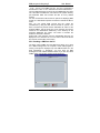
2.4.4. Routing Table
By selecting the "Routing" rectangle in the "Programming Area" the
"EDITING ROUTE LIST RECORDS" window will be displayed.
Important: For Brigate GSM application in the first line of EDITING
ROUTE LIST RECORDS table, you have to fill “X” in the
“number” field with” and “20” in the “Nr of Digits” field. These
values are mandatory.
30
OAM program for Brigate g3
User Manual
The routing table is a collection of maximum 20 records, each
records containing:
- index (colored in dark blue to indicate that is not editable)
- number (the prefix - the number for which a certain direction will
be chosen. The total length of the "Number" field is 8 digits. The
allowed characters are digits from '0' to '9'. Also the user can insert
in whatever place inside the number the characters 'x' which will be
interpreted by the ISDN-2-UMTS system as any figure (digit).
- direction - the direction (four possible values, assigned in
“Directions Timers” to which the call with the prefix specified in the
"Number" field will be routed.
- number of digits - this is the number of digits expected to be
received before forwarding the call through a resource.
- ignore – the number of digits to be ignored from the received
number.For instance, if you set it to 2, the first two digits will be
ignored. This is useful when assigning higher priority for certain
outgoing calls. The phone exchange inserts a digits at the beginning
of phone numbers dialled by the high priority extension. The two
mobile modules are assigned to the same carrier, but one of them is
reserved for the numbers dialled by the local subscribers with high
priority. But the firs digit is a „false” one, so in the Routing Table you
must specify „Ignore 1”, in order to ignore the first digit, which has
been used only internally, to assign a higher priority.
When making an outgoing call, the BRIGATE G3 will wait until the
dialing of the requested number is completely terminated. Waiting
for completion can generate a certain delay between dialing of
mobile number and actual selection. If this is annoying, you may
set the option “Number” accordingly to destinations most frequently
called.
Then, for these records, BRIGATE G3 will dial immediately (as
soon as it receives the last digit), without waiting anymore.
The resource (port) is allocated to the direction specified in the
"Direction" field (the maximum value allowed is 20).
You may user edit each field from the columns "Number",
"Direction" and "Nr.of Digits" (columns colored in light blue).
You must point with the mouse on the field that you want to modify.
That field will be highlighted with a black rectangle indicating that it
may be edited.
31
OAM program for Brigate g3
User Manual
You can delete or add characters. If you want to save the new
value, press the <ENTER> key; if you want to preserve the old
value, press the <ESC> key instead.
If the value is not correctly filled in, a message error ("Wrong
value") will be displayed
The "Save" action is used to load all the records into the BRIGATE
G3 system that is connected. Before the loading process, all 20
records are sorted in ascending order.
In case of a connection started with command "Connect To View..."
all columns will be displayed in dark blue.
This means you can only view the values, no edit action can be
performed in this case.
2.4.5. Directions and Timers
If you select the "Directions and Timers"
rectangle in the "Programming Area" the
"EDITING DIRECTIONS AND TIMERS"
window will be displayed.
Directions:
Here you can:
- define the direction names;
- complete the value for timer call, is mandatory “5”
- fill-in the overflow rules to be used in operation. The Brigate g3
unit box can handle a maximum of three directions.
32
OAM program for Brigate g3
User Manual
The direction can be assigned one to each UMTS port and the third
to PSTN (on the "TE" interface).
You may change the name for directions 0,1 and 2 from the default
names "Direction 0","Direction 1" and "Direction 2". Usually, you
should assign to them the names of the respective mobile carriers,
such as Orange and Vodafone. The "Direction 3" name can't be
change – it is shown in gray colour. This fourth direction is not a
real direction for routing the calls, it may used in the routing table to
force some prefixes to “non-existent”.
Usually, the two mobile modules are assigned each to a network
operator, in order to ensure the routing of calls for minimum costs.
But if a group of subscribers have higher priority, you may assign
both mobile modules for the same carriers, with direction names
such as Orange1 and Orange2. The direction Orange 1 is reserved
for the usage of the group of subscribers with higher priority.
Overflow
in the previous image there are three “Direction” rows with two
“Overflow” columns.
Each line is used for one direction and establishes the first and the
second overflow option.
The direction numbers can be Direction 0, 1 and 2.
If you want to specify that a direction does not have an overflow,
simply set that field to the same name as the direction name.
For example at the direction "1" - named "Vodafone" if you specify
"Overflow1" = "Vodafone" then no overflow will be set. This is the
default configuration.
If you specify "ORANGE" then when the direction "CONNEX" is
unavailable or busy, the direction "ORANGE" will be used to route
the call. You can also select a second overflow direction
(Overflow2) to be used in case the first overflow direction also
becomes unavailable or busy.
You may also use the Overflow feature to implement a higher
priority for a group of subscribers. Only these are assigned to the
direction Orange1, but if this direction is unavailable (the respective
mobile module is busy), it will overflow over the direction Orange2,
which is used by all the local subscribers.
33
OAM program for Brigate g3
User Manual
Timers:
"Timer Call" – you set the time interval while BRIGATE G3 waits
for the phone number to be dialed. For each record in the "Routing
Table" the expected number of digits must be dialed in specified
interval. Here you may specify a time interval, in seconds, during
which each digit is expected.
After the expiration of this period (12 sec in the above example) the
call will be routed out with the received digits.
"Timer Callback" - used to implement the callback service.
The incoming calls are treated according to the "Action", "Type"
and "Target / Nr. of Digits" fields.
First, the ID of the incoming calls is matched to the values stored in
the CLIP table. If the calling party whose identity is found the in
CLIP table (with the callback option) drops the call in a time period
less than "Timer Callback", then the BRIGATE G3 will callback the
calling party.
In the same conditions, if the calling part does not end the call
before the "Timer Callback" seconds expires, the call will be again
treated according to the "Action”, ”Type" and "Target / Nr. of Digits",
but callback action will not be performed.
Note: A validation check is performed upon the values that you
enter in the “Timer” fields.
If you enter some letters, the respective timer will be set to zero.
But if you enter an integer number larger than 12, you will see an
error message:
and the field that is in error will be shown with red color:
For both timers, the maximum value is 12 seconds.
34
OAM program for Brigate g3
2.4.6. CLIP-UMTS Table
User Manual
If you click the rectangle "CLIP UMTS" in the "Programming Area",
the "EDITING CLIP LIST RECORDS" window will be displayed:
For incoming calls, first the table with CLIP list is checked for the
received identity. If the identity is not found in the CLIP table then
the UMTS settings (DISA, OPERATOR and "Target" field) will be
analyzed.
The CLIP table is a collection of maximum 50 records, each
records containing:
- index (0 to 49, colored in dark blue to indicate that is not editable)
- number (the identity number for which a certain "Target" will be
selected. The total length of the "Number" field is 10 figures. The
allowed values are digits from '0' to '9'.
- list of actions to be performed; allowed values are "NT", "TE" and
"none". If you select "none" action for a line then the number
(identity) specified on that line will make no action. Values "NT" and
"TE" are used in the same manner as for the 3G modules settings.
The functionality is specified from the "Type" list and the target for
the call is filled in the "Target / Nr. of Digits" field.
35
OAM program for Brigate g3
User Manual
The last column, “Callback”, contains checkboxes. If a box is
checked, the callback feature is enabled for the respective phone
number.
If "TARGET" is selected from the "Type" list then an ISDN SETUP
message will be sent through the ISDN interface specified in the
"Action" list, having as called party number the with the number
read from the "Target" field.
If "DISA" is selected from the "Type" list, then the call will be
answered and an ISDN SETUP message will be sent through the
ISDN interface specified in the "Action" list. The setup message
may include or not the called party number.
Callback operation
When DISA is selected as “Type”, the caller party rings and hangs
up. Brigate g3 calls back and provides a DISA-like dial tone,
allowing the remote caller to dial a local extension.
When in the field “Type” you select TARGET instead of DISA, the
caller also party rings and hangs up. Brigate g3 calls the TARGET
extension. The local extension picks up the phone and gets callback tone. At the same time, a call to the UMTS/UMTS subscriber
is initiated. The remote UMTS/UMTS subscriber answers and is
connected with the TARGET local extension.
All other incoming calls with the missing Caller ID or with identity
not found in the CLIP table will be routed accordingly to the 3G/3G
module settings: for example to the Operator of your PABX.
Also, if the ring lasts longer than the “Timer Callback” value, the call
will NOT be treated as a callback one.
Note: If in the column “Type” you have “DISA” then the meaning of
the field “Target / Nr. of Digits” is different: instead of intended
target, you will have “Nr. of Digits”, the maximum number of digits
that are waited from the mobile network. You may specify at most
20 digits.
If you enter “0” for this field, it means no digits will be waited for
from the mobile network. The ISDN SETUP message will be sent
without any called party number in it.
You may edit each field from the columns: "Number" and "Target"
(colored in light blue). You must point with the mouse on the field
which you want to modify. That field will be highlighted with a black
rectangle, indicating that it can be edited.
You can delete or add characters. If you press the <ENTER> key
the new value will be saved, if you press <ESC> key the old value
will be preserved.
If the value you filled in is not correct, an error message ("Wrong
value") will be displayed.
36
OAM program for Brigate g3
User Manual
You can select values for the fields "Action" and "Type". Those
fields are displayed as combo-box fields. The "Save" action is used
to load the modified records into the Brigate system.
In case of a connection that was started with command "Connect
To View..." all columns will be displayed in dark blue. This shows
that you can only see the values; you are not allowed to perform
editing actions.
2.4.7. Password
This option is used to modify the password which is used for
protection of the Brigate unit whenever you require the option to
modify the configuration.
You must fill the password first in "New Password" then type it
again in "Confirm Password" fields.
If the two fields contain the same strings then the new password
will be sent to the program.
Note1: The maximum length for both fields is 8 characters.
Note2: The default password is "Aristel"; you should change it to a
password of your own choice.
2.4.8. Saving and loading system configurations
There are two icons (" ","
for saving and respectively loading
configurations. Those icons are valid only in the situation when the
connection is established by the tree command "Connect To
Modify...".
To save a configuration click the “Save” icon and the following
dialog window shows up:
37
OAM program for Brigate g3
User Manual
Enter the name you want. The configuration will be saved in the
"CONFIG" directory (located in the same directory as "isdncfg"
software). The "cfg" extension will be added to the name filled by
the user.
The configuration contains the categories, PIN codes, targets,
routing table, CLIP-UMTS table and the password.
Loading a configuration:
Click the “Load” icon to view the directory that contains all the
saved configurations.
You must select the desired configuration from the list, then press
the Load button. The configuration will be uploaded into the
BRIGATE G3 interface. You will see a progress indicator for each
of the configuration files transferred:
38
OAM program for Brigate g3
User Manual
Note1: when the user disconnects the connection (in case a. or b.
then automatically the configuration will be saved in the directory
"CONFIG" with the name "lastcfgx", where the last character 'x' is
indicating the system for which the configuration is used. In the
“Viewing CONFIGURATIONS directory” window shown previously
you can notice such a automatically saved configuration, named
lastcfg1.
Note2: It is strongly recommended that before loading a new image
file you save the current configuration, then load it again when
BRIGATE G3 operates with the new firmware. This way you are
sure that your settings will be kept.
2.4.9. Connection Examples
Some samples of interconnecting the BRIGATE G3 equipment:
1) ISDN3UMTS connected on its NT interface with a PABX TE
interface.
NT connector of the ISDN-2-UMTS linked to TE of the PABX, TE of
the PABX goes to the public ISND, and TE of the ISDN-2-UMTS
linked to the TE of the PABX only for synchronization.
The SYNCRO clock (dotted lines) is received from the PUBLIC
ISDN. The TE interface of the PABX is acting as a junction.
39
OAM program for Brigate g3
User Manual
Outgoing from PABX
If the call is to mobile networks, the PABX routes it to through the
ARISTEL BRIGATE G3 unit. The numbering is sent through the TE
junction of the PBX to the NT connector of the BRIGATE G3
interface. BRIGATE G3 performs further routing, it uses one or two
directions for the calls received from the PBX: DIR0 for module
UMTS0, one mobile network, DIR1 for module UMTS1, the other
mobile operator. The call will be routed according to the number
dialed to the respective mobile operator
If the number dialed is for the public ISDN network, the PABX
routes it through the TE junction connected directly to the public
network.
Incoming UMTS to PABX
From the 3G/3G network an incoming call will be forwarded to the
NT interface. The decision is taken depending upon the CLIP
UMTS table. If the incoming phone no. is not found in the table,
decision is taken depending on routes from the UMTS module. The
options involved are DISA, OPERATOR and the Target settings
(from the CLIP table or from the UMTS settings).
The destination of the call will be a specific local extension of the
PABX or the PABX operator.
2) ISDN3UMTS connected on its TE interface to a PABX NT
local.
The TE connector of the ARISTEL BRIGATE G3 is connected to
the NT of a local board of the PABX. Calls to public network go out
of the PABX through a TE junction. Note that in this case the NT
connector of the BRIGATE G3 unit is not used.
40
OAM program for Brigate g3
User Manual
Outgoing from PABX
The local subscriber dials the number of the local extension (NT
local) position where the BRIGATE G3 is connected. BRIGATE G3
answers with dial tone. The DISA option must be established in the
settings for TE interface. The subscriber will dial the outgoing
mobile number. The call will be routed on a 3G/3G module by
applying the routing table policy (the call is sent out into the
adequate 3G/3G network for least costs).
Note that the number of the UMTS subscriber must be dialed in
DTMF mode!
If the dialed number is for the public ISDN network, the PABX will
route the call through its TE junction which is connected directly to
the public network.
Incoming to PABX
The calls coming from the mobile networks can be routed to their
destination either through DISA or with help of an operator.
An incoming call from the 3G/3G networks will be forwarded to the
TE interface by checking the identity in the CLIP-UMTS table. In
case of missing Caller ID or the number is not found in the records,
the routing is performed by checking the UMTS settings.
The involved options are DISA, OPERATOR and the Target
settings (from the CLIP table or from the UMTS settings). The
destination of the call will be an extension of the PABX or the
operator.
3) ISDN3UMTS connected on its NT interface with PABX and
with the TE interface with the public ISDN.
Only one TE junction of the PABX is used. BRIGATE G3 is
connected through its TE interface directly to the public telephony
network. BRIGATE G3 unit is inserted transparently between the
public telephony network and the ISDN PBX.
41
OAM program for Brigate g3
User Manual
Outgoing from PABX
The PABX exchange will forward the calls to the ARISTEL
ISDN3UMTS system. The numbering is sent directly from the TE
junction into the NT connector of Brigate g3. In this case calls
coming in through NT connector can be routed through one of three
directions: UMTS0, UMTS1 and TE (to public network).
The routing is performed by the BRIGATE G3 unit, not by the PBX.
The call will be routed according to the number dialed either
through UMTS0, UMTS1 or the TE interface. The user can place
the module UMTS 0 on direction 0 and the UMTS1 on direction 1.
The TE interface will be placed on the direction 2, mandatory.
Incoming to PABX
The calls from the public ISDN are transferred transparently
towards the PABX. For this, in the configuration window of TE
interface you must select the “PassThrough” option.
The "TE" from the PABX will act as a junction.
The calls coming in from the 3G/3G networks are analyzed by
checking the identity in the CLIP-UMTS table.
If the ID is missing or the caller is not found in the CLIP-UMTS
records, routing will be performed by BRIGATE G3 according to the
settings of the UMTS module.
The incoming calls from the mobile network can be routed either
through DISA or with help of human operator.
4) ISDN3UMTS connected on its NT interface with TE interface
of PABX and with its TE interface with NT interface of the same
PABX.
The NT connector of the BRIGATE G3 linked to TE of the PABX
(one junction board). Another TE junction of the PABX goes to the
public ISDN network. The TE connector of the ISDN3UMTS goes
to the NT of a local board of the PABX.
42
OAM program for Brigate g3
User Manual
Outgoing from PABX
The outgoing calls exit through the TE connector of the PABX
junction. The PABX directs the calls to mobile networks through the
BRIGATE G3 unit. The calls will be routed according to the number
dialed through UMTS0 or UMTS1 placed on one of two directions
(for example 0 and 1). If the number dialed is for the public ISDN
network, the PABX will route the call through another TE junction
directly to the public network.
Incoming to PABX
Calls from mobile networks get into PABX via TE connector of the
BRIGATE G3 unit. When a UMTS call comes in, if the setting in the
UMTS window is OPERATOR, the call will go to the local extension
you have specified in the field “Target”.
From the PABX acts as a local call!
If the setting is DISA, the caller gets a DISA tone and he can dial
any local subscriber he wishes. Also, he can make calls to the
public network, acting as a local subscriber of the PBX.
Incoming calls from the 3G/3G networks will be forwarded to the TE
interface by checking the identity in the CLIP-UMTS table and in case
of missing ID or number not found in the records, by checking the
UMTS port settings. The UMTS options are DISA, OPERATOR and
the Target.
5) Using several BRIGATE G3 units
It is possible that you need to connect more than one BRIGATE G3
to the same PABX. For example, you want to use more than two
mobile operators for optimal routing. Alternately, you want to have
several 3G/3G modules for the same operator, if there is an intense
UMTS traffic or if one 3G/3G module is busy, the call to be routed
through another module. In this case several one BRIGATE G3
units (2, 3 or more) will be used with the same PABX. You must
ensure synchronization of all the BRIGATE G3 units.
43
OAM program for Brigate g3
User Manual
For this, clock synchronization is taken from the Public ISDN and
goes to the TE connector of the first Brigate.
Then the clock signal goes out through the SY connector of that
BRIGATE G3 to the TE connector of the second device, and so on.
You can have as many BRIGATE G3 units as you need.
Remember, the last BRIGATE G3 unit in the chain must have the
termination resistors for the TE interface activated.
2.5. "UMTS & SMS Analysis..."
With this option the user can see online the status of the 3G
modules and you may send or receive SMS.
The status of those modules is automatically read at time interval of
five seconds.
The possible states of each 3G module are:
- "OFF" - the module is not activated (on screen the module is
drawn in dark blue and the text "OFF" will be displayed)
- "Initialization" - the module is initiated by the application running
on BRIGATE G3 (on screen the module is drawn in red and the text
"INIT" will be displayed)
- "Search" - the module is searching for a 3G/3G network (on
screen the module is drawn in white and the text "SEARCH" will be
displayed)
- "Registered" - the module is registered (on screen the module is
drawn in light blue and the text "REGISTERED" will be displayed)
- "Alert" - there are two situations: when RING signal is
encountered on the input or when an outgoing call is in process
(until the called party will answer). On screen the module is drawn
in gray and the text "ALERT" will be displayed
- "Speaking" - a voice call is in progress through the respective
UMTS/UMTS module (on screen the module is drawn in dark blue
and the text "SPEAKING" will be displayed)
44
OAM program for Brigate g3
User Manual
2.5.1 SMS Activity
Under each 3G module indicator, on the OAM screen there is a box
that indicate the SMS activity for that module, SMS0 and
respectively SMS1:
You can see two numbers, first number indicates
messages which were received by the UMTS module
character "<") and the second number indicates
messages sent by the 3G module of BRIGATE G3
character ">").
the SMS
(after the
the SMS
(after the
When you select the option "UMTS Analysis..." then an
interrogation is performed on each 3G module about newly
received SMS. If new SMS are found, then the corresponding box
"SMS0" or "SMS1" will become colored in light blue as shown in the
. To the right side of
following image:
the "SMS0" respective "SMS1" character strings there is a figure
which displays the number of the new SMS that have been read.
On each SMS rectangle (both for 3G/3G
module 0 and 3G/3G module 1), if you
click the left button of the mouse then a
SMS menu will be displayed.
This menu allows you to send and
receive SMS either directly from your PC
or via e-mail:
Note: the seven menu options shown above will be displayed only
if the respective 3G module is registered to the mobile network.
In the example below, the UMTS modules are not yet registered
(they show INIT on red background, they are initializing):
Consequently, you will see only four options in the menu, because
obviously you cannot “Send a SMS” if the respective module is not
registered to the mobile network.
45
OAM program for Brigate g3
User Manual
2.5.2. SMS Parameters
This group of options regards to the facility to send the received
SMS to an email address and respective the possibility to retrieve
the emails from a mail server and to send the text content as SMS
message to the number specified in the "Subject" field of the email.
The number extracted from the subject is sent through one of the
two possible SIMs by analyzing the routing table. If the SIM which
is supposed to be used is not available (no SIM installed, initializing
phase, searching for network, or in alert phase) then the application
will use the other SIM. If the subject of a retrieved e-mail is not a
number, or if the mail includes attachments, then the email is
deleted from the mail server. Thus, it is better to use an email
account specially dedicated for this application (email to SMS via
Brigate).
The options for sending a SMS message as MAIL are:
- "Enabled" - If the checkbox is selected then the facility to send all
received SMS to an email address is validated;
- "Server" - this field contains the IP address of the mail server.
- "Source Address" - the source email address
- "Destination Address" - the destination email address. This
address is the default destination address; the OAM software can
also check for an email address in the beginning of a SMS
message. If "Mail Character" (in the example the used character is
'#') or '@' is found before the first space character, then the SMS
content will be sent to the e-mail address found there. If no mail
character is found, the SMS message will be sent to the default email address.
- "Subject" - this field followed by the number from where the SMS
was received will be displayed in the "Subject" column of the mail
client.
46
OAM program for Brigate g3
User Manual
- "From Name" - this field will be displayed in the mail client in the
"From" column;
- "Destination Name" - this field will be displayed in the mail client
in the "To" column;
The options for receiving MAIL messages in order to be sent as
SMS messages are:
- "Enabled" - If the checkbox is selected then the facility to connect
and retrieve mail messages is validated;
- "Server" - this filed contains the IP address of the mail server.
- "Name" - the name to be used to connect to the mail server
- "Password" - the password to be used to connect to the mail
server
- "Send Confirmation" - if this option is enabled, then a
confirmation of sending the SMS message (from the email
message) will be send to the email address from which the email
was sent.
SMS Parameters:
- "Center0" - the phone number of the center for SMS of the
respective UMTS operator - for UMTS0;
- "Memory0"- SMS memory location for UMTS0: "MT" (module) or
"SM" (SIM);
- "Center1" - the phone number of the center for SMS of the
respective UMTS operator - for UMTS1;
- "Memory1"- SMS memory location for UMTS1: "MT" (module) or
"SM" (SIM);
2.5.3 Billing
Performs billing (taxation) over the routed calls.
Once the OAM application is connected to a Brigate g3 system, the
OAM program will query at predefined time intervals, the equipment
on billing records.
The ISDN billing information contains the following fields:
- time of the call - is filled when the ISDN system is equipped with
a RTC chip.
- source of the call (UMTS0, UMTS1, NT or TE). In case of callback calls the indication will be for UMTS - "cbt" for callback with
target or "cbd" for call-back on DISA.
- identity of the call
- destination (UMTS0, UMTS1, NT or TE, none)
- number dialled
- selection time (call connecting time in seconds)
- speaking time (call time in seconds)
47
OAM program for Brigate g3
User Manual
Using the fields at the bottom, you can filter records by filling the
time periods and selecting the "Filter" button, or extract records
through "Extract" button and extract periods. Records are extracted
into the archive defined in "To" field. Archives content can be
viewed through the "View" button.
48
OAM program for Brigate g3
User Manual
2.5.4. Viewing Received SMS
To view all SMS messages received on both 3G/3G modules you
must select the option "SMS Received" from the menu shown
above. A new window (called "VIEWING RECEIVED SMS") will be
displayed; the window contains all the SMS received by the
BRIGATE G3 unit.
The window contains several columns:
- "SIM" - number of the sim card, 0 or 1. Indicates the 3G/3G
module from which the SMS is received (SIM0 or SIM1);
- "Number" - the phone number from which the SMS was send;
- "Time" - the time and date when the SMS was received;
- "Text" - the received text from the SMS. The text is separated on
several lines if inside the text there are found characters <CR> or
<LF>;
The incoming SMS, for each BRIGATE G3 system, are stored into
a file called "readsms.bin", file located in the system directory.
You may use the filter "Filter records on period" for displaying
records on a selected period of time. To activate the filter click the
button "Filter".
You can also extract records from the current SMS file
("readsms.bin") by means of the filter "Extract records on period".
You must fill the time periods and the destination file (this file must
have "rcv" extension and will be located in the "ARCHIVES"
subdirectory of the system directory). The button to activate the
command is "Extract".
49
OAM program for Brigate g3
User Manual
Received messages are stored in “rcv” binary files. All files with
"rcv" extension from the "ARCHIVES" directory are displayed in the
"Archives" list. Then you can select a file from this list and view the
content with "View" button.
2.5.5. Viewing Sent SMS
To view all SMS that were sent on both UMTS modules you must
select the option "SMS Sent". A new window (called "VIEWING
SENT SMS") will be displayed, the window contains all the SMS
messages sent through modules UMTS 0 or UMTS 1.
This window also contains several columns, like the one for
received messages:
- "From" - the source of the SMS message; the SMS can be sent
from "MAIL" (e-mail) or "PC" (the computer where OAM program is
running).
- "SIM" - number of the SIM card, 0 or 1. Indicates the 3G/3G
module through which the SMS was sent (SIM0 or SIM1);
- "Number" - the phone number where the SMS was sent;
- "Time" - the time when the SMS was sent. If the time is displayed
together with the “ER” letters it means an error occurred when
sending the SMS. In case of successful transmission, it receives an
OK from the 3G/3G module. BRIGATE G3 tries to transmit the text
messages up to three times, then gives up. The unsuccessful
message is deleted from the queue and the “ER” letters are shown
to indicate the error;
50
OAM program for Brigate g3
User Manual
- "Text" - the text of the SMS was sent. The text is separated on
several lines if <CR> or <LF> characters are found inside the text;
The sent SMS messages are stored for each BRIGATE G3 system
into a file called "sendsms.bin", file located in the system directory
(the dedicated folder that contains the files for every defined
system).
You can use the filter "Filter records on period" for displaying SMS
records on a selected time period. The button to activate the filter is
"Filter".
Also, you may extract SMS records from the current file
("sendsms.bin"), using the filter "Extract records on period". You
have to fill the time periods and the destination file name for the
extracted SMSs. This file must have "snd" extension and will be
located in the "ARCHIVES" subdirectory of the directory for the
respective BRIGATE G3 system. The button to activate the
extraction command is "Extract".
All files with "snd" extension from the "ARCHIVES" directory are
displayed in the "Archives" list. You can select a file from this list
and view the content with "View" button.
2.5.6. Sending a SMS from the PC
The option "Send a SMS" from the SMS menu allows you to send
out a SMS message from the computer, where OAM program is
running. This option is displayed only if the UMTS module is in the
state "Registered" or "Speaking". You may send out SMS
messages on both modules 3G/3G modules. If you click the "Send
a SMS" option, the following window will be displayed:
51
OAM program for Brigate g3
User Manual
You must type the destination of the SMS in the "SMS destination
phone number" field and then enter the text to be transmitted by
SMS in the area "SMS content". You can write it directly or import it
from another application with “Copy” and “Paste” commands from
the Windows operating system.
2.5.7. SMS2MAIL and MAIL2SMS
Besides sending SMS from the computer connected to Brigate g3,
the OAM program performs for you email-to-sms and sms-to-email
conversion functions. Those two options concern the facility to send
the received SMS to an email address and respectively to retrieve
the e-mails from a mail server and to send the text content as a
SMS message. The SMS is sent to the phone to the number
specified in the "Subject" field of the email.
If the Subject of a mail message is not a number or of the mail
include attachments, then the respective e-mails will be deleted
from the server.
Thus, it is better to use an e-mail account specially dedicated for
this application (email-2-SMS via Brigate g3).
Based upon the number extracted from the “Subject” field, the SMS
is sent through one of the two possible 3G/3G modules by
analyzing the routing table. If the 3G/3G module which is supposed
to be used is not available then the application will use the other
module instead. The 3G/3G module may be unavailable because:
no SIM card installed, initializing phase, searching for network, or in
alert phase.
For using this feature, in the same directory where the "isdncfg.exe"
is located a text file must be created in order to define the
parameters for sending and receiving MAIL. The name of that file
must be "smsinfo.txt". This configuration file is automatically
created by means of the option “SMS Parameters”.
The program also features automatic selection of the destination email address (see detailed description).
The options for sending a SMS form e-mail are:
- "Allow" - options are: "yes" or "no". The facility to send all received
SMS to an email address is validated if the "yes" option is selected;
- "Server" - this field contains the IP address of the mail server.
- "Source Address" - the source email address
- "Destination Address" - the destination email address. This is the
default destination address.
52
OAM program for Brigate g3
User Manual
The OAM software can also check for an email address in the
beginning of a SMS message. If "Mail Character" (in the example
the used character is '#') or '@' is found before the first space
character, then the SMS content will be sent to the e-mail address
found there. If no mail character is found, the SMS message will be
sent to the default e-mail address.
- "Subject" - this field (followed by the number from where the SMS
was received) will be displayed in the "Subject" column of the mail
client.
- "From Name" - this field will be displayed in the mail client in the
"From" column;
- "Destination Name" - this field will be displayed in the mail client in
the "To" column;
Note: all those fields are preceded by the characters "s ", from
send. You must fill the “…” fields after the comma character (",").
The options for receiving SMS from e-mail are:
- "Allow" - options are: "yes" or "no". If the "yes" option is selected
then the facility to connect and retrieve mail messages is validated;
- "Server" - this filed contains the IP address of the mail server.
- "Name" - the user name to be used to connect to the mail server
- "Password" - the password to be used to connect to the mail
server
- “Confirmation” - if the “yes” option is selected then a confirmation
message will be send at the e-mail address from which the SMS
has been sent
Note: all those fields are preceded by the characters "r ", from
received. An example is provided below where all fields are shown.
You must fill the “…” fields after the comma character (",").
Content of the "smsinfo.txt" file:
#send MAIL parameters
s Allow, yes
s Server,...
s Source Address,...
s Destination Address,...
s Subject,...
s From Name,...
s Destination Name,...
s Mail Character, #
# receive MAIL parameters
r Allow, yes
r Server,...
r Name,...
r Password,...
r Confirmation, yes (or no)
53
OAM program for Brigate g3
User Manual
The option "SMS2MAIL" will display a list of the SMS received on
both 3G/3G modules and sent to the email address specified in the
file "smsinfo.txt". There is a waiting queue which can store (in
absence of a connection to the mail server) up to 1.000 messages
to be sent later to an email address.
The window called "VIEWING SMS2MAIL REPORT" will contain all
e-mails sent to the mail server.
The columns displayed are:
- "Subject" - the subject of the mail;
- "Time" - the time and date when the SMS was received;
- "SIM" – 0 or 1, the indication of the UMTS/UMTS module from
where the SMS was received;
- "Status" - the status of the mail: "Sent" when the mail was sent or
"Unsent" when the mail was not sent yet;
- "Send Time" - the time when the mail was sent; this field is filled
only when the "Status" field is indicating a sent mail;
- "Text" - the text of the mail. Each character <CR> or <LF> is
replaced with a space character (" ");
The user can delete records from the queue by filling the "Delete"
filter and by selecting the "Delete" button.
The option "MAIL2SMS" will display a list of the mail messages
retrieved from a mail server. There is a waiting queue which can
store up to 1.000 messages to be sent out through a 3G/3G
module.
The window called "VIEWING MAIL2SMS REPORT" will contain all
emails received from the mail server and sent out through a 3G/3G
module as SMS messages.
The displayed columns are:
- "Number" - the destination mobile phone number;
- "Address" - the e-mail address from where the mail was received;
- "Receive Time" - the time and date when the mail was received;
- "Status" - the status of the SMS: "Sent" when the SMS was sent
or "Unsent" if the SMS was not yet sent;
- "SIM" - the indication of the UMTS module through which the SMS
was sent;
- "Send Time" - the time when the SMS was sent; this field is filled
only when the "Status" field is indicating a sent SMS;
- "Text" - the text of the SMS. Each character <CR> or <LF> is
replaced with a space character (" ");
The user can delete records from the waiting queue by filling the
"Delete" filter and by clicking the "Delete" button.
Note: the application connects to the mail server and retrieves all the mails.
A SMS message will be sent only for the mails which contain as "Subject"
the destination phone number. If the "Subject" contains non-digit characters,
then the respective message will be deleted.
Also the messages are deleted if they do contain attachments.
54
OAM program for Brigate g3
User Manual
Auto select
A very useful feature of the SMS2MAIL routine is its “automatic
address selection” capability. The program searches the text of the
SMS for the Mail Character, which may be “#” or the well-known
"@" symbol. If such a symbol is found before the first blank space,
the program extracts the mail address from the text of the
message.
If the specified mail address is valid, then the e-mail message will
be sent to the respective address. If the address does not exist, the
e-mail will be sent as usual, to the address specified in the
configuration file "smsinfo.txt"
Example:
If the text of the SMS is [email protected] greetings! this
means that the text “greetings!” will be sent by e-mail to the
address [email protected], if this is a valid e-mail address.
55
OAM program for Brigate g3
User Manual
2.5.8. Analyzing a GSM /UMTS port
Click the “UMTS & SMS
Analysis” option of the tree-like
structure then go to an active
mobile module.
If you select a 3G/3G module which is in the state "Registered" or
"Speaking" then the “UMTS Analysis Port 0/1” window will be
displayed. The images will be a little different, according to the type
of the modules, which may be either UMTS module or UMTS
module.
A UMTS module will display this info:
While an UMTS module will show:
56
OAM program for Brigate g3
User Manual
As shown above, the "UMTS Analysis Port x" for one of the ports 0
or 1 will contain several zones, as follows:
• information about the 3G/3G module and the mobile network, the
fields shown below:
the manufacturer
the model
the version of the respective UMTS module
IMSI (International Mobile Subscriber Identity) code
Status of registering to the network (such as registered and
roaming above)
PIN code (if the PIN code is required) or status (ready if no
PIN code is need)
name of the operator for the respective mobile network
level of the received signal (in dBm)
identification of the respective mobile cell, if the network
and the module support this feature.
The window periodically runs monitoring over the respective UMTS
module, in order to read the reception level (shown in dBm) and the
identification of the current mobile cell (for Brigate system - which is
working with UMTS modules).
All of the previous fields are read-only (they are just displayed, they
can’t be edited). The read-only values are written with dark grey
color. But the fields to the right can be edited; their values are
shown in black. The fields that you may change are:
- Level
Depending on UMTS or UMTS modules type, the level is presented
in different format: for UMTS modules there is just one LEVEL; for
UMTS modules there is a level for input and another for output.
57
OAM program for Brigate g3
User Manual
- SMS Center. It is the phone number of the center for SMS of the
respective UMTS operator. The SMS Center is the one through
which SMS originated from mobiles are transmitted. To find out this
address for your current 3G/3G provider, use a mobile phone
where you insert the SIM card. Get into the Menu of the mobile
phone, option “Messages”. Select “messages settings” and then
“default profile”. Now the screen of the mobile telephone should
display something like “+40722004000”, that is the phone number
of the message center. If no number is shown, you should enter it
and save it with “Ok”. The maximum length of this address is 20
digits.
"Type" field refers to the type of address for the SMS Center. To
make the changes, the buttons "Set" located on the same line as
"SMS Center" and "Type" must be also be pressed.
The confirmation message is "SMS Center has been updated" as
shown below:
- SMS memory. The location of the memory, where the SMS
messages will be stored.
From the drop list you can select either "MT" for the memory of the
UMTS/UMTS module or "SM" for the memory of the SIM card.
If you choose SM, the messages are stored into the SIM, so you
may take the respective SIM card off the BRIGATE G3 unit and
read it in another mobile phone.
To make changes for memory location, you must press the button
"Set" located on the same line as "SMS Memory". The confirmation
message is "The memory location has been changed".
58
OAM program for Brigate g3
User Manual
The message above also shows a set of figures related to stored
SMS: the storage capacity of the SIM is of 40 received messages,
but currently there are none (0) stored.
The second set of figures refers to transmitted SMS, etc.
- LEVEL
You can modify the audio level both for the output (hearing). The
range of audio level is 0 to 3.
The sound levels can be decreased or increased individually with
the buttons "-" and respectively "+".
The selected level is shown as a bar-graph.
You may use the "Default" button located to the right to restore the
default level for input and/or output.
This default value is 1, in a range from 0 to 3.
Note1: Do not change these parameters unless absolutely
necessary, as this may affect the voice quality.
Note2: If you make a connection with a BRIGATE G3 unit through
one of the options: “Connect To View…”, “Connect To Modify…” or
“UMTS Analysis” and there is a supply voltage failure or the
connection cable is unplugged you will get an error message:
“Missing Equipment or Cable Unplugged”.
59
OAM program for Brigate g3
User Manual
2.6. "Loading Image File"
This facility allows you to load a new version of the firmware
application running on the BRIGATE G3 system (to perform a
firmware update).
The image files have the extension "hex" and are available form the
website of the ARISTEL company.
If you select this option, a browsing dialog box will show up:
You must select the new software image to be loaded (with "hex"
extension), then the program will ask you for the system’s access
password:
You can follow the upload process in the window called "Loading
new image".
60
OAM program for Brigate g3
User Manual
Also, you may follow the progress of the upload on the status bar,
in the columns 2 and 3 (from left to right). The new software image
is divided in packets which are sent to the Brigate g3 system. The
reception of each packet must be confirmed.
The second column will display the text ">Loading Packet xxx From
yyy", where "xxx" is the current loaded packet and 'yyy' is the total
number of packets to be received. The third column displays
"<Packet xxx received", where 'xxx' is the current confirmed packet.
When the loading
process is ended
without
errors,
you will see this
confirmation
message:
Important notices related to the loading of a new version of
application software into Brigate: Be careful when you load an
update file. If you select a wrong kind of file, or if for different
reasons firmware upgrading fails, the BRIGATE G3 equipment will
no longer operate correctly. In some cases you will need to contact
the manufacturer for repairs. To avoid this, follow carefully the rules
indicated here:
•
Always backup!
Before loading of the image file (menu "Loading Image File") it is
strongly recommended that you save the current configuration of
your Brigate g3 unit. Click the icon "Save current configuration".
Then, after you performed the loading of image file, reload the
saved configuration by clicking the icon "Load configuration".
If you don’t do this your settings may be lost upon loading a new
image file.
•
Correct version
Make sure that you get the correct version. First, you want to make
sure that the file you load is newer than your current firmware
version. Second, check that it is the variant that is right for your
equipment. The BRIGATE G3 devices may have two types of
processors: codes are _64 and respectively _128.
Make sure that the image file that you load is suited for your
processor. If you have older equipment, that doesn’t show the _64
or _128 termination, it means you must look for firmware versions
type _64.
61
OAM program for Brigate g3
User Manual
•
No interruption
Never turn off the BRIGATE G3 equipment or the computer while
the firmware is being overwritten.
Make sure that the adapter and your PC don’t turn off during
update. It is better to use an uninterruptible power supply (UPS) for
this purpose.
•
Always backup!
Remember that updating the firmware on the BRIGATE G3
equipment could cause some or all of the configuration settings to
be lost, depending on the degree of change in the firmware.
Therefore it is highly recommended that you save your current
configuration before updating, then you restore it. To backup your
settings, perform a Save, update the firmware, and then Load the
saved settings, after you have updated the firmware.
•
Resuming after an interruption:
If the loading of the image file is interrupted (the mains power fails,
the operating system on the PC stops, the cable is disconnected,
etc) before reaching its normal ending, the new software may not
be fully installed so the equipment it won’t work.
To correct this, you should first reset Brigate g3 (by taking off the
supply jack for 10 seconds) and try again to load the image file.
If this is not successful, you must change a jumper setting to
perform forced loading of the application.
JP 5 is located near the top left corner of the printed circuit board of
Brigate g3, see indication of its position in the following drawing:
62
OAM program for Brigate g3
User Manual
You must follow the procedure steps described below:
power down Brigate g3 (unplug the supply adapter)
open the plastic case of the device and look at the printed
circuit board
locate jumper JP5 (top left, near the connector for antenna,
as shown in the following drawing) and place a jumper on
these two pins
-
-
start up the OAM application with the “l” option. For this you
go to the MS-DOS command line and type: “isdncfg.exe–l”
from the OAM program select the menu “Loading Image
File”
choose the image file you want to load into the BRIGATE
G3 equipment. Note that in this forced mode of operation
the authentication by password will not be requested
anymore
after the loading of the image file is ended, power down
Brigate
remove the jumper from pins JP5
close the case of BRIGATE G3 equipment.
Now BRIGATE G3 can be used normally with the new image file.
Explication:
In normal operation, the boot loader is started first, upon power-up
of Brigate g3.
When the loading of a new image file has been interrupted before
normal termination, the program loaded in memory may be
corrupted, so it won’t work correctly.
To remediate this, you must place a jumper on pins JP5 to force
the boot loader to start.
Then it can load the application and download a new (correct)
image file for Brigate.
Remember to take the jumper off pins JP5 before resuming normal
operation of the BRIGATE G3 equipment!
63
OAM program for Brigate g3
User Manual
3. Print options
In all situations involving a print command a dialog box will appear.
It features two options:
- print to printer (a printer must be installed into the system of the
PC where you run the OAM program)
- print to file (in this case a file name is given, for saving data into
that file).
NOTE
Please note that the OAM program uses two different types of
windows.
There is a window for viewing content of the files and another
window for viewing or modifying system configuration and for
analyzing of 3G/3G modules or sending/receiving SMS.
This means that the action required to hide the current window may
differ, depending upon what kind of window you are in:
•
When you are working with files content you can operate
upon the tree commands for the selected BRIGATE G3
system and when you have finished you click the right
mouse button to hide the window.
•
If you are viewing a configuration, you can hide the
window by pressing right button of the mouse. If you are
connected to a BRIGATE G3 system and the configuration
window is above (on top), when clicking the right button
you will be asked if you want to disconnect.
Connection indication
To the right end of the status bar there is a colored connection
indication: its color is blue when you are connected to a BRIGATE
G3 system and is red when you are not connected to any
BRIGATE G3 system.
64
OAM program for Brigate g3
User Manual
4. SYSTEMS
4.1. Add
If you select "System > Add" the following window will appear,
asking you to add another Brigate g3 system to tree-like structure.
Directory - enter a name for the folder where the files downloaded
from the Brigate g3 system will be stored.
On you hard disk there will be created a directory in the following
format: "cfg_xxxxxxx" where xxxxxxx is the name typed in the
"Directory" field. The folder will be created on your HDD in the
same directory where the executable 'isdncfg.exe' is located.
Name - enter a name for the connection to the BRIGATE G3
system. This name is concatenated to "cfg_" and this will be the
text used in the tree structure for identifying the respective
BRIGATE G3 system.
Serial Port num - enter the serial port used for serial
communication with the BRIGATE G3 system. The default value is
COM1. This value must be in range COM1-COM12.
There is a text limit of 19 characters for the "Directory" and "Name"
fields and 2 digits for the "Serial Port num".
A value check is performed for the serial port value. If the value is
not in the range 1 - 12, an error message will be displayed and the
incorrect field will be colored in red.
65
OAM program for Brigate g3
User Manual
Also, value checks are performed upon the fields "Directory" and
"Name". If one of this values is not filled or is the same as an
already existing "Directory" or "Name" (which are used for another
BRIGATE G3 system), an error message will be displayed and the
incorrect field will be colored in red.
Save - saves the setting and adds in the tree structure a system
with the modified settings
Cancel - closes the window without saving the settings.
4.2. Remove
If you select "System > Remove" then you will see the next window:
To remove a Brigate g3 system from the tree-like structure, select
it, and then click on the 'Save' button: the selected system will be
deleted from the tree structure.
Remember that the folder (directory) on your hard disk drive won't
be deleted, you must erase it manually. If you select Cancel the
window will be closed.
Note: There is also a tree command for changing parameters of
BRIGATE G3 systems. The parameters you may change are Name
and number of serial port where BRIGATE G3 is connected.
66
OAM program for Brigate g3
User Manual
5. FACILITIES
This group of command allows you to change the aspect of the
graphic interface of the OAM program (fonts, colors), to view or
print configuration files, and also to execute different commands.
5.1. Font
If you select "Facilities > Font" the following window will be shown:
In this window you can select according to your preferences the
font, the style and size of characters. The changes will only affect
the windows that are displaying the system configuration.
67
OAM program for Brigate g3
User Manual
5.2. Colors signification
You may alter the allocation of colors used in several windows of
the OAM program.
The colors are valid for the windows: "Modify Configuration",
"Viewing Configuration", "Analyzing UMTS modules" and "Last
Configuration" of the OAM program. The default significance is
explained below:
- Dark blue - that position is available (free)
- Red - that position is in alarm
- White - that position is already used (busy)
- Light blue - that position is not installed (the checkbox "Installed"
from the window for configuring the settings of the port has not
been installed).
The red, white and light blue will be used in further developments.
There are also shown the colors used for "Text Color", "Back Color"
and "Tree Color".
All those colors can be modified according to your preferences, by
clicking on it.
You select the color you want, either from the predefined "Basic"
colors, or from the detailed zone of custom colors. The change of
colors is instant, there is no need for a “Save” button.
The "Default" button is used to restore to the original color set.
68
OAM program for Brigate g3
User Manual
5.3. View print files
This is a facility for viewing text files located in the "FORMAT"
folder. Those files are generated by printing data into files from
different locations of the OAM program.
To see a file, select its name from the list and click the button
'View'. A window for viewing/editing the file now appears.
You can also perform searches by using the buttons marked 'FIND'
and 'NEXT' or you can send the listing of the file to the printer.
5.4. LOG FILES
There are several types of files used for the OAM program for the
BRIGATE G3 equipment.
The log files are named <current date>.log and contain information
about the events that took place: date and time for the making and
respectively breaking of connections concerning the selected
BRIGATE G3 system, file transfer and so on.
Field
Description
Date
dd-mm-yy
Hour
xx:xx:xx
Event
Description of the event that was performed
The lch (changes) files are named <current date>.lch and include
information about the changes (modifications) performed to the
BRIGATE G3 system.
Field
Description
Date of change dd-mm-yy
Time of change xx:xx:xx
Modification
Description of the change that was performed
OK - the change was successfully
Status
ERROR - the change was not successful
69
OAM program for Brigate g3
User Manual
6. TREE COMMANDS
6.1. Modify parameters
If you select "Parameters" tree command the following window it
will be shown:
The Directory is shown in gray color because it is already defined,
you can’t change it.
You are allowed to change the name of the BRIGATE G3 system
and the number of the serial port used for connection (in range
COM1-COM12).
There is a length limit of 19 characters for the "Name" field and 2
digits for the "Serial Port num".
A value check is performed for the serial port value. If the value is
not in the range 1 - 12, an error message will be displayed and the
incorrect field will be colored in red.
Also, value check is performed upon the “Name" field. If this field is
not filled or the name you inserted is already existent, (which is
used for another system), an error message will be displayed and
the incorrect field will be colored in red.
70
OAM program for Brigate g3
User Manual
6.2 LAST CONFIGURATION
With this option we can see last downloaded and possibly modified
configuration for the selected BRIGATE G3 system.
If you select this option the "LAST configuration" window will be
displayed as shown below:
You will be able to view offline the last configuration: route table
and CLIP table, the settings for each 3G/3G module.
In the next example you can see the last settings for the UMTS 0
module of the BRIGATE G3 equipment that was connected to the
OAM program:
71
OAM program for Brigate g3
User Manual
Please note that "Save" button in all windows is hidden, there are
visible only the buttons “Help” and “Cancel”.
This means you cannot perform changes of the parameters, you
are allowed only to look at the already existing settings.
This is applicable for all windows in the “Last Configuration” mode.
6.3 HELP
This is the command for showing the User Manual in electronic
format.
The left pane of the help window shows an index of pre-defined
keywords where you can search for the item (Icon command, menu
command, Tree command, general considerations) you want to
learn about.
The right pane offers detailed pages structured as "Menu
description" (Systems, Facilities and so on) and respectively the
"Tree Commands".
The left pane of the help screen also includes the search facilities.
You click on the "Search" tab and enter the word or the expression
you want to look for, for example <tree structure>, then click "List
Topics" to start the search.
The help program will display all the occurrences it has found,
together with the name of the help page where they are located
and their rank (1, 2, 3 etc).
72
OAM program for Brigate g3
User Manual
Please note that, according to the general rules for text search, if
you enter several words in the "Search field", the help program will
look for occurrences of EITHER word. This is like telling the help
program <<search for “tree" OR for “structure">>.
If you want to be more specific, you should select the Boolean
operator AND instead of OR. For instance, if you want to know
about the tree structure, you must search for "tree structure", using
quotes. In this case, the help program will display only the
occurrences where ALL of the words inside the quotes are found
together.
You select one of the occurrences and click "Display" to show the
respective help page in the right pane. The words or expressions
you look for will be highlighted (marked with reverse video). If you
want to search further inside the help page, press Ctrl F and a
"Find" window will show up. You type the expression to search in
the field "Find what". You may select additional options: "Match
whole words only" and "Match case" if you want to narrow the
search. You must specify the direction of the search inside the
page, Up or Down. "Find Next" shows the following occurrence of
the word you want to search.
The Search function of the help program remembers the words you
entered, even if you close down the help screen.
73
OAM program for Brigate g3
User Manual
When you run "Help" next time the same word or expression will be
displayed.
The window of each command now has a "Help" button of its own.
This means that you no longer need to issue the "Help" command
and then search or the item of interest.
When you run a command, for instance "Parameters", you just click
its "Help" button and the respective help window will be displayed,
showing you information about that particular command.
74
OAM program for Brigate g3
User Manual
7. GLOSSARY
Here you have the explanation of some terms and acronyms used in
the user manual for the BRIGATE G3 system.
ANI - Acronym for Automated Number Identification; A number
(typically telephone number) that is sent along the phone line at the
beginning of a call. It identifies the calling party to the receiving
party. Named also Caller ID. This is used by the OAM program for
automated routing of incoming calls according to their ID.
AOC – Acronym for “Advice of Charge”, signaling protocol used to
send charging (billing) information to the phone exchange where
BRIGATE G3 is connected. Performed by means of billing pulses.
AOC is the charge for the call, computed by the mobile phone and
expressed in terms of Home Units. The charge pulses are sent at
the beginning of the call and during the call, according to two
adjustable settings: the number of initial pulses and the time delay
between two billing pulses.
Boot loader – bootstrap loader, small program that launches first
upon power up and helps loading the operating system. Any
computer system can execute only code that is stored in DRAM
memory, but the operating system is stored on hard disk drives or
Flash memory. In the case of Brigate g3, the boot loader starts first
when you power up the equipment and allows loading of the main
application that controls the ISDN to UMTS interface.
CAS - Acronym for Channel-Associated Signaling. A type of
signaling in which the signals needed to switch a given telephone
circuit are transmitted via the voice circuit itself (the same channel that
will afterwards be used for the call). Also, the signaling information can
be sent through a signaling channel permanently associated with the
voice channel.
CLIP - Acronym for Calling Line Identity Presentation. For endusers, this service is handy in order to screen incoming calls, prepare
the specific response, greeting the caller by name or looking up for
missed or unanswered phone calls. The BRIGATE G3 unit makes use
of the CLIP facility to identify the subscribers who called and route the
calls according to their Caller ID.
DID - Acronym for Direct Inward Dialing. Allows a party calling
from outside into a PABX to be connected directly to a local
extension, without need for assistance from the operator.
DISA – Acronym for Direct Inward System Access. This function
allows an outside caller to directly access a local subscriber of the
phone exchange by using DTMF codes.
DTMF - Acronym for Dual Tone Multi Frequency, also known as
"touch tone". Advanced method for dialing a number, instead of the
older Pulse mode. When you press a key on the keypad a
combination of two audio frequencies is sent on the line.
75
OAM program for Brigate g3
User Manual
IMEI - Acronym for International Mobile Equipment Identifier. 15-digit
number that uniquely identifies an individual mobile terminal wireless
device. While IMSI is subscriber-related, the IMEI is equipmentrelated. Specific for a certain mobile terminal (phone or modem).
IMSI – Acronym for International Mobile Subscriber Identity.
Unique code number (for all the world) that identifies a UMTS
subscriber to the network. Linked to the user account information
at the network operator. IMSI resides in the SIM card.
ISDN - Acronym for Integrated Services Digital Network.
Worldwide digital network providing high-speed connection
between the terminal devices, (telephone, fax machines,
computers) for a wide range of telecommunication services, using
the existing telephony infrastructure. BRIGATE G3 interfaces with
an ISND-BRI connection to one or two mobile networks.
ISND Connection Type – The interfaces of Brigate g3 may work
either in Point-to-point” mode or in and “Point-to-Multipoint” mode.
You should select this according to the type of the equipment
(digital PBX or telephone) that Brigate g3 is connected to. The
Point-to-Point is used to connect only two devices, and it uses the
DDI service (Direct Dialing In). You should use this in the most
usual case, when Brigate g3 is connected to an ISDN phone
exchange.
But when you have the Brigate g3 unit connected to one or several
ISDN phones or modem, you can no longer use the Point-to-Point.
Instead, you must use the option “Point-to-Multipoint”, which allows
you to connect several ISDN equipments (form two up to eight).
Instead of DDI, it uses the MSN service (Multiple Subscriber
Number). The “Point-to-Multipoint” connection should be used for
ISDN phones or other ISDN terminals.
PBX - Acronym for Private Branch eXchange. The PBX is a small,
private version of the larger central switching office of the phone
company. A PBX is a private telephone switch. It is connected to
groups of lines (junctions) from one or more central offices and to
all of the telephones at the location (subscribers, extensions)
served by the PBX. Current exchanges are in fact PABX,
automated PBX, which don’t require a human operator to route the
calls. BRIGATE G3 was designed to work together with an ISDN
(digital) PABX to route the calls.
Physical layer: Layer 1 in the Open Systems Interconnection
model. OSI is a standard description or "reference model" for how
messages are be transmitted in a telecommunication network.
Layer 1is the physical level, which conveys the bit stream through
the network at the electrical and mechanical level. BRIGATE G3
allows you to de-activate (disable) the physical Layer of the ISDN
connection when there are no calls.
76
OAM program for Brigate g3
User Manual
PSTN - Acronym for Public Switched Telephone Network (s).
It is the classic international fixed telephony system based on
copper wires that carry voice and data. Analog (mostly) or digital
technology is used to provide voice grade services for the users
that access that network via an analog interface.
Signaling – the totality of information exchanged between the phone
central office and the terminal device or between two phone
exchanges. These information are required in order to establish,
maintain, and clear switched telephony connections. The signaling
can be type CAS or CCS.
SMS - Acronym for Short Message Service; means the transmission
of short text messages to and from cellular phones. The messages
must be text only (no images or graphics) and not longer than 160
alpha-numeric characters. Operators of Mobile Phone Networks use a
spare data channel to send SMS messages. You may send SMS to
another mobile subscriber, the mobile operator can send you phone
settings over-the-air or commercial companies may send dedicated
content to your mobile terminal. Also, the SMS2MAIL and MAIL2SMS
functions of the OAM program perform automatic conversion between
e-mail and SMS messages.
TA - Terminal Adapter. The terminal adapters operate adaptation
between ISDN interfaces and standard terminals. When you
connect a Terminating Equipment (phone, digital fax machine) to
ISDN, it must be an ISDN-compatible device (TE-1). Other devices,
for example a computer, are called TE-2 and must be connected to
ISDN via a Terminal Adapter. If you want to connect analog phones
to BRIGATE G3, you must use such a terminal adapter.
TEI Management – Acronym for “Terminal Equipment
Identification”. This is an internal ISDN identification of connected
phones. Brigate g3 lets you set the TEI management either on “0”
or on “auto”, depending upon the type of ISDN connection used.
For the Point-to-point connection (default), a value of “zero” must
be used for TEI.
If you change the connection type “Point-to-multipoint”, TEI
Management field switches to “Auto”, which is the value that must
be used in case of point-to-multipoint connection (up to eight ISDN
devices connected to the same interface).
Timer Call – timer for the interval, while BRIGATE G3 waits for the
digits of the phone number to be dialed.
Timer Callback – timer used to implement the callback service.
Establishes the time threshold, to discriminate between callback
and ordinary calls. If the calling party whose identity is found the
CLIP table (with the callback option) drops the call in a time interval
less than "Timer Callback", then BRIGATE G3 will call back the
calling party. However, if the calling party does not end the call
before the "Timer Callback" seconds expires, no callback action will
be performed.
77
OAM program for Brigate g3
User Manual
www.aristel.com.au
78