1
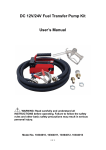
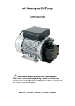
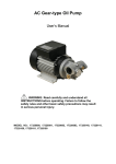
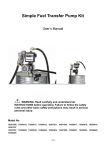
DC Oil Transfer Pump
User’s Manual
WARNING
Read carefully and understand all INSTRUCTIONS before operating.
Failure to follow the safety rules and other basic safety precautions may result in
serious personal injury. Save these instructions in a safe place and on hand so
that they can be read when required.
Model No.: 17520100, 17520101, 17520102, 17520103
A. DECLARATION OF CONFORMITY
DECLARATION OF CONFORMITY
IN CONFORMANCE WITH THE DIRECTIVES
98/37/EEC (MACHINERY)
73/23/EEC (PRESSURE VESSELS)
89/336/EEC (ELECTOR-MAGNETIC COMPATIBILITY)
THE MANUFACTURER
INTRADIN (SHANGHAI) MACHINERY
118 DUHUI ROAD, MINHANG DISTRICT, SHANGHAI, 201109 CHINA
DECLARES THAT THE FOLLOWING PUMP MODELS: 17520100, 17520101, 17520102, 17520103
CONFORMS TO THE FOLLOWING EUROPEAN REGULATIONS:
EN292-1-92 – Safety of Machinery – General Concepts, basic principles for design – terminology, basic
methodology
EN292-2-92 – Safety of Machinery – General Concepts, basic principles for design – specifications and
technical principles
EN294-93 – Safety of Machinery – safe distances to prevent the operator’s upper limbs from reaching
dangerous areas
EN60034-1-2000 – Rotating electrical Machinery – nominal and functional specifications
EN60034-5-2001 – Classification of grades of protection for the housings of rotating electrical machinery
EN61000-6-3 – Electro – magnetic compatibility – generic emission standards
EN61000-6-1 – Electro – magnetic compatibility – generic immunity standards
EN55014-1-00(A1/99-A2/99) –Limits and methods for measuring radio disturbance characteristics
EN55014-2-97 – Electrical motor – operated and thermal appliances for household and similar purposes,
electric tools and similar electrical apparatus
EN60204-1-98 –Safety of machinery – electrical equipment of machines
B. MACHINE DESCRIPTION
Pump: Electric self-priming rotary external gear pump, equipped with a by pass valve
MOTOR: Brush motor powered by continuous current, low voltage, with intermittent cycle, closed type, IP55
protection class according to CEI EN 60034-5.
C. TECHNICAL INFORMATION
Description
Europe
America
17520100
17520101
17520102
17520103
Voltage
12V
24V
12V
24V
Power
150W
150W
150W
150W
Current
40A
30A
40A
30A
Flow Rate
10LPM
10LPM
10Quarts/min.
10Quarts/min.
Pressure
4 bar
4 bar
60 PSI
60 PSI
Inlet/Outlet
3/4” BSP
3/4” BSP
3/4” NPT
3/4” NPT
Rated Speed
2900 RPM
2900 RPM
2900 RPM
2900 RPM
D. OPERATING CONDITIONS
D.1 ENVIRONMENTAL CONDITIONS
Temperature: min-10°C/max+60°C
Relative humidity: max. 90%
ATTENTION!
The temperature limits indicated are applied to the pump components and must be respected to avoid
possible damage or malfunction.
It is understood, nevertheless, that for a given oil, the real functioning temperature range also depends on
the variability of the viscosity of the oil itself with the temperature. Specifically:
z The minimum temperature allowed -10℃) could cause the viscosity of some oils to greatly exceed the
maximum allowed, with the consequence that the static torque required during the starting of the pump
would be excessive, risking overload and damage to the pump.
z The maximum temperature allowed (+60℃) could, on the other hand, cause the viscosity of some oils
to drop well below the minimum allowed, causing a degradation in performance with obvious reductions
in flow rate as the back pressure increases.
D.2 ELECTRICAL POWER SUPPLY
Depending on the model, the pump must be supplied by a continuous current line whose nominal values are
shown in the table in Paragraph C-TECHNICAL INFORMATION.
The maximum acceptable variations from the electrical parameters are:
Voltage: +/-5%of the nominal value
ATTENTION!
Power from lines with values outside of the indicated limits can damage the electrical components.
D.3 WORKING CYCLE
The pumps are designed for INTERMITTENT use with a 30-minute work cycle under conditions of maximum
back pressure
ATTENTION!
Functioning under by-pass conditions I only allowed for brief periods of time(2-3minutes maximum).after a
work cycle of 30 minutes, wait for the motor to cool.
D.4 FLUID ALLOWED/FLUID NOT ALLOWED
ALLOWED: Oil with a Viscosity from 50 to 600cst (at working temperature)
NOT ALLOWED
RELATED DANGER
Gasoline (Petrol)
Fire - explosion
Inflammable liquids with PM < 55℃
Fire - explosion
Water
Oxidation of the pump
Liquid food products
Contamination of same
Corrosive Chemicals
Corrosion of the pump
Injury to people
Solvents
Fire – explosion
Damage to gasket seals
E. MOVING AND TRANSPORTING
Given the limited weight and size of the pumps (See dimensions and weights), moving the pumps does not
require the use of lifting equipment.
The pumps are carefully packed before shipment. On receipt, check the packing materials and store in a
dry place.
F. INSTALLATION
F.1 Preliminary Inspection
z Check that the machine has not suffered any damage during its transport or warehousing.
z Clean the inlet and outlet openings with care, removing any dust or packing residue.
z Make sure that the motor shaft turns freely.
z Check that the electrical information corresponds with what is shown on the label.
F.2 MECHANICAL INSTALLATION
The pumps can be installed as follows:
a) Horizontally
b)To the wall
With pump body up wards
c) To the wall.
With pump body aside
only with check valve installed
d) To the wall
With check valve installed
It is recommended to install a check valve in order to resume the system operation quickly and easily even
after the first priming
ATTENTION!
Under conditions C and D, a check valve is to be installed. Moreover, during the initial start-up phase, the
suction tube is to be filled with oil.
Fix the pump using screws of a diameter suitable for the provided fixing holes as indicated in the drawing
“Dimensions and weights”.
ATTENTION!
THE MOTORS ARE NOT OF AN ANTI-EXPLOSIVE TYPE
Do not install them where inflammable vapours could be present.
ATTENTION!
It is the installer’s responsibility to provide the line accessories necessary for the safe and proper functioning
of the pump.
The use of accessories that are inappropriate for use with oil can cause damage to the pump or people as
well as pollution
G. INITIAL START-UP
The pumps are self-priming and, therefore, able to draw oil from the tank even when the suction hose is
empty on start-up.
The priming height (distance between the surface of the oil and the inlet opening) must not exceed 2.5
meters
ATTENTION!
Wetting the pump. Before starting the pump, wet the inside of the pump body with oil through the inlet and
outlet openings.
If the pump is already installed, the operation can be performed by removing the cover of the chamber filling
the internal chamber with oil and placing the cover again, paying attention to the O-ring seal.
In the priming phase the pump must blow the air that was initially present in the tubing into the line, therefore,
it is necessary to keep the delivery open.
When the tube is filled with oil, the purging phase is concluded.
ATTENTION!
If a foot valve was not installed, install the pump in a position so that oil is always present in the gear
chamber.
If the foot-valve seal is not perfectly tight, the suction tube may be emptied and the operation of initial
start-up described above must be repeated.
The priming phase may last from several seconds to a few minutes, depending on the characteristics of the
system.
If this phase is excessively prolonged, stop the pump and verify:
z That the pump is not running completely ”dry”
z That the suction hose guarantees against air infiltration and is correctly immersed in the fluid to be
drawn
z That the filter in the suction circuit, if any, is nit blocked
z That the delivery hose allows for the easy evacuation of the air
z That the priming height is not greater than 2.5 meters
z The exact rotation direction of the motor: it must be in a counter-clockwise considering the motor from
pos. 1 of the exploded diagram.
When priming has occurred, after reattaching the delivery nozzle, verify that the pump is functioning within
the expected ranges, possibly checking:
that under conditions of maximum flow the energy drawn by the motor falls within the values indicated on the
label
H. DAILY USE
NO particular preliminary operation is required for every day use of these pumps.
z Before starting the pump, make sure that the ultimate shut-off device (delivery nozzle or line valve) is
closed. If the delivery has no shut-off device (free delivery), make sure that it is correctly positioned and
appropriately attached to the delivery tank.
z Make sure that the tank is filled with a quantity of oil greater than the quantity to be supplied (running
dry could damage the pump)
z Turn the on-switch present on some pump models or the start/stop switch installed on the electrical
power line
z
Open the delivery valve or activate the delivery nozzle, gripping it securely
ATTENTION!
Fluid exits at high pressure from a delivery nozzle fed by the pump.
Never point the outlet of the nozzle towards any part of the body.
Close the delivery nozzle or the line valve to stop delivery .the pump will automatically enter by-pass mode.
ATTENTION!
Functioning with the delivery closed is only allowed for brief periods (2 to 3minutes maximum). functioning
under nominal conditions in limited to a work cycle of 30 minutes. If this time is exceeded, you have to run
off the pump and wait for it to cool after use, make sure the pump us turned off.
Stop the pump.
I. PROBLEMS AND SOLUTIONS
PROBLEM
POSSIBLE CAUSE
CORRECTIVE ACTION
Motor does not turn
Lack of electric power
Check electrical connections
and the safety systems
Rotor jammed
Check for possible damage or
obstruction of the rotating
components
Motor problems
Contact the service department
Fuse burnt out
Replace the fuse
Low voltage from the electrical
power supply
Adjust the voltage within
anticipated limits
Excessive oil viscosity
Verify oil temperature and
warm it to reduce excessive
viscosity
Low level in the suction tank
Fill in the tank
Foot valve blocked
Clean and/or replace valve
Filter blocked
Clean the filter
Excessive suction pressure
Lower the pump with respect to
the level of the tank or increase
the cross-section of the hose
High load loss in the delivery circuit
(running with by-pass open)
Use shorter hose or of wider
diameter
By-pass valve blocked
Detach the valve, clean or
replace it
Air in the pump or suction hose
Check the seal of the
connection
Narrowing of the suction hose
Use a hose appropriate for
working under suction pressure
Low rotation speed
Check the voltage at the pump.
Adjust the voltage or use
cables of greater cross-section
Excessive oil viscosity
Verify the oil temperature and
warm it to reduce the
excessive viscosity
Motor turns slowly
when starting
LITTLE OR NO
FLOW
HIGHER PUMP
NOISE
LEAKAGE FROM
THE PUMP BODY
HIGH
ABSORPTION
Cavitations
Reduce the suction pressure
Irregular by-pass functioning
Deliver until the air in the
by-pass system is purged
Presence of the air in the oil
Wait for the oil in the tank to
settle
Damage to the mechanical seal
Check and replace the
mechanical seal
The cover is screwed too tightly
Loosen the screws of the
cover
Excessive oil viscosity
Verify the oil temperature and
warm it to reduce the
excessive viscosity
J. MAINTENANCE
z
z
z
z
On a weekly basis check that the hose joints have not loosened, to avoid any leakage
On a monthly basis check the pump body and clean it removing any impurities.
On a monthly basis check and clean the filters placed at the pump inlet.
On a monthly basis check that the electric power cables are in good condition.
K. NOISE LEVEL
Under Normal operating conditions noise emission for all models does not exceed the value of 70 db “A” at a
distance of 1 Meter from the electric pump.
L. EXPLODED DIAGRAMS AND SPARE PARTS
o.
Description
Qty
1
SCREW M6x10
4
2
Gear coverplate
1
3
O-RING 58.42x2.62
1
4
Driver key
1
5
Gear
2
6
Axile bush
2
7
Pump body
1
8
Oil seal
1
9
elastic collar
1
10
ball bearing
1
11
Motor
1
12
SCREW M5X10
2
13
bracket
1
14
Valve plug
2
15
O-RING 11.1*1.78
2
16
compression helical spring
1
17
by-pass valve
1