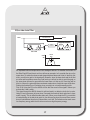
1
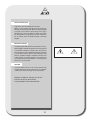
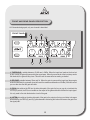
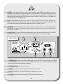
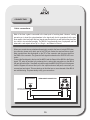
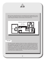
APEX NV
Schoebroekstraat 62
3583 Beringen (Paal)
BELGIUM
Tel: + 32 (0)11 28 61 91
Fax: + 32 (0)11 25 56 38
email: [email protected]
website: www.apex-audio.be
Environmental precaution
EU Directive 2002/96/EC
Remark: This notice applies only to countries within the European Union
(EU) and Norway
Electrical and electronic equipment may contain hazardous substances for
humans and their environment.
The “crossed out wheelie bin” symbol present on the device and represented above is there to remind one of the obligation of selective collection of
waste. This label is applied to various products to indicate that the product
is not to be thrown away as unsorted municipal waste. At the end of life,
dispose of this product by returning it to the point of sale or to your local
municipal collection point for recycling of electric and electronic devices.
Customer participation is important to minimize the potential affects on the
environment and human health that can result from hazardous substances
that may be contained in this product.
Please, dispose of this product and its packaging in accordance with local
and national disposal regulations including those governing the recovery
and recycling of waste electrical and electronic equipment. Contact your
local waste administration, waste collection company or dealer.
INTRODUCTION
Thank you for buying the Apex dBG-8. The Apex dBG-8 is part of the Apex dB-series of professional
audio equipment offering unprecedented quality for money. The dBG-8 offers 8 channels of gating
in an ultra compact package but without compromising quality. If you are used to working with noisegates you will immediately find your way about the dBG-8. However if you would like to make the best
use of the dBG-8 or would like to know more about nois-gates in general, we invite you to read this
manual.
UNPACKING AND SAFETY
Follow all warnings and instructions.
Install in accordance with the manufacturer’s instructions.
Proper power cord
This product is intended to operate from a regular 220V
AC outlet
Use only the power cord and connector specified for the
product and your operating locale. Use only a cord that
is in good condition. Protect the power cord from being
walked on or pinched, particularly at the plug, convenience receptacle, and the point where the cord exits from
the apparatus.
Grounding
Operating location
The chassis of this product is grounded through the
power cord. To avoid electric shock, plug the power cord
into a properly wired receptacle before making any connections to the product.
A protective ground connection, by way of the grounding
conductor in the power cord, is essential for safe operation. Do not defeat the safety purpose of the
grounding plug. The grounding plug has two blades and a
third grounding prong. The third prong is provided for your
safety. When the provided plug does not fit your outlet,
consult an electrician for replacement of the obsolete
outlet.
Do not operate this equipment under any of the following
conditions: explosive atmospheres, in wet locations, in
inclement weather, improper or unknown AC mains voltage, or if improperly fused. Do not install near any heat
source such as radiators, heat registers, stoves, or other
apparatus (including amplifiers) that produce heat. Unplug
this apparatus during lightning storms or when unused for
long periods of time.
Power Source
Stay out of the box
To avoid personal injury (or worse), do not remove the
product covers or panels.
Do not operate the product without the covers and panels
properly installed. Only use accessories specified by the
manufacturer. Clean only with a damp cloth.
Danger from loss of ground
If the protective ground connection is lost, all accessible
conductive parts, including knobs and controls that may
appear to be insulated, can render an electric shock.
User-serviceable parts
There are no user serviceable parts inside the
dBG-8. In case of failure, refer all servicing to the factory.
Servicing is required when the dBG-8 has been damaged
in any way, such as when a power supply cord or plug is
damaged, liquid has been spilled or objects have fallen
into the apparatus, the apparatus has been exposed to
rain or moisture, does not operate normally, or has been
dropped.
Equipment markings
The lightning flash with arrowhead symbol within an equilateral triangle is intended to alert the user of the presence
of uninsulated “dangerous voltage” within the product’s
enclosure that may be of sufficient magnitude to constitute
a risk of electric shock to persons. The exclamation point
within an equilateral triangle is intended to alert the user
of the presence of important operating and maintenance
(servicing) instructions in the literature accompanying the
product (i.e., this user guide).
CAUTION
To prevent electric shock, do not use the polarized plug
supplied with the unit with any extension cord, receptacle,
or other outlet unless the prongs can be fully inserted.
WARNING: TO REDUCE THE RISK OF FIRE OR
ELECTRIC SHOCK DO NOT EXPOSE
THIS EQUIPMENT TO RAIN OR MOISTURE
ABBREVIATIONS AND DEFINITIONS OF TERMS
dB: the decibel is not a unit but expresses a ratio. The range of numbers associated with sound is
related to the sensitivity of the human ear which is quiet enormous. The threshold of hearing occurs
at approximately 20 µPa (micro Pascal) while the threshold of pain is situated above 100 Pa. This
means that the range is quiet enormous. We perceive frequencies from around 20Hz to 20kHz and
we experience the interval between 400Hz and 800Hz (range of 400Hz) as equal to the interval
between 4kHz and 8kHz (range of 4000Hz). This all led to the use of the logarithmic scale of the
decibel.
dBu: when using decibels we are thus expressing ratio’s. And when expressing ratio’s we have to
use a reference value. In the case of ‘dBu’, this reference is 0,775 Volt. Do not confound with dBU or
dBV where the reference is 1 Volt.
RMS: the rms value is the square root of the mean of the sum of the squares of the root mean
square. Electrical power is proportional to the square of the RMS voltage, and acoustic power is proportional to the square of the RMS sound pressure. In more common words this is the mean value
compared to the peak (or sometimes called program) value.
Attack Time: The time it takes for a processor to alter between two states. For example in
the case of a gate: the time it takes for the gate to change between the maximum attenuation and
a linear transfer state. Or: the time it takes for the gate to open when the sound has exceeded the
threshold level. On the dBG-8, the attack time is fixed and can not be altered by the user.
Hold Time: The time it takes the processor to start altering its state. For example in the case of
a gate: the time the gate will stay open even when the sound level has dropped under the threshold
level. In other words the gate will stay open for a little while (duration of the hold time), even when
the input level has dropped under the threshold.
Release Time: The time it takes the processor to reverse its state. For example in the case
of a gate: the time it will take the gate to reach the maximum attenuation when the input level drops
under the threshold and after holding on during the hold time. On the dBG-8, the hold time is fixed
and can not be altered by the user. If really necessary, the hold time can be adjusted by a trim control
on the circuit board of the dBG-8. This requires opening up the equipment and should only be done
by a qualified technician.
PRODUCT HIGHLIGHTS
The dBG-8 offers 8 individual gates in an extremely compact package. The user controls are extremely straightforward and intuitive. Connections are balanced on TRS- Jacks. The dB8 offers professional sound quality with user friendly controls in a compact housing.
APPLICATIONS
Applications include live-sound PA: gating of multiple mic’s to clean up the mix and to prevent ‘smearingout’ of sound; conferencing: reducing the number of open microphones to obtain a higher gain before
feedback; recording: creative use to alter the characteristics of sounds.
ONLINE REGISTRATION
FRONT AND REAR PANEL DESCRIPTION
All 8 channels being equal, only one channel is described.
FRONT PANEL
6
5
3
4
1
1
7
2
2
8
1: THRESHOLD: variable between -60 dBu and +15dBu. When the input level reaches the level set
by this control the gate will open and let the sound pass. When the sound level at the input stays under
the threshold, the gate will stay close. This will have the same effect as muting a channel.
2: RELEASE: variable between 20ms and 5s. When the gate is open and the input level drops again
under the threshold, the gate will close (will reach the maximum attenuation of 60dBu). With this control
you can alter how fast the gate will close.
3: EQ IN: this switches the EQ into the side chain path of the gate. As long as you do not activate the
LISTEN (4) switch, the EQ is not audible on the output of the gate and does not affect the input signal.
It is only used to fine trim the detection circuit of the gate.
4: LISTEN: this switches the side chain path of the gate to the output so that you can listen to changes
effectuated by the FREQ (5) and Q (6) potentiometers. Activating this button will remove the gate from
the signal path!
5: FREQ: variable between 80Hz and 10kHz. Used in conjunction with the EQ IN (3) switch. You can now
select the centre frequency of the band pass filter. A band pass filter is a filter which is passing a certain
frequency range, look at it as a high pass filter on the low end and a low pass filter on the high end. The
gate will become more sensible to this frequency band. This will not alter the sound of the signal path
unless you active the LISTEN (4) button.
6: Q: variable between wide and narrow. Used in conjunction with the EQ IN (3) switch. Permits you to
select the bandwidth of the filter. This will decide how small or how large the bandpass filter will be. This
will not alter the sound of the signal path unless you active the LISTEN (4) button.
7: BYPASS: activating this switch will connect the input to the output of that channel, thus bypassing the
gate function. The green LED indicates the bypass function is active, so the gate is not in the signal path.
Sound passes unaltered.
8: GATE LED’s: The green LED indicates that the gate is open and sound will pass trough. The red LED
indicates that the input level is below the threshold, the gate is closed and sound will not pass.
REAR PANEL
1
2
3
4
5
1. POWER INLET: please connect the supplied power chord to this inlet. The power supply of the dBG-8
is auto-sensing and accepts between 100V and 230V (50-60Hz). Do never connect a broken or damaged
power chord or when not sure what the voltage is.
2. POWER SWITCH: turns the unit on or off.
3. FUSE: do not replace with another value other that that mentioned!
4. CH IN: channel input, use standard TRS Jack for balanced connection
5. CH OUT: channel output, use standard TRS Jack for balanced connection
CONNECTING
Cable connections
Most of the time a gate is connected to the insert point of a mixing desk. However, nothing
prevents you to insert the gate elsewhere in the signal path, but do remember that the gate
does expect a line level input. Mic level signals may be used but you will find that they have too
low a level to be controlled precisely. The dBG-8 is a professional piece of equipment and has
balanced in- and outputs where Tip is +, Ring is – and Sleeve is Ground.
When your console has an unbalanced insert point, mostly in the form of a single TRS chassis connector, please verify which part of the TRS jack carries the send and return signal.
Most consoles have the send signal on the TIP of the connector and the return signal on
the RING of the connector. The ground of both signals is shared on the SLEEVE of the connector.
Connect the Send signal to the Input of the dBG-8 and the Output of the dBG-8 to the Return
signal. TIP: when by accident you exchange the in- and out-put connections on the dBG-8
the gate will not function. Sound will not pass through the dBG-8 UNLESS you hit the bypass
function! Bypass will connect the input to the output and sound will pass, even when you
reverse input and output. This may lead you to think that one or more channels of the dBG-8
are malfunctioning. So please always verify your connections.
MIXING CONSOLE
UNBALANCED CONNECTION
INSERT
Connection could vary
from console manufacturer !
send
return
10
When you have a balanced insert point or are inserting the gate in a balanced line, connect
the output or send signal of the console or line to the input of the dBG-8, and connect the
output of the gate to the Return or input connection of the console or line.
BALANCED CONNECTION
SEND > INPUT
OUTPUT > RETURN
MIXING CONSOLE
SEND
INSERT
RETURN
+
GND
+
GND
+
GND
Grounds
Connecting a number of equipment via inputs and outputs, especially when going from one
piece of equipment to another and returning, can cause hum, generated by ground loops.
Connections to the safety “earth” via the power chord can participate to this hum problem.
DO NEVER CUT THE EARTHING of equipment which is meant to be earthed. In case of
persisting hum problems you can try to lift the ground on the dBG-8 respective input(s). This
is done via a jumper on the circuit board. Removing this jumper will disconnect the electrical
circuit ground from the chassis of the dBG-8. This requires opening up the equipment and
should only be done by qualified technicians.
11
WHAT IS THE USE OF A GATE AND HOW TO USE IT
In this chapter we will briefly try to explain why the gate was invented and how it is used.
But whatever we are telling you, please feel free to experiment and make creative use of the
dBG-8 (just remember that all tricks explained in this manual are normally done by trained
professionals).
The ‘gate’ originally was known as ‘Noise gate’. As long as we humans hear an acoustic
signal (music, speech, …), we can focus on that signal and forget annoying side effects
like noise. The moment there is a pause in that relevant signal, all annoying side effects
like noise and other signals become more apparent. In the dark ages when digital was not
yet invented, all audio was recorded on analog carriers like tape, vinyl discs, mini-cassette
etc.. These carriers and the equipment needed to read and amplify the audio from them
also carried and amplified some noise inherent to the medium. So someone invented the
simple noise gate: when the audio signal dropped under a certain level (the threshold) it
was considered as non-relevant and the signal was attenuated (in the case of the dBG-8:
60dB). The moment the signal rises again above the threshold the gate will open and audio
will pass. So here is the first use of a gate: attenuating the existing noise during pauses in
the program material.
Another issue occurs when multiple microphones are on a stage and amplified. All microphones (how elaborated there design may be) are still very stupid electro-acoustic transducers. And even the most expensive digital mixing console or multi-Fx processor is not
much more than a good calculator. Most of us humans have a brain (there will always be
exceptions), and the human brain is still much more advanced than whatever equipment we
are able to design. When you are at a cocktail party you have no problem following a nearby
discussion when you focus on it, even if there are a lot of people talking around you. As long
as the ambient noise is not too loud you will be able to follow the discussion. Microphones
are not intelligent, they are stupid: they cannot discern what they should pick up and what
not. For example: you are miking a drumset:
In the ideal world, the mic on the snare drum should only pick up the sound of the snare
drum when it is hit, but as you already know, it will also pick up the sound of the bass drum,
the Hi-Hat, the cymbals, some of the tom’s and even the farting of the drummer (depending
on the drummer of course). The same is of course true for the mic of the bass drum and
the ones on the toms, the Hi-Hat etc.. This means that the sound of the snare drum will be
captured by almost all microphones on the drum set. We are now facing a major problem:
the sound of the snare will not arrive at all these microphones at the same time, since they
12
are not at the same distance from the snare drum. On the other hand all these microphones will be mixed together on the mixing desk. On top of that, not all these microphones
will be identical so will not have the same frequency response, and the applied EQ on
each input channel on the mixing console will also be different. The result is that the one
original sound of the snare drum will be spread out with different delays and different EQ
and different levels over a number of channels on the mixing console. This phenomenon
is also known under the name of phase shift. The result is that the original sound is
smeared out: you loose definition, impact and imaging. Since everybody is still waiting
on the microphone manufacturers to develop an intelligent microphone which can distinguish between snare drum and other drum sounds, you can still buy an Apex dBG-8
to clean up your sound. Using the gate in a right way, we can try to minimize the effects
of phase shift. If the gate is set in a correct way, it will only let the sound of the snare
drum pass when it is hit, in the intermediate pauses; the gate will be closed and will not
let other drum sounds through. This goes of course for the other drum mics to. This only
works of course if the intended source is clear and distinguished from the others. That
is why there are normally no gates on the overhead microphones, these tend to pick up
the sound of the cymbals but also the overall sound of the complete drumkit.
Thus this now means that you can only use gates on drum mics? No, not at all. Let’s
consider the backing vocals.
This leads us to another problem of multiple open microphones: Feedback! When a
microphone is picking up sound, the signal is amplified and fed to a loudspeaker, we
have a complex electro acoustic circuit. A tiny sound is picked up by the microphone, is
amplified, and fed to the loudspeaker. But some of the sound coming from the loudspeaker is picked up by that same microphone, amplified and fed to the same loudspeaker
and some of that sound is again picked up by that same microphone, amplified etc…..
When a certain gain is applied between the microphone and the loudspeaker, the circuit
will start to oscillate and produce what we call Feedback (Larsen effect). Nobody likes
feedback (as far as I know), not human beings, not amplifiers and definitely not speakers and if more definitely not speaker tweeters. With only one microphone on stage
and open one can (via rather complex mathematics) calculate the possible gain before
feedback will occur. In other words: this will decide how loud you can go before you get
feedback. Based on this there is the rule of NOM (Number of Open Microphones). If we
have 2 microphones on stage, open and with the same gain, we will have to reduce the
overall gain by 3dB to avoid feedback (compared with one open microphone). If more
microphones are open you can use the following formula: NOM (in dB) = 10 log NOM .
13
If you have 6 microphones open on stage (all having the same gain) this means: 7dB = 10
log 5 mic’s. So we will lose 7dB of Gain Before Feedback.
So when that folk-band arrives with 15 musicians and they say that 10 of them will do some
backing vocals at some time or another, and you are in a small hall with lousy acoustics
and you don’t have some Apex dBG-8’s, you know you are in deep trouble since all the
audience will ask to get it louder and that dreadful feedback monster is smiling in your face.
The cheap solution is of course to tell the band you only have 4 microphones.
So another reason to use a gate is to keep the number of open microphones at any given
times as small as possible. The ‘Mute’ button on your mixing console does the same of
course, but in case of the 15 headed folk band you will have to choose if you want to be a
sound mixer or a piano player.
Setting the gates correctly will prevent that the backing vocal microphones are open all the
time, thus reducing your gain before feedback.The same goes of course if you have to mix
a debate or conference with 15 speakers. And in the event they all start shouting at the
same time, you better turn off the sound system and go have lunch, since nobody will be
listening.
14
PARAMETER SETTING
What is the effect of the different parameters and how to correctly set a gate?
Not all parameters on the dBG-8 are accessible to the user. To be able to fit 8 channels in 1
Rack Unit Height some of them are fixed and can not be altered. We will however describe
them all to give you a better understanding.
Threshold:
This is quiet an easy parameter: when the level of the signal stays under the threshold the
gate is closed and no sound passes. When the level of the signal exceeds the threshold,
the gate opens and sound passes through. So the first parameter to set is the threshold
level. Move the potentiometer while the intended signal is passing through the channel
and make sure the gate opens when it should. Be careful however: sound levels during
rehearsal or sound-check may be different than those during the live act. In general, musicians will play louder during the live performance. Also don’t forget that there might be
songs or passages where some of the musicians play subtle and with low levels. The
threshold is the function you will adjust the most during set-up and even live performance.
If the threshold is set too low, it will be like there was no gate at all, if on the other hand the
threshold is set too high, you will cut out certain sounds.
Attack Time:
As already explained, the attack time is the time it takes the gate to open when a sound
exceeds the threshold level. One might think that this should be set to instantaneous but
this might lead to ‘clicks’. On the dBG-8 the value is fixed.
This is a rather fast time so that the gates opens up quickly enough not to eat away part
of the sound when the singer starts to sing or when the drummer hits the snare drum. We
recognize different instruments by the spectral content (the balance between the fundamental frequency and the level of the different harmonic frequencies) but also (although
often overlooked) by their envelope shape (the attack, decay, sustain and release of the
sound). If the attack time of the gate would be too slow, you would kind of cut off the attack
of the sound and in certain cases make it very confusing for the listener to recognize the
instrument. If you have an editing software, try cutting off the attack of a clean electric
guitar the resemblance with an organ will become obvious.
But why would you need a longer attack time? This is only necessary in very specific applications and mostly only on program material. If you would have digital silences between
15
parts of music that start with some background noise, it might be handy to have a longer
attack time to avoid the sudden transition between absolute silence and background noise.
The value of the attack time of the dBG-8 was chosen after hours of experimenting so that
the final value chosen would suit almost all real-live applications.
Hold Time:
As explained, this is the time it will take the gate to start closing when the level drops under
the threshold. This parameter is also fixed and cannot be altered from the front panel. There
is a trim control inside the equipment which lets you trim this hold time. In normal use you
should not attempt to alter the factory setting. Again: the value of the hold time was chosen
after hours of experimenting in the factory and should suit most applications. (Please do not
open the equipment if you are not a qualified technician.)
Again this has to do with the envelop shape of sounds and music. Some sounds have a
rather long tail and decay rather slowly, for example floor toms. It can take quiet some time
before a hit on a floor tom has died out completely. The decay of the sound will probably at a
certain point descend under the threshold level although the sound has not died out yet. To
avoid that the gate is cutting off the tail of your sounds the hold time sets the time it will take
the gate to start closing after the level has dropped under the threshold. If the fixed hold time
of the dBG-8 does not suffice for your specific applications, you might also consider setting
the release time to a higher value. Please see below.
Release Time:
As explained, this is the time it will take the gate to close completely (attenuate the sound
by 60dB) when the level drops under the threshold and after staying open for the duration of
the hold time (see above). Again: if the release is set to fast, it might cut off the tail of your
sound. While listening to the signal, adjust the release time so the sound dies out naturally
before the gate is closed. Too short a release time might also lead to artifacts or an ‘unnatural’ feeling. Humans do not like it when ambience or reverberations suddenly disappear so
adjust the release time to keep a very natural feel and to avoid that the audience is ‘hearing’
the gate function.
16
EQ or side chain Filter:
INPUT
OUTPUT
GAIN CONTROL (VCA)
ATTENUATION CALCULATOR
LEVEL
DETECTOR
EQ IN
SIDE CHAIN
Gain
dB
Center
freq.
detection
in this
area
Frequency
As explained before microphones are not intelligent devices. To describe the function of
the Side-Chain EQ and how to set it we will use an example. Let’s consider the mic on the
snare drum. To avoid other drum sounds (especially base drum and hi-hat) to ‘leak’ into this
mike, you will put a gate in the signal path. However, since the base drum and the Hi-Hat
are near and can produce some very loud levels you will not be able to avoid the gate on
the snare drum channel to open when the base drum or hi-hat are hit. Since they will be
hit a lot of times, the gate might become almost useless since it might be open all the time.
Raising the threshold is not a solution since you might cut out some snare drum hits.
First of all: Using the EQ on the dBG-8 will not alter the sound of the signal!!! Unless you
activate the ‘Listen’ switch.
The signal through the dBG-8 channel is split and send to a detector circuit who is calculating it’s level (necessary to know when it exceeds the threshold level and when it drops
under it again). This is called the side-chain path. When you activate the EQ, you activate
a band pass filter in the side chain path. As you all know (we hope) the sound from a snare
drum is quiet different from that of a base drum or a hi-hat. The base drum has much more
low frequency energy while the hi-hat has much more high-frequency energy.
17
When you activate the EQ you can centre it around the fundamental frequency of the snare
drum (the frequency which appears to you as the loudest). With the Q control you can then
set a more or less smaller band of frequencies around that centre frequency. In other words
you select the frequency of the snare drum and then try to cut off the lower and higher end
frequencies. What now happens is that if the kick drum is hit, the filter does cut off most
of its energy so that the level detector measures a much lower value which is under the
threshold and so that the gate stays closed. It sounds much more complex than it is to do
this: make the drummer play, activate the EQ on the snare drum channel of the dBG-8 and
activate the listen button. You will now hear the effect of the EQ on the side chain channel.
Play with the Frequency and Q controls and try to isolate the snare drum and cut off most of
the base drum, hi-hat or other sounds. It might be easier if you solo the snare drum channel
on the mixing console. Once you are satisfied, release the listen function. Keep your attention to the snare drum sound, if you are missing snare drum hits or parts of the sound, go
over your controls again: first the threshold, than the Q control, than the release time. Use
the listen function to verify if you have correctly set the Frequency.
If you are new to using gates, please take the time to experiment and find out how the controls work and the effect they have. You will quickly discover how easy it is to operate the
Apex dBG-8 and how it can help you getting a better sound.
Good Luck!
18
Technical Specifications
Line Inputs:
Eight balanced high impedance line level inputs, 10 kOhms, on 1/4’ TRS jack connector
Maximum Input Level: +20 dBu
Line Outputs:
Eight electronically balanced low impedance outputs,
< 600 Ohms
Maximum Output Level: +20 dBu into 600 Ohms
Output noise:
< 90 dBu, 22 Hz - 22 kHz
Gate attenuation:
< 90 dBu, 22 Hz - 22 kHz
Threshold:
Continuously variable between -60 dBu and +15 dBu
Side chain filter:
Continuously variable between 80 Hz and 10 kHz centre
frequencies
Attack:
Fixed internally
Release:
Continuously variable from 5 mS to 5 S
Crosstalk:
Better than 80 dB
THD @ 0 dB:
< 0,05 %, 20 Hz - 20 kHz
Frequency response:
+/- 0,5 dB, 20 Hz - 20 kHz
Metering:
Gate open / close led indicators
Power supply:
Auto-detect 100 - 230 V - 50/60 Hz, switching power supply, power switch and fuse on the back panel
Dimension (H x W x D): 1U rack Case x 483mm (19 inch) x 44 mm (1,75 inch)
Weight:
2 Kgs
19
20